TRANE Package Units(both Units Combined) Manual L0410122
User Manual: TRANE TRANE Package Units(both units combined) Manual TRANE Package Units(both units combined) Owner's Manual, TRANE Package Units(both units combined) installation guides
Open the PDF directly: View PDF ![]() .
.
Page Count: 52
lr lH£ °
[]
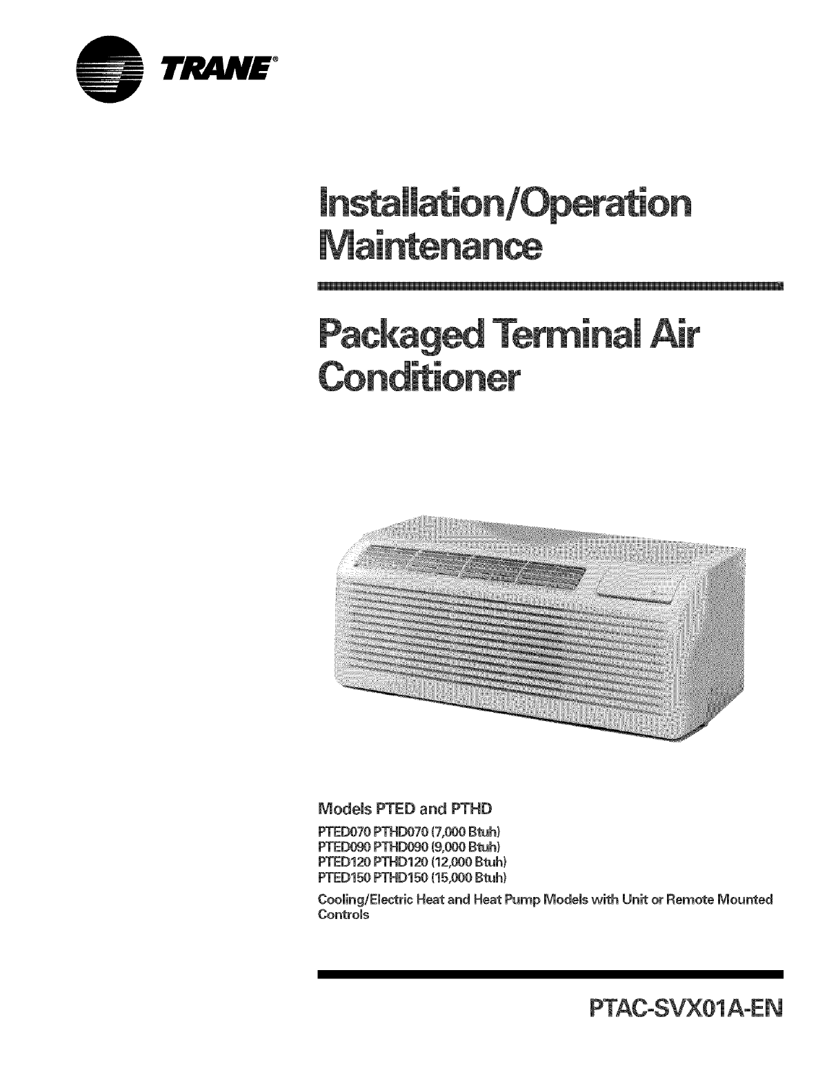
Models PTED and PTHD
PTED070 PTHD070 (7,000 Btuhl
PTED090 PTHD090 (9,000Btuh}
PTED120 PTHD120 (12,000 Btuh)
PTED150 PTHD150 (15,000 Btuh)
Cooling/Electric Heat and Heat Pump Models with Unit or Remote Mounted
Controls
lrR/ij £ °
Warnings and
Warnings and Cautions appear at appropriate sections throughout this manual
Read these carefully.
A_. WARN|NG -indicates a potentially hazardous situation which, if not avoided, could result in
death or serious injury.
,_. CAUT|ON -indicates a potentially hazardous situation which, if not avoided, may result in
minor or moderate injury, it may also be used to alert against unsafe practices.
CAUTION -indicates a situation that may result in equipment or property-damage-only accidents.
@ 2002 American Standard Inc. All rights reserved. PTAC SVX01_EN
0 lrJ_ljv£ °
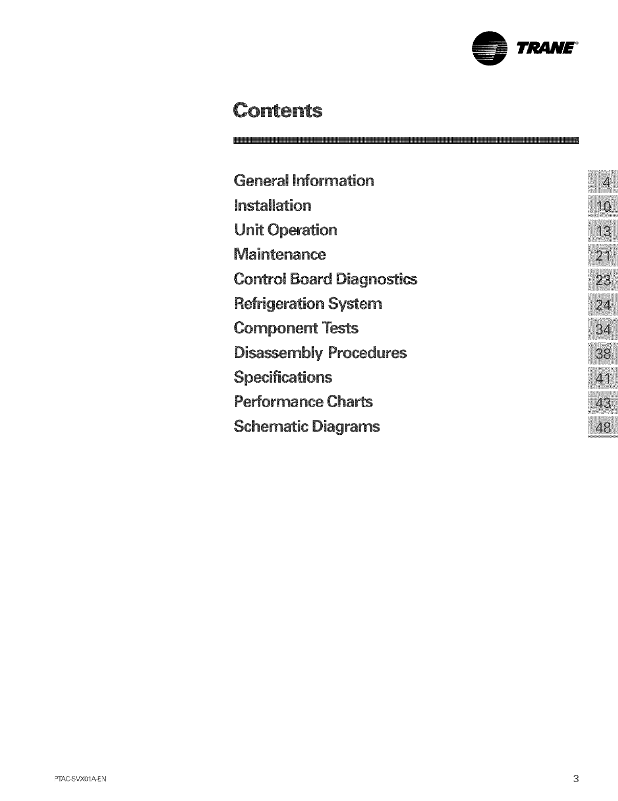
General mnformation
Unit Operation
Control Board Diagnostics
Refrigeration System
Component Tests
Disassembly Procedures
Schematic Diagrams
PTACSVX01 _EN 3
lrJltlN£ °
"I
Transportation Damage
All units are securely packed in Trane
approved shipping containers. The
carton should be checked upon
ardval for external damage, if
damage is found, a wrkten request
for inspection by the carrier's agent
should be made immediately,
in the event of damage, the
consignee should:
1. Make notation on delivery receipt
of any visible damage to shipment
or container.
2. Notify carrier promptly and request
an inspection.
3. in case of concealed damage,
carrier should be notified as soon
as possible, prderably within five
(5) days.
4. Fib the claim with the following
supporting documents vvkMn the
six (6) month statute of limitations.
a. Odginal Bill of Lading, certified
copy, or indemnity bond.
b. Original paid freight bill or
indemnity in lieu thereof.
c. Original invoice or certified
copy thereof, showing trade
and other discounts or
reductions.
d. Copy of the inspection report
issued by carrier's
representative at the time
damage is reported to the
carrier.
The carrier is responsible for making
prompt inspection of damage and for
a thorough investigation of each
claim. The distributor or
manufacturer w,ill not accept claims
from dealers for transportation
damage.
Unit Accessories
This unit is designed for through-the-
wall installation in new or existing
buildings. To complete the
installation of this PTAC, an insulated
wall sleeve and an outdoor grille
(either the stamped aluminum grille
or the architectural grille) are
required.
The chassis and the cabinet front are
shipped in one carton. Optional
items to complete a particular
installation can be found in the PTAC
product catalog.
Literature Change History
PTEC-M-1 (September 1997}
Original issue of manual; specifically
intended for use by experienced
service technicians. Provides
operation and maintenance
procedures for PTECand PTHC units
of "C" and later designs. Unit
specifications, performance data and
typical wiring diagram(s) are also
included. (RS4200002 397)
PTAC-SVN02A-EN (July 2002)
Product update. New control board
features.
PTAC-SVX01A-EN (September 2002)
Combined PTAC-SVN01A-EN and
PTAC-SVU01A-EN.
4_FAC svx01 _EN
°
EnvironmentaU Accountability
Pomicy
Trane urges that all HVAC servicers
working on Company equipment or
any manufacturer's products, make
every effort to eliminate, if possible,
or vigorously reduce the emission of
CFC,HCFCand HFC refngerantsto
the atmosphere resulting from
installation, operation, routine
maintenance, or major service on
this equipment. Always act in a
responsible manner to conserve
refrigerants for continued usage even
when acceptable alternatives are
available.
Recover and Recycle Refrigerants
Refrigerant used in centnfugal water
cNllers should be recovered and/or
recycled for reuse, reprocessed
(reclaimed), or properly disposed of,
whenever it is removed from the
equipment. Never release to
atmosphere! Always determine
recycle or reclaim requirements of
the refrigerant before beginning
recovery procedure. Obtain a
chemical analysis of the refrigerant if
necessary. (Questions about
recovered refrigerant and acceptable
refrigerant quality standards are
addressed in ARI Standard 700).
Refrigerant Handling and Safety
Consult manufacturer's Matedal
Safety Data Sheets (MSDS) on
refrigerants being handled to
understand health, safety, storage,
handling and disposal requirements.
Use approved containment vessels
and refer to appropriate safety
standards. Comply with all
applicable transportation standards
when shipping refrigerant containers.
Service Equipment and Procedures
To minimize refrigerant emissions
while recovering the refrigerant, use
recycling equipment such as a
Company recycle/recovery system or
equivalent. Use equipment and
methods which will pull the lowest
possible system vacuum while
recovering and condensing
refrigerant. Equipment capable of
pulling a vacuum of less than 1,000
microns (1.0 ram) of mercury is
recommended. Do not open the unit
to atmosphere for service work until
the refrigerant charge is fully
removed/recovered. When leak=
testing with trace refrigerant and
nitrogen, use HCFC=22(R=22)rather
than CFCq2 (R-12) or any other fully
halogenated refrigerant. Be aware of
any new leak test methods which
may eliminate refrigerants as a trace
gas. Evacuation prior to charging
should be done with a vacuum pump
capable of pulling a vacuum of 1,000
microns (1.0 mm) of mercury or less.
The unit should stand for 12 hours
and the vacuum should not rise
above 2,500 microns (2.6 mm) of
mercury. A rise above 2,500 microns
(2.5 mm) of mercury indicates a leak
test is required to locate and repair
any leaks. A leak test wiii be required
on any repaired area. Charge
refrigerant into the machine only
when it is determined that the
machine does not leak or contain
moisture. Charge refrigerant into the
machine by weight. A proper charge
is required for efficient machine
operation. When charging is
complete, purge or drain charging
lines into an approved refrigerant
container. Seal all used refrigerant
containers with approved closure
devices to prevent unused refrigerant
from escaping to the atmosphere.
Take extra care to properly maintain
all service equipment directly
supporting refrigerant service work
such as gauges, hoses, vacuum
pumps, and recycling equipment.
When cleaning system components
or parts, avoid using CFC-11 (R-11) or
CFC-113 (R-113). Use only cleaning-
solvents that do not have ozone
depletion factors. Properly dispose of
used materials. Refrigeration system
cleanup methods using filters and
driers are preferred. Maintain the
purge unit on centrifugal water
chillers in proper working condition.
An improperly maintained purge unit
can cause significant refrigerant
emissions to the atmosphere.
Consider replacing older operational
purge units with the new Company
Purifier Purge unit. Excessive purge
operation is an indication of possible
refrigerant leakage. Check for leaks
when excessive purge operation is
observed.
Keep abreast of unit enhancements,
conversion refrigerants, compatible
parts, and manufacturer's
recommendations which will reduce
refrigerant emissions and increase
equipment operating efficiencies.
Follow specific manufacturer's
guidelines for conversion of existing
equipment. Use only Company
approved gaskets, O-rings, oil filters,
and other components on centrifugal
water chillers or CenTraVacs. in order
to assist in reducing power
generation requirements, always
attempt to improve chiller equipment
performance with improved
maintenance operations which will
help conserve energy resources.
items to be considered include tube
cleanliness, proper water flows,
correct refrigerant charge, cooling
tower maintenance, and proper
operation of controls and features
such as free cooling, chilled water
reset functions, and time of day
scheduling.
PTAC SVX01AEN 5
lrJ .N£ °
"I
Pride and workmanship go into
every product to provide our
customers with quality products, it is
possible, however, that during its
lifetime a product may require
service. Products should be serviced
only by a qualified service technician
who is familiar with the safety
procedures required in the repair
and who is equipped vvkh the proper
tools, parts, testing instruments and
the appropriate service manual.
Live Electrical Components!
installation, testing, servicing
and troubleshooting of this product,
it mav be necessary to work with
live electrical components. Have a
qualified licensed electrician or other
individual who has properly trained
in live eJe_ricai components
perform these tasks. Failure to
precautions when exposed to live
electrical components could result in
death or serious injury.
6 PFAC SVX01_EN
lrJ!iliN£ °
Unit Features
The Trane PTAC has many features,
some of vvhbh are different than
those found on convendonaU PTAC
units. The servicer must be famiUiar
with these features in order to
propedy service the unit.
, Automatic 3-minute Compressor
Lockout - After the compressor
cycbs off, it wHUnot restart for three
minutes. This feature prevents the
compressor from short cycling and
extends the overall Uife.
° Automatic 2rid Stage Electric Heat
(PTHD only} - if the room
temperature falls to 2.5° F beUow
the setpoint temperature or the unit
compressor falls, the reverse cycle
heat is shut off and the ebctdc heat
is turned on.
,indoor Room Freeze Protection -
When the unit senses room
temperatures of 40°F or beUow,the
unit activates the fan motor and
either the eUectricresistance heater
or the hydronic heater to help
prevent pipes or fixtures from
freezing. This also overrides front
desk control of the unit mounted or
wall mounted controls.
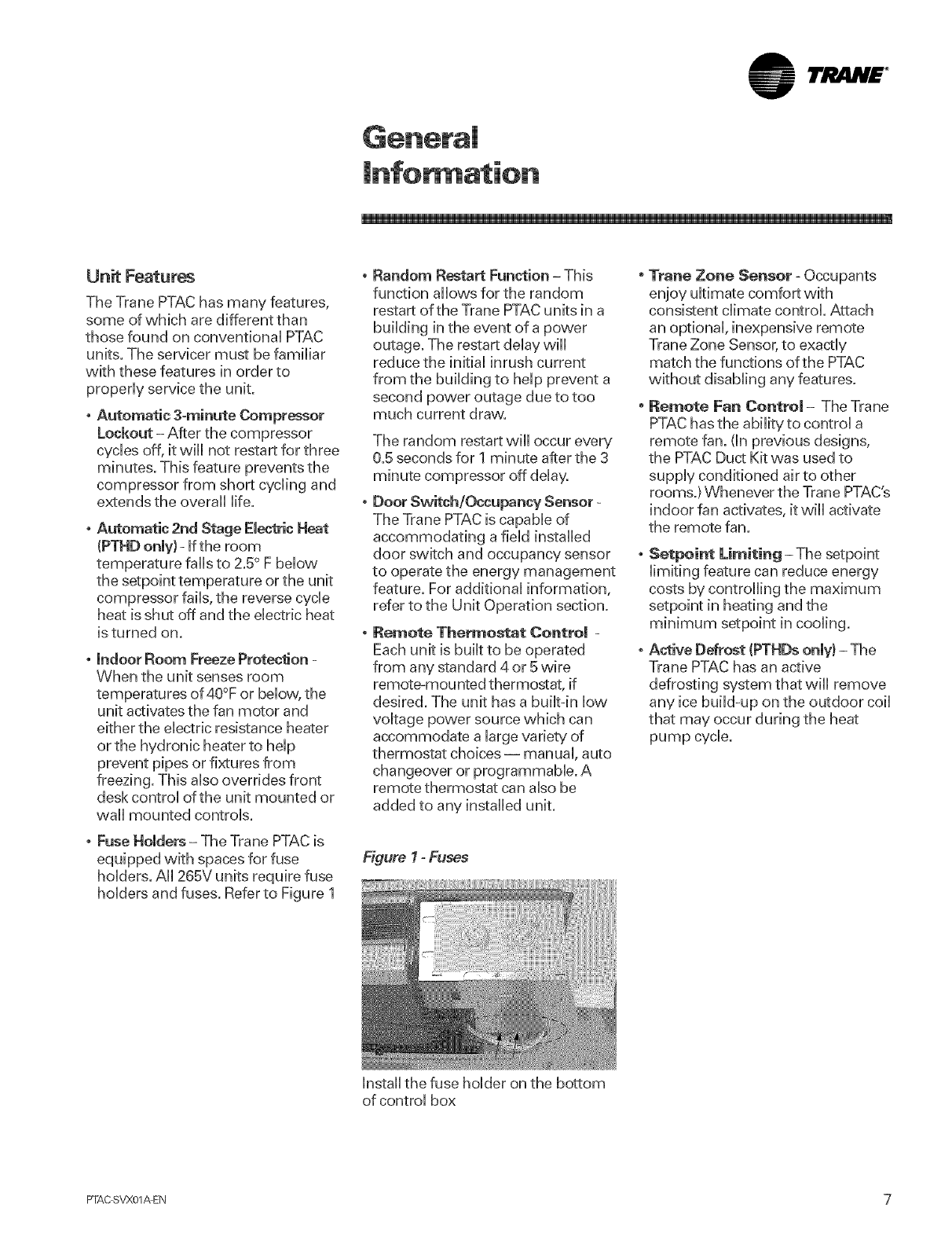
.Fuse Holders - The Trane PTAC is
equipped with spaces for fuse
holders. All 265V units require fuse
holders and fuses. Refer to Figure 1
Random Restart Function -This
function allows for the random
restart of the Trane PTAC units in a
building in the event of a power
outage. The restart delay will
reduce the initial inrush current
from the building to help prevent a
second power outage due to too
much current draw.
The random restart will occur every
0.5 seconds for 1 minute after the 3
minute compressor off delay.
, Door Switch/Occupancy Sensor -
The Trane PTAC is capable of
accommodating a field installed
door switch and occupancy sensor
to operate the energy management
feature. For additional information,
refer to the Unit Operation section.
oRemote Thermostat Contro| =
Each unit is built to be operated
from any standard 4 or 5 wire
remote-mounted thermostat, if
desired. The unit has a buik-in low
voltage power source which can
accommodate a large variety of
thermostat choices- manual, auto
changeover or programmable. A
remote thermostat can also be
added to any installed unit.
Figure l-Fuses
Install the fuse holder on the bottom
of control box
"Trane Zone Sensor - Occupants
enjoy ultimate comfort with
consistent climate control. Attach
an optional, inexpensive remote
Trane Zone Sensor, to exactly
match the functions of the PTAC
without disabling any features.
, Remote Fan Centre| - The Trane
PTAC has the ability to control a
remote fan. (in previous designs,
the PTAC Duct Kit was used to
supply conditioned air to other
rooms.} Whenever the Trane PTAC's
indoor fan activates, it will activate
the remote fan.
Serif:tint Limiting = The setpoint
limiting feature can reduce energy
costs by controlling the maximum
minimum setpoint in cooling.
Active Defrost (PTHDs only) - The
Trane PTAC has an active
defrosting system that will remove
any ice build-up on the outdoor coil
that may occur during the heat
pump cycle.
PTAC SVX01AEN 7

lrj .N£ °
Unit Accessories
Modei Number
AAGSP
AAGAL
AAGDB
AAGSD
AUXWHRE
SAG01
SAG10
CB0115
CB0120
CB0130
CB0415
CDP01
CDP02
DRAIN
HLTR10
FUSE0115
FUSE0120
FUSE0130
HSK01
HSK02
Description
Architectural Aluminum Grilles- Special Color
Architectural Aluminum Grille-Anodized finish
Architectural Aluminum Grille - Dark Bronze
Architectural Aluminum Grille -Soft Dove
Wire Harness Kit
Stamped Aluminum Grilles -Sinqle Pack
Stamped Aluminum Grilles - Ten Pack
Circuit Breaker 230V, 15A
Circuit Breaker 230V, 20A
Circuit Breaker 230V, 30A
Circuit Breaker 115V, 15A
Condensate Pump 230/208V
Condensate Pump 265V
Drain Kit
Ten Pack Filter Kit
Fuse Holder Kit 230/208V, 15A
Fuse Holder Kit 230/208V, 20A
Fuse Holder Kit 230/208V, 30A
Hydronic Steam Heat Kit - 230/208V
Hydronic Steam Heat Kit - 265V
Model Number
HSK04
HWIREK
HWK04
HWK02
HWK01
LVLG02
PS0130
KEYLOK
PS0230
REK10
SUB0120
SUB0130
SUB0220
SUB0230
TAYSTAT340
TAYSTAT371
TAYSTAT540
TAYSTAT570
WS130
WS180
WS240
PFC01
ZONSENS
Description
Hydronic Steam Heat Kit -115V
Hard Wire Kit
Hydronic Water Heat Kit - 115V
Hydronic Water Heat Kit - 265V
Hydronic Water Heat Kit - 230/208V
Wall Sleeve Levelling Legs
Power Switch 230/208V, 30 A
Control Panel Key Lock
Power Switch 265V, 30 A
Remote Escutcheon Kits- 10 Pack
Subbase 230/208V, 20A
Subbase 230/208V_ 30A
Subbase 265V, 20A
Subbase 265V; 30A
1H/lC Di_q Tstat (4-wire Pwr Steal)
1H/1C Digital NonProg Tstat
(4-wire Pvvr Steal)
2H/1C Heat Pump Digital Prog Tstat
2H/1C Heat Pump Digital NonProq Tstat
Standard Wall Sleeve
Extended 18" Wall Sleeve
Extended 24" Wall Sleeve
Plastic Front Cover
Zone Sensor
8 PFAC SVX01_EN
lrli4H£ °
Mode! Number Description
For service purposes, ModeU PTED,
PTHD Package Terminal Air
Conditioner/Heat Pumps are
assigned a muUdpb-character
aUphanumerb modeUnumber that
preciseUyidentifies each unit. An
expUanadon of the identification code
that appears on the unit namephte is
shown bebw.
Use of the service model number will
enable the owner/operator, installing
contractors, and service technicians
to define the operation, components
and options for any specific unit.
Refer to the model number printed
on the panel nameplate when
ordering replacement parts or
requesting service.
PT E D 090 1 6 e A
12 3 4 567 8 9 10 11
Digits !,2 --Packaged Terminal
Air Conditioner
Digit 3- Product Type
E = Air Conditioner
H = Heat Purr@
Digit 4-- Development Sequence
D = Fourth Development
Digits 5,6, 7- Unit Cooling
Capacity
070 = 7,000 Btu
090 = 9,000 Btu
120= 12,000Btu
150= 15,000Btu
Digit 8-- Main Power Supply
1 = 208-230V/60Hz/1phase
2 = 265V/60Hz/1phase
4 = 115V/60Hz/lphase*
Digit 9-- Electric Heating Capacity *_
w= Hydronic_
D = 2.0 kW
G = 3.5 kW - 208-230V
G = 3.7 kW - 265V
J = 5 kW_÷_
Digit 10 -- Des@n Sequence
D_Tit 1!-- Miscellaneous
A = Standard
C = Corrosion Resistant
D = Condensate Pump
*Hydronic unit only. Sizes 07, 09, and !2 only,
**All heat pump units must have electric coils
__Hydronic units ship with no electric heat and no plastic front cover The hydronic kit, which must be ordered
separately, includes a metal front cover.
Sizes 09 12 and 15 only.
PTAC SVX01AEN 9
lrJltlN£ °
Attention mnstaHation
Personnel
As a professional installer you have
an obligation to knovvthe product
better than the customer. This
includes all safety precautions and
related items.
Prior to actual installation,
thoroughly familiarize yourself with
this instruction Manual. Pay special
attention to ai[ safety warnings. Often
during installation or repair it is
possible to place yourself in a
position which is more hazardous
than when the unit is in operation.
Remember, it is your responsibility to
install the product safely and to know
it weil enough to be able to instruct a
customer in its safe use.
Safety is a matter of common
sense--a matter of thinking before
acting. Most dealers have a list of
specific good safety practices--
follow them.
About This ManuaU
important Note: To prevent machine
damage, contact aquMified service
organization to perform the check-out
procedure described at the end ofthis
manual r.
important Note to the Owner
This equipment is to be serviced by
professionally trained personnel
only. Ifthis equipment is improperly
installed, adjusted or altered by an
unqualified person, a safety hazard
may result.
mmportant Note to the Servicer
Read this manual and familiarize
yourself with the specific items
which must be adhered to before
attempting to service this unit. The
precautions listed in this manual
should not supersede existing
practices but should be considered
as supplemental information.
General
To ensure that the unit operates
safely and efficiently, it must be
installed, operated and maintained
according to these installation and
operating instructions and all local
codes and ordinances or, in their
absence, with the National Electric
Code. The proper installation of this
unit is described in the following
sections. Following the steps in the
order presented should ensure
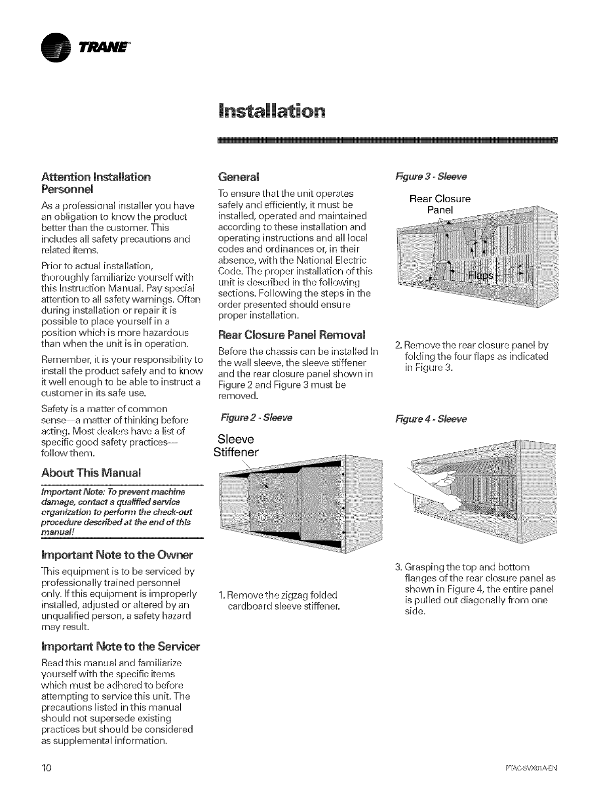
Rear CmosurePanel Removal
Before the chassis can be installed In
the wall sleeve, the sleeve stiffener
and the rear closure panel shown in
Figure 2 and Figure 3 must be
removed.
Figure 2 - Sleeve
Sleeve
Stiffener
\
1. Remove the zigzag folded
cardboard sleeve stiffener.
Figure 3 - Sleeve
Rear Closure
Panel
2. Remove the rear closure panel by
folding the four flaps as indicated
in Figure 3.
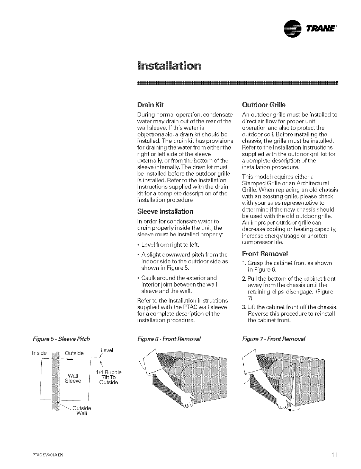
Figure 4 - Sleeve
3. Grasping the top and bottom
flanges of the rear closure panel as
shown in Figure 4, the entire panel
is pulled out diagonally from one
side.
10 PI-AC SVX01AEN
1rRAN£ °
Drain Kit
During normal operation, condensate
water may drain out of the rear of the
wall sleeve. IftNs water is
objectionable, a drain kit should be
installed. The drain kit has provisions
for draining the water from either the
right or left side of the sleeve
externally, or from the bottom of the
sleeve internally. The drain kit must
be installed before the outdoor gdlle
is installed. Refer to the Installation
instructions supplied with the drain
kit for a complete description of the
installation procedure
Sleeve mnstallation
in order for condensate water to
drain properly inside the unit, the
sleeve must be installed properly:
o Level from right to left.
o A slight downward pitch from the
indoor side to the outdoor side as
shown in Figure 5.
o Caulk around the exterior and
interior joint between the wall
sleeve and the wall.
Refer to the Installation instructions
supplied with the PTACwall sleeve
for a complete description of the
installation procedure.
Outdoor Grille
An outdoor grille must be installed to
direct air flow for proper unit
operation and also to protecstthe
outdoor coil. Before installing the
chassis, the grille must be installed.
Refer to the Installation instructions
supplied with the outdoor grill kit for
a complete description of the
installation procedure.
This model requires either a
Stamped Grille or an Architectural
Grille. When replacing an old chassis
with an existing grille, please check
with your sales representative to
determine if the new chassis should
be used with the old outdoor grille.
An improper outdoor grille can
decrease cooling or heating capacity,
increase energy usage or shorten
compressor life.
Front Removal
1. Grasp the cabinet front as shown
in Figure 6.
2. Pull the bottom of the cabinet front
away from the chassis until the
retaining clips disengage. (Figure
7_
3. Lift the cabinet front off the chassis.
Reverse this procedure to reinstall
the cabinet front.
Figure 5- Sleeve Pitch
mosideii Wall
Sleeve
_ Outside
Wall
Level
_/
\
1/4 Bubble
Tilt To
Outside
Figure 6- Front Removal Figure 7- Front Removal
PTAC SVX01_EN 1 1
lrJltlN£ °
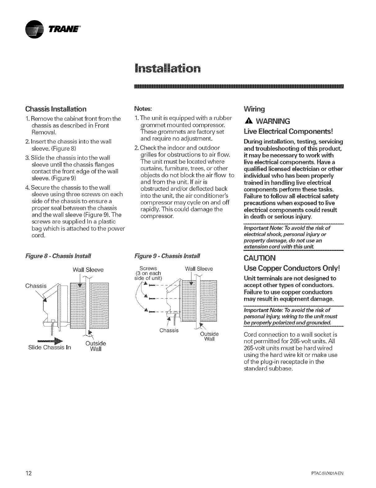
Chassis installation
1. Remove the cabinet front from the
chassis as described in Front
Removal
2. insert the chassis into the wall
sleeve. (Figure 8)
3. Slide the chassis into the wall
sleeve until the chassis flanges
contact the front edge of the wall
sleeve. (Figure 9)
4. Secure the chassis to the wall
sleeve using three screws on each
side of the chassis to ensure a
proper seal between the chassis
and the wall sleeve (Figure 9). The
screws are supplbd in a plastb
bag wNch is attached to the power
cord.
Figure 8 - Chassis Install
Chassis
Wall Sleeve
/
?.o
Slide Chassis mn Outside
Wall
Notes:
1.The unit is equipped wkh a rubber
grommet mounted compressor.
These grommets are factory set
and require no adjustment.
2. Checkthe indoor and outdoor
grilles for obstructions to air flow.
The unit must be located where
curtains, furniture, trees, or other
objects do not block the air flow to
and from the unit. If air is
obstructed and/or deflected back
into the unit, the air conditioner's
compressor may cycle on and off
rapidly. This could damage the
compressor.
Figure 9 - Chassis Install
Screws WaimShove
Chassis Outside
Waim
Wiring
_k WARNING
Live ElectdcaU Components!
During installation, testing, servicing
and troubleshooting of this product,
it may be necessary to work with
mireemectricamcomponents, Have a
qualified licensed electrician or other
individual who has been properly
trained in handling live elestricai
components perform these tasks.
Failure to follow all electrical safety
precautions when exposed to live
electrical components could result
in death or serious injury.
Important Note: To avoid the risk of
e/ectdcM shock, personM injury or
property damage, do net use an
extension cord with this unit.
Use Copper Conductors Only!
Unit terminals are not designed to
accept other types of conductors.
Failure to use copper conductors
may result in equipment damage.
important Note: To avoid the risk of
persona! injury, wiring to the unit must
be properly pMarized and grounded.
Cord connection to a wall socket is
not permitted for 265-volt units. All
265-volt units must be hard wired
using the hard wire kit or make use
of the plug-in receptacle in the
standard subbase.
12 FFAC SVX01AEN
lri!i4H£ °
Unit Operation
Operating instructions
Users Controls
Two rotary knobs controlling
temperature and operational mode
are located behind the controU door
Uocatedto the top-right of the cabinet
front.
Temperature Control SetlJng
Turning the temperature controU
clockw,ise w,ill provide a warmer
room temperature; turning it
counterclockwise will provide a
cooler room temperature. Adjusting
the temperature control to the mid
setting (vertical)will set the room
temperature at approximateUy 70° R
A Hazardous Voltage!
Disconnect all electric power,
including remote disconnects before
servicing. Follow proper lockout/
tagout procedures to ensure the
power can not be inadvertently
energized. Failure to disconnect
power before servicing could result
in death or serious injuW.
Mode Switch
The table below describes the unit
function corresponding to the
various mode switch settings.
HIGH HEAT Heat pump operation/Electric Heat will
operate along with the high fan setting.
LOW HEAT Heat pump operation/Electric Heat will
operate along with the low fan setting.
HIGH FAN The unit will operate in the high fan mode only.
LOW FAN The unit will operate in the low fan mode only.
OFF Fan based on settings of dip
switches #1 and #2; No Heat, No Cool.
The unit will operate in the cooling
mode along with the low fan operation.
LOW COOL
The unit will operate in the cooling
HIGH COOL mode along with the high fan operation.
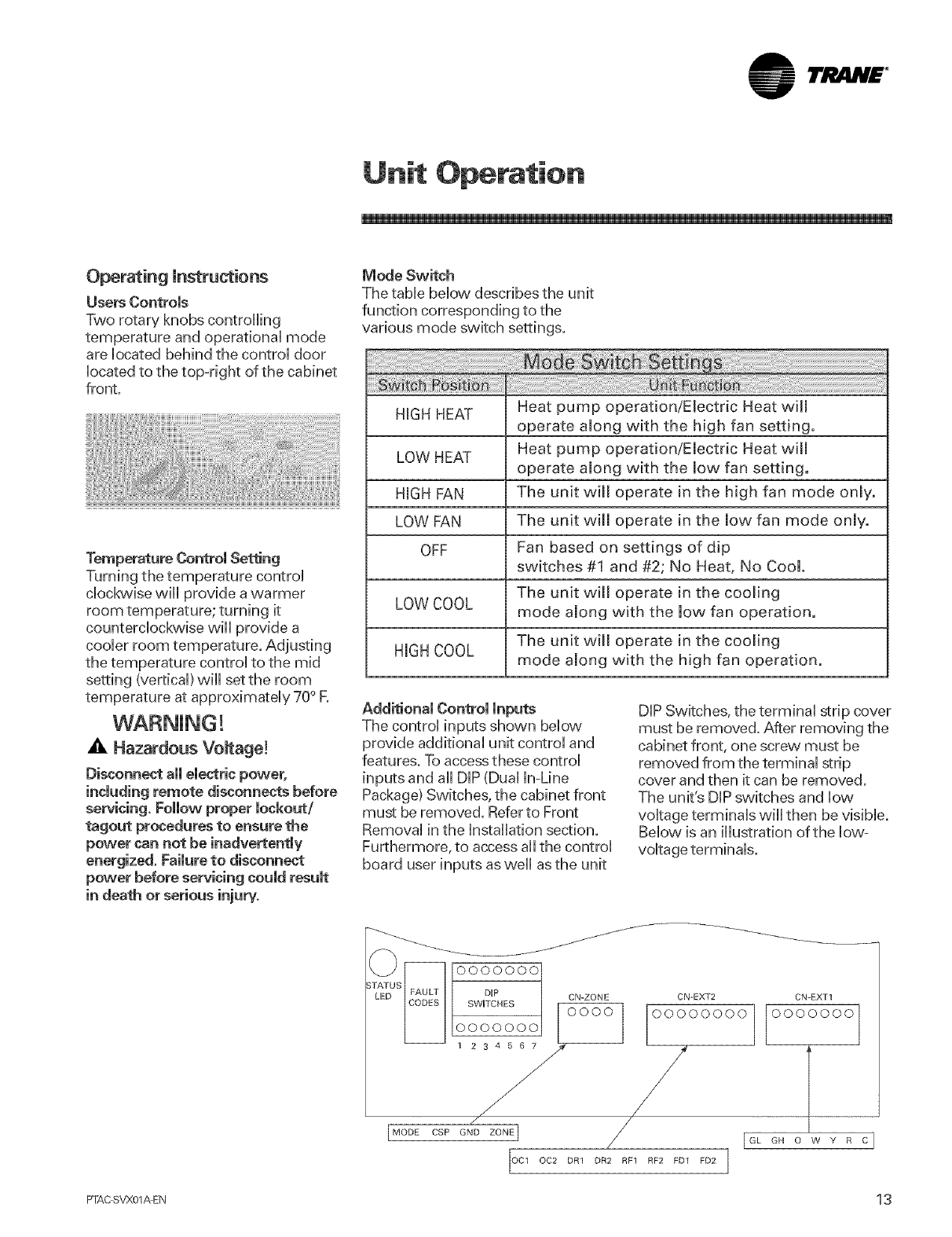
Additional Control inputs
The control inputs shown below
provide additional unit control and
features. To access these control
inputs and all DIP (Dual In-Line
Package) Switches, the cabinet front
must be removed. Referto Front
Removal in the Installation section.
Furthermore, to access all the control
board user inputs as well asthe unit
DIP Switches, the terminal strip cover
must be removed. After removing the
cabinet front, one screw must be
removed from the terminal strip
cover and then it can be removed.
The unit's DIPswitches and low
voltage terminals will then be visible.
Below, is an illustration of the low=
voltage terminals.
S_S FAULq_ 10000000
sw, Esc zoN [ooooooo
PTAC SVX01AEN 1 3
I'JltlN£ °
Unit Operation
A WARNING!
Hazardous Vomtage!
Disconnect all electric power,
including remote disconnects before
servicing. Follow proper lockout/
tagout procedures to ensure the
power can not be inadvertently
energized. Failure to disconnect
power before servicing could result
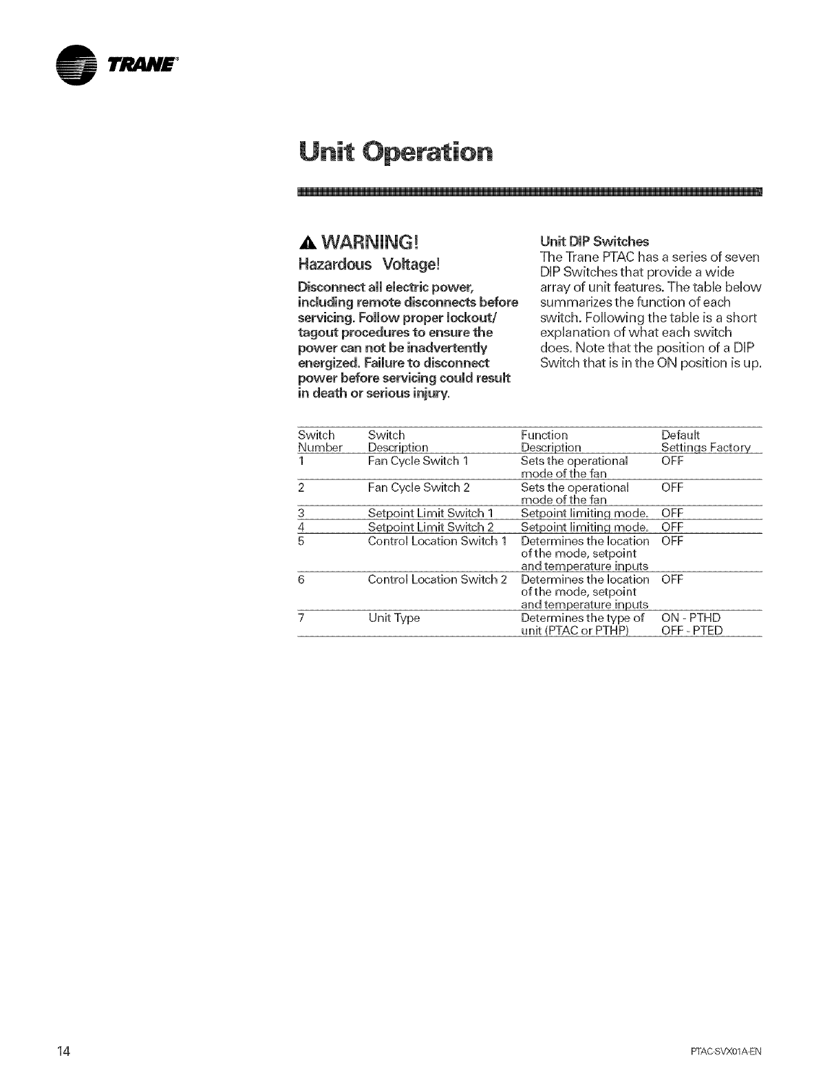
Unit DiP Switches
The Trane PTAChas a series of seven
DUPSwitches that provide a wide
array of unit features. The tame below
summarizes the function of each
switch. Following the tame is a short
expUanation of what each switch
does. Note that the position of a DUP
Switch that is in the ON position is up.
Switch Switch
Number Description
1 Fan Cycle Switch 1
3
4
5
Fan Cycle Switch 2
Setpoint Limit Switch 1
Setpoint Limit Switch 2
Control Location Switch 1
Control Location Switch 2
Unit Type
Function Default
Description Settin.qs Factory
Sets the operational OFF
mode of the fan
Sets the operational OFF
mode of the fan
Setpoint limitinq mode. OFF
Setpoint limitinq mode, OFF
Determines the location OFF
of the mode, setpoint
and temperature inputs
Determines the location OFF
of the mode, setpoint
and temperature inputs
Determines the type of ON - PTHD
unit (PTAC or PTHP} OFF - PTED
14 PFAC SVX01_EN
lri!i4H£ °
Unit Operation
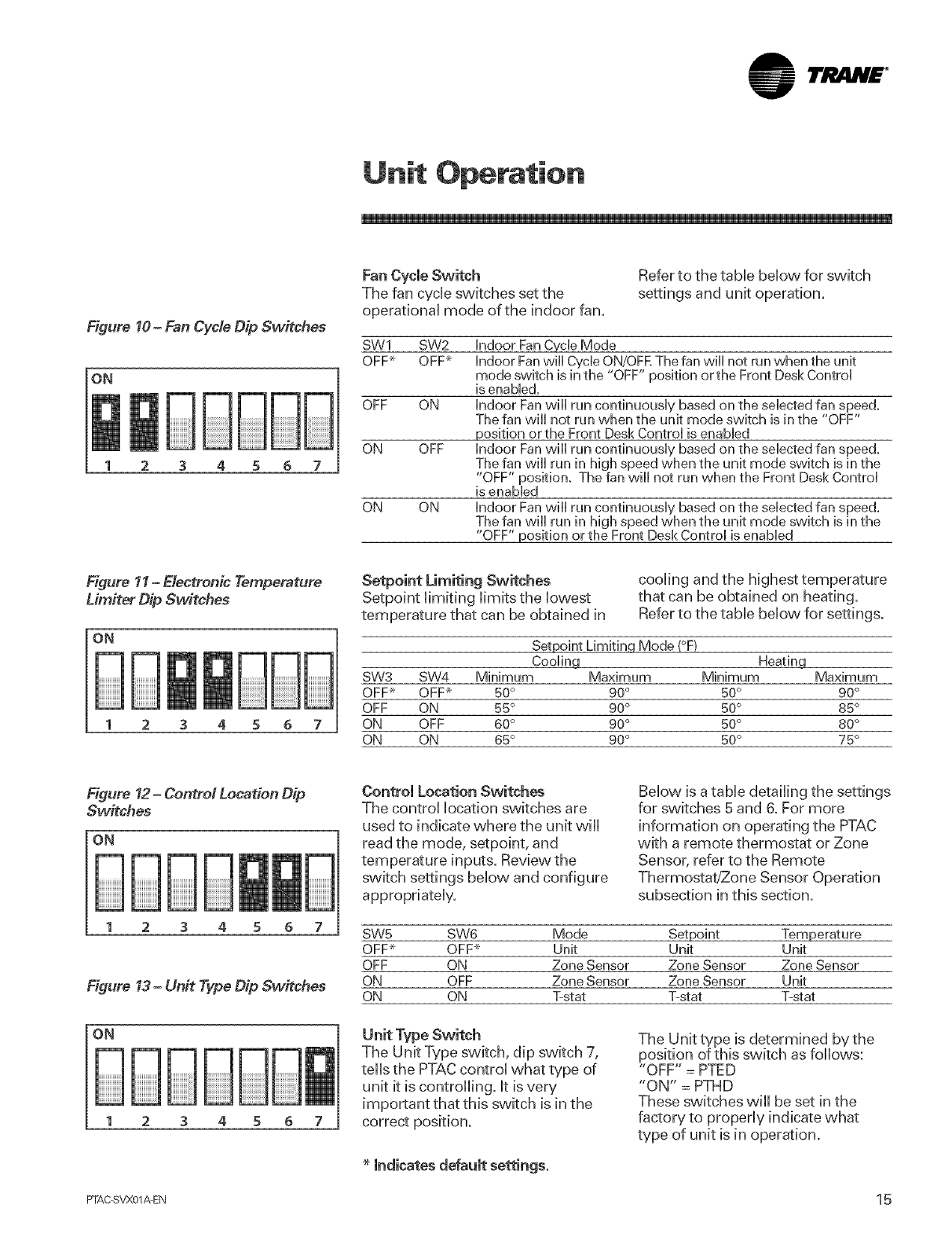
Figure 10-Fan Cycle Dip Switches
ON
3 4 5 6 7
Fan Cycle Switch
The fan cycb switches set the
operational mode of the indoor fan.
Refer to the tame below for switch
settings and unit operation.
SW1
OFF-_
OFF
ON
ON ON
SW2 indoor Fan Cycle Mode
OFF_ Indoor Fanwill Cycle ON/OFE The fan will not run when the unit
mode switch is in the "OFF" position orthe Front Desk Control
is enabled.
ON indoor Fan will run continuously based on the selected fan speed.
The fan will not run when the unit mode switch is in the "OFF"
position or the Front Desk Control is enabled
OFF indoor Fan will run continuously based on the selected fan speed.
The fan will run in high speed when the unit mode switch is in the
"OFF" position. The fan will not run when the Front Desk Control
is enabled
indoor Fan will run continuously based on the selected fan speed,
The fan will run in high speed when the unit mode switch is in the
"OFF" position orthe Front Desk Control is enabled
Figure 11-Electronic Temperature
Lim#er Dip Switches
5 5
Setpoint Limiting Switches
Setpoint limiting limits the lowest
temperature that can be obtained in
cooling and the highest temperature
that can be obtained on heating,
Refer to the table below for settings.
Setpoint Limiting Mode (°F}
Coolinq Heatinq
SW3 SW4 Minimum Maximum Minimum Maximum
OFF_ OFF_ 50° 90° 50° 90°
OFF ON 55° 90° 50° 85°
ON OFF 60° 90° 50° 80°
ON ON 65° 90° 50° 75°
Figure 12 -Control Location Dip
Sw#ches
5 6
Figure 13-Unit Type Dip Switches
Control Location Switches
The control location switches are
used to indicate where the unit will
read the mode, setpoint, and
temperature inputs. Review the
switch settings below and configure
appropriately.
Below is a table detailing the settings
for switches 5 and 6. For more
information on operating the PTAC
with a remote thermostat or Zone
Sensor, refer to the Remote
Thermostat/Zone Sensor Operation
subsection in this section.
SW5 SW6 Mode Setpoint Temperature
OFP OFP Unit Unit Unit
OFF ON Zone Sensor Zone Sensor Zone Sensor
ON OFF Zone Sensor Zone Sensor Unit
ON ON T=stat T-stat T-stat
The Unit Type switch, dip switch 7,
tells the PTAC control what type of
unit it is controlling, it is very
important that this switch is in the
correct position.
indicates default settings.
The Unit type is determined by the
position of this switch as follows:
"OFF" = PTED
"ON" = PTHD
These switches will be set in the
factory to properly indicate what
type of unit is in operation.
PTAC SVX01AEN 1 5
TJ .N£ °
Unit Operation
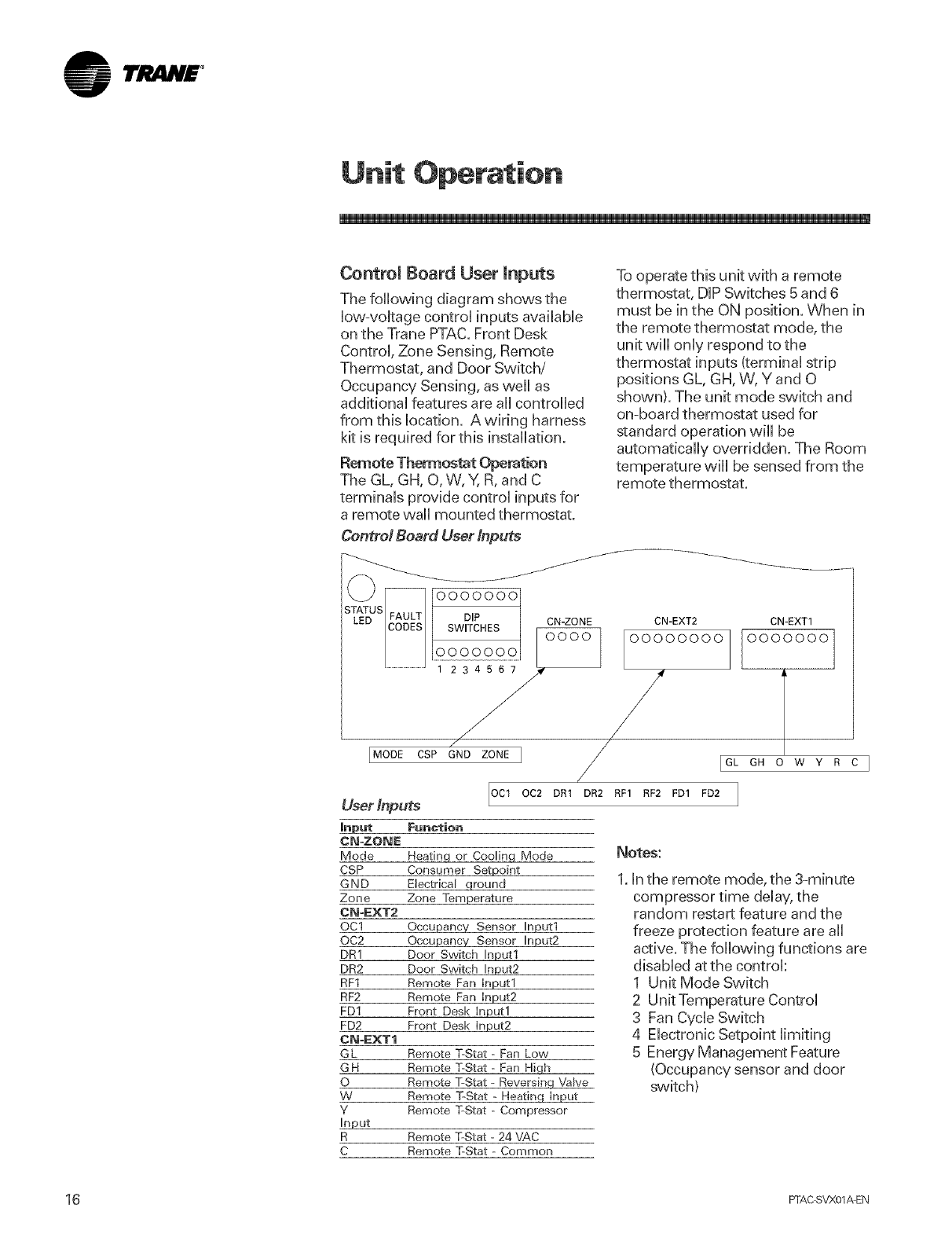
Control Board User Inputs
The foflowing diagram shows the
[ovv-voUtagecontro[ inputs avaiUaMe
on the Trane PTAC. Front Desk
Contro[, Zone Sensing, Remote
Thermostat, and Door Switch/
Occupancy Sensing, as we[[ as
additiona[ features are aH controlled
from this [ocation. A wiring harness
kit is required for this installation.
Remote Thermostat Operation
The GL, GH, O, W, Y, R, and C
terminaUs provide control inputs for
a remote wall mounted thermostat.
Control Board User Inputs
oooooo_o j_
SWITCHES CN-ZONE
..... 23456/_ /
IMODEcsP GNDZO.EI
User Inputs
Input
CN-ZO@E
Mode
CSP
GND
Zone
CN-r:XT2
©C1
OC2
DR1
DR2
RF1
RF2
FD1
FD2
CN-_:XT1
GL
GH
O
W
Y
Input
R
C
OC1 OC2 DR1
Function
Heatinq or Cooling Mode
Consumer Setpoint
Electrical ground
Zone Temperature
Occupancy Sensor Input1
Occupancy Sensor Input2
Door Switch Input1
Door Switch Input2
Remote Fan Input1
Remote Fan Input2
Front Desk Input1
Front Desk Input2
Remote T-Stat - Fan Low
Remote %Stat - Fan High
Remote %Stat - Reversing Valve
Remote %Stat - Heating Input
Remote T-Stat - Compressor
Remote %Stat - 24 VAC
Remote T-Stat - Common
To operate this unit with a remote
thermostat, DIP Switches 5 and 6
must be in the ON position. When in
the remote thermostat mode, the
unit will only respond to the
thermostat inputs (terminal strip
positions GL, GH, W, Y and O
shown). The unit mode switch and
on-board thermostat used for
standard operation will be
automatically overridden. The Room
temperature will be sensed from the
remote thermostat.
CN-EXT2 CN-EXT1
OOOOOO00 OOOOOOO
/
DR2 RF1 RF2 FD1 FD2
GH O W Y R C I
Notes:
1. In the remote mode, the 3-minute
compressor time delay, the
random restart feature and the
freeze protection feature are all
active. The following functions are
disabled at the control:
1 Unit Mode Switch
2 Unit Temperature Control
3 Fan Cycle Switch
4 Electronic Setpoint limiting
5 Energy Management Feature
(Occupancy sensor and door
switch)
16 FFAC SVX01_EN
TI!iliN£ °
Unit Operation
A, WARNING!
Hazardous Vomtage!
Disconnect aimele_ric power,
including remote disconne_s before
servicing. Fefiow proper lockout/
tagout procedures to ensure the
power can not be inadvertently
energized. Failure to disconnect
power before servicing could result
in death or serious injury.
A, WARNING!
Hazardous Vomtage!
Disconnect aimele_ric power,
including remote disconne_s before
servicing. Fefiow proper lockout/
tagout procedures to ensure the
power can not be inadvertently
energized. Failure to disconnect
power before servicing could result
Remote Thermostat Location
This unit is designed to be operated
with any4 or 5wire remote wall
mounted Thermostats. For further
information on thermostats approved
for use with this unit, contact your
sales representative. For best
performance results, the thermos'tat
should be located approximately five
feet above the floor on a vibration
free inside wall, in an area with good
air circulation. Do not install the
thermostat where it may be affected
bythe following: dead spots behind
doors, in corners or under cabinets,
hot or cold drafts from air ducts,
radiant heat from the sun,
appliances, fireplaces, concealed
pipes, chimneys, unheated
(uncooled) areas behind the
thermostat, such as outside walls.
Consult the instruction sheet
packaged with the thermostat for
further details on mounting and
operation.
Thermostat HEAT/OFF/COOL Switch
OFF - cooling and heating functions
are defeated.
HEAT- the selected room
temperature is maintained by cycling
either in the heat pump mode or
electric heat. A PTHD unit is switched
from the heat pump mode to electric
heat when the outdoor air
temperature is below 20° F
(approximately), or when the heat
pump cannot keep up with the
heating load and a two-stage
thermostat is used.
COOL -the selected room
temperature is maintained by cycling
the air conditioner.
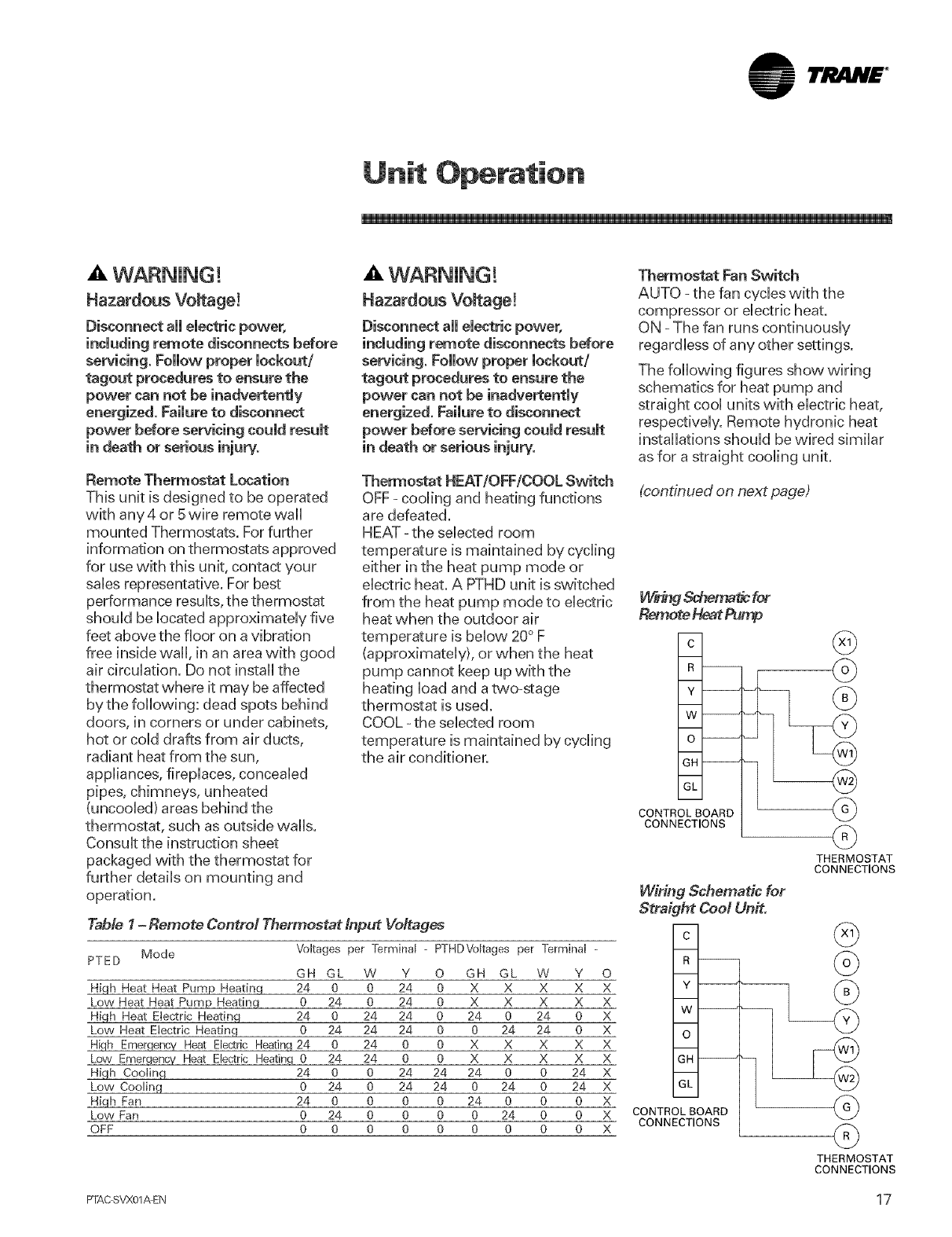
Table 1-Remote Control Thermostat Input Vofages
Mode Voltages per Terminal - PTHDVekages per Terminal -
PTED GH GL W Y O GH GL W Y
High Heat Heat Pump Heating 24 0 0 24 0 X X X X
Low Heat Heat Pump Heating 0 24 0 24 0 X X X X
High Heat Electric Heating 24 0 24 24 0 24 0 24 0
Low Heat Eieetric Heating 0 24 24 24 0 0 24 24 0
High Emergency Heat Electric Heatinq 24 0 24 0 0 X X X X
Lew Emerqenc,/ Heat Electric Heating 0 24 24 0 0 X X X X
High Cooling 24 0 0 24 24 24 0 0 24
Low Cooling 0 24 0 24 24 0 24 0 24
H_qh Fan 24 0 0 0 0 24 0 0 0
Low Fan 0 24 0 0 0 0 24 0 0
OFF 0 0 0 0 0 0 0 0 0
Thermostat Fan Switch
AUTO =the fan cycles with the
compressor or electric heat.
ON - The fan runs continuously
regardless of any other settings.
The following figures show wiring
schematics for heat pump and
straight cool units with electric heat,
respectively. Remote hydronic heat
installations should be wired similar
as for a straight cooling unit.
(continued on next page)
R --
y--
W--
O--
GH--
GL
CONTROL BOARD
CONNECTIONS
14fringSchematic for
Remote Heat Pump
c @
@
@
@
@
THERMOSTAT
CONNECTIONS
R --
O
X Y
XW_
X
X o
X
X GH
X
X GL
X
X CONTROL BOARD
CONNECTIONS
X
Wiring Schematic for
Straight Cool Unit.
c
@
@
THERMOSTAT
CONNECTIONS
PTAC SVX01AEN 17
lrjla.H£ °
Unit Operation
(thermostat section cont.)
NOTE: Ufthethermostat being used
to controUthe Trane PTAC has
connections avaHaMe for GL and GH
(Fan High and Fan Low) the wiring
may be done in that manner. Ufnot,
onUyone orthe other may be used.
Note:
1. For heat pump operation, a room
thermostat with an "0" (heating
changeover) terminaU is required.
This vvHUmean that some "auto
changeover" thermostats cannot
be used, as many of them either
do not have an "0" terminaU, or
eUseenergize the" 0" terminaU
continuousUy when in the "auto"
position.
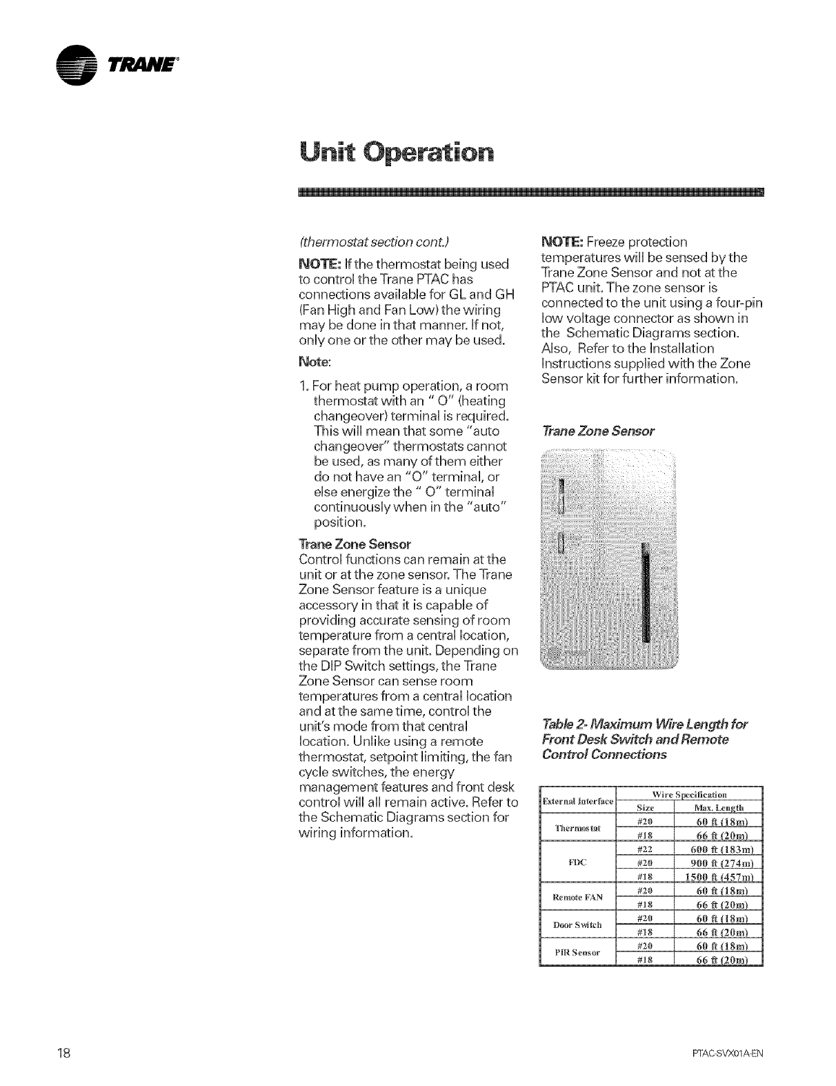
Trane Zone Sensor
ControUfunctions can remain at the
unit or at the zone sensor. The Trane
Zone Sensor feature is a unique
accessory in that it is capaMe of
providing accurate sensing of room
temperature from a central location,
separate from the unit. Depending on
the DIP Switch settings, the Trane
Zone Sensor can sense room
temperatures from a central location
and atthe same time, control the
unit's mode from that central
location. Unlike using a remote
thermostat, setpoint limiting, the fan
cycle switches, the energy
management features and front desk
control will all remain active. Refer to
the Schematic Diagrams section for
wiring information.
temperatures will be sensed by the
Trane Zone Sensor and not at the
PTAC unit. The zone sensor is
connected to the unit using a four-pin
low voltage connector as shown in
the Schematic Diagrams section.
Also, Refer to the Installation
instructions supplied with the Zone
Sensor kit for further information.
TraneZoneSensor
Table 2- Maximum Wire Length for
Front Desk Sw#ch and Remote
ContrM Connections
Rxternai interJ_ce
Thermostat
FDC
Re_riote PAN
Door SvcDch
P_R Sensor
Wire $_cifica_ion
Size Max. Length
#z0 60 fi (18m)
#! 8 66 # (2(hn)
#22 600 ft (183m)
#20 900 _ (274m)
#10 1501_ ft (457mL
#20 60 fi !'l 8m)
#28 66 fl (20m)
#20 60 fl (18m)
#18 66 1_ (2Ore)
#20 60 fl {18m)
#18 66 _ {2Ore)
1_ FI-AC SVX01_EN
lri! liN£ °
Unit Operation
Front Desk Control (FD1, FD2 inputs}
The FD1 and FD2 terminaUs provide
controU inputs for a front desk switch.
Shorting across these two terminaUs
w,HUdisaMe unit operation. The onUy
controUfunction which w,HUremain
active when these terminaUs are
shorted is freeze protection.
Depending on the Fan Cycle DUP
Switch settings, the indoor fan can
operate when the controU is in Front
Desk mode. Any switch which w,HU
produce a short circuit across these
two terminaUs, and when dosed
have less than 200 ohms of contact
resistance can be used as a front
desk switch. Refer to the Schematic
Diagrams section for instructions on
Front Desk Control wiring.
Important Note: Do not apply 24 VAC
across The FD1 and FD2 terminals.
Applying 24VAC to these terminals will
result in failure of the control board.
Shorting these terminals to any other
terminals may also result in control
board failure.
Door Switch/Occupancy Sensor
(DR1, DR2, OCl, 0(;2 inputs}
When the door switch changes state
(the door opens or closes), the unit
control starts a 35 minute timer. If at
the end of the 35 minutes, the
occupancy sensor does not detect
room movement, the unit is in
"Occupied-Standby" Mode. If at any
time during the 35 minutes the
occupancy sensor detects motion,
the unit is in "Occupied" Mode.
Once the room is in an "Occupied"
Mode, the control will ignore the
occupancy sensor until a state
change on the door switch input
occurs. For additional energy
savings, when the unit is in
"Occupied-Standby" mode, the
setpoint temperature is adjusted 4°F
down in the heating mode or 4°F up
in the cooling mode. Refer to the
Schematic Diagrams section for
wiring information. Contact Trane
Sales for more information on
Occupancy Sensors and Door
Switches.
Remote Fan Operation
The Trane PTAC has the ability to
operate a remote fan in conjunction
with the unit's indoor fan. The
remote fan will provide conditioned
air to additional rooms or to areas
that are not well ventilated. The
remote fan will operate anytime the
indoor fan on the PTAC unit is
operating. The remote fan will
require a 24 VAC relay that will
connect to the RF1 and RF2
terminals on the control board user
inputs. This relay can be purchased
from any Trane Parts Center. The
actual remote fan is not supplied by
Trane. Refer to the Schematic
Diagrams section for wiring details.
Vent Lever
Vent Control
A WARNING!
Hazardous Vomtage!
Disconnect aH emectricpower,
including remote disconnects before
servicing. Follow proper lockout/
tagout procedures to ensure the
power can not be inadvertently
energized. Failure to disconnect
power before servicing could result
The vent control allows fresh air to
be drawn into the conditioned area.
This fresh air can provide ventilation
when the indoor fan is operating, but
it will increase the heating or cooling
load and operating costs. To obtain
access to the vent control, remove
the cabinet front and locate the vent
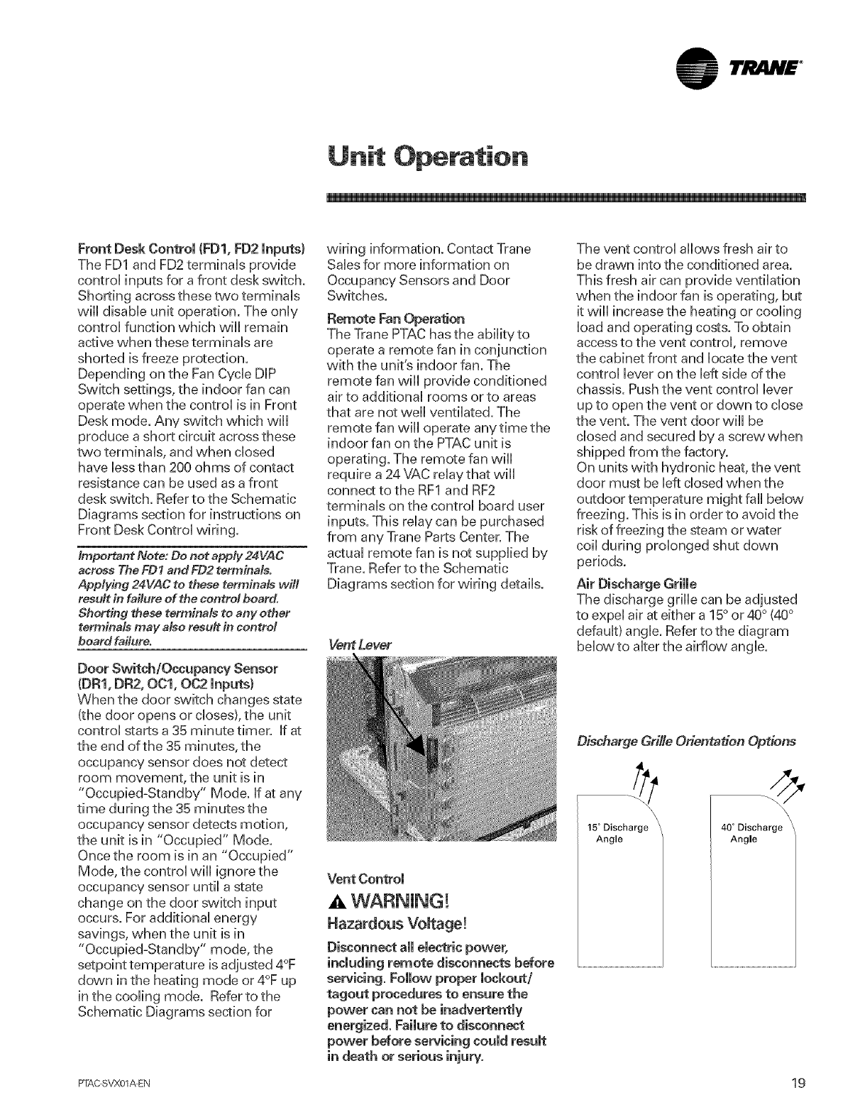
control lever on the left side of the
chassis. Push the vent control lever
up to open the vent or down to close
the vent. The vent door will be
closed and secured by a screw when
shipped from the factory.
On units with hydronic heat, the vent
door must be left closed when the
outdoor temperature might fall below
freezing. This is in order to avoid the
risk of freezing the steam or water
coil during prolonged shut down
periods.
Air Discharge Grille
The discharge grille can be adjusted
to expel air at either a 15° or 40° (40°
default) angle. Refer to the diagram
below to alter the airflow angle.
Discharge Grille Orientation Options
15 ° Discharge
Angle
40 ° Discharge
Angle
PTAC SVX01AEN 19
ltJItlN£ °
Unit Operation
Use the following procedure to
change the angle ofthe
discharge air flow:
1. Remove the front cabinet
2, Position the front cabinet so that
the backside is accessible
Remove the four screws which
secure the discharge air gdlle to
the cabinet front with a Phillips-
Head screwdriver.
.
5.
Rotate the gdlle 180° end4or=end.
Reinstall the screws securing the
discharge air gdlle to the cabinet
front. Reinstall the cabinet front
on the unit.
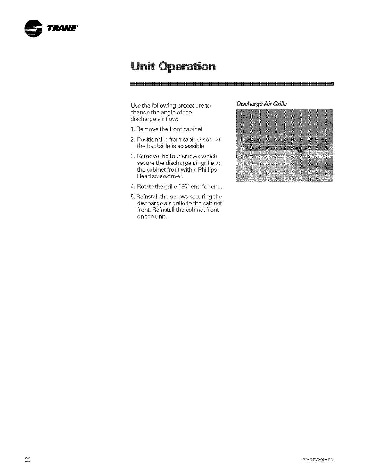
Discharge Air Grille
20 PFAC SVX01_EN
lrjiliN£ °
Chassis
The chassis must be cbaned every
four months or more often asthe
atmospheric conditions require. Use
water and detergent to clean the
basepan, center partition and coils.
The use of harsh cbaning matedaUs
may cause a deterioration of the coil
fins or endpUates.Do not use a high
pressure cbaner as it couM cause
severe damage to the PTACfins and
coils. A hose is okay to use to clean
the coils, but make sure to cover the
controUwith a Manket or pUassticbag
to prevent it from getting wet.
Corrosion Resistant units operating
in harsh atmospheric conditions
must be removed from the sbeve
and cbaned every 3 months in the
same manner as above.
Compressor /Fan Motor
The compressor and fan motor are
hermetbaHy seabd, permanently
Uubricatedand require no additional
oiling.
Cabinet Front
The cabinet front and discharge air
grille can be cleaned with a mild
soap or detergent. Under no
circumstances should hydrocarbon
based cleaners (e.g. acetone,
benzene, naphtha gasoline, etc.} be
used to dean the front or air grilles.
Use care when cleaning the control
area. Do not use an excessively wet
cleaning cloth,
Corrosion Resistant Models
Corrosion resistant models subjected
to harsh seacoast environments must
be removed from the wall sleeve and
completely flushed with clean water
at bast four times a year. The
basepan, center partition, condenser
end plates, and the condenser itself
should be sprayed with clean, fresh
water. Leaving the unit in the sleeve
and simply spraying the outdoor
grille is not sufficient.
mntakeAir Filter
The intake air filter and vent door
filter are both constructed of durable
polypropylene. Before cleaning the
intake filter, turn the unit off by setting
the mode switch to the OFF position.
Filter should be cleaned as required.
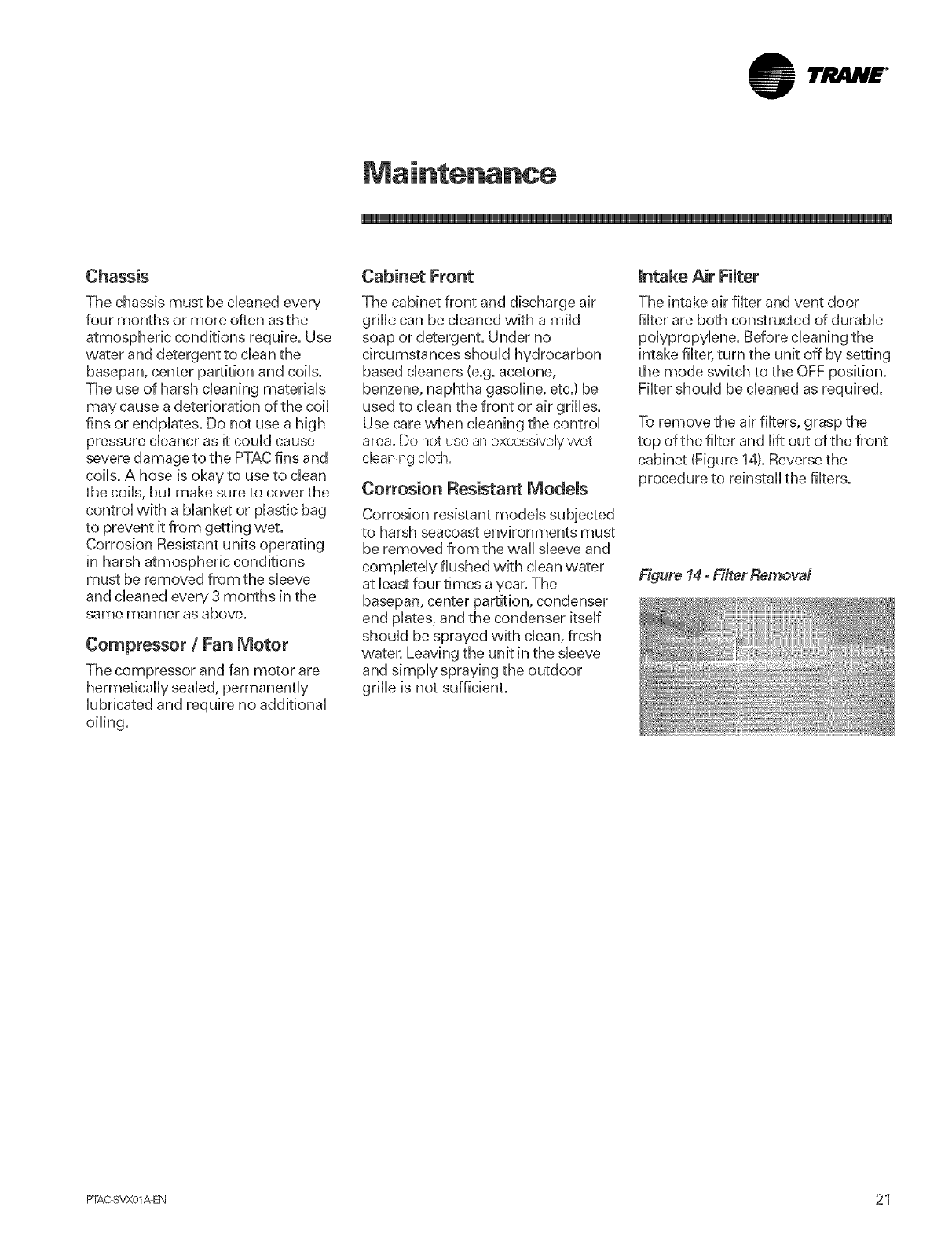
To remove the air filters, grasp the
top of the filter and lift out of the front
cabinet (Figure 14L Reverse the
procedure to reinstall the filters.
Figure 14- Fiiter Removal
PTAC SVX01_EN 21
lr ,tlN£ °
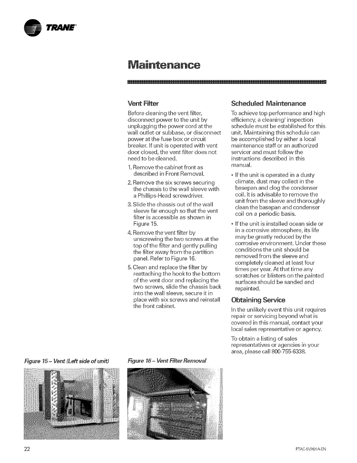
Figure 15- Vent (Left side of unit)
Vent Filter
Before cleaning the vent filter,
disconnect power to the unit by
unplugging the power cord at the
wall outlet or subbase, or disconnect
power at the fuse box or circuit
breaker, if unit is operated with vent
door closed, the vent filter does not
need to be cleaned.
1. Remove the cabinet front as
described in Front Removal.
2. Remove the six screws securing
the chassis to the w,all sleeve vvkh
a Phillips-Head screwdriver.
3. Slide the chassis out of the wall
sleeve far enough so that the vent
filter is accessible as shown in
Figure 15.
4. Remove the vent filter by
unscrewing the two screws at the
top of the filter and gently pulling
the filter away from the partition
panel. Refer to Figure 16.
B.Clean and replace the filter by
reattaching the hookto the bottom
of the vent door and replacing the
two screws, slide the chassis back
into the wail sleeve, secure it in
place with six screws and reinstall
the front cabinet.
Figure 16- Vent Filter Remeva!
ScheduUed Maintenance
To achieve top performance and high
efficiency, a cleaning/inspection
schedule must be established for this
unit. Maintaining this schedule can
be accomplished by either a local
maintenance staff or an authorized
servicer and must followthe
instructions described in this
manual.
, If the unit is operated in a dusty
climate, dust may collect in the
basepan and clog the condenser
coil. it is advisable to remove the
unit from the sleeve and thoroughly
clean the basepan and condenser
coil on a periodic basis.
, If the unit is installed ocean side or
in a corrosive atmosphere, its life
may be greatly reduced bythe
corrosive environment. Under these
conditions the unit should be
removed from the sleeve and
completely cleaned at bast four
times per year. At that time any
scratches or blisters on the painted
surfaces should be sanded and
repainted.
Obtaining Service
in the unlikely event this unit requires
repair or servicing beyond what is
covered in this manual, contact your
local sales representative or agency.
To obtain a listing of sales
representatives or agencies in your
area, please call 800-755-6338.
22 PFAC SVX01_EN
TJ! .N£ °
Contro! Board Diagnostics
important Note: To prevent death,
personal injury or property damage due
to electrical shock, only qualified service
personnel are authorized to use the
diagnostic box or this procedure.
introduction
The Trane PTAC is equipped with a
fauk indicator LED that wHUnotify the
owner when an internaUcontroU
board error has occurred. The LED is
Uocatedon the contrd board itseff
and is covered by the bw-vokage
access cover. Following is a chart
detailing the diagnostic fall codes.
.
ON Normal
OFF No power/faibd board
FaultCodes 4.
1 Compressor Failure
2 Blown Fuse
3 Mode Switch
4 Setpoint Switch
5 Incorrect Thermostat 5.
Wiring 6.
6 indoor Air Thermistor
7 indoor Coil Thermistor
8 Outdoor Air
Thermistor (PTHP Only)
9 Outdoor Coil
Thermistor (PTHP Only) 7.
LED Rash Rate 0,25 sec ON per
flash, 0.25 sec OFF between flashes, 2,00
sec OFF between codes
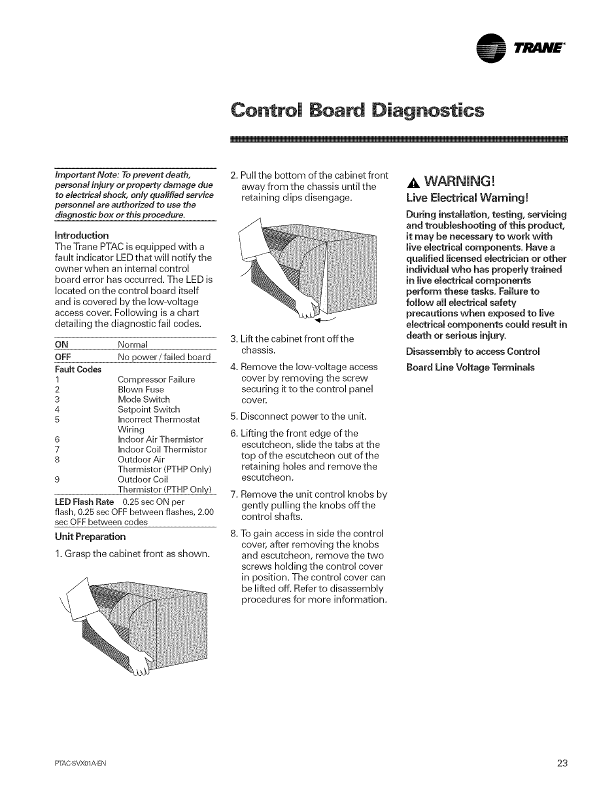
1. Grasp the cabinet front as shown.
2. Puil the bottom of the cabinet front
away from the chassis until the
retaining clips disengage.
Lift the cabinet front off the
chassis.
Remove the low-voltage access
cover by removing the screw
securing it to the control panel
cover.
Disconnect power to the unit.
Lifting the front edge of the
escutcheon, slide the tabs at the
top of the escutcheon out of the
retaining hobs and remove the
escutcheon.
Remove the unit control knobs by
gently pulling the knobs offthe
control shafts.
To gain access in side the control
cover, after removing the knobs
and escutcheon, remove the two
screw's holding the control cover
in position. The control cover can
be lifted off. Refer to disassembly
procedures for more information.
WARNING!
Live Electrical Warning!
installation, testing, servicing
and troubleshooting of this produ_,
it may be necessary to work with
live electrical components. Have a
qualified licensed eie_rician or other
individual who has properly trained
in live electrical components
perform these tasks. Failure to
precautions when exposed to live
eie_rical components could result in
death or serious injury.
Disassembly to access Control
Board Line Voltage Terminals
FTAC SVX01_EN 23
lrJItlN£ °
Refrigeration Syste
Refrigeration System Service
Important Note: Brazing requires high
temperatures. Take precaution to
protect against personal injury or
property damage.
To avoid the risk of fire, the refrigeration
system must be kept free from
contamination due to the presence of
air. Fofiow these instructions exactly.
To avoid the risk of bums, property
damage, personal injury or death, do not
plug in this product or apply power to
the compressor if the compressor
terminal cover has been removed or is
not firmly in place.
Effective July 1,1992 before opening
any refrigerant system it is the
responsibility of the service
technician to capture the refrigerant
for safe disposal.
Refer to the cooling and heater
performance charts in this section
for capacity test procedure.
A step-by=step procedure for
determining source of trouble,
suggested method and normal
values are provided in the Diagnosis
Charts.
Service operations requiring opening
of the hermetically sealed
refrigeration system should be taken
to a weii equipped shop where
special equipment for evacuating,
dehydrating, charging and testing is
available. The following equipment is
necessary:
oNitrogen of no more than 0.0012
grains of moisture.
,Vacuum pump capable of
evacuating to a minimum of 50
microns.
oMicron gauge to check vacuum.
oRefrigerant charging cylinder
accurate to within 1/4 oz.
, Electronic leak detector
, Electrical equipment to test
compressors, capacitors, voltage
relays and overload protectors
oVolt-meter, ammeter, and watt-
meter
, Silver soldering and brazing
equipment - Pinch offtools ¼ in to
5/8 in
, Thermocouple tester
24 PFAC SVX01_EN
1rJ_.NE °
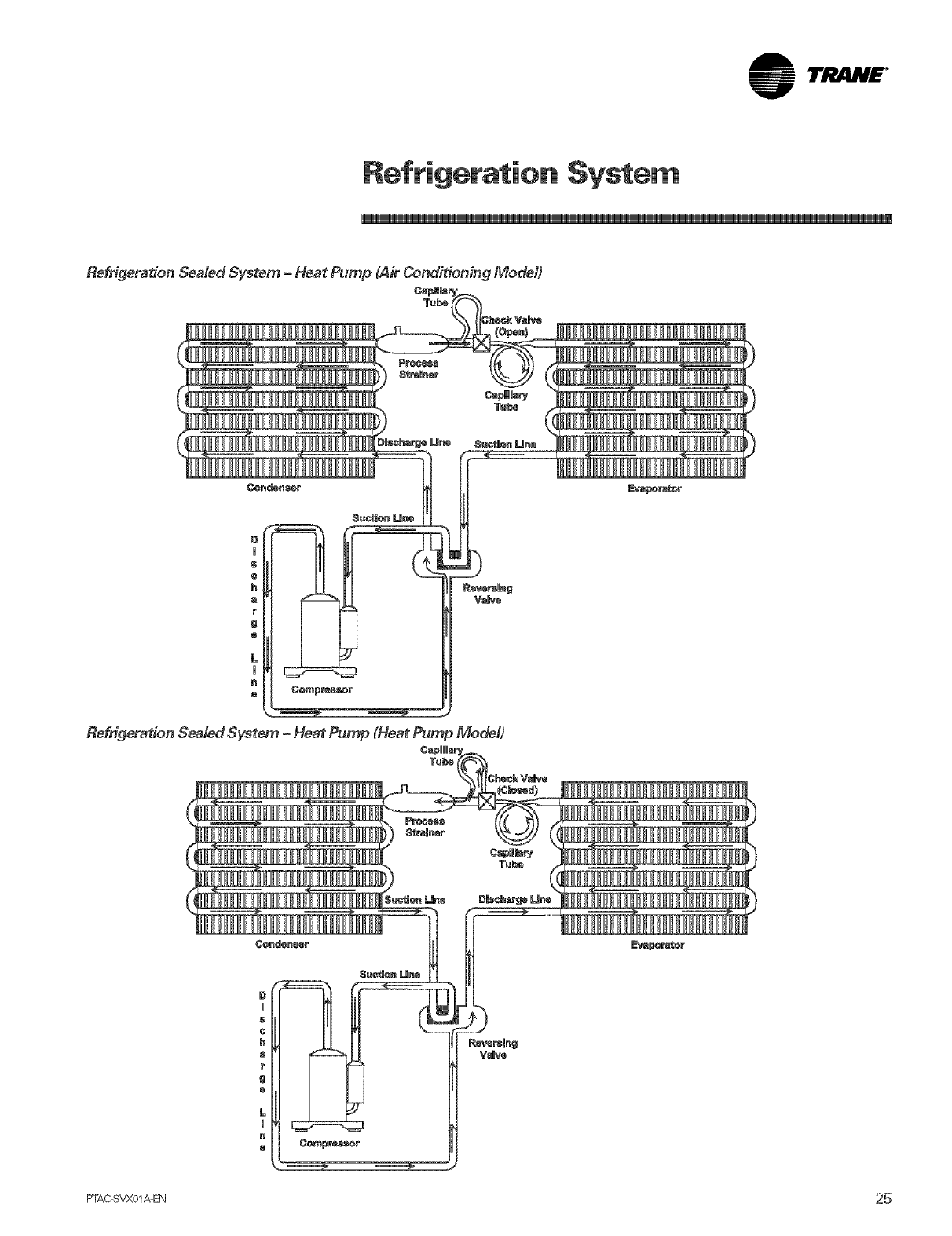
Refrigeration Syste_
RefrigeratJon Sealed System -Heat Pump (Air Conditioning Model)
Tuba
FTAC SVX01A EN 25
lrj lN£ °
Refrigeration Syste
Dehydrating and Evacuating
Refrigeration System
A rather popuUar misconception
exists that since air conditioners
normally operate with a refrigerant
temperature above 32°F,moisture in
the system is harmbss. Nothing
couM be further from the truth.
Oxygen from moisture pUusnormaU
compressor and motor heat reacts
chemically with the refrigerant and
oiUto form corrosive hydrochbrb
and hydrofluoric acids. These acids
contribute to the break down of
motor winding insulation and the
corrosion of compressor working
parts and cause unnecessary
compressor failure. Sludge, which is
a residue of the chemical reaction,
coats all compressor parts, the inside
of refrigerant tubing, and may even
restrict refrigerant flow through the
capillary tube(s).
Refrigerant leaks are best detected
with a halide or electronic leak
detector.
The importance of careful leak
testing cannot be over emphasized.
Undetected leaks invariably lead to
repeated calls and eventually result
in system contamination, restrictions
and burned out compressors.
For a system that contains a
refrigerant charge and is suspected
of having a leak, stop the operation,
check all tubing and fittings. Soap
suds may also be used.
Note: The flame of the halide
detector wiil glow green in the
presence of R22 refrigerant.
Ifa leak is detected, do not attempt
to apply more brazing material to the
joint. Recover the charge, unbraze
the joint, clean and rebraze.
For a system that has been newly
repaired and does not contain a
charge, connect a cylinder of
refrigerant, through a gauge
manifold, to the process tube of the
compressor and liquid line strainer.
Open the valve on the cylinder and
manifold and allow the pressure to
build up within the system. Check for
and handle leaks as described
above.
After the test has been completed,
recover the test charge, evacuate the
system, and recharge with clean
refrigerant.
Brazing
Important Note: Brazing requires high
temperatures. Take precaution to
protect against persona/injury or
property damage.
Satisfactory results require
cleanliness, experience and the use
of proper material and equipment.
The connections to be brazed must
be properly sized, free of rough
edges and clean.
The generally accepted materials
are:
SlL_FOS (Alloy of 15% silver, 80%
copper, 5% phosphorus) is used
without flux on copper to copper. DO
NOT USE FORA COPPERTO STEEL
CONNECT/ON. Recommended heat
is approximately 1400°E
SILVERSOLDER (Alloy of 30% silver,
38% copper, 32% zinc) is used with
fluoride base flux on copper to steel,
brass to copper, steel to steel, brass
to steel. Recommended heat is
approximately 1200°R
26 PTAC SVX01_EN
lt'i! m.H£ °
Refrigeration System
Evacuation
Important Note: To prevent severe
burns, do not allow the sludge or oil to
contact the skin,
Effective July 1,1992. Before opening
any refrigerant system it is the
responsibility of the service
technician to capture the refrigerant
for safe disposal.
This is the most important part
ef the ent{te service pt_edure.
The mile and efficiency of the
equipment is dependent upon
the thoroughness exercised by
the sewiceman when evacuating
air (non_sondensab|es} and
meisturo from the system.
Air in the system causes high
condensing temperature and
pressure, resulting in increased
power input and reduced
performance.
Moisture chemically reacts with the
refrigerant and oil to form corrosive
hydrofluoric and hydrochloric acids.
These attack motor windings and
parts, causing breakdown.
The equipment required to
thoroughly evacuate the system is a
high vacuum pump, capable of
producing a vacuum equivalent to
50 microns, and a thermocoupb
vacuum gauge to give atrue reading
of the vacuum in the system.
Note: Never use the system
compressor as a vacuum pump or
run when under a high vacuum.
Motor damage could occur.
1. Connect the vacuum pump,
vacuum tight manifold set with
high vacuum hoses, thermo-
couple vacuum gauge and
charging cylinder.
2. Connect the low side line to the
process tube of the compressor.
3. Connect the high side line to the
process tube of liquid line strainer.
Note: If either process tube is not
long enough to receive the
compression or flare fitting and still
leave room for a pinch-off, swag the
tube and braze in an extra length of
tubing.
4. Start the vacuum pump and open
shut off valve to the high vacuum
gauge manifold only. After the
compound gauge (low side) has
dropped to approximately 29
inches of vacuum, open the valve
to the vacuum thermocoupb
gauge. See that the vacuum pump
will bank-off to a minimum of 50
microns. A high vacuum pump
can only produce a good vacuum
if its oil is not contaminated.
5. if the vacuum pump is working
properly, close the valve to the
vacuum thermocouple gauge and
open the high and low side valves
orthe high vacuum manifold set.
With the valve on the charging
cylinder closed, open the manifold
valve to the cylinder.
6. Evacuate the system to at bast 29
inches gauge before opening
valve to thermocouple vacuum
gauge.
7. Continue to evacuate to a
minimum of 250 microns. Close
valve pump and watch rate of rise.
if vacuum does not rise above
1500 microns in three minutes,
system can be considered
properly evacuated.
8. If thermocouple vacuum gauge
continues to rise and levels off at
about 5000 microns, moisture and
non-condensables are still
present, if gauge continues to rise
a leak is present. Repair and re-
evacuate.
9. Close valve to thermocouple
vacuum gauge and vacuum
pump. Shut off pump and prepare
to charge.
FrAC SVX01_EN 27
lrjl4N£ °
Refrigeration Syste
Charging
Charge the system with the exact
amount of refrigerant.
Refer to the unit nameplate for the
correct refrigerant charge. An
inaccurately charged system will
cause future problems.
1. When using an ambient
compensated caUibrated charging
cyUinder,allow Uiquid refrigerant
onUyto enter the high side.
2. After the system will take alUit will
take, close the valve on the high
side of the manifold.
Start the system and charge the
balance of the refrigerant though
the low side. Do not charge in a
liquid form.
Close the low side valve on the
manifold and pinch-off both
process tubes. Remove the
manifold set, crimp shut the open
ends of the process tubes and
braze.
5. Recheck for refrigerant leaks.
Refrigerant
Do not use a refrigerant other than
that shown on the unit nameplate.
Ail precautionary measures
recommended by the refrigerant
manufacturers and suppibrs should
be observed.
Une Piercing Valves
Line piercing valves may be used for
diagnosis but are not sukable for
evacuating or charging due to the
minute hobs pierced in the tubing.
Line piercing valves must not be left
on the refrigerant system. The
connection between the valve and
the refrigerant tubing is not
hermetically sealed and will
eventually leak.
Open Lines
During any processing of the
refrigeration system the lines should
never be left open to atmosphere
since water vapor wiil enter and add
to the problem of proper evacuation.
Operating Test
The final step in a successful repair is
an accurate operating test. Follow
the Cooling and Heating
Performance tests provided to make
sure the product is again performing
to design standards.
important Note: Never test operation
without the unit in the wall sleeve, A
serious change in design specifications
for air movement through the
evaporator and condenser
compartments, causing the fan meter to
ever heat and the refrigeration system
to become unbalanced wilt occur when
the unit is net in.a/ted in the wa//
sleeve,
28 PFAC SVX01_EN
lri! m.H£ °
Refrigeration System
A WARNING!
Hazardous Voltage!
Disconnect aH electric power,
including remote disconnects before
servicing. Fefmowproper mockout/
tagout procedures to ensure the
power can not be inadvertently
energized, Failure to disconnect
power before servicing could result
in death or serious injury.
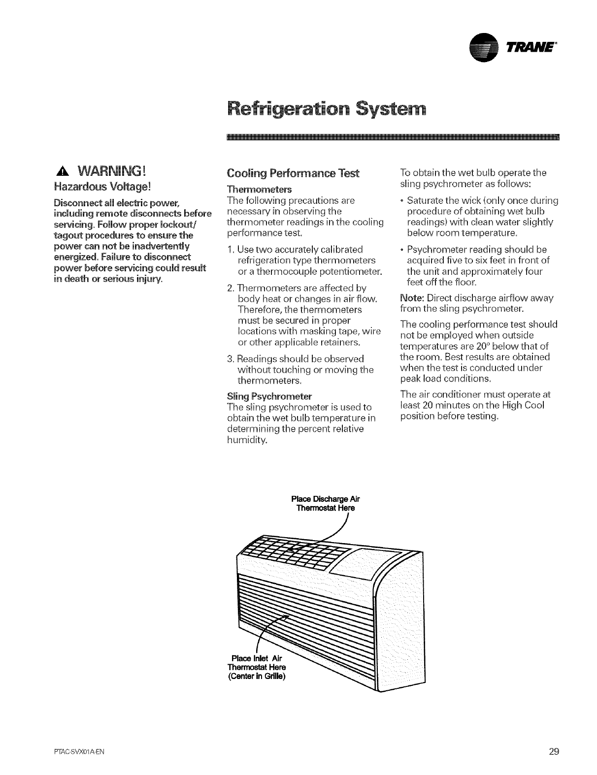
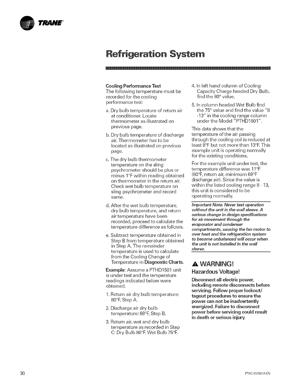
Cooling Performance Test
Thermometers
The following precautions are
necessary in observing the
thermometer readings in the cooling
performance test.
1. Use two accurately calibrated
refrigeration type thermometers
or a thermocouple potentiometer.
Thermometers are affected by
body heat or changes in air flow.
Therefore, the thermometers
must be secured in proper
locations with masking tape, wire
or other applicable retainers.
3. Readings should be observed
without touching or moving the
thermometers.
The sling psychrometer is used to
obtain the wet bulb temperature in
determining the percent relative
humidity.
To obtain the wet bulb operate the
sling psychrometer as follows:
o Saturate the wick (only once during
procedure of obtaining wet bulb
readings) with clean water slightly
below room temperature.
o Psychrometer reading should be
acquired five to six feet in front of
the unit and approximately four
feet off the floor.
Note: Direct discharge airflow away
from the sling psychrometer.
The cooling performance test should
not be employed when outside
temperatures are 20° below that of
the room. Best results are obtained
when the test is conducted under
peak load conditions.
The air conditioner must operate at
least 20 minutes on the High Cool
PlaceDischargeAir
ThermostatHere
PlaceInlet Air
ThermostatHere
(CenterinGrille)
FrAC SVX01_EN 29
lrJ lN£ °
Refrigeration Syste
Cooling Performance Test
The following temperature must be
recorded for the cooling
performance test:
a. Dry bulb temperature of return air
at conditioner. Locate
thermometer as illustrated on
previous page.
b. Dr,/bulb temperature of discharge
air. Thermometer has to be
located as illustrated on previous
page.
The dry bulb thermometer
temperature on the sling
psychrometer should be plus or
minus I°F within reading obtained
on thermometer in the return air.
Check wet bulb temperature on
sling psychrometer and record
same.
d. After the wet bulb temperature,
dry bulb temperature, and return
air temperature have been
recorded, proceed to calculate the
temperature difference as follows.
Subtract temperature obtained in
Step B from temperature obtained
in Step A. The remainder
temperature is used to calculate
from the Cooling Change of
Temperature
Example: Assume a PTHD1501 unit
is under test and the temperature
readings indicated below were
obtained.
.
2.
3.
Return air dry bulb temperature:
8O°F,Step A.
Discharge air dry bulb
temperature: 69°F,Step B.
Return air, wet and dry bulb
temperature as recorded in Step
C: Dry Bulb 8O°F,Wet Bulb 75°R
4. in left hand column of Cooling
Capacity Charge headed Dry Bulb,
find the 80° value.
5. in column headed Wet Bulb find
the 75° value and find the value "8
-13" in the cooling range column
under the Model "PTHD1501".
This data show's that the
temperature of the air passing
through the cooling coil is reduced at
least 8°F but not morethan 13°R This
example unit is operating normally
for the existing conditions.
For the example unit under test, the
temperature difference was 11°F
(SO°F,return air, minimum 69°F
discharge air). Since the value is
within the listed cooling range 8 - 13,
this unit is considered to be
operating normally.
Important Note: Never test operation
w#hout the unit in the wall sleeve. A
serious change in design specifications
for air movement through the
evaporator and condenser
compartments, causing the fan meter to
over heat and the refrigeration system
to become unbalanced will occur when
the unit is not installed in the wag
sleeve.
Hazardous Vomtage!
Disconnect all electric power,
including remote disconnects before
servicing. Follow proper lockout/
ragout procedures to ensure the
power can not be inadvertently
energized. Failure to disconnect
power before servicing could result
30 FrAC SVX01AEN
lri!iliH£ °
Refrigeration System
For The Cooling Wattage Tests the
following additional readings must
be recorded after the unit under test
is interconne_ed with a wattmeter.
oOutdoor air dry bulb temperature.
Avoid direct exposure of
thermometer to sunUight or to hot
condenser discharge air.
oTotal watts input, measured by
wattmeter or caUcuUateby
muUtipUyingappUied vokage by the
unit's amp draw.
Calculating Procedure
Locate the outside air dry buUb
temperature obtained in the first
coUumn of the CooUingWattage
Test.
2. Locate in the second column the
return air wet bulb temperature
obtained in the Cooling
Performance Test.
The total watts input should come
between minimum and
maximum values indicated for
each model.
Assumethat a PTHD1501 is again
under test. Proceed as follows and
observe test readings as
simultaneously as possible.
1. Outdoor air dry bulb temperature
reading - 95°R
2. Check watts input - 1510.
3. Wet bulb temperature as described
in Step C,75°F.
In the column headed Outdoor Air
Dry Bulb Temperature of the Cooling
VVattage Test find the 95°F value.
Read to the right from the 95°F value
and find the room wet bulb
temperature (75°F).
Read to the right front the 75°F W.B.
value in the PTHD1501 column and
note the minimum and maximum
wattage of 1460- 1575.
Since the wattage reading (1510)
obtained in the tess is with in the
prescribed range, the total power
input in watts is considered to be
normal.
Electric Heat Test
For the electric heat test, the
following readings must be recorded
after the unit is interconnected with a
wattmeter or by recording the total
amp draw to the unit.
Note: Cabinet front must be in place
during this test.
oRecord supply voltage to unit.
oOperate unit in highest heat
setting.
oRecord wattage recorded on
wattmeter or total amp draw to
unit.
oRefer to the Electric Heat Capacity
and Electrical Data on page 41
(whichever is applicable for voltage
rating on the unit being tested.)
oThe total watts or amps recorded
should fall with in the minimum
and maximum watts/amps listed
on these charts.
PTAC SVX01_EN 31
lrJItlN£ °
Refrigeration Syste
Assume that a PTHD1501 230/208V
with 3.5 kW eUectricheater is under
test.
1. SuppUyvokage as recorded - 208V.
2. Watts recorded -2750W or Amps
recorded - 13.5 Amps.
Locate the readings UisSedon page
11. You vviHnote that these
readings fall within the voUtage,
watts and amp draw minimum
and maximum ranges Uistedand
therefore the unit heating
performance wouH be considered
normal
Heating Power Consumption Test
For the heating wattage, the
following readings must be recorded
after the unit is interconnected with a
wattmeter.
o Outside coiUinlet air dry bulb
temperature.
o Inside coil inlet air dry bulb
temperature.
o Total watts input measured by
wattmeter.
1. Locate temperature obtained in
Step A of cooling performance
test in first column of Heating
Wattage Chart.
2. Locate in second column the
inside coil inlet dry bulb
temperature.
3. The total watts input should come
between minimum and
maximum values indicated for
each model.
Assume that a PTHD1501 is under
test. Proceed as follows and observe
test readings as simultaneously as
possible.
1. Outside coil inlet dry bulb
temperature readings as
described above: 45°R
2. Check watts input: 1370 W
3. inside coil inbt dry bulb
temperature reading as de scribed
in Step B: 75°R
Read to the right from the 75°inside
coil inlet dry bulb value in the
column and note the minimum and
maximum wattage of 1335 =1470.
Since the wattage reading (1370)
obtained in the test is within the
prescribed range, the total power
input in watts is considered to be
normal.
32 PFAC SVX01_EN
lrl liH£ °
Refrigeration Syste
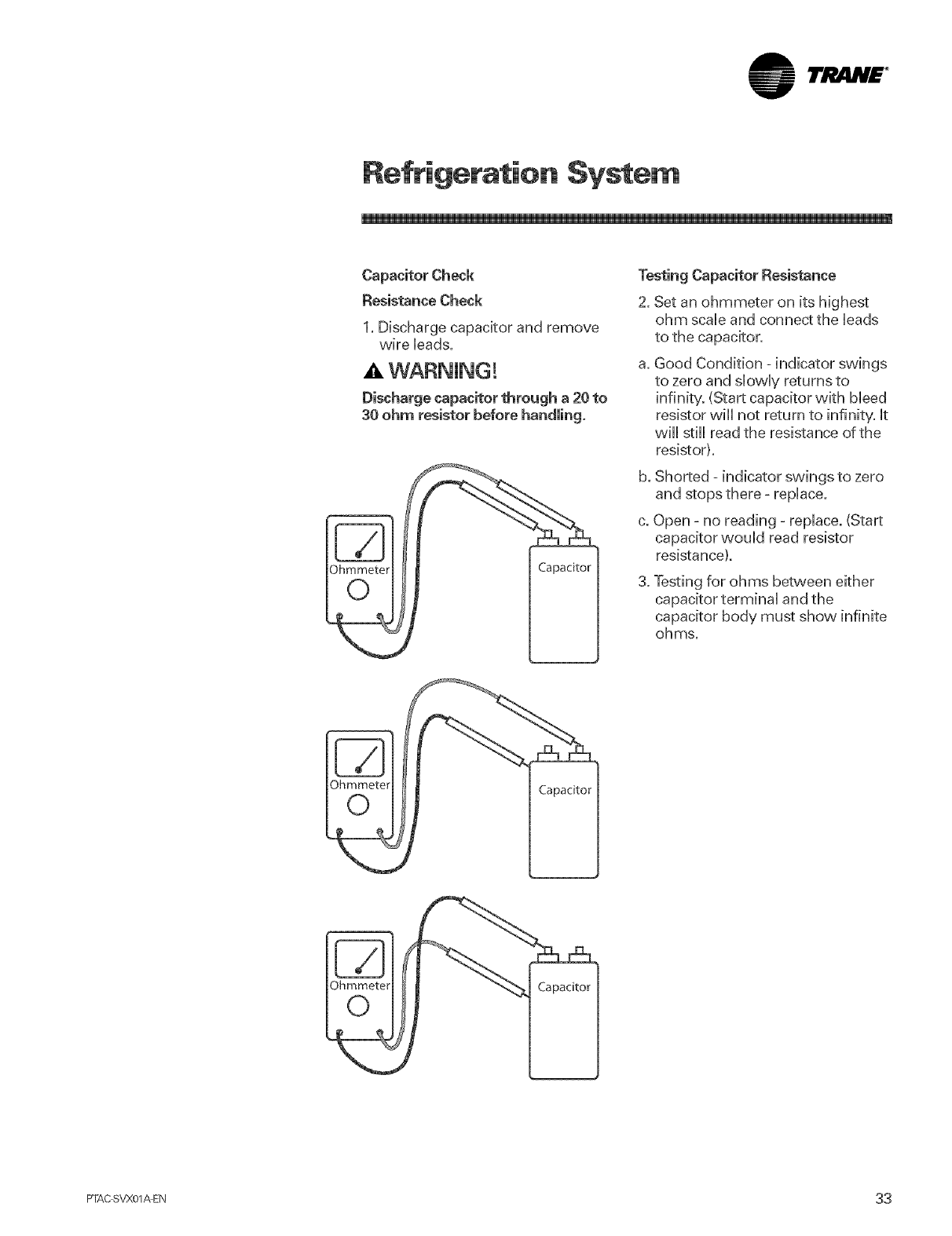
Capacitor Check
Resistance Check
1. Discharge capacitor and remove
wire leads.
WARNING!
Discharge capacitor through a 20 to
30 ohm resistor before handling.
Capacitor
Testing Capacitor Resistance
2. Set an ohmmeter on its highest
ohm scale and connect the leads
to the capacitor.
a. Good Condition - indicator swings
to zero and slowly returns to
infinity. (Start capacitor with bleed
resistor will not return to infinity, it
wHI still read the resistance of the
resistor).
b. Shorted - indicator swings to zero
and stops there- repUace.
c. Open - no reading - replace. (Start
capacitor would read resistor
resistance).
3. Testing for ohms between either
capacitor terminal and the
capacitor body must show infinite
ohms.
Capacitor
Ohmmeter
0Capacitor
PTAC SVX01AEN 33
I'JltlN£ °
Co ponent Tests
A WARNING!
Hazardous Vomtage!
Disconnect all electric power,
including remote disconnects before
servicing. Follow proper lockout/
tagout procedures to ensure the
power can not be inadvertently
energized. Failure to disconnect
power before servicing could result
in death or serious injury.
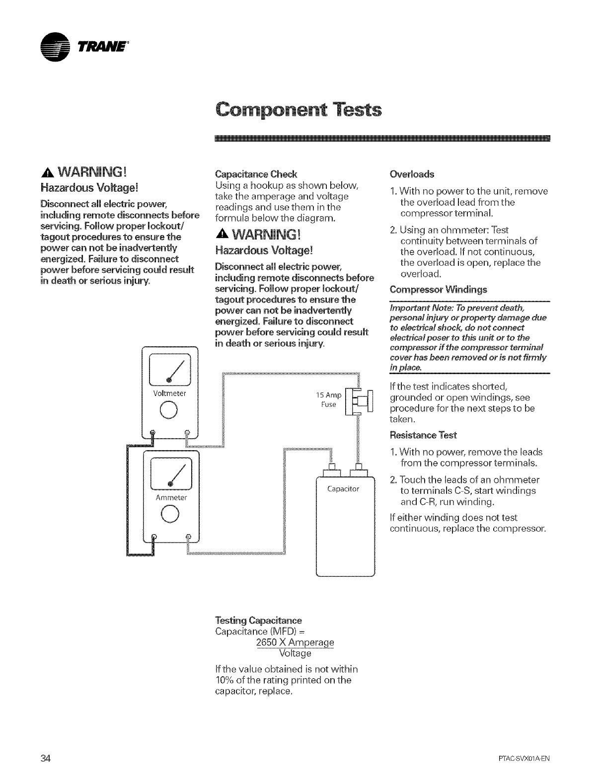
Capacitance Check
Using a hookup as shown below,
take the amperage and voltage
readings and use them in the
formula below the diagram.
A WARNING!
Hazardous Vomtage!
Disconnect all electric power,
including remote disconnects before
servicing, Follow proper lockout/
ragout procedures to ensure the
power can not be inadvertently
energized. Failure to disconnect
power before servicing could result
VoBtmeter
©
_j-
Ammeter
15Amp F] _
Fuse
0
Capacitor
Overloads
1.With no power to the unit, remove
the ovedoad Ueadfrom the
compressor terminal
2. Using an ohmmeter: Test
continuity between terminaUs of
the overload. Ufnot continuous,
the overload is open, replace the
overload.
Compressor Windings
Important Note: To prevent death,
personal injury or property damage due
to electrical shock, do not connect
electrical poser to this unit or to the
compressor if the compressor terminal
cover has been removed or is not firmly
in place.
If the test indicates shorted,
grounded or open windings, see
procedure for the next steps to be
taken.
Resistance Test
1.With no power, remove the leads
from the compressor terminals.
2. Touch the leads of an ohmmeter
to terminals C-S, start windings
and C-R, run winding.
If either winding does not test
continuous, replace the compressor.
Testing Capacitance
Capacitance (MFD) =
2650 X Amperage
Voltage
Ifthe value obtained is not within
10% of the rating printed on the
capacitor, replace.
34 PFAC SVX01/kEN
lri!i4N£ °
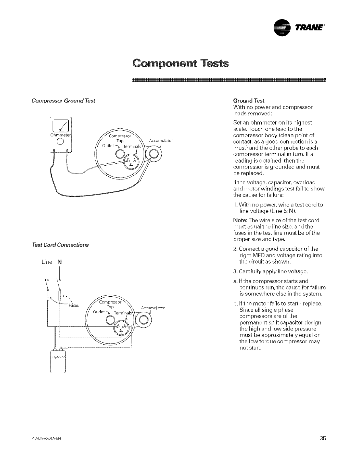
Co ponent Tests
Test Cord Connections
Line N
Ground Test
With no power and compressor
bads removed:
Set an ohmmeter on its highest
scab. Touch one bad to the
compressor body (dean point of
contact, as a good connection is a
must) and the other probe to each
compressor terminaU in turn. if a
reading is obtained, then the
compressor is grounded and must
be replaced.
If the voltage, capacitor, overload
and motor windings test fail to show
the cause for failure:
1. With no power, wire a test cord to
line voltage (Line & N).
Note: The wire size of the test cord
must equal the line size, and the
fuses in the test line must be of the
proper size and type.
2. Connect a good capacitor of the
right MFD and voltage rating into
the circuit as shown.
3. Carefully apply line voltage.
a. if the compressor starts and
continues run, the cause for failure
is somewhere else in the system.
b. If the motor fails to start =replace.
Since all single phase
compressors are of the
permanent split capacitor design
the high and low side pressure
must be approximately equal or
the low torque compressor may
not start.
FTAC SVX01AEN 35
lrJltlH£ °
Component Tests
WARNING !
Hazardous Vomtage!
Disconnect aH electric power,
including remote disconnects before
servicing, Fommowproper mockout/
tagout procedures to ensure the
power can not be inadvertentmy
energized. Failure to disconnect
power before servicing could result
in death or serious iniury.
indoor Coil and indoor Air
Thermistors:
1. Remove the indoor Coil
Thermistor leads from the circuit
board.
2. Check the resistance of the indoor
Coil Thermistor against the tabb
on the next page. The leads of the
ohm meter will need to contact
the ends of the thermistors that
connect to the board.
3. Replace the indoor Coil Thermistor
if it does not test as above.
Outdoor Coil and Outdoor Air
Thermistors:
1. Remove the outdoor coil
thermistor leads from the circuit
board.
2. Check the resistance of the
Outdoor Coil Thermistor against
the table on the next page. The
leads of the ohm meter will need
to contact the ends of the
thermistors that connect to the
board.
3. Replace the outdoor coil
thermistor if it does not test as
above.
Heater Assembly With Power OFF
to the unit and heater:
1. Remove the heaters in question
and visually inspect the element
for broken condition. Refer to the
disassembly procedures for
information on disassembling the
heater.
2. Testthe thermal fuse (one time
fuse). If open, replace the heater
assembly.
Reversing Valve
Occasionally the reversing valve may
stick in the heating or cooling
position or in the mid-operation.
When stuck in the mid-position, part
of the discharge gas from the
compressor is directed back to the
suction side resulting in excessively
high suction pressure.
Checkthe operation of the valve by
starting the system and switching the
operation from COOLING to
HEATING and then backto COOLING.
f no voltage is registered to the coil,
check the operation of the reversing
relay and the continuity of the
connecting wires.
If voltage is registered at the coil, tap
the valve body lightly whib
switching the system from HEATING
to COOLING etc. Ifthis fails to cause
the valve to switch position, remove
the coil connector cap and wiring
and test the continuity of the valve
coil. Ifthe coil does not test
continuous replace it.
Ifthe valve is inoperative, replace.
Replacement of the compressor,
evaporator, condenser, capillary
tubes and reversing valve must be in
accordance with accepted service
practices. These procedures include
a complete evacuation of both high
and low sides, and changing of the
capillary tube assembly whenever
the refrigerant system is opened.
Before replacing a component in the
sealed system, make sure that the
cause for complaint does not lie in
the electrical circuit, control, overload
or is due to some other reason. The
serviceman must be familiar with the
operational characteristics of the
product and should not jump to
conclusions.
Temperature-Actuated Drain Valve
(PTHPOnly}
The Trane PTHPwill be equipped
with a temperature-actuated drain
valve located in the base pan. Asthe
outdoor ambient decreases to 55°F,
the drain valve will begin to open.
The valve will be completely open
when the outdoor ambient
temperature falls to 50° R
Uve Electrical Warning!
installation, testing, servicing
and troubleshooting of this product,
it may be necessary to work with
live electrical components. Have a
qualified licensed electrician or other
individual who has properly trained
in live electrical components perform
these tasks. Failure to follow all
electrical safety precautions when
exposed to live emestrical
components could result in death or
serious injury.
Important Note: Set the temperature
controt a# the way counter-clockwise to
prevent the fan from suddenly coming
on and endangering the servicer's hands.
36 PFAC SVX01_EN
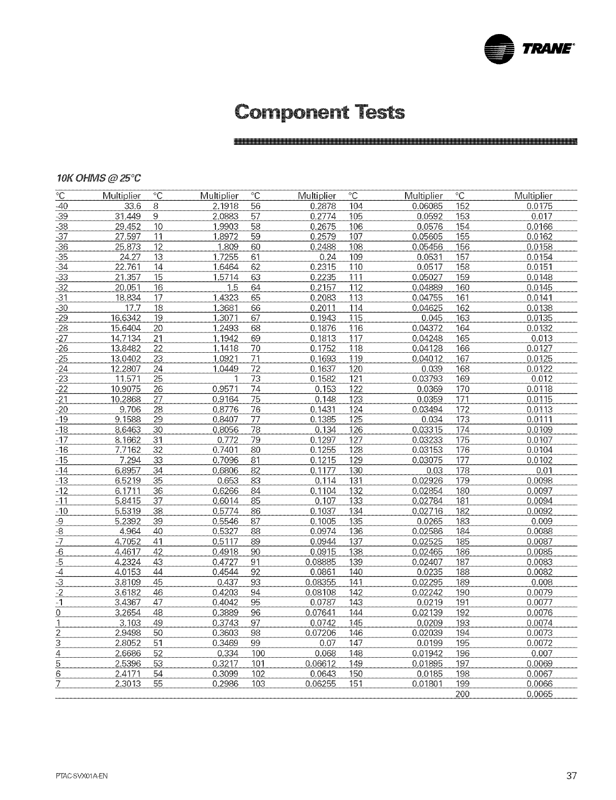
lr,i! a.N£ °
Co ponent Tests
1OKOHMS @ 25°C
°C Multiplier °C Multiplier °C Multiplier °C Multiplier °C Multiplier
-40 33.6 8 2,1918 56 0.2878 104 0.06085 152 0.0175
-39 31.449 9 2=0883 57 &2774 105 0.0592 153 0.017
-38 29,452 10 1.9903 58 0.2675 106 0.0576 154 0.0166
-37 27.597 11 1.8972 59 0,2579 107 0.05605 155 0.0162
-36 25.873 12 1,809 60 0,2488 108 0.05456 156 0.0158
-35 24.27 13 1.7255 61 0.24 109 0.0531 157 0.0164
-34 22,761 14 1.6464 62 0,2315 110 0.0517 158 0.0151
-33 21.357 15 1.5714 63 0,2235 111 0.05027 159 0.0148
-32 20,051 16 1,5 64 0.2157 112 0.04889 160 0.0145
-31 18,834 17 1.4323 65 0.2083 113 0.04755 161 0.0141
-30 17.7 18 1.3681 66 0.2011 114 0.04625 162 0.0138
-29 16.6342 19 1.3071 67 0.1943 115 0.045 163 0.0135
-28 15.6404 20 1.2493 68 0,1876 116 0.64372 164 0.0132
-27 14.7134 21 1.1942 69 0.1813 117 0.64248 165 0.013
-26 13.8482 22 1.1418 70 0.1752 118 0.04128 166 0.0127
-25 13.6402 23 1.0921 71 0.1693 119 0.04012 167 0.0125
-24 12.2807 24 1.0449 72 0,1637 120 0.039 168 0.0122
-23 11.571 25 1 73 0.1582 121 0.03793 169 0.012
-22 10.9075 26 0,9571 74 0.153 122 0.0369 170 0.0118
-21 10.2868 27 0,9164 75 0.148 123 0.0359 171 0.0115
-20 9.706 28 0.8776 76 0,1481 124 0.03494 172 0.0113
-19 9.1588 29 0.8407 77 0,1385 125 0.034 173 0.0111
-18 8.6463 30 0,8056 78 0.134 126 0.03315 174 0.0109
-17 8.1662 31 0.772 79 0.1297 127 0.03233 175 0.0107
-16 7.7162 32 0.7401 80 0.1255 128 0.03153 176 0.0104
-15 7.294 33 0,7096 81 0,1215 129 0.03075 177 0.0102
-14 6.8957 34 0.6806 82 &1177 130 0.03 178 0.01
-13 6,5219 35 0.653 83 0,114 131 0,02926 179 0,0098
-12 6.1711 36 0,6266 84 0,1104 132 0.02854 180 0.0097
ql 5.8415 37 0,6014 85 0.107 133 0.02764 181 0.0094
-10 5.5319 38 0.5774 86 0,1037 134 0.02716 182 0.0092
-9 5.2392 39 0.5546 87 0.1005 135 0.0265 183 0.009
-8 4.964 40 0,5327 88 0,0974 136 0.02586 184 0.0088
-7 4.7052 41 0,5117 89 0.0944 137 0.02525 185 0.0087
-6 4.4617 42 0.4918 90 0.0915 138 0.02465 186 0.0085
-5 4.2324 43 0.4727 91 0.08885 139 0.02407 187 0.0083
-4 4.0153 44 0.4544 92 0,0861 140 0.0235 188 0.0082
-3 3.8109 45 0,437 93 0.08355 141 0.02295 189 0.008
-2 3.6182 46 0.4203 94 0.08108 142 0.02242 190 0.0079
-1 3.4867 47 0.4042 95 0,0787 143 0.0219 191 0,0077
0 3.2654 48 0,3889 96 0.07641 144 0.02139 192 0.0076
1 3.103 49 0,3743 97 0,0742 145 0.0209 193 0.0074
2 2.9498 50 0,3603 98 0.07206 146 0.02039 194 0.0073
3 2.8052 51 0.3469 99 0.07 147 0.0199 195 0.0072
4 2.6686 52 0.334 100 0.068 148 0.01942 196 0.007
5 2.5396 53 0,3217 101 0.06612 149 0.01895 197 0.0069
6 2.4171 54 0.3099 102 0,0648 150 0.0185 198 0.0067
7 2.3013 55 02986 103 0.06255 151 0.01801 199 0.0066
200 0.0065
FTAC SVX01AEN 37
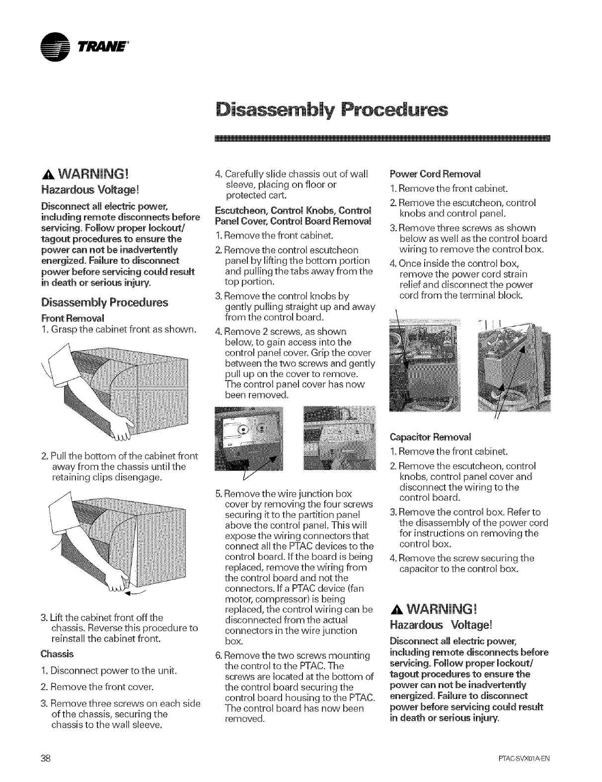
lrJ lN£ °
Disassembly Procedures
A WARNING!
Hazardous Voltage!
Disconnect aH emectricpower,
including remote disconnects before
servicing. Follow proper lockout/
tagout procedures to ensure the
power can not be inadvertently
energized. Faimureto disconnect
power before servicing coumdresumt
Disassembly Procedures
Front Removam
1. Grasp the cabinet front as shown.
4. Carefully slide chassis out of wall
sleeve, placing on floor or
protected cart.
Escutcheon, Control Knobs, Control
Panel Cover, Controm Board Removam
1. Remove the front cabinet.
2. Remove the control escutcheon
pane[ by lifting the bottom portion
and pulling the tabs away from the
top portion.
3. Remove the control knobs by
gently pulling straight up and away
from the control board.
Remove 2 screws, as shown
below, to gain access into the
control panel cover. Grip the cover
between the two screws and gently
pull up on the cover to remove.
The control panel cover has now
been removed.
Power Cord Removal
1.Remove the front cabinet.
2. Remove the escutcheon, control
knobs and control panel.
3. Remove three screws as shown
below as well as the control board
wiring to remove the control box.
4. Once inside the control box,
remove the power cord strain
relief and disconnect the power
cord from the terminal block.
2. Pu[[the bottom of the cabinet front
away from the chassis until the
retaining clips disengage.
3. Lift the cabinet front off the
chassis. Reverse this procedure to
reinstall the cabinet front.
Chassis
1. Disconnect power to the unit.
2. Remove the front cover.
3. Remove three screws on each side
of the chassis, securing the
chassis to the wall sleeve.
Remove the wire junction box
cover by removing the four screws
securing it to the partition pane[
above the control panel. This will
expose the wiring connectors that
connect all the PTAC devices to the
control board. Ifthe board is being
replaced, remove the wiring from
the control board and not the
connectors. If a PTACdevice (fan
motor, compressor) is being
replaced, the control wiring can be
disconnected from the actual
connectors in the wire junction
box.
Remove the two screws mounting
the control to the PTAC.The
screws are located at the bottom of
the control board securing the
control board housing to the PTAC.
The control board has now been
removed.
1.Remove the front cabinet.
2. Remove the escutcheon, control
knobs, control panel cover and
disconnect the wiring to the
control board.
3. Remove the control box. Refer to
the disassembly of the power cord
for instructions on removing the
control box.
4. Remove the screw, securing the
capacitor to the control box.
Hazardous Vomtage!
Disconnect all electric power,
including remote disconnects before
servicing. Follow proper lockout/
ragout procedures to ensure the
power can not be inadvertently
energized. Failure to disconnect
power before servicing could result
38 FFAC SVX01AEN
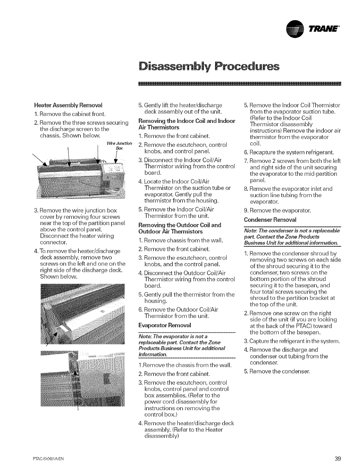
lri!i4H£ °
Disassembly Procedures
Heater AssemMy Removal
1. Remove the cabinet front.
2. Remove the three screws securing
the discharge screen to the
chassis. Shown below.
Wire Junction
Box
3. Remove the wire junction box
cover by removing four screws
near the top of the partition panel
above the control panel.
Disconnect the heater wiring
connector.
4. To remove the heater/discharge
deck assembly, remove two
screws on the left and one on the
right side of the discharge deck.
Shown below.
5. Gently lift the heater/discharge
deck assembly out of the unit.
Removing the indoor Coil and indoor
Air Thermistors
1. Remove the front cabinet.
2. Remove the escutcheon, control
knobs, and control panel.
3. Disconnect the indoor CoWAir
Thermistor wiring from the control
board.
4. Locate the indoor Coil/Air
Thermistor on the suction tube or
evaporator. Gently pull the
thermistor from the housing.
5. Remove the indoor Coil/Air
Thermistor from the unit.
Removing the Outdoor Coil and
Outdoor Air Thermistors
1. Remove chassis from the wall.
2. Remove the front cabinet.
3. Remove the escutcheon, control
knobs, and the control panel.
4. Disconnect the Outdoor Coil/Air
Thermistor wiring from the control
board.
5. Gently pull the thermistor from the
housing.
6. Remove the Outdoor Coil/Air
Thermistor from the unit.
Evaporator Removal
Note: The evaporator is not a
replaceable part. Contact the Zone
Produdts Business Unit for additionM
information.
1.Remove the chassis from the wall.
2. Remove the front cabinet.
Remove the escutcheon, control
knobs, control panel and control
box assemblies. (Refer to the
power cord disassembly for
instructions on removing the
control box.)
4. Remove the heater/discharge deck
assembly. (Refer to the Heater
disassembly)
5. Remove the indoor Coil Thermistor
from the evaporator suction tube.
(Refer to the indoor Coil
Thermistor disassembly
instructions) Remove the indoor air
thermistor from the evaporator
coil.
6. Recapture the system refrigerant.
7. Remove 2 screws from both the left
and right side of the unit securing
the evaporator to the mid-partition
panel.
8. Remove the evaporator inlet and
suction line tubing from the
evaporator.
9. Remove the evaporator.
Condenser Removal
Note: The condenser is not a rep/aceaMe
part. Contact the Zone Products
Business Unit for additionM information.
1. Removethe condenser shroud by
removing two screws on each side
of the shroud securing it to the
condenser, two screws on the
bottom portion of the shroud
securing it to the basepan, and
four total screws securing the
shroud to the partition bracket at
the top of the unit.
2. Remove one screw, on the right
side ofthe unit (if you are looking
at the back of the PTAC)toward
the bottom of the basepan.
3. Capture the refrigerant in the system.
4. Remove the discharge and
condenser out tubing from the
condenser.
5. Remove the condenser.
PTAC SVX01_EN 39
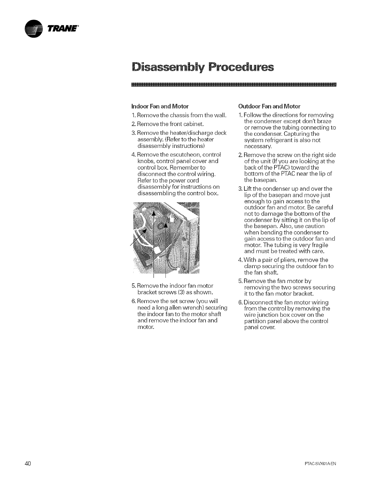
I'JltlN£ °
Disassembly Procedures
indoor Fan and Motor
1. Remove the chassis from the wall.
2. Remove the front cabinet.
Remove the heater/discharge deck
assemMy. (Refer to the heater
disassemMy instructions)
Remove the escutcheon, controU
knobs, controU paneUcover and
controU box. Remember to
disconnect the controUvvMng.
Refer to the power cord
disassemMy for instructions on
disassemMing the controUbox.
5. Remove the indoor fan motor
bracket screws (3) as shown.
6. Remove the set screw (you wHU
need a long allen wrench) securing
the indoor fan to the motor shaft
and remove the indoor fan and
motor.
Outdoor Fan and Motor
1.FoHowthe directions for removing
the condenser except don't braze
or remove the tubing connecting to
the condenser. Capturing the
system refrigerant is also not
necessary.
2. Remove the screw on the right side
of the unit (If you are looking atthe
back of the PTAC)toward the
bottom of the PTACnear the lip of
the basepan.
3. Lift the condenser up and over the
lip of the basepan and move just
enough to gain access to the
outdoor fan and motor. Be careful
not to damage the bottom of the
condenser by sitting it on the lip of
the basepan. Also, use caution
when bending the condenser to
gain access to the outdoor fan and
motor. The tubing is very fragile
and must be treated with care.
4.With a pair of pliers, remove the
clamp securing the outdoor fan to
the fan shaft.
5. Remove the fan motor by
removing the two screws securing
it to the fan motor bracket.
6. Disconnect the fan motor wiring
from the control by removing the
wire junction box cover on the
partition panel above the control
panel cover.
40 PFAC SVX01_EN
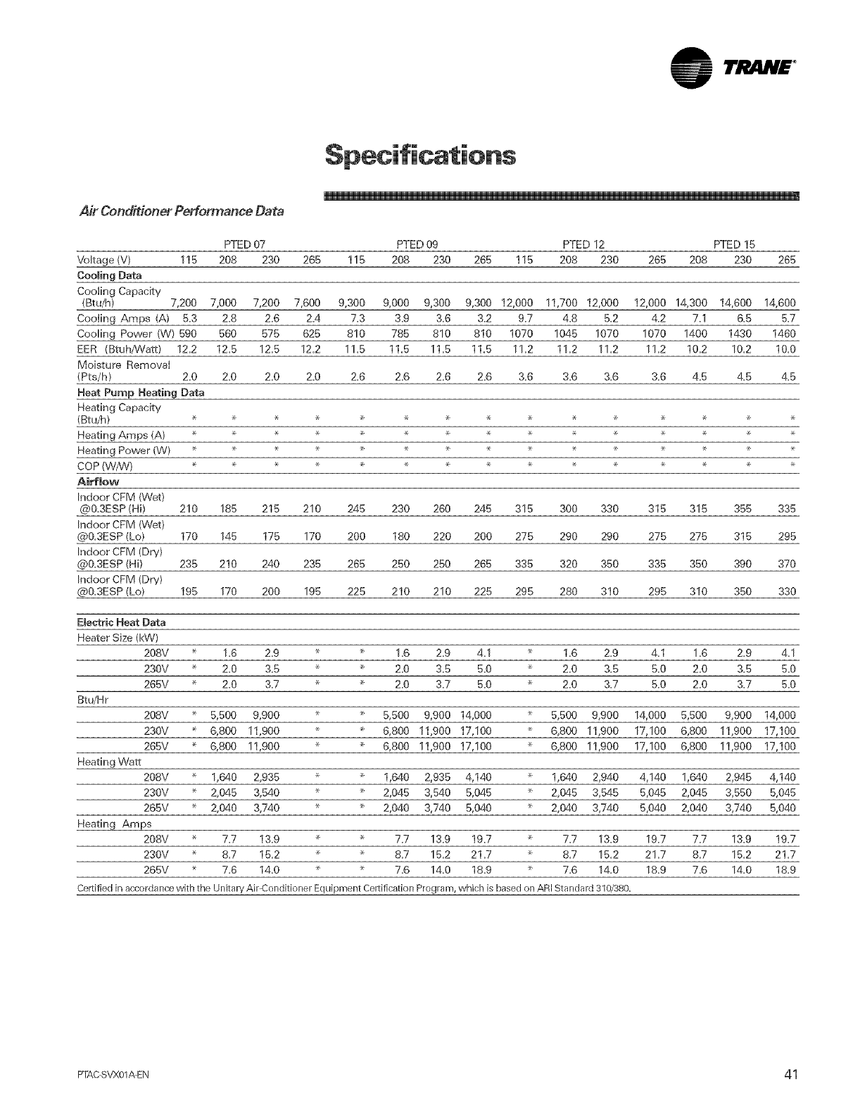
Air Conditioner Performance Data
PTED 07 PTED 09 PTED 12 PTED 15
Voltage (V) 115 208 230 265 115 208 230 265 116 208 230 265 208 230 265
CoomingData
Coo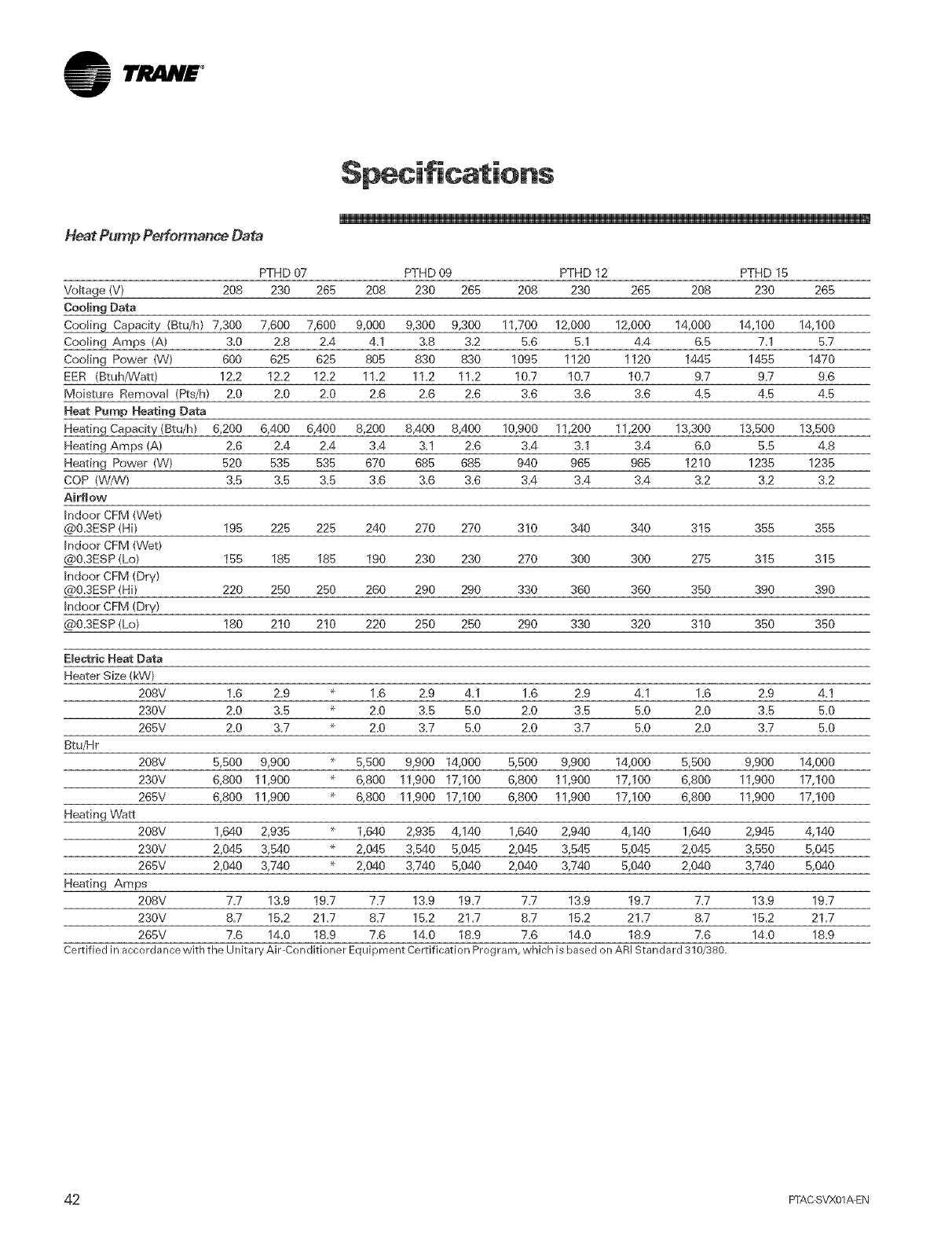
1rP,AN£ °
Heat Pump Performance Data
"I
PTHD 07 PTHD 09 PTHD 12 PTHD 15
Vokage {V) 208 230 265 208 230 265 208 230 265 208 230 265
Cooming Data
Cooling Capacity (Btu/h} 7,300 7,600 7,600 9,000 9,300 9,300 11,700 12,000 12,000 14,000 14,100 14,100
Cooling Amps (A) 3.0 2.8 2.4 4.1 3.8 3.2 5.6 5.1 4.4 6.5 7.1 5.7
Cooling Power (W} 600 625 625 805 830 830 1095 1120 1120 1445 1455 1470
EER (Btuh/Watt) 12.2 12.2 12.2 11.2 11.2 11.2 10.7 10.7 10.7 9.7 9.7 9.6
Mo[sWre Removal {Pts/h) 2.0 2.0 2.0 2.6 2.6 2.6 3.6 3.6 3.6 4.5 4.5 4.5
Heat Pump Heating Data
Heating Capacity(Btu/h} 6,200 6,400 6,400 8,200 8,400 8,400 10,900 11,200 11,200 13,300 13,500 13,500
Heating Amps (A) 2.6 2.4 2.4 3.4 3.1 2.6 3.4 3.1 3.4 6.0 5.5 4.8
Heating Power (W) 520 535 535 670 685 685 940 965 965 1210 1235 1235
COP (W/W) 3.5 3.5 3.5 3.6 3.6 3.6 3.4 3.4 3.4 3.2 3.2 3.2
Airflow
Indoor CFM (Wet}
@0.3ESP (Hi} 195 225 225 240 270 270 310 340 340 315 355 355
Indoor CFB,!(Wet)
@0.3ESP (Lo) 155 185 185 190 230 230 270 300 300 275 315 315
Indoor CFM (Dry}
@0.3ESP (Hi} 220 250 250 260 290 290 330 360 360 350 390 390
Indoor CFM (Dry}
@0.3ESP (Lo) 180 210 210 220 250 250 290 330 320 310 350 350
Ele_rie Heat Data
Heater Size (kW)
208V 1.0 2.9 _ 1.6 2.9 4.1 1.6 2.9 4.1 1.6 2.9 4.1
230V 2.0 3.5 _ 2.0 3.5 5.0 2.0 3.5 5.0 2.0 3.5 5.0
265V 2.0 3.7 _ 2.0 3.7 5.0 2.0 3.7 5.0 2.0 3.7 5.0
Btu/Hr
208V 5,500 9,900 _ 5,500 9,900 14,000 5,500 9,900 14,000 5,500 9,900 14,000
230V 6,800 11,900 ÷ 6,800 11,900 17,100 6,800 11,900 17,100 6,800 11,900 17,100
265V 6,800 11,900 ÷ 6,800 11,900 17,100 6,800 11,900 17,100 6,800 11,900 17,100
Heating Watt
208V 1,640 2,935 _ 1,640 2,935 4,140 1,640 2,940 4,140 1,640 2,945 4,140
230V 2,045 3,540 ÷ 2,045 3,540 5,045 2,045 3,545 5,045 2,045 3,550 5,045
265V 2,040 3,740 _ 2,040 3,740 5,040 2,040 3,740 5,040 2,040 3,740 5,040
Heating Amps
208V 7.7 13.9 19.7 7.7 13.9 19.7 7.7 13.9 19.7 7.7 13.9 19.7
230V 8.7 15.2 21.7 8.7 15.2 21.7 8.7 15.2 21.7 8.7 15.2 21.7
265V 7.6 14.0 18.9 7.6 14.0 18.9 7.6 14.0 18.9 7.6 14.0 18.9
Celtified in accordance with the Unitary Air Conditioner Equipment Certification Program, which is based on ARI Standard 310/380.
42 FFAC SVX01/kEN
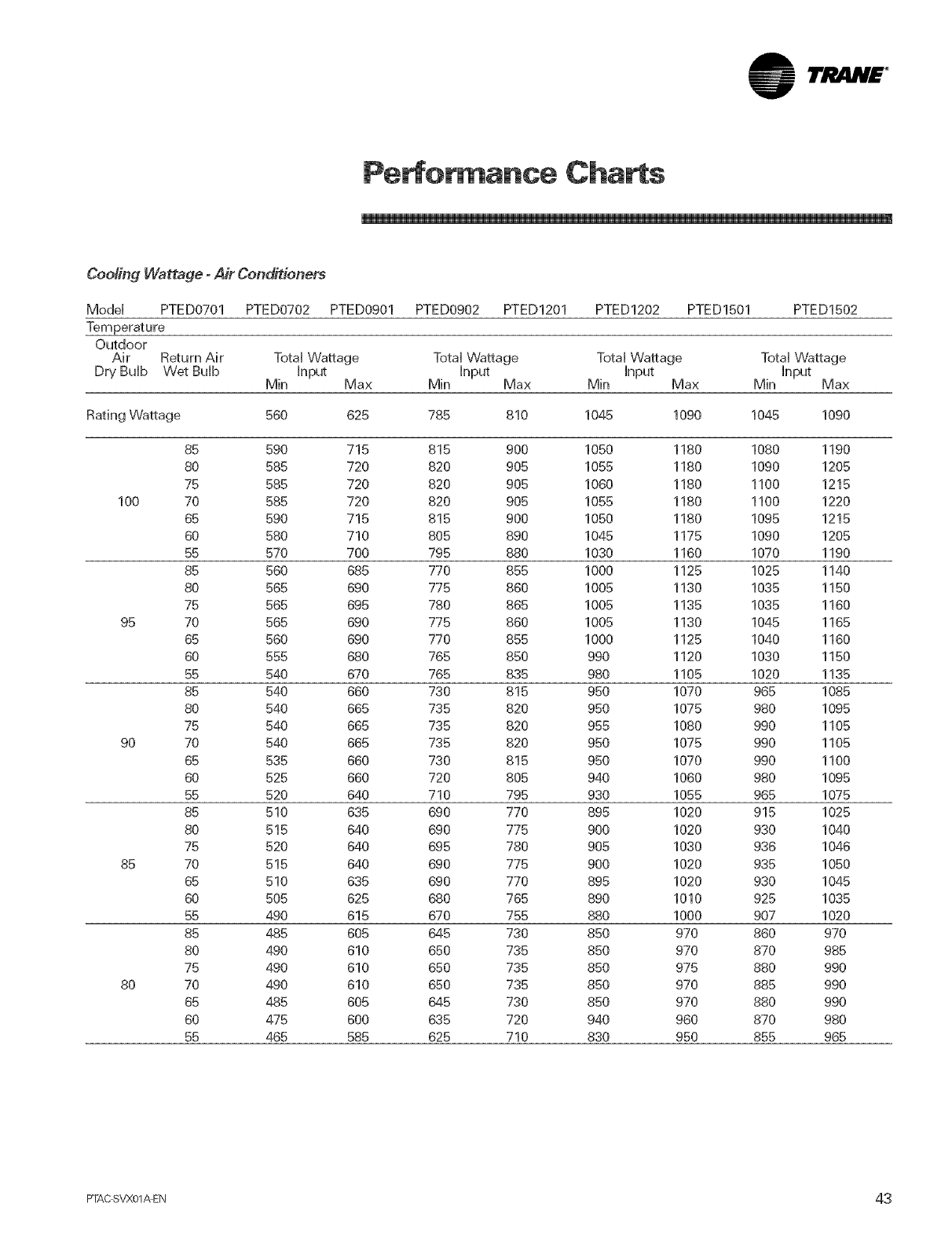
lri! liH£ °
Pe ot ance Charts
Cooling Wattage -Air Conditioners
Modei PTED0701 PTED0702 PTED0901 PTED0902 PTED1201 PTED1202 PTED1501 PTED1502
Temperature
Outdoor
Air Return Air Total Wattage Total Wattage Total Wattage Total Wattage
Dry Bulb Wet Bulb input input input input
Min Max Min Max Min Max Min Max
Rating Wattage 560 625 785 810 1045 1090 1045 1090
85 590 715 815 900 1050 1180 1080 1190
80 585 720 820 905 1055 1180 1090 1205
75 585 720 820 905 1060 1180 1100 1215
100 70 585 720 820 905 1055 1180 1100 1220
65 590 715 815 900 1050 1180 1095 1215
60 580 710 805 890 1045 1175 1090 1205
55 570 700 795 880 1030 1160 1070 1190
85 560 685 770 855 1000 1125 1025 1140
80 565 690 775 860 1005 1130 1035 1150
75 565 695 780 865 1005 1135 1035 1160
95 70 565 690 775 860 1005 1130 1045 1165
65 560 690 770 855 1000 1125 1040 1160
60 555 680 765 850 990 1120 1030 1150
55 540 670 765 835 980 1105 1020 1135
85 540 660 730 815 950 1070 965 1085
80 540 665 735 820 950 1075 980 1095
75 540 665 735 820 955 1080 990 1105
90 70 540 665 735 820 950 1075 990 1105
65 535 660 730 815 950 1070 990 1100
60 525 660 720 805 940 1060 980 1095
55 520 640 710 795 930 1055 965 1075
85 510 635 690 770 895 1020 915 1025
80 515 640 690 775 900 1020 930 1040
75 520 640 695 780 905 1030 936 1046
85 70 515 640 690 775 900 1020 935 1050
65 510 635 690 770 895 1020 930 1045
60 505 625 680 765 890 1010 925 1035
55 490 615 670 755 880 1000 907 1020
85 485 605 645 730 850 970 860 970
80 490 610 650 735 850 970 870 985
75 490 610 650 735 850 975 880 990
80 70 490 610 650 735 850 970 885 990
65 485 605 645 730 850 970 880 990
60 475 600 635 720 940 960 870 980
55 465 585 625 710 830 950 855 965
PTAC SVX01_EN 43
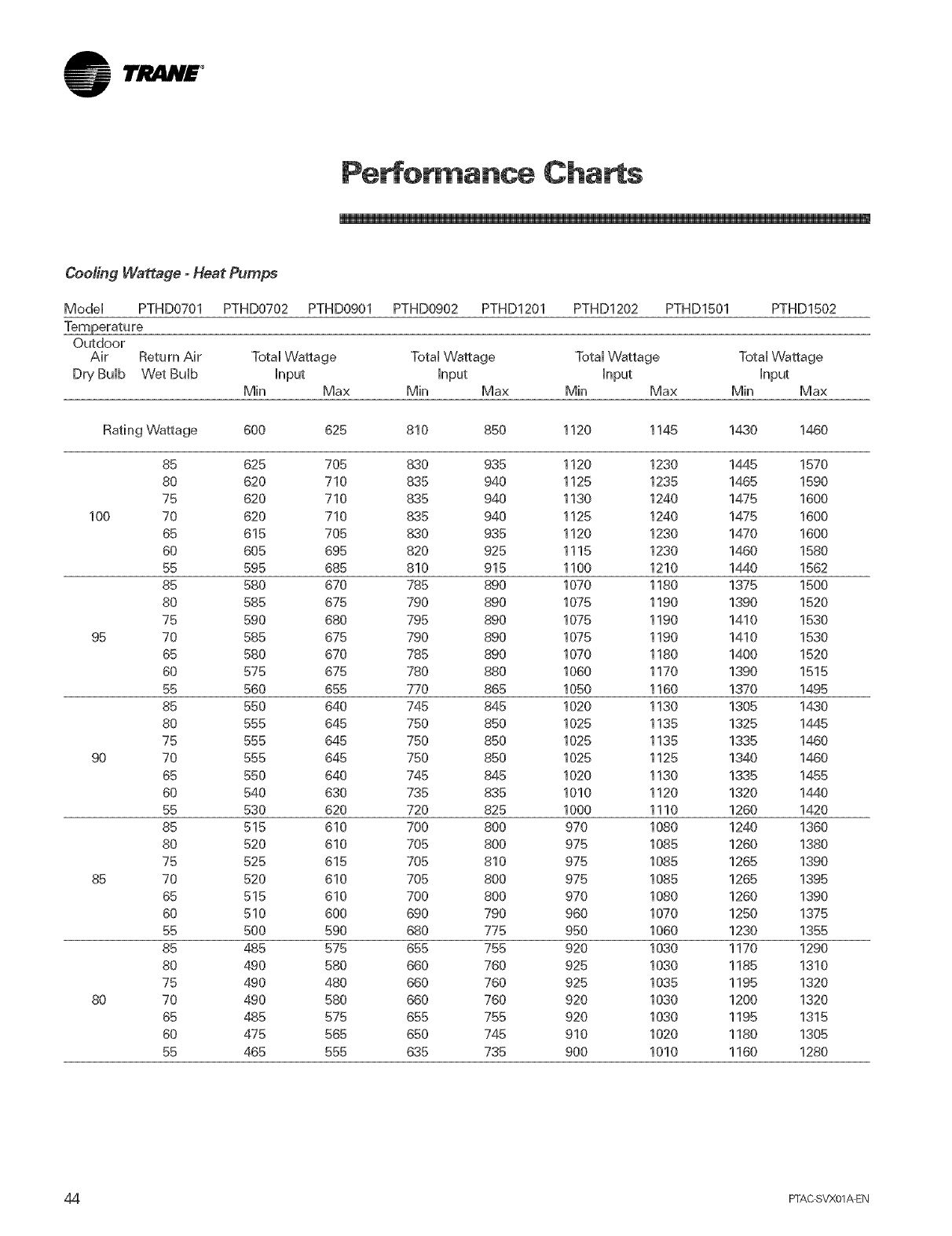
TJ IN£ °
Pe :or ance Charts
CoMing Wattage -Heat Pumps
ModeH PTHD0701 PTHD0702 PTHD0901 PTHD0902 PTHD1201 PTHD1202 PTHD1501 PTHD1502
Outdoor
Air Return Air Total Wattage Total Wattage Total Wattage Total Wattage
Dry BuHb Wet BuHb hput hput hput hput
Min Max Min Max Min Max Min Max
Rating Wattage 600 625 810 850 1120 1145 1430 1460
85 625 705 830 935 1120 1230 1445 1570
80 620 710 835 940 1125 1235 1465 1590
75 620 710 835 940 1130 1240 1475 1600
100 70 620 710 835 940 1125 1240 1475 1600
65 615 705 830 935 1120 1230 1470 1600
60 605 695 820 925 1115 1230 1460 1580
55 595 685 810 915 1100 1210 1440 1562
85 580 670 785 890 1070 1180 1375 1500
80 585 675 790 890 1075 1190 1390 1520
75 590 680 795 890 1075 1190 1410 1530
95 70 585 675 790 890 1075 1190 1410 1530
65 580 670 785 890 1070 1180 1400 1520
60 575 675 780 880 1060 1170 1390 1515
55 560 655 770 865 1050 1160 1370 1495
85 550 640 745 845 1020 1130 1305 1430
80 555 645 750 850 1025 1135 1325 1445
75 555 645 750 850 1025 1135 1335 1460
90 70 555 645 750 850 1025 1125 1340 1460
65 550 640 745 845 1020 1130 1335 1455
60 540 630 735 835 1010 1120 1320 1440
55 530 620 720 825 1000 1110 1260 1420
85 515 610 700 800 970 1080 1240 1360
80 520 610 705 800 975 1085 1260 1380
75 525 615 705 810 975 1085 1265 1390
85 70 520 610 705 800 975 1085 1265 1395
65 515 610 700 800 970 1080 1260 1390
60 510 600 690 790 960 1070 1250 1375
55 500 590 680 775 950 1060 1230 1355
85 485 575 655 755 920 1030 1170 1290
80 490 580 660 760 925 1030 1185 1310
75 490 480 660 760 925 1035 1195 1320
80 70 490 580 660 760 920 1030 1200 1320
65 485 575 655 755 920 1030 1195 1315
60 475 565 650 745 910 1020 1180 1305
55 465 555 635 735 900 1010 1160 1280
44 FTAC SVX01_EN
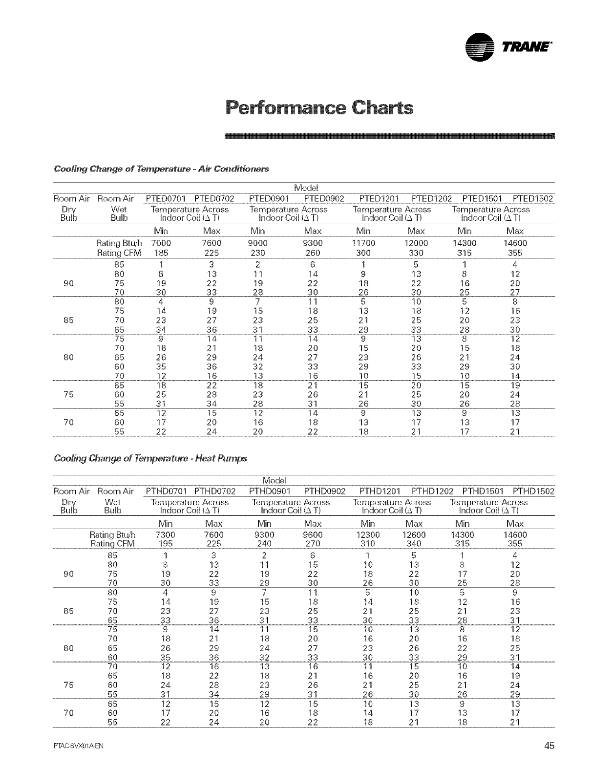
lri! liH£ °
Pe ot ance Charts
Cooling Change of Temperatu,.e oA_ Condi*ione_
Model
RoomAir RoomAir PTED0701 PTED0702 PTED0901 PTED0902 PTED1201 PTED1202 PTED1501 PTED1502
Dry W_ Temperature Across Temperature Across Temperature Across Temperature Across
Bulb Bulb indoor Coil (£ T} indoor Coil (£ T} indoor Coil (_ T} indoor Coil (_ T}
Min Max Min Max Min Max Min Max
Rating_u/h 7000 7600 9000 9300 11700 12000 14300 14600
Rating CFM 185 225 230 260 300 330 315 355
85 1 32 6 1 5 1 4
80 8 13 11 14 9 13 8 12
90 75 19 22 19 22 18 22 16 20
70 30 33 28 30 26 30 25 27
80 4 9 7 11 6 10 5 8
75 14 19 15 18 13 18 12 16
85 70 23 27 23 25 21 25 20 23
65 34 36 31 33 29 33 28 30
75 9 14 11 14 9 13 8 12
70 18 21 18 20 15 20 15 18
80 65 26 29 24 27 23 26 21 24
60 35 36 32 33 29 33 29 30
70 12 16 13 16 10 15 10 14
65 18 22 18 21 15 20 15 19
75 60 25 28 23 26 21 25 20 24
55 31 34 28 31 26 30 26 28
65 12 15 12 14 9 13 9 13
70 60 17 20 16 18 13 17 13 17
55 22 24 20 22 18 21 17 21
Cooling Change of Temperature - Heat Pumps
Model
RoomAir RoomAir PTHD0701 PTHD0702 PTHD0901 PTHD0902 PTHD1201 PTHD1202 PTHD1501 PTHD1502
Dry Wet Temperature Across Temperature Across
BuD Bulb indoor Coil (£ T} indoor Coil (£ T}
Min Max Min Max Min Max Min Max
Rating Btdh 7300 7600 9300 9600 12300 12600 14300 14600
Rating CFM 195 225 240 270 310 340 315 355
85 1 3 2 6 1 5 1 4
80 8 13 11 15 10 13 8 12
90 75 19 22 19 22 18 22 17 20
70 30 33 29 30 26 30 25 28
80 4 9 7 11 5 10 5 9
75 14 19 15 18 14 18 12 16
85 70 23 27 23 25 21 25 21 23
65 33 36 31 33 30 33 28 31
75 9 14 11 15 10 13 8 12
70 18 21 18 20 16 20 16 18
80 65 26 29 24 27 23 26 22 25
60 35 36 32 33 30 33 29 31
70 12 16 13 16 11 15 10 14
65 18 22 18 21 16 20 16 19
75 60 24 28 23 26 21 25 21 24
55 31 34 29 31 26 30 26 29
65 12 15 12 15 10 13 9 13
70 60 17 20 16 18 14 17 13 17
55 22 24 20 22 18 21 18 21
FTAC SVX01AEN 45
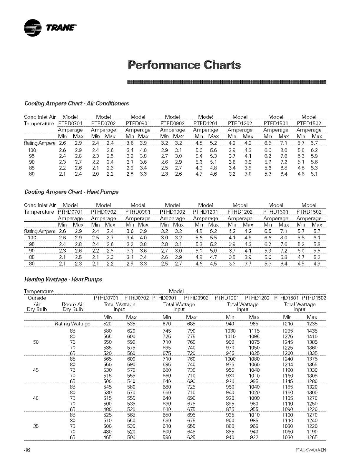
lrJ lN£ °
Pe :or ance Charts
Cooling Ampere Chart - Air Conditioners
Cond HnHetAir ModeH ModeH ModeH ModeH ModeH ModeH
Temperature PTED0701 PTED0702 PTED0901 PTED0902 PTED1201 PTED1202
Amperage Amperage Amperage Amperage Amperage Amperage
Min Max Min Max Min Max
RatingAmpere 2,6 2.9 2,4 2,4 3,6 3.9
100 2.6 2.9 2,4 2.6 &4 4.0
95 2,4 2.8 2.3 2.5 3.2 3.8
90 2.3 2.7 2.2 2.4 3.1 3.6
85 2,2 2.6 2.1 2,3 2,9 3.4
80 Z1 2.4 2.0 Z2 2.8 3.3
ModeH ModeH
PTED1501 PTED1502
Amperage Amperage
Min Max Min Max Min Max Min Max Min Max
3.2 3.2 4.8 5,2 4,2 4.2 6.5 7.1 5,7 5.7
2.9 3.1 5.6 5.6 3,9 4.3 6.6 &0 5.6 6.2
2.7 3.0 5.4 5.3 3,7 4.1 6.2 7.6 5.3 5,9
2,6 2,9 5,2 5.1 3.6 3,9 5,9 7,2 5.1 5,6
2,5 2,7 4.9 4.8 3.4 3,8 5,6 6.8 4,8 5.3
2.3 2.6 4.7 4.6 3.2 3.6 5.3 6.4 4`6 5.1
Cooling Ampere Chart - Heat Pumps
Cond Inlet Air ModeH ModeH ModeH ModeH ModeH ModeH ModeH ModeH
Temperature PTHD0701 PTHD0702 PTHD0901 PTHD0902 PTHD1201 PTHD1202 PTHD1501 PTHD1502
Amperage Amperage Amperage Amperage Amperage Amperage Amperage Amperage
Min Max Min Max Min Max Min Max Min Max Min Max Min Max Min Max
RatingAmpere 2.6 2,9 2.4 2.4 3,6 3,9 3,2 3,2 4,8 5,2 4,2 4`2 6,5 7,1 5,7 5.7
100 2,6 2,9 2.5 2.7 3,4 4`0 3,0 3,2 5,6 5,5 4,1 4,5 6,6 &0 5,5 6,1
95 2,4 2,8 2,4 2.6 3,2 3,8 2,8 3,1 5,3 5,2 3,9 4,3 6,2 7,6 5.2 5,8
90 2.3 2,6 2,2 2,5 3.1 3,6 2,7 3,0 &0 5,0 3,7 4,1 5,9 7,2 5,0 5.5
85 2,1 2,5 2,1 2,3 3,1 3,4 2,6 2,9 4,8 4`7 3.5 3,9 5,6 6,8 4.7 5,2
80 2,1 2,3 2,1 2,2 2,9 3,3 2,5 2,7 4,6 4,5 3,3 3,7 5,3 6,4 4,5 4,9
Heating Wattage - Heat Pumps
Temperature ModeH
Outside PTHD0701 PTHD0702 PTHD0901 PTHD0902 PTHD1201 PTHD1202 PTHD1501 PTHD1502
Air Room Air Total Wattage Total Wattage Total Wattage Total Wattage
Dry BuHb Dry BuHb Hnput Hnput Hnput Hnput
Min Max Min Max Min Max Min Max
Rating Wattage 520 535 670 685 940 965 1210 1235
85 580 620 745 790 1030 1115 1295 14.35
80 565 600 725 775 1010 1095 1275 1410
50 75 550 590 710 760 990 1075 1245 1385
70 535 575 695 740 970 1050 1225 1360
65 520 560 675 720 945 1025 1200 1335
85 565 600 710 760 1000 1080 1240 1375
80 550 590 695 740 975 1060 1214 1355
45 75 630 570 680 730 955 1040 1190 1330
70 515 555 660 710 930 1010 1160 1305
65 500 540 640 690 910 995 1145 1280
85 545 580 680 725 950 1040 1185 1320
80 530 570 660 710 940 1020 1160 1300
40 75 515 555 640 690 920 1000 1135 1270
70 500 535 630 675 895 980 1110 1250
65 480 520 610 675 875 955 1090 1220
85 525 565 650 695 925 1010 1130 1270
80 510 550 630 675 900 985 1110 1240
35 75 500 535 610 655 880 965 1080 1220
70 480 520 600 645 855 940 1060 1190
65 465 500 580 625 940 922 1030 1265
46 F]-AC SVX01AEN
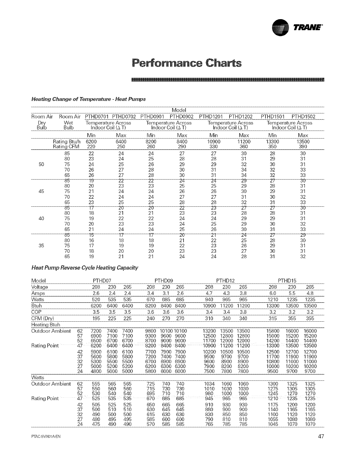
TI!i iH£ °
Pe or ance Charts
H_ting Change of Temperature oHeat Pumps
ModeH
Room Air Room Air PTHD0701 PTHD0702 PTHD0901 PTHD0902 PTHD1201 PTHD1202 PTHD1501 PTHD1502
5O
45
4O
35
Wet
Bulb
Min Max Min Max Min Max Min Max
Rating Btu/h 6200 6400 8200 8400 10900 11200 13300 13500
Rating CFM 220 250 260 290 330 360 350 990
85 22 24 24 27 27 30 28 30
80 23 24 25 28 28 31 29 31
75 24 25 26 29 29 32 30 31
70 26 27 28 30 31 34 32 33
65 26 27 28 30 31 34 32 33
_ _ 2-4 _4 29 27 30
80 20 23 23 25 25 29 28 31
75 21 24 24 26 26 30 29 31
70 22 24 24 27 27 31 30 32
65 23 25 25 28 28 32 31 33
20 20 _ 23- 27 27 30
80 18 21 21 23 23 28 28 31
75 19 22 22 24 24 29 29 31
70 20 23 23 24 25 29 30 32
65 21 24 24 25 26 30 31 33
85 15 r 17 20 21 Z4 2? 29
80 16 18 18 21 22 25 28 30
75 17 19 19 22 23 26 29 31
70 18 20 20 23 23 27 30 31
65 19 21 21 24 24 28 31 32
Heat Pump Reverse Cycle Heating Capacity
ModeH
VoHtage
Am ps
VVatts
Btuh
COP
CFM (Dry)
Heating Btuh
PTHD07 PTHD09 PTHD12 PTHD15
208 230 265 208 230 265 208 230 265 208 230 265
2=6 2_4 2_4 3,4 &l 2=6 4=7 4_3 &8 &0 &5 4=8
520 535 535 670 685 685 940 965 965 1210 1235 1235
6200 6400 6400 8200 6400 8400 10900 11200 11200 13300 13500 13500
3,5 3=5 3,5 3,6 3=6 3,6 3,4 3,4 3,8 3,2 3,2 3,2
195 225 225 240 270 270 310 340 340 315 355 355
OutdoorAmbient 62 7200 7400 7400 9800 1010010100 13200 13500 13500 15800 16000 16000
57 6900 7100 7100 9300 9600 9600 12500 12800 12800 15000 15200 15200
52 6500 6700 6700 8700 9000 9000 11700 12000 12000 14200 14400 14400
Rating Point 47 6200 6400 6400 8200 6400 8400 10900 11200 11200 1330013500 13500
42 5900 6100 6100
37 5600 5800 5800
32 5300 5500 5500
27 5000 5200 5200
24 4800 5000 5000
Wa_s
OutdoorAmbient 62 555 565 565
57 550 560 560
52 530 540 540
7700 7900 7900
7200 7400 7400
6700 6900 6900
6200 6300 6300
5800 6000 6000
10200 10500 10500
9500 9700 9700
9600 8900 8900
7900 8200 8200
7500 7800 7800
12500 12700 12700
11700 11900 11900
10800 11000 11000
10000 10200 10200
9500 9700 9700
725 740 740
715 730 730
695 710 710
1034 1060 1060
1010 1030 1030
980 1000 1000
1300 1325 1325
1275 1905 1305
1245 1270 1270
Rating Point 47 525 535 535 670 685 685 945 965 965 12101235 1235
42 505 525 525 650 665 665 910 930 930 1175 1200 1200
37 500 510 510 630 645 645 880 900 900 1140 1165 1165
32 490 500 500 615 630 630 830 850 850 1100 1120 1120
27 480 495 495 585 600 600 790 810 810 1055 1080 1080
24 475 490 490 570 585 585 765 785 785 1045 1070 1070
PTAC SVX01_EN 47
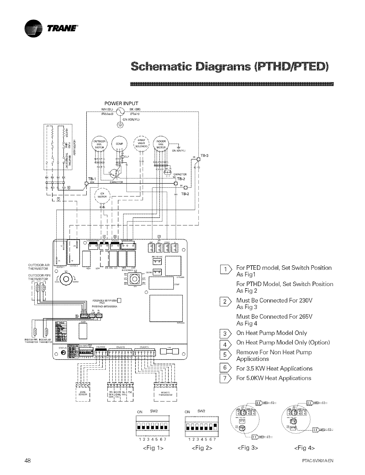
lti lN£ °
Schematic Diagrams (PTHD : ED)
POWER INPUT
WH (BLI ,_ BK (BR)
(Ribbed) _
N (GN/YL)
TB-3
mmm_
OUTDOOR AIR
THERMISTOR
OUTDOOR PIPE
THERM,_TOR
mE_MBSTORT_E_MBSTOF
_SSEMBLY_1A1_4 D
???£????
ON SW2 ON SW2
[_ For PTED modeU,Set Switch Position
As Fig1
For PTHD ModeU, Set Switch Position
As Fig 2
[_ Must Be Connected For 230V
As Fig 3
Must Be Connected For 265V
As Fig 4
[_ On Heat Pump ModeUOnUy
[_ On Heat Pump ModeUOnUy(Option)
[_ Remove For Non Heat Pump
AppUications
For 3.5 KW Heat AppUications
[_ For 5.0KWHeat Applications
48
1234567 1234567
<Fig 1> <Fig 2> <Fig 3> <Fig 4>
FFAC SVX01AEN
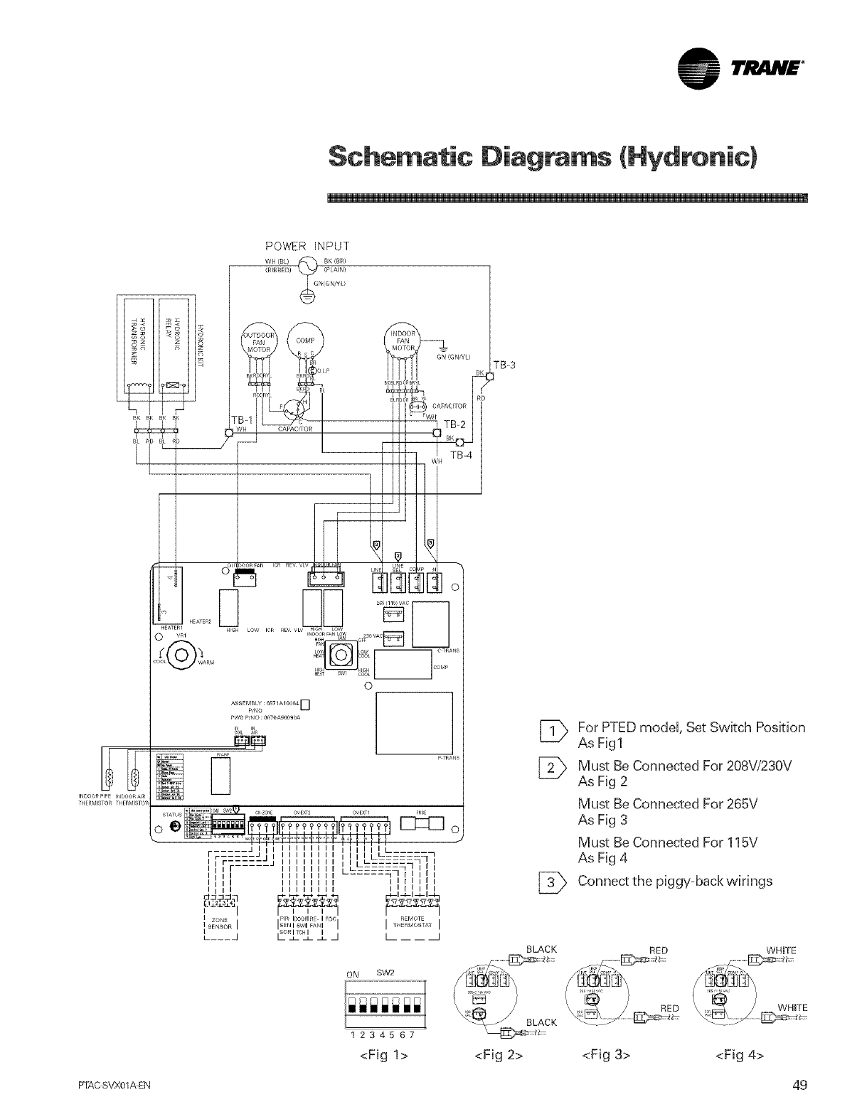
lrl_liH£ °
Schematic Diagrams (HVdronic)
POWER INPUT
WH {BL) _ BK !SR}
(_tIBBED) _
N(GNHL/
INDOORPIPE INDOOR_1_
THERMISTOR
PW_ P/NO :6870Ag0090A
% ,N
Q_ P 7RANS
ON SW2
1234567
TB-3
[_ For PTED model, Set Switch Position
As Fig1
[_ Must Be Connected For 208V/230V
As Fig 2
Must Be Connected For 265V
As Fig 3
Must Be Connected For 115V
As Fig 4
Connect the piggy=back wirings
BLACK RED
<Fig 1> <Fig 2> <Fig 3> <Fig 4>
WHITE
WHITE
FTAC SVX01AEN 49
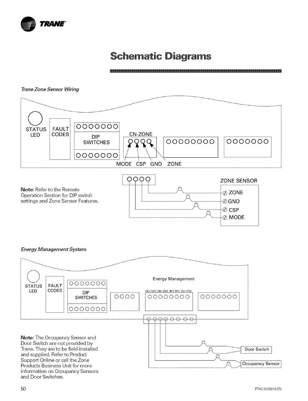
lrJ_lN£ °
Schematic Diagrams
Trane Zone Sensor Wiring
O--
STATUS FAULT
LED CODES
/
/
/
OOOOOOO
DIP
SWITCHES
OOOOOOO
MODE
Note: Refer to the Remote
Operation Section for DiP switch
settings and Zone Sensor Features.
CN-ZONE !°°°°°°°°
CSP GND ZONE
OOOOOOO
ZONE SENSOR
iL
iX_
@ ZONE
®GND
® CSP
4Z) MODE
Energy Management System
(_ _ ooooooo
STATUS
LED DIP
SWITCHES
0000000
/
/
0000
Note: The Occupancy Sensor and
Door Switch are not provided by
Trane. They are to be field-installed
and supplbd, Refer to Product
Support Online or call the Zone
Products Business Unit for more
information on Occupancy Sensors
and Door Switches,
Energy Management
OC1 OC2 DR1 DR2 RF1 RF2 FD1 FD2
00000000 0000000
(
_o _oo oo I OoorSw'tchl
_ Occupancy Sensor I
50 FFAC SVX01AEN
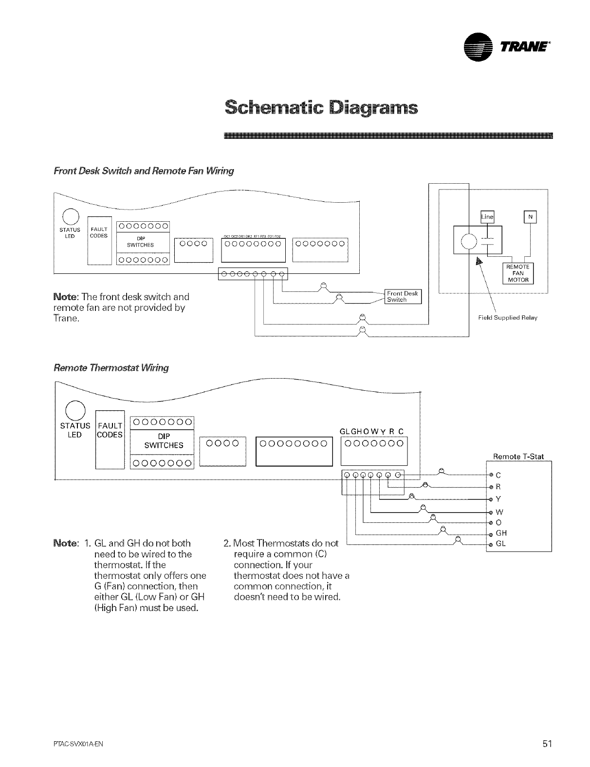
lri!iliH£ °
Schematic Diagrams
Front Desk Switch and Remote Fan Wiring
OOOOOO0
DIP
SWITCHES
0000000
J
Note: The front desk swkch and
remote fan are not provided by
Trane.
ocl oc2 _1 _2 RF1_2 _D1_UZ
00000000 0000000
I°°°°°i' A
Remote Thermostat Wiring
0 oooooo
STATUS
LED | DIP
SWITCHES O OOO
IOOOOOOO 00000000
Note: 1. GL and GH do not both
need to be wired to the
thermostat, ffthe
thermostat onUyoffers one
G (Fan} connection, then
either GL (Low Fan) or GH
(High Fan) must be used.
2. Most Thermostats do not
require a common (C)
connection, if your
thermostat does not have a
common connection, it
doesn't need to be wired.
GLGHOWY R C
OOOOOOO
Remote T-Stat
-eC
oR
_Y
8W
_0
-¢ GH
_e GL
PTAC SVX01AEN 5 1
°
Tra_
An American Standard Gompany
WW_ _a_COBF_
For more information contact
your local district office or
e mail us at comfort_trane, com
Literature Order Number PTAC-SVX01A-EN
File Number SV XN PTAC-000-SVX01A 0902 EN
Supersedes PTAC SVN01A-EN and PTAC SVU01A-EN
Stocking Location La Crosse
Trane has apolicy of continuous product and product dat_ improw, ment and reserves the right to change design
and specifications without notice, Only qualified technicians should perform the installation and servicing of
equipment referred to in d_ispublication,
