TRANE Air Conditioner/heat Pump(outside Unit) Manual L0801741
User Manual: TRANE TRANE Air conditioner/heat pump(outside unit) Manual TRANE Air conditioner/heat pump(outside unit) Owner's Manual, TRANE Air conditioner/heat pump(outside unit) installation guides
Open the PDF directly: View PDF ![]() .
.
Page Count: 8
TIMN£
It's Hard To Stop A Trane?
INSTALLER'S
G
TTP-IN-1D
18-AC34D1-5
Library Service Literature
Product Section Unitary
Product Split System Cooling
Model TTP
Literature Type Installer's Guide
Sequence 1D
Date June 2000
File No. SV-UN-S/S-TTP-IN-1D 6/00
Supersedes TTP-IN-1C
Model:
TTP018-024C, TTP030-O48D &TTPO60E Condensing Units
IMPORTANT -- This Document is customer property and is to remain with this unit. Please return to service information pack
upon completion of work.
These instructions do not cover all variations in systems
nor provide for every possible contingency to be met in
connection with installation. All phases of this installa-
tion must comply with NATIONAL, STATE AND LOCAL
CODES. Should further information be desired or should
particular problems arise which are not covered sufficiently fbr
the purchaser's purposes, the matter should be referred to your
installing deal or local distributor.
GENERAL
The following instructions cover TTP018-024C, TTP030-048D &
TTP060E Condensing Units.
NOTICE: These outdoor units may be used with indoor
units equipped with Capillary Tube, Thermostatic Ex-
pansion Valve or the Accutron TM Flow Control Check
Valve (F.C.C.V.) assembly for refrigerant flow control.
Check fbr transportation damage after unit is uncrated. Report
promptly, to the carrier, any damage found to the unit.
To determine the electrical power requirements of the unit, refer
to the nameplate of the unit. The electrical power available nmst
agree with that listed on the nameplate.
B. LOCATION & PREPARATION OF THE UNIT
1. The unit should be set on alevel support pad at least as large
as the unit base pan.
2. The support pad must NOT be in direct contact with any
structure. Unit nmst be positioned a minimmn of 12" from any
wall or su rrou nding shrubbery to insure adequ ate airflow. Clear-
ance must be provided in f_ont of control box (access panels) &
any other side requiring service access to meet National Electri-
cal Code. Also, the unit location must be far enough away fi'om
any structure to prevent excess roofrun-offwater from pouring
directly on the unit.
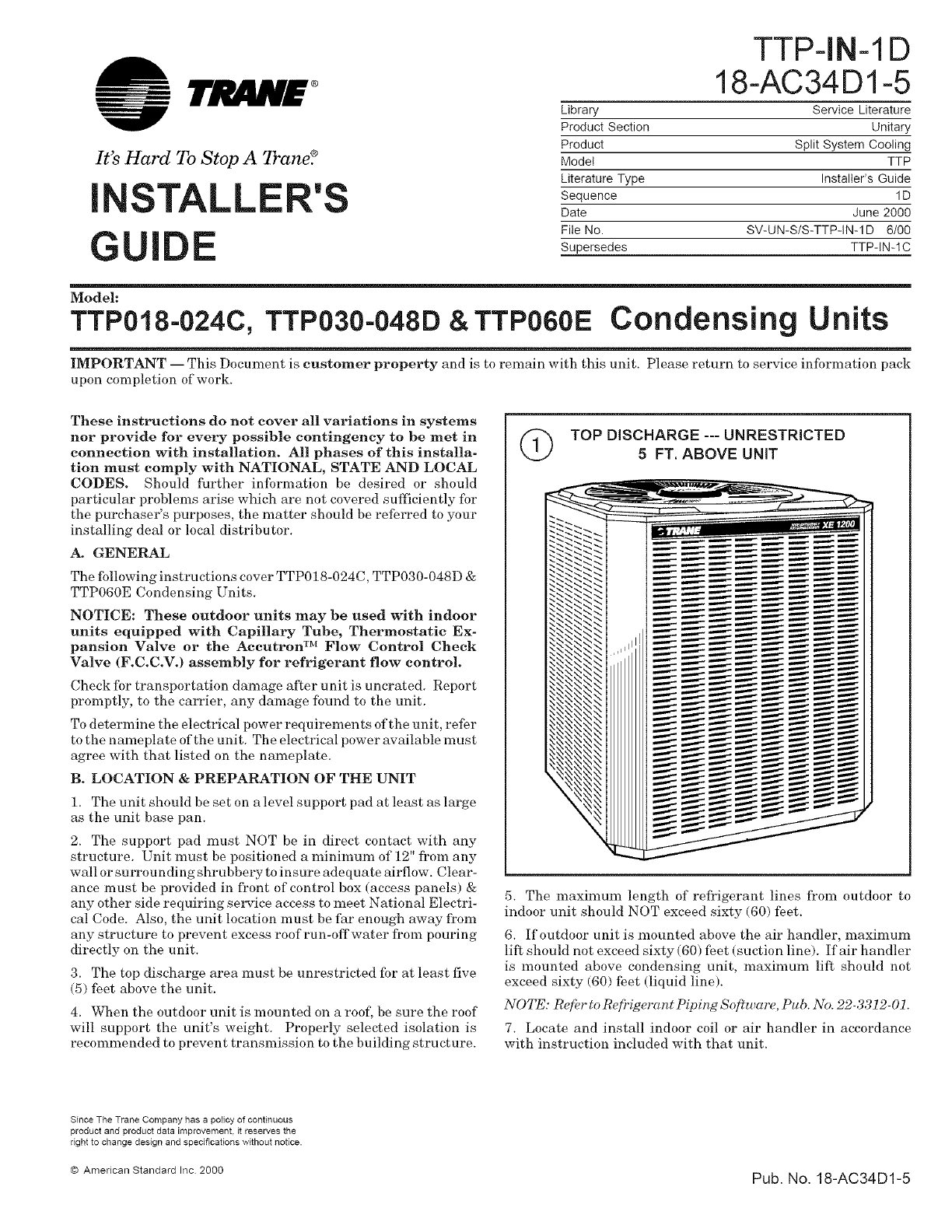
3. The top discharge area must be unrestricted fbr at least five
(5) feet above the unit.
4. When the outdoor unit is mounted on a roof, be sure the roof
will support the unit's weight. Properly selected isolation is
recommended to prevent transmission to the building structure.
(_ TOP DISCHARGE--- UNRESTRICTED
5FT. ABOVE UNIT
5. The maximum length of refrigerant lines fi'om outdoor to
indoor unit should NOT exceed sixty (60) feet.
6. If outdoor unit is mounted above the air handler, maximum
lift should not exceed sixty (60) fbet (suction line). If air handler
is mounted above condensing unit, maximum lift should not
exceed sixty (60) feet (liquid line).
NOTE: Refer to R@'igerant Piping Software, Pub. No. 22-3312-01.
7. Locate and install indoor coil or air handler in accordance
with instruction included with that unit.
Since The Trane Company has a policy of continuous
product and product data improvement, it reserves the
right to change design and specifications without notice.
© American Standard Inc 2000 Pub. No. 18-AC34D1-5
I STALLER'S GUIDE
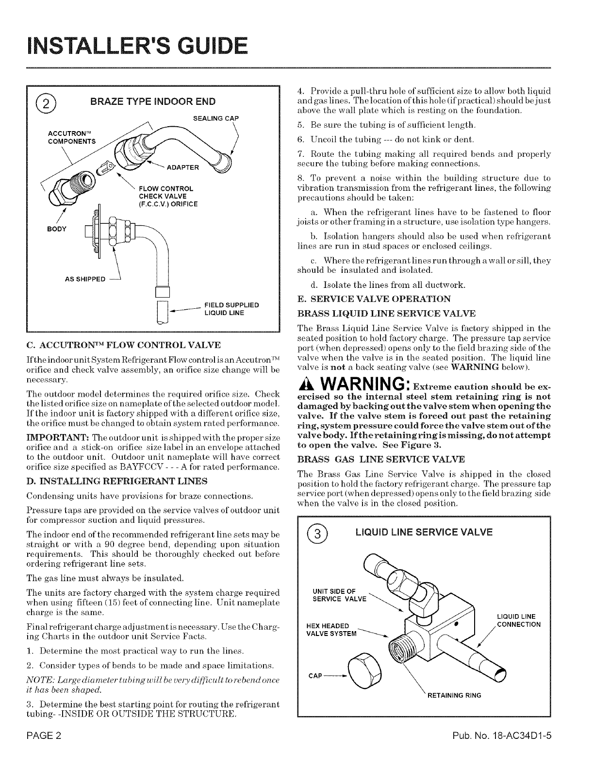
@BRAZE TYPE iNDOOR END
SEALING CAP
ACCUTRON TM
COMPONENTS
/
BODY
_'_ FLOW CONTROL
CHECK VALVE
(F.C.C.V.) ORIFICE
AS SHIPPED -_
FIELD SUPPLIED
LIQUID LINE
C. ACCUTRON TM FLOW CONTROL VALVE
c_ IM
If the indoor unit Syste In Refi'i_ erant F1ow control is an Accu tron-
orifice and check valve assembly, an orifice size change will be
necessary.
The outdoor model determines the required orifice size. Check
the listed orifice size on nameplate of the selected outdoor model.
If the indoor u nit is factory shipped with a dilIbrent orifice size,
the orifice must be changed to obtain system rated performance.
IMPORTANT: The outdoor u nit is shipped with the proper size
orifice and a stick-on orifice size label in an envelope attached
to the outdoor unit. Outdoor unit nameplate will have correct
orifice size specified as BAYFCCV - - - A fbr rated performance.
D. INSTALLING REFRIGERANT LINES
Condensing units have provisions for braze connections.
Pressure taps are provided on the service valves of outdoor unit
fbr compressor suction and liquid pressures.
The indoor end of the recommended refrigerant line sets may be
straight or with a 90 degree bend, depending upon situation
requirements. This should be thoroughly checked out before
ordering refl'igerant line sets.
The gas line must always be insulated.
The units are factory charged with the system charge required
when using fif_een (15) feet of connecting line. Unit nameplate
charge is the same.
Final refrigerant charge adjustment is necessary. Use the Charg-
ing (?harts in the outdoor unit Service Facts.
1. Determine the most practical way to run the lines.
2. Consider types of bends to be made and space limitations.
NOTE: Large diameter tubing will be very di[f_cult to rebend once
it has been shaped.
3. Determine the best starting point fbr routing the refl_igerant
tubing- -INSIDE OR OUTSIDE THE STRUCTURE.
4. Provide a pull-thru hole of suflicient size to allow both liquid
and gas lines. The location of this hole (if practical) should be just
above the wall plate which is resting on the foundation.
5. Be sure the tubing is of sufficient length.
6. Uncoil the tubing --- do not kink or dent.
7. Route the tubing maMng all required bends and properly
secure the tubing before making connections.
8. To prevent a noise within the building structure due to
vibration transmission fl_oln the refrigerant lines, the following
precautions should be taken:
a. When the refl'igerant lines have to be fastened to floor
joists or other fl'aming in a structure, use isolation type hangers.
b. Isolation hangers should also be used when refrigerant
lines are run in stud spaces or enclosed ceilings.
c. Where the refrigerant lines ru n through a wall or sill, they
should be insulated and isolated.
d. Isolate the lines fl'om all ductwork.
E. SERVICE VALVE OPERATION
BRASS LIQUID LINE SERVICE VALVE
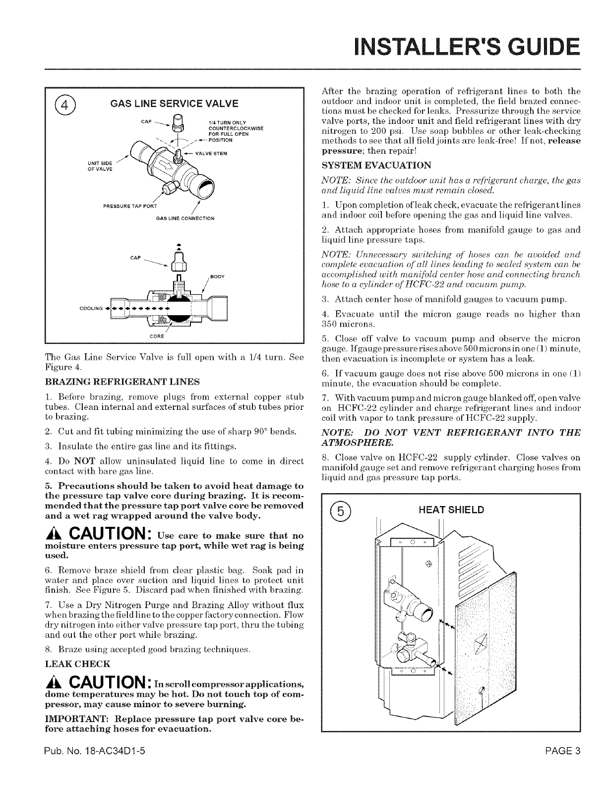
The Brass Liquid Line Service Valve is factory shipped in the
seated position to hold factory charge. The pressure tap service
port (when depressed) opens only to the field brazing side of the
valve when the valve is in the seated position. The liquid line
valve is not a back seating valve (see WARNING below).
WARNING: Extremecautionshouldbeex-
ercisedso the internal steel stem retaining ring is not
damaged by backing out the valve stem when opening the
valve. If the valve stem is forced out past the retaining
ring, system pressure could force the valve stem out of the
valve body. If the retaining ring is missing, do not attempt
to open the valve. See Figure 3.
BRASS GAS LINE SERVICE VALVE
The Brass Gas Line Service Valve is shipped in the closed
position to hold the factory refl'igerant charge. The pressure tap
service port (when depressed) opens only to the field brazing side
when the valve is in the closed position.
LIQUID LiNE SERVICE VALVE
UNIT SIDE OF
SERVICE VALVE
HEX HEADED
CAP-----_
LIQUID LINE
CONNECTION
RING
PAGE 2 Pub. No. 18-AC34D1-5
INSTALLER'S GUIDE
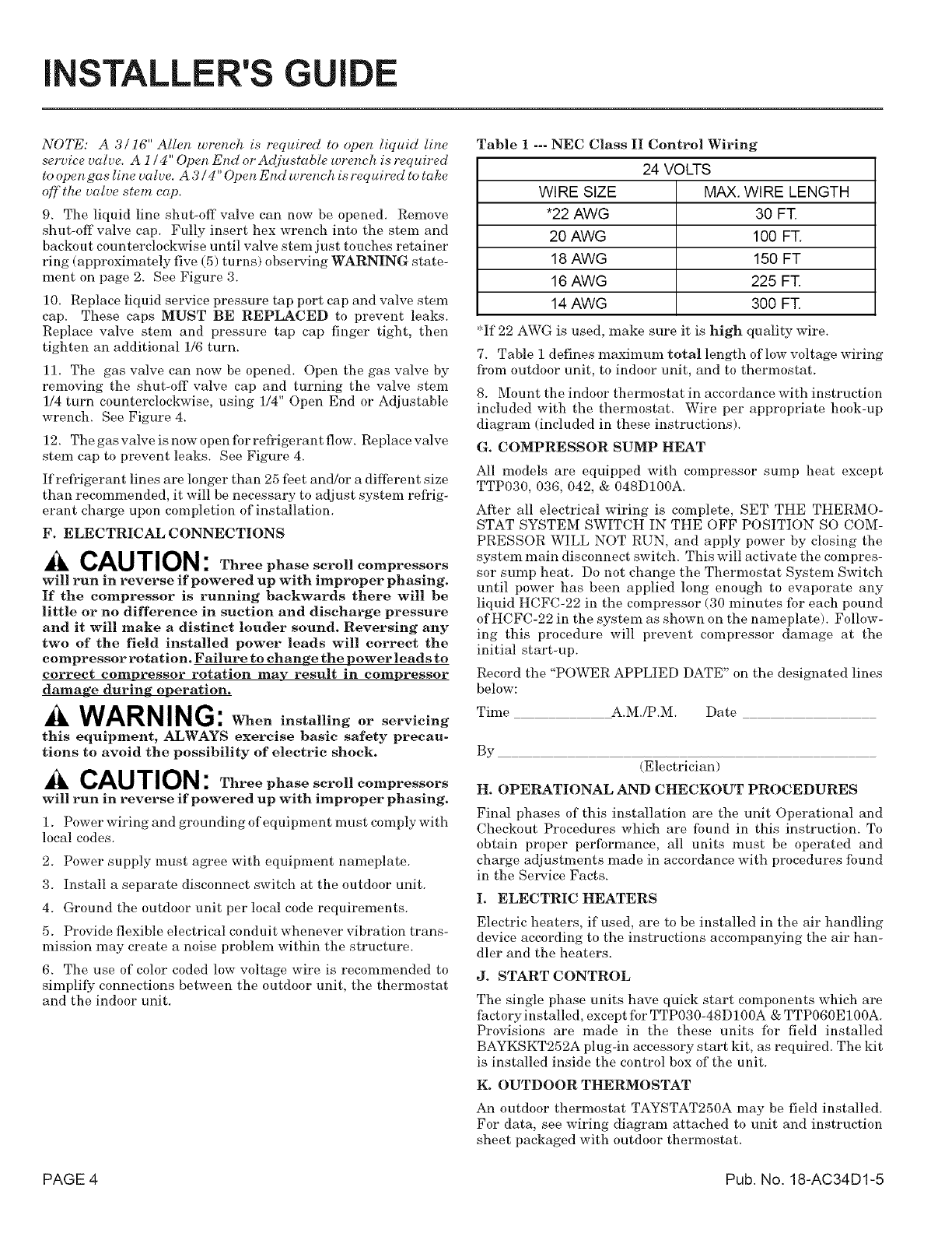
©GAS LINE SERVICE VALVE
CAP _ _ 1/4 TURN ONLY
COUNTERCLOCKWISE
UNIT SIDE
OF VALVE
#
PRESSURE TAP PORT j
/
GAS LINE CONNECTION
cAP_
CORE
The Gas Line Service Valve is full open with a 1/4 turn. See
Figure 4.
BRAZING REFRIGERANT LINES
1. Before brazing, remove plugs from external copper stub
tubes. Clean internal and external surfaces of stub tubes prior
to brazing.
2. Cut and fit tubing minimizing the use of sharp 90 ° bends.
3. Insulate the entire gas line and its fittings.
4. Do NOT allow uninsulated liquid line to come in direct
contact with bare gas line.
5. Precautions should be taken to avoid heat damage to
the pressure tap valve core during brazing. It is recom-
mended that the pressure tap port valve core he removed
and a wet rag wrapped around the valve body.
CAUTION: Use care to make sure that no
moisture enters pressure tap port, while wet rag is being
used.
6. Remove braze shield from clear plastic bag. Soak pad in
water and place over suction and liquid lines to protect unit
finish. See Figure 5. Discard pad when finished with brazing.
7. Use a Dry Nitrogen Purge and Brazing Alloy without flux
when brazing the field line to the copper factory connection. Flow
dry nitrogen into either valve pressure tap port, thru the tubing
and out the other port while brazing.
8. Braze using accepted good brazing techniques.
LEAK CHECK
CAUTION :In scrollcompressorapplications,
dome temperatures may be hot. Do not touch top of com-
pressor, may cause minor to severe burning.
IMPORTANT: Replace pressure tap port valve core be-
fore attaching hoses for evacuation.
After the brazing operation of refrigerant lines to both the
outdoor and indoor unit is completed, the field brazed connec-
tions must be checked fbr leaks. Pressurize through the service
valve ports, the indoor unit and field refl_igerant lines with dry
nitrogen to 200 psi. Use soap bubbles or other leak-checking
methods to see that all field joints are leak-fl'ee! If not, release
pressure; then repair!
SYSTEM EVACUATION
NOTE: Since the outdoor unit has a refrigerant charge, the gas
and liquid line valves must remain closed.
1. Upon colnpletion ofleak check, evacu ate the refrigerant lines
and indoor coil befbre opening the gas and liquid line valves.
2. Attach appropriate hoses froJn manififld gauge to gas and
liquid line pressure taps.
NOTE: Unnecessary switching of hoses can be avoided and
complete evacuation of'all lines leading to sealed system can be
accomplished with mani[bld center hose and connecting branch
hose to a qylinder of HCFC-22 and vacuum pump.
3. Attach center hose of manifbld gauges to vacuum pump.
4. Evacuate until the micron gauge reads no higher than
350 microns.
5. Close off valve to vacuum pump and observe the micron
gauge. Ifgaugepressurerisesabove 500micronsinone (1) minute,
then evacuation is incomplete or system has a leak.
6. If vacuum gauge does not rise above 500 microns in one (1)
minute, the evacuation should be complete.
7. With vacuum pump and micron gauge blanked off, open valve
on HCFC-22 cylinder and charge rel?igerant lines and indoor
coil with vapor to tank pressure of HCFC-22 supply.
NOTE: DO NOT VENT REFRIGERANT INTO THE
ATMOSPHERE.
8. Close valve on HCFC-22 supply cylinder. Close valves on
manifold gauge set and remove refrigerant charging hoses from
liquid and gas pressure tap ports.
HEAT SHIELD
Pub. No. 18-AC34D1-5 PAGE 3
I STALLER'S GUIDE
NOTE: A 3/16" Allen wrench is required to open liquid line
service valve. A 1/4" Open End or Adjustable wrench is required
to open gas line valve. A 3/4" Open End wrench is required to take
off the valve stem cap.
9. The liquid line shut-off valve can now be opened. Remove
shut-off valve cap. Fully insert hex wrench into the stein and
backout counterclockwise until valve stem just touches retainer
ring (approximately five (5) turns) observing WARNING state-
ment on page 2. See Figure 3.
10. Replace liquid service pressure tap port cap and valve stein
cap. These caps MUST BE REPLACED to prevent leaks.
Replace valve stem and pressure tap cap finger tight, then
tighten an additional 1/6 turn.
11. The gas valve can now be opened. Open the gas valve by
removing the shut-off valve cap and turning the valve stem
1/4 turn counterclockwise, using 1/4" Open End or Adjustable
wrench. See Figure 4.
12. The gas valve is now open fbr refrigerant flow. Replace valve
stem cap to prevent leaks. See Figure 4.
If refrigerant lines are longer than 25 feet and/or a different size
than recommended, it will be necessary to adjust system refrig-
erant charge upon completion of installation.
F. ELECTRICAL CONNECTIONS
CAUTION : Threephasescrollcompressors
will run in reverse if powered up with improper phasing.
If the compressor is running backwards there will be
little or no difference in suction and discharge pressure
and it will make adistinct louder sound. Reversing any
two of the field installed power leads will correct the
compressor rotation. Failure to change the power leads to
correct compressor rotation may result in compressor
damage during operation.
AWARNING: When installing or servicing
this equipment, ALWAYS exercise basic safety precau-
tions to avoid the possibility of electric shock.
ACAUTION : Threephasescrollcompressors
will run in reverse if powered up with improper phasing.
1. Power wiring and grounding of equipment mu st comply with
local codes.
2. Power supply must agree with equipment nameplate.
3. Install a separate disconnect switch at the outdoor unit.
4. Ground the outdoor unit per local code requirements.
5. Provide flexible electrical conduit whenever vibration trans-
mission may create a noise problem within the structure.
6. The use of color coded low voltage wire is recommended to
simplify connections between the outdoor unit, the thermostat
and the indoor unit.
Table 1 --- NEC Class II Control Wiring
24 VOLTS
WIRE SIZE MAX. WIRE LENGTH
*22 AWG 30 FT.
20 AWG 100 FT.
18 AWG 150 FT
16 AWG 225 FT.
14 AWG 300 FT.
'_If 22 AWG is used, make sure it is high quality wire.
7. Table i defines maximum total length of low voltage wiring
from outdoor unit, to indoor unit, and to thermostat.
8. Mount the indoor thermostat in accordance with instruction
included with the thermostat. Wire per appropriate hook-up
diagram (included in these instructions).
G. COMPRESSOR SUMP HEAT
All models are equipped with compressor sump heat except
TTP030, 036, 042, & 048D100A.
Al_er all electrical wiring is complete, SET THE THERMO-
STAT SYSTEM SWITCH IN THE OFF POSITION SO COM-
PRESSOR WILL NOT RUN, and apply power by closing the
system main disconnect switch. This will activate the compres-
sor sump heat. Do not change the Themnostat System Switch
until power has been applied long enough to evaporate any
liquid HCFC-22 in the compressor (30 minutes for each pound
of HCFC-22 in the system as shown on the nameplate). Follow-
ing this procedure will prevent compressor damage at the
initial start-up.
Record the "POWER APPLIED DATE" on the designated lines
below:
Time A.M./P.M. Date
By
(Electrician)
H. OPERATIONAL AND CHECKOUTPROCEDURES
Final phases of this installation are the unit Operational and
Checkout Procedures which are found in this instruction. To
obtain proper perfbrmance, all units must be operated and
charge adjustments made in accordance with procedures found
in the Service Facts.
I. ELECTRIC HEATERS
Electric heaters, if used, are to be installed in the air handling
device according to the instructions accompanying the air han-
dler and the heaters.
J. STARTCONTROL
The single phase units have quick start components which are
factoryinstalled, except for TTP030-48D100A & TTP060E100A.
Provisions _'e made in the these units for field installed
BAYKSKT252A plug-in accessory start kit, as required. The kit
is installed inside the control box of the unit.
K. OUTDOORTHERMOSTAT
An outdoor thermostat TAYSTAT250A may be field installed.
For data, see wiring diagram attached to unit and instruction
sheet packaged with outdoor thermostat.
PAGE 4 Pub. No. 18-AC34D1-5
INSTALLER'S GUIDE
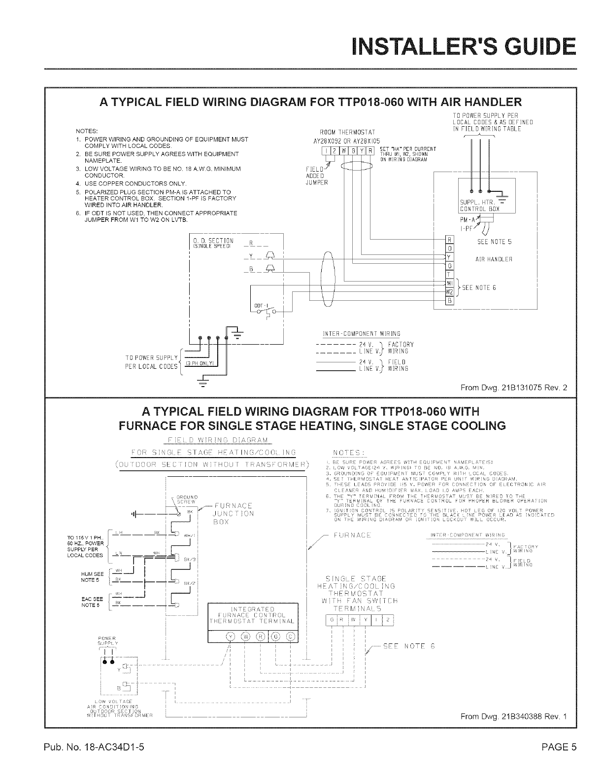
A TYPICAL FIELD WIRING DIAGRAM FOR TTP018-060 WiTH AiR HANDLER
NOTES:
1 POWER WIRING AND GROUNDING OF EQUIPMENT MUST
COMPLY WITH LOCAL CODES
2 BE SURE POWER SUPPLY AGREES WITH EQUIPMENT
NAMEPLATE.
3 LOW VOLTAGE WIRING TO BE NO. 18 A.WG MINIMUM
CONDUCTOR.
4 USE COPPER CONDUCTORS ONLY.
5 POLARIZED PLUG SECTION PM-A IS ATTACHED TO
HEATER CONTROL BOX SECTION 1-PF IS FACTORY
WIRED INTO AIR HANDLER.
6 IF ODT IS NOT USED, THEN CONNECT APPROPRIATE
JUMPER FROM Wl TO W2 ON LVTB.
O. O. SECTION
[SINGLESPEEO)
F[EL 11[_
ADDED
JUMPER
R1
,
i
_L
ROOM THERMOSTAT
AY28X092 OR AY28XI05
_[ SET"HA"PERCURRENT
THRU Wl, W2, SHOWN
ON WIRING DIAGRAM
J
INTER COMPONENT WIRING
24 V. _ FACTORY
....... LINE V_ WIRING
24 V. ] FIELD
LINE V_ WIRING
TO POWER SUPPLY PER
LOCAL COOES & AS DEFINED
IN FIELO WIRING TABLE
SEE NOTE 5
AIR HANDLER
NOTE6
From Dwg. 2IB131075 Rev. 2
A TYPICAL FIELD WIRING DIAGRAM FOR TTP018-060 WITH
FURNACE FOR SINGLE STAGE HEATING, SINGLE STAGE COOLING
F',/7 R C D DCR N,M
N "F OF: _ N{I E _1 A( qF/!,,T ]N(WCO0 I,_ NOIES :
(O_ DOOR EC iE)_ W HOJ I RAG ORblER} e SJRE PO/,'ER AGREES '¢ T OUIP!,/SNT ;\AM P DT S
2 10W '¢OI IAC! 24 ?7v/ ING} I O B NC S A'/,JG MiN
3 GTOUND'NG 0 EGO PqENl bUS COV'LY CH FLOCAL CODES
4 £E IHER!,,IOS A] HEA AN C PA O_ P R LJNI 'A_R G D AGRA,4
TJ SE t ADS PROV D 5 ', P0'/,ER FOR CONNECTION OF EkECTRON C AIR
CI EANER AND IUM 0 F E MAX iOAD I0 AMP EACl
6 H£ "Y" ERM NAL RUM T E THERMOS A 4USI BE WRED O
"v'" IERbI'NA O 1HE FU_ _CE {ON RO FO RO ER BL O'hER O_-RA ION
OUR NG COOk N8
7 Gq T ON CO'/TROL S POLDR T' SENST vHOT _EG OF 120 VO T POd_ERi
_I_ SUPPLy MUS BE CONNEC [} OIHE BLACK L NE POWER EA} aS DCAIE }
o I[ G'I /'\G 31A(_Ak/ (}R 0 I O {}C_((}L 'W[ OC{LR
TOl15V1 PH fl LI
60 HZ. POWER
SUPP_ PER
LOCALCODES L,' I
NOTE5 _ BK
GROt ND
/iJ < q ,!\(, E
+_ IiK I J N : ON
Bo×
EAC SEE [ '_'----J
NOTE5 / BK
, _E:7-]
I------':_ Bk/3 i
J
c-
I i TE OR A E D
.............................. F t:/W A( [ ( C N I P OL
/
lIE _OS'A lEIvl NAL
ILJI: p y
'fi .........! /' ,
........ _ L.......
........ i i
I '
i
I
LO_' /0i rACm I I
A]R CON[ I )N IN(
O:/T OO0q S CTION
','v I toJ 1?At , O_MIR
FURNACE
/
i
SINGE STAGE
itEATiNG/C 00 NO
ilLRMOSTAT
/v{ i AM, '-.WIT ( i
ERb' NAi _
IN ;EI COMPO'1I N I'/ih IN{)
............................................................ 24 ,' 1FAtTDRY
•NE ,/J W]R I G
24 [ FIEiD
"L NE J W]RI G
I
i'
i
1/ SEE NOTE f>
F
From Dwg. 2IB340388 Rev. I
Pub, No, 18-AC34D1-5 PAGE 5
I STALLER'S GUIDE
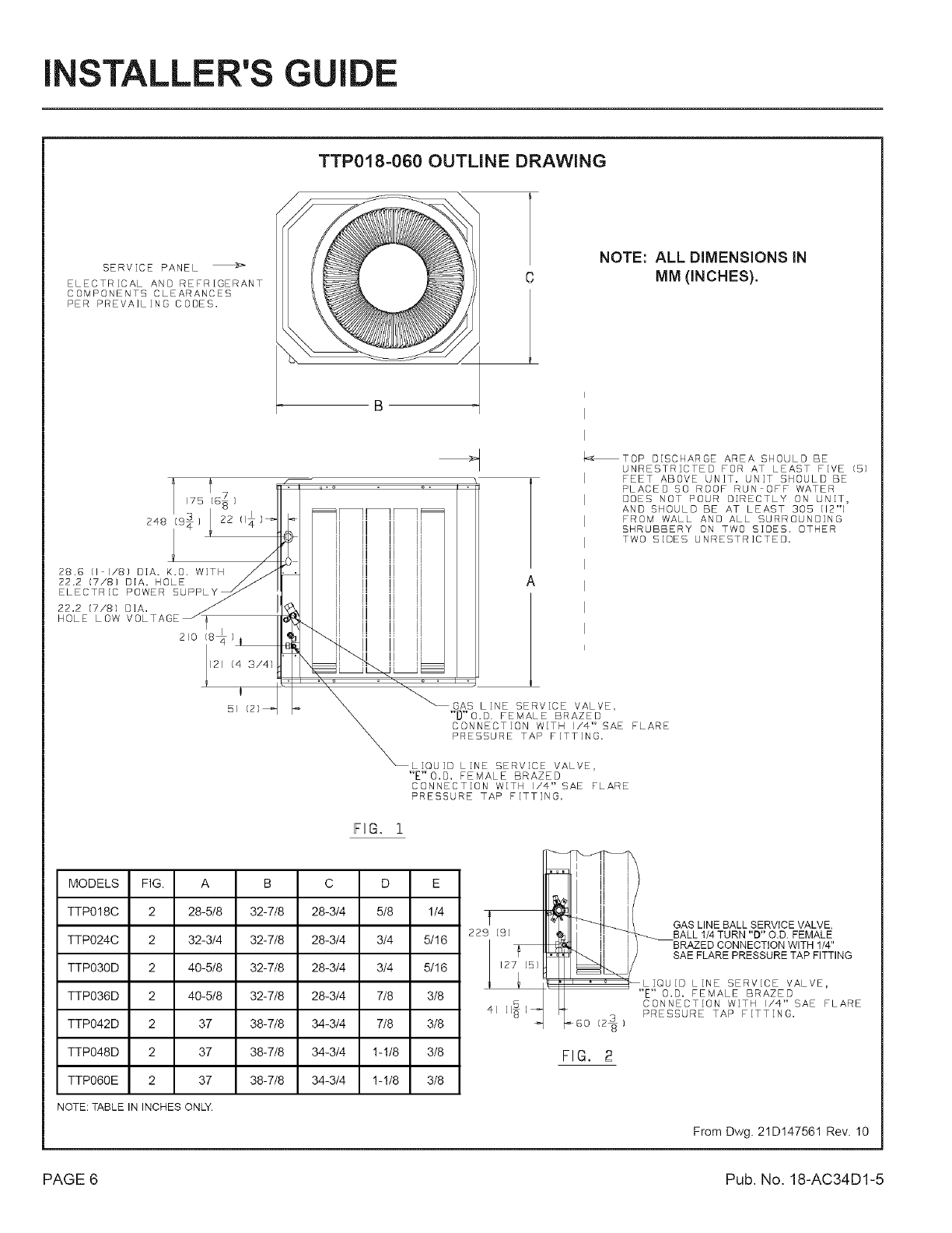
TTP018=060 OUTLINE DRAWING
SERVICE PANEL
ELECTRICAL AND REFRIGERANT
COMPONENTS CLEARANCES
PER PREVAiLiNG CODES.
22.2 (7/8) D]A. /
VOLTAGE J}
HOLE LOW 210 18_ )
yI21 14 3/4)
BI
NOTE: ALL DIMENSIONS IN
MM (INCHES).
_TOP DISCHARGE AREA SHOULD BE
UNRESTRICTED FOR AT LEAST FIVE (5)
FEET ABOVE UNIT. UNiT SHOULD BE
PLACED SO ROOF RUN OFF WATER
DOES NOT POUR DIRECTLY ON UNIT,
AND SHOULD BE AT LEAST 305 [12"1
FROM WALL AND ALL SURROUNDING
SHRUBBERY ON TWO SIDES. OTHER
TWO SIDES UNRESTRICTED.
A
GAB LiNE SERVICE VALVE,
"D"O.D. FEMALE BRAZED
CONNECTION WITH I/4" SAE FLARE
PRESSURE TAP FITTING.
LiQUiD LINE SERVICE VALVE,
"E'VO.D. FEMALE BRAZED
CONNECTION WITH I/4" SAE FLARE
PRESSURE TAP FITTING.
FIG. 1
MODELS FIG. A B C D E
TTPO18C 2 28-5/8 32-7/8 28-3/4 5/8 1/4
TTPO24C 2 32-3/4 32-7/8 28-3/4 3/4 5/16
TTPO30D 2 40-5t8 32-7/8 28-3/4 3/4 5/16
TTPO36D 2 40-5/8 32-7/8 28-3/4 7/8 3/8
TTPO42D 2 37 38-7/8 34-3/4 7/8 3/8
TTPO48D 2 37 38-7/8 34-3/4 !-!/8 3/8
TTPO60E 2 37 38-7/8 34-3/4 !-!/8 3/8
NOTE: TABLEIN INCHESONLY.
f
229 191
lq
kGo
FIG, 2
GAS LINE BALL SERVICE VALVE,
---._ BALL 1/4 TURN "D" O.D. FEMALE
BRAZED CONNECTION WITH 1/4"
SAE FLARE PRESSURE TAP FITTING
LIQUID LINE SERVICE VALVE,
"E" o.o. FEMALE BRAZED
CONNECTION WiTH I/4" SAE FLARE
PRESSURE TAP FITTING.
From Dwg. 21DI47561 Rev. I0
PAGE 6 Pub. No. 18-AC34D1-5
INSTALLER'S GUIDE
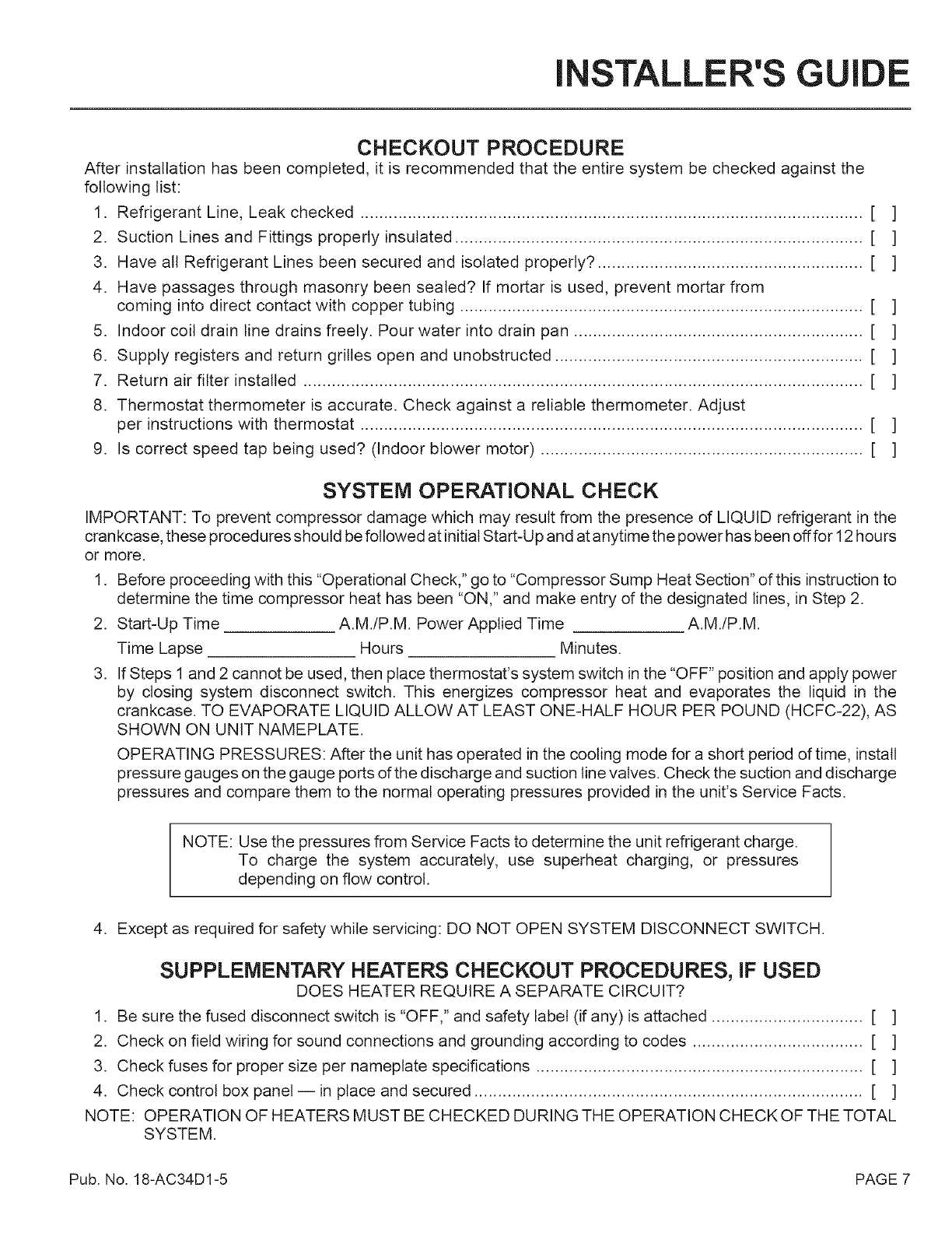
CHECKOUT PROCEDURE
After installation has been completed, it is recommended that the entire system be checked against the
following list:
1. Refrigerant Line, Leak checked .......................................................................................................... [ ]
2. Suction Lines and Fittings properly insulated ...................................................................................... [ ]
3. Have all Refrigerant Lines been secured and isolated properly? ........................................................ [ ]
4. Have passages through masonry been sealed? If mortar is used, prevent mortar from
coming into direct contact with copper tubing ..................................................................................... [ ]
5. Indoor coil drain line drains freely. Pour water into drain pan ............................................................. [ ]
6. Supply registers and return grilles open and unobstructed ................................................................. [ ]
7. Return air filter installed ...................................................................................................................... [ ]
8. Thermostat thermometer is accurate. Check against a reliable thermometer. Adjust
per instructions with thermostat .......................................................................................................... [ ]
9. Is correct speed tap being used? (Indoor blower motor) .................................................................... [ ]
SYSTEM OPERATIONAL CHECK
IMPORTANT: To prevent compressor damage which may result from the presence of LIQUID refrigerant in the
crankcase, these procedures should be followed at initial Start-Up and at anytime the power has been offfor 12 hours
or more.
1. Before proceeding with this "Operational Check," go to "Compressor Sump Heat Section" of this instruction to
determine the time compressor heat has been "ON," and make entry dthe designated lines, in Step 2.
2. Start-Up Time A.M./P.M. Power Applied Time A.M./P.M.
Time Lapse Hours Minutes.
3. If Steps 1 and 2 cannot be used, then place thermostat's system switch in the "OFF" position and apply power
by closing system disconnect switch. This energizes compressor heat and evaporates the liquid in the
crankcase. TO EVAPORATE LIQUID ALLOW AT LEAST ONE-HALF HOUR PER POUND (HCFC-22), AS
SHOWN ON UNIT NAMEPLATE.
OPERATING PRESSURES: After the unit has operated in the cooling mode for a short period of time, install
pressure gauges on the gauge ports of the discharge and suction line valves. Check the suction and discharge
pressures and compare them to the normal operating pressures provided in the unit's Service Facts.
NOTE: Use the pressures from Service Facts to determine the unit refrigerant charge.
To charge the system accurately, use superheat charging, or pressures
depending on flow control.
4. Except as required for safety while servicing: DO NOT OPEN SYSTEM DISCONNECT SWITCH.
SUPPLEMENTARY HEATERS CHECKOUT PROCEDURES, IF USED
DOES HEATER REQUIRE A SEPARATE CIRCUIT?
1. Be sure the fused disconnect switch is "OFF," and safety label (if any) is attached ................................ [ ]
2. Check on field wiring for sound connections and grounding according to codes .................................... [ ]
3. Check fuses for proper size per nameplate specifications ..................................................................... [ ]
4. Check control box panel -- in place and secured .................................................................................. [ ]
NOTE: OPERATION OF HEATERS MUST BE CHECKED DURING THE OPERATION CHECKOF THE TOTAL
SYSTEM.
Pub. No. 18-AC34D1-5 PAGE 7
I STALLER'S GUIDE
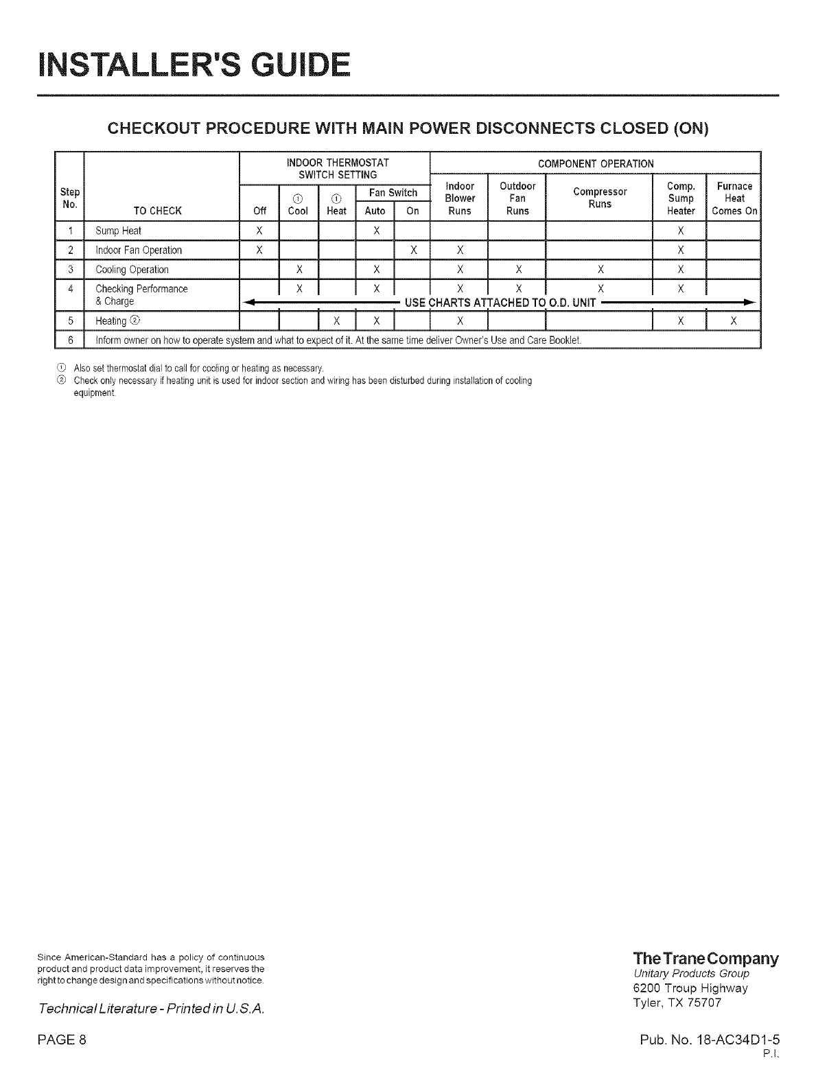
CHECKOUT PROCEDURE WITH MAiN POWER DISCONNECTS CLOSED (ON)
indoor
Step
No. TO CHECK
t Sump Heat
2 indoor Fan Operation
3 Cooling Operation
4 CheckingPerformance
& Charge
5 HeatingQ
6
iNDOORTHERMOSTAT
SWITCH SETTING
Q G Fan Switch
Off Cool Heat Auto On
X X
X X
X X
I x x
4
Blower
Runs
X
X
X
USE CHARTS ATTACHED TO O.D. UNIT
Ix N !
COMPONENTOPERATION
Outdoor
Fan Compressor
Runs
Runs
X X
I x x I
I
inform owner on how to operatesystem andwhat to expectof it. At the same time deliverOwner'sUseand Care Booklet.
Comp.
Sump
Heater
X
X
X
XI
N
Also set thermostat dial to call for cooling or heating as necessary.
@ Check only necessary if heating unit is used for indoor section and wiring has been disturbed during installation of cooling
equipment
Furnace
Heat
Comes On
P
X
Since American-Standard has a policy of continuous
product and product data improvement, it reserves the
right to change design and specifications without notice
Technical Literature -Printed in U.S.A.
TheTraneCompany
Unitary Products Group
6200 Troup Highway
Tyler, TX 75707
PAGE 8 Pub. No. 18-AC34D1-5
P.I.
