TRANE Furnace/Heater, Gas Manual L0902557
User Manual: TRANE TRANE Furnace/Heater, Gas Manual TRANE Furnace/Heater, Gas Owner's Manual, TRANE Furnace/Heater, Gas installation guides
Open the PDF directly: View PDF ![]() .
.
Page Count: 38
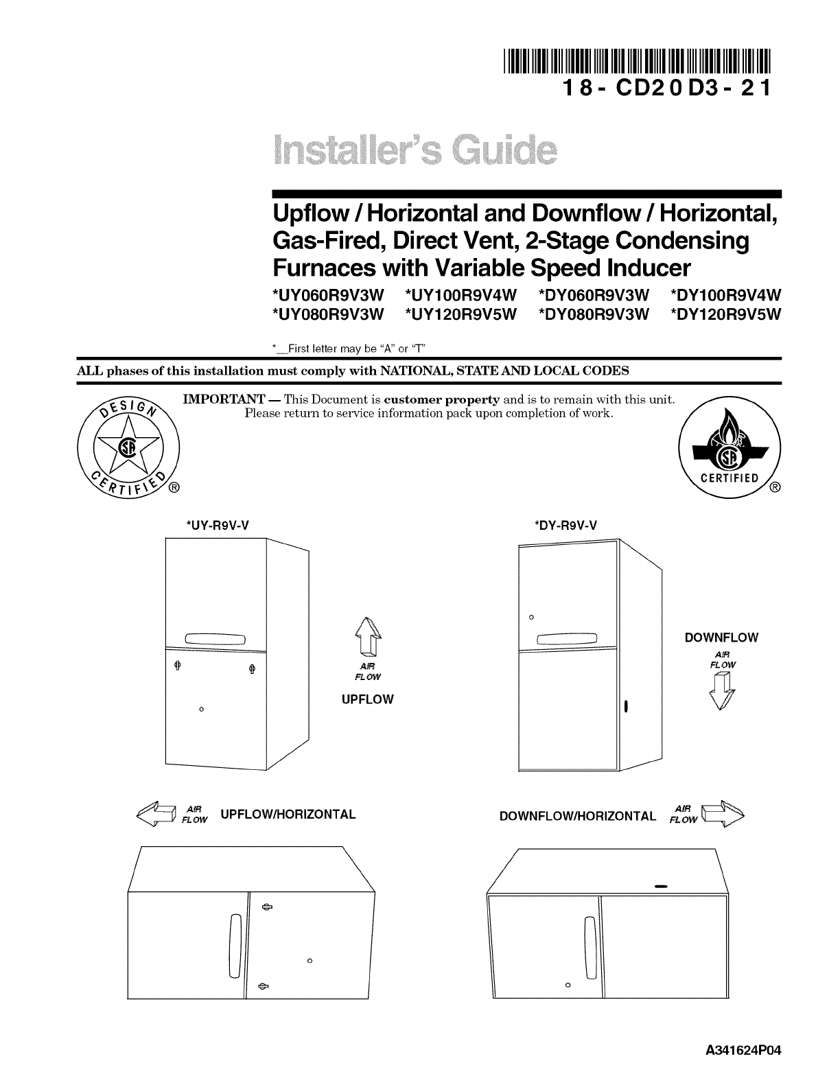
1 8 - CD2 0 D3 - 21
i_t'_"ii_ii,!i;"!i_i,_ii!:':iii! _ii,i_!:!:_,!il'¸'''__iIii_;
Upflow /Horizontal and Downflow /Horizontal,
Gas-Fired, Direct Vent, 2-Stage Condensing
Furnaces with Variable Speed Inducer
*UY060R9V3W *UY100R9V4W *DY060R9V3W *DY100R9V4W
*UY080R9V3W *UY120R9V5W *DY080R9V3W *DY120R9V5W
*__First letter may be "A" or 'q-"
ALL phases of this installation must comply with NATIONAL, STATE AND LOCAL CODES
IMPORTANT -- This Document is customer property and is to remain with this unit.
Please return to service information pack upon completion of work.
*UY-R9V-V *DY-R9V-V
(
AIR
FLOW
UPFLOW
DOWNFLOW
A_t
FLOW
AN UPFLOW/HORIZONTAL
FLOW
/\
DOWNFLOW/HORIZONTAL F_O_W_
/_ \
o
A341624P04
Installer's Guide
SAFETY SECTION
The following safety practices and precautions must be
followed during the installation, servicing, and operation of
this furnace.
1. Use only with the type of gas approved for this furnace.
Refer to the furnace rating plate.
2. Install this furnace only in a location and position as
specified in "Location and Clearances" (page 3), of these
instructions.
3. Provide adequate combustion and ventilation air to the
furnace space as specified in "Air for Combustion and
Ventilation" (page 7), of these instructions.
4. Combustion products must be discharged outdoors.
Connect this furnace to an approved vent system only, as
specified in the "Venting" section (pages 13-24), of these
instructions.
5. Never test for gas leaks with an open flame. Use a
commercially available soap solution made specifically
for the detection of leaks to check all connections, as
specified in "Gas Piping" (page 31), of these instructions.
6. Always install the furnace to operate within the furnace's
intended temperature-rise range with a duct system
which has an external static pressure within the allow-
able range, as specified on the unit rating plate. Airflow
with temperature rise for cfm versus static is shown in
the Service Facts accompanying this furnace.
7. When a furnace is installed so that supply ducts carry air
circulated by the furnace to areas outside the space
containing the furnace, the return air shall also be
handled by a duct(s) sealed to the furnace casing and
terminating outside the space containing the furnace.
8. A gas-fired furnace for installation in a residential
garage must be installed as specified in "Location and
Clearances" section (page 3), of these instructions.
9. The furnace may be used for temporary heating of
buildings or structures under construction only when the
following conditions have been met:
a. The furnace venting system must be complete and
installed per manufacturer's instructions.
b. The furnace is controlled only by a room thermostat
(no field jumpers).
c. The furnace return air duct must be complete and
sealed to the furnace and clean air filters are in place.
d. The furnace input rate and temperature rise must be
verified to be within nameplate marking.
e. 100% of the furnace combustion air requirement must
come from outside the structure.
f. The furnace return air temperature range is between
55 and 80 degrees Fahrenheit.
g. Clean the furnace, duct work, and components upon
substantial completion of the construction process,
and verify furnace operating conditions including
ignition, input rate, temperature rise and venting,
according to the manufacturer's instructions.
I10. TGhisslpirltdru_t thUStcboeja:pip:dbhYc_ Lh_aCsenascedPlet_!)erot1
Safety signal words are used to designate a degree or level
of seriousness associated with a particular hazard. The
signal words for safety markings are WARNING and
CAUTION.
a. WARNING indicates a potentially hazardous situation
which, if not avoided, could result in death or serious injury.
b. CAUTION indicates a potentially hazardous situation
which, if not avoided, may result in minor or moderate
injury. It is also used to alert against unsafe practices
and hazards involving only property damage.
CARBON MONOXIDE POISONING HAZARD
Failure to follow the steps outlined below for each
appliance connected to the venting system being
placed into operation could result in carbon monoxide
poisoning or death.
The following steps shall be followed for each appliance
connected to the venting system being placed into
operation, while all other appliances connected to the
venting system are not in operation:
1. Seal any unused openings in the venting system.
2. Inspect the venting system for proper size and
horizontal pitch, as required in the National Fuel Gas
Code, ANSI Z223.1/NFPA 54 or the CAN/CGA B149
Installation Codes and these instructions. Determine
that there is no blockage or restriction, leakage,
corrosion and other deficiencies which could cause an
unsafe condition.
3. As far as practical, close all building doors and
windows and all doors between the space in which the
appliance(s) connected to the venting system are
located and other deficiencies which could cause an
unsafe condition.
4. Close fireplace dampers.
5. Turn on clothes dryers and any appliance not
connected to the venting system. Turn on any exhaust
fans, such as range hoods and bathroom exhausts, so
they are operating at maximum speed. Do not operate
a summer exhaust fan.
6. Follow the lighting instructions. Place the appliance
being inspected into operation. Adjust the thermostat
so appliance is operating continuously.
7. If improper venting is observed during any of the above
tests, the venting system must be corrected in
accordance with the National Fuel Gas Code,
ANSI Z221.1/NFPA 54 and/or CAN/CGA B149
Installation Codes.
8. After it has been determined that each appliance
connected to the venting system properly vents where
tested as outlined above, return doors, windows,
exhaust fans, fireplace dampers and any other gas-fired
burning appliance to their previous conditions of use.
FIRE OR EXPLOSION HAZARD
Failure to follow the safety warnings exactly could result in
serious injury, death or property damage.
Improper servicing could result in dangerous operation,
serious injury, death, or property damage.
To prevent shortening its service life, the furnace should not
be used as a "Construction Heater" during the finishing
phases of construction until the requirements listed in item
9, a-g of the safety section of this publication have been met.
Condensate in the presence of chlorides and fluorides from
paint, varnish, stains, adhesives, cleaning compounds, and
cement create a corrosive condition which may cause rapid
deterioration of the heat exchanger.
© 2008 Trane All Rights Reserved 18-CD20D3-21
GENERAL INSTALLATION INSTRUCTIONS
The manufacturer assumes no responsibility for equipment
installed in violation of any code or regulation.
It is recommended that Manual J of the Air Conditioning
Contractors Association (ACCA) or A.R.I. 230 be followed in
estimating heating requirements. When estimating heating
requirements for installation at altitudes above 2000 ft.,
remember the gas input must be reduced (See GAS INPUT
ADJUSTMENT).
Material in this shipment has been inspected at the
factory and released to the transportation agency
without known damage. Inspect exterior of carton for
evidence of rough handling in shipment. Unpack
carefully after moving equipment to approximate
location. If damage to contents is found, report the
damage immediately to the delivering agency.
Codes and local utility requirements governing the installa-
tion of gas fired equipment, wiring, plumbing, and flue
connections must be adhered to. In the absence of local codes,
the installation must conform with latest edition of the
National Fuel Gas Code ANSI Z223.1 • National Installation
Code, CAN/CGA B149.1. The latest code may be obtained
from the American Gas Association Laboratories, 400 N.
Capitol St. NW, Washington D.C. 20001. 1-800-699-9277 or
www.aga.org
These furnaces have been classified as CATEGORY IV
furnaces in accordance with latest edition of ANSI Z21.47
standards • CAN/CGA 2.3. Category IV furnaces operate
with positive vent static pressure and with a flue loss less
than 17 percent. These conditions require special venting
systems, which must be gas tight and water tight. These
Category IV Direct Vent furnaces are approved for installa-
tion in Manufactured!Mobile housing when used with
BAYMFGH100A.
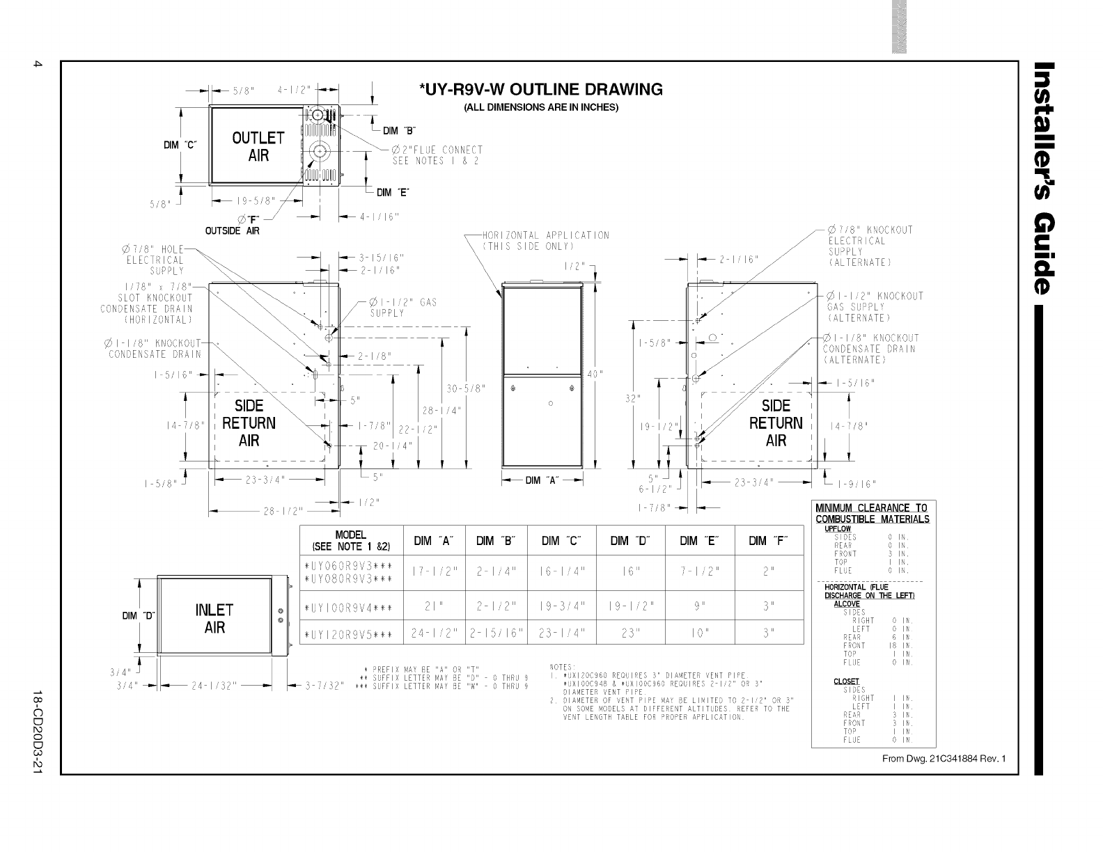
LOCATION AND CLEARANCES
The location of the furnace is normally selected by the
architect, the builder, or the installer. However, before the
furnace is moved into place, be sure to consider the following
requirements:
1. Is the location selected as near the chimney or vent and
as centralized for heat distribution as practical?
2. Do all clearances between the furnace and enclosure
equal or exceed the minimums stated in Clearance Table
on the Outline Drawings.
3. Is there sufficient space for servicing the furnace and
other equipment? A minimum of 24 inches front accessi-
bility to the furnace must be provided. Any access door or
panel must permit removal of the largest component.
4. Are there at least 3 inches of clearance between the
furnace combustion air openings in the front panel and
any closed panel or door provided?
5. Are the ventilation and combustion air openings large
enough and will they remain unobstructed? If outside air
is used, are the openings set above the highest snow
accumulation level? (See the Air for Combustion and
Ventilation section)
6. Allow sufficient height in supply plenum above the furnace
to provide for cooling coil installation, if the cooling coil is
not installed at the time of this furnace installation.
7. A furnace shall be installed so electrical components are
protected from water.
8. If the furnace is installed in a residential garage, it
must be installed so that the burners, and the ignition
source are located not less than 18 inches above the floor
and the furnace must be located or protected to avoid
physical damage from vehicles.
18-CD20D3-21
Installer's Guide
Contents
Installation Instructions
General Installation Instructions
Location and Clearances
Outline Drawing
Upflow Installation
Downflow Installations
Horizontal Installation
Air for Combustion and Ventilation
Duct Connections
Return Air Filters
General Venting Information
Venting Materials
High Altitude Derate
Horizontal Venting
Downward Venting
Venting Through the Roof
Venting Routed Through a Masonry Chimney
Electrical Connections
Field Wiring Diagrams
Condensate Drain Instructions
Gas Piping
Combustion and Input Check
Start-up and Adjustment
Preliminary Inspections
Lighting Instructions
Sequence of Operation
Control and Safety Switch Adjustments
Airflow Adjustment
Abnormal Conditions
IFC Error Flash Codes
Fault Code Recovery
IMPORTANT:
The furnace must be installed level The only allowable
variation would be slightly to the left and/or forward in upflow
installations or slightly toward the front in horizontal installa-
tions. This is necessary for proper condensate drainage.
Do not install the furnace in a corrosive or contaminated
atmosphere. Failure to follow this warning could result in
early equipment failure.
Do not install the furnace directly on carpeting, tile or other
combustible material other than wood flooring. For vertical
downflow application, subbase (BAYBASE205) must be
used between the furnace and combustible flooring. When
the downflow furnace is installed vertically with a cased coil,
a subbase is not required.
(3O
&
C1
1",3
o
C1
co
.i
14 7/8"
SIDE
i
, RETURN
AIR
DIM "B"
INLET Io
AIR °
?4 1'{57"
??
40"
a' @
o
DIM "A"
_C'}7,8" KtOCI{,OUT
ELECTFi IC_L
5UPPL','
_2 I 16" // (_LTEUi,LTE}
/,
f
SIDE
RETURN
AIR
MODEL
(SEE NOTE 1 &2)
÷LJYOGORgVS÷÷÷
÷L.YOOORgVS÷÷÷
_57
DIM "A" DIM "B" DIM "C" DIM "D" DIM "E" DIM "F"
I/ I/2" 2 I/4" IG I/4" 16" 7 1i2" P"
÷UYIOORgV4÷÷÷ 21" ? I/2" 19 3/4" 19 I/2" 9" 3"
÷UYIPOE!gVS÷÷÷ 24 I/2" 2 15/16" 23 I/4" 73" I0" 5"
÷ REFI: N# BE "A" O_ "T"
÷_ SUFFIX LETTER lqAf IIDII THRO 9
}_ II _@_ SUFFIX LETTER PlAY E IlWlI THRU a
NOTES
I ÷UXI20C960 REQUIRES 3" DIAMETER VENT PiPE
{UX100C948 & {UXIOOC960 REQUIRES 2 I/2" OR 3"
DIAMETER VENT PIPE
2 DIAMETER Of VENT PIPE MAY BE LIMITED TO 2 I/2" OR 3"
ON SOME MODELS AT DIFFERENT ALTITUDES REFER TO THE
VENT LENGTH TABLE FOR PROPER APPLICATIOB
_.,I I 2" FI, OCKOUT
(}AS SUP>L '
(ALTERNATE)
MINIMUM CLEARANCE TO
COMBUSTIBLE MATERIALS
UPFLOW
SIDES 0 IN
NEAR 0 IN
FRONT 5 IN
TOP I IN
FLuE 0 IN
HORIZONTAL(FLUE
DISCHARGEON THE LEF_
ALCOVE
SIDES
RIGHT 0 IN
LEFT 0 IN
REAR 6 IN
FRONT 18 IN
TOD I IN
FLOE O IN
CLOSET
SIDES
RIGHT I IN
LEFT I IN
REAR 3 IN
FRONT 3 IN
TOP I IN
FLOE 0 IN
From Dwg. 21C341884 Rev. 1
|
1tl
I-I,
Iit
I
I
II
n_
(3O
i
©
I-O
o
co
6
ol
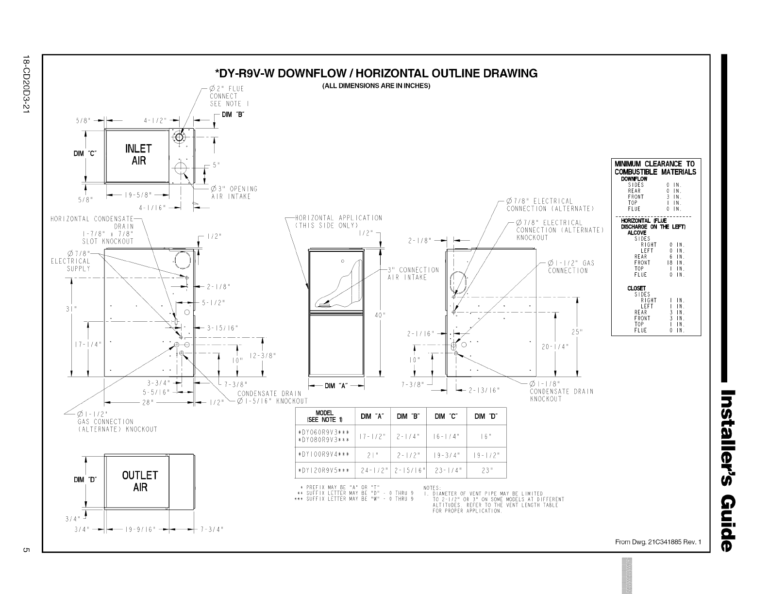
*DY-R9V-W DOWNFLOW /HORIZONTAL OUTLINE DRAWING
5/8" _
t
DIM "C"
_/8 II
4 1/2" _
INLET
19 5/8" _
41/16" _
?" FLUE
CONNECT
SEE NOTE I
¢3" OPENING
AIR INTAKE
NOR, ONTALCONDE fT
I 7/8" x 7/8"
SLOT KNOCKOUT
7/8"_
ELECTRICAL
SUPPLY
!_1/2"
_3 15/16"
DIM "D"
H
OUTLET
AIR
u
", I a_ _/I 6" _,"- 7 3/4"
(ALL DIMENSIONS ARE IN INCHES)
HORIZONTALAPPLICATION
(THIS SIDE ONLY)
\\\ I/2"
\\\\\\
CONNECTION
AIR INTAKE
40 "
7/8" ELECTRICAL
CONNECTION(ALTERNATE)
DIM "A"
MODEL DIM "A°
(SEE NOTE 1)
÷DY060RgVS÷÷÷
÷DY080Rgvs÷÷÷ I1 I/2"
÷DVl00Rgv4÷÷÷ 21"
÷DYI2OR9VS÷÷÷ 24 I/2"
DIM "e" DIM °C" DIM "D"
2 I/4" 16 I/4" 16"
2 I/2" 19 3/4" 19 I/2"
2 15/16 23 I/4" 23"
KNOCKOUT
_1 I/2" GAS
CONNECTION
25"
20 I/4"
CONDENSATE DRAIN
KNOCKOUT
PREFIX MAY BE "A" OR "T"
** SUFFIX LETTER MAY BE "D" O THRN 9
*** SUFFIX LETTER MAY BE IlWll 0 THRU 9
NOTES:
I DIAMETER OF VENT PIPE MAY BE LIMITED
TO 2 I/2" OR 3" ON SOME MODELS AT DIFFERENT
ALTITUDES REFER TO THE VENT LENGTH TABLE
FOR PROPER APPLICATION
MINIMUM CLEARANCE TO
COMBUSTIBLE MATERIALS
DOWNFLOW
SLOES 0 IN
REAR oIN.
FRONT 3 IN.
TOP I IN
FLUE 0 IN.
HORIZONTALFLUE
BSCHARGE ON 11-1ELB='E_
ALCOVE
SIDES
RIGHT 0 IN,
LEFT 0 IN.
REAR 6 IN
FRONT 18 IN,
TOP I IN.
FLUE 0 IN
CLOSET
SIDES
RIGHT I IN.
LEFT I IN
REAR 3 IN,
FRONT 3 IN.
TOP I I N.
FLUE 0 IN,
From Dwg. 21C341885 Rev. 1
|
I
I
(I}
m"
II
n_
(D
iiiiiiiiiiii
Installer's Guide
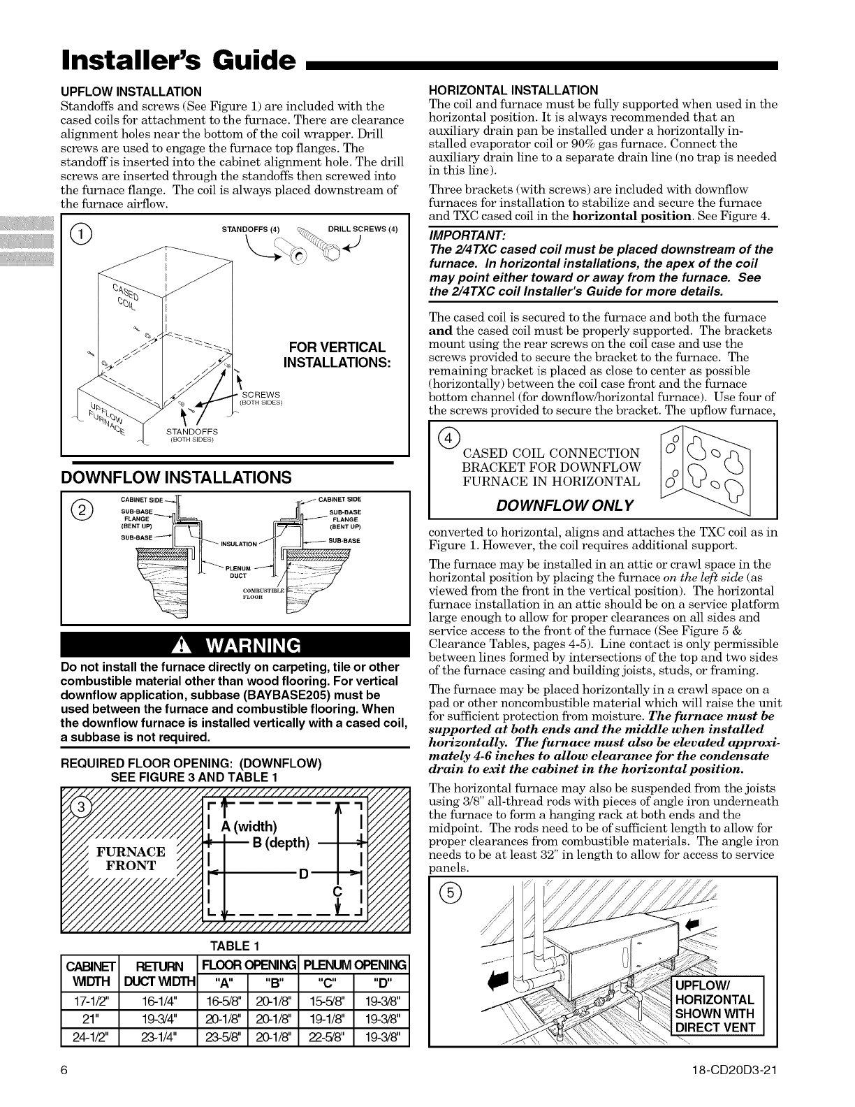
UPFLOW INSTALLATION
Standoffs and screws (See Figure 1) are included with the
cased coils for attachment to the furnace. There are clearance
alignment holes near the bottom of the coil wrapper. Drill
screws are used to engage the furnace top flanges. The
standoff is inserted into the cabinet alignment hole. The drill
screws are inserted through the standoffs then screwed into
the furnace flange. The coil is always placed downstream of
the furnace airflow.
STANDOFFS (4) DRILL SCREWS (4)
J
STANDOFFS
(BOTH SIDES)
FOR VERTICAL
INSTALLATIONS:
SCREWS
(BOTH SIDES)
DOWNFLOW INSTALLATIONS
@CABINET BIDE _CABINET SIDE
SUB-BASE SUB-BASE
FLANGE _FLANGE
(BENT UP) I_-- (BENT UP)
SUB-BASE _ i SUB-BASE
PLENUM
_--J-_DUCT
CO_mCSTmI,E
FLOOtl
Do not install the furnace directly on carpeting, tile or other
combustible material other than wood flooring. For vertical
downflow application, subbase (BAYBASE205) must be
used between the furnace and combustible flooring. When
the downflow furnace is installed vertically with a cased coil,
a subbase is not required.
REQUIRED FLOOR OPENING: (DOWNFLOW)
SEE FIGURE 3 AND TABLE 1
CABINET
WIDTH
17-1/2"
21"
24-1/2"
TABLE 1
RETURN FLOOR OPENING PLENUM OPENING
DUCT WIDTH "A.... B.... C.... D"
16-1/4" 16-5/8" 20-1/8" 15-5/8" 19-3/8"
19-3/4" 20-1/8" 20-1/8" 19-1/8" 19-3/8"
23-1/4" 23-5/8" 20-1/8" 22-5/8" 19-3/8"
HORIZONTAL INSTALLATION
The coil and furnace must be fully supported when used in the
horizontal position. It is always recommended that an
auxiliary drain pan be installed under a horizontally in-
stalled evaporator coil or 90% gas furnace. Connect the
auxiliary drain line to a separate drain line (no trap is needed
in this line).
Three brackets (with screws) are included with downflow
furnaces for installation to stabilize and secure the furnace
and TXC cased coil in the horizontal position. See Figure 4.
IMPORTANT:
The 2/4TXC cased coil must be placed downstream of the
furnace. In horizontal installations, the apex of the coil
may point either toward or away from the furnace. See
the 2/4TXC coil Installer's Guide for more details.
The cased coil is secured to the furnace and both the furnace
and the cased coil must be properly supported. The brackets
mount using the rear screws on the coil case and use the
screws provided to secure the bracket to the furnace. The
remaining bracket is placed as close to center as possible
(horizontally) between the coil case front and the furnace
bottom channel (for downflow/horizontal furnace). Use four of
the screws provided to secure the bracket. The upflow furnace
CASED COIL CONNECTION _ I
BRACKET FOR DOWNFLOW
FURNACE IN HORIZONTAL
DOWNFLOW ONLY
converted to horizontal, aligns and attaches the TXC coil as in
Figure 1. However, the coil requires additional support.
The furnace may be installed in an attic or crawl space in the
horizontal position by placing the furnace on the left side (as
viewed from the front in the vertical position). The horizontal
furnace installation in an attic should be on a service platform
large enough to allow for proper clearances on all sides and
service access to the front of the furnace (See Figure 5 &
Clearance Tables, pages 4-5). Line contact is only permissible
between lines formed by intersections of the top and two sides
of the furnace casing and building joists, studs, or framing.
The furnace may be placed horizontally in a crawl space on a
pad or other noncombustible material which will raise the unit
for sufficient protection from moisture. The furnace must be
supported at both ends and the middle when installed
horizontally. The furnace must also be elevated approxi-
mately 4-6 inches to allow clearance for the condensate
drain to exit the cabinet in the horizontal position.
The horizontal furnace may also be suspended from the joists
using 3/8" all-thread rods with pieces of angle iron underneath
the furnace to form a hanging rack at both ends and the
midpoint. The rods need to be of sufficient length to allow for
proper clearances from combustible materials. The angle iron
needs to be at least 32" in length to allow for access to service
)anels.
@
6 18-CD20D3-21
®
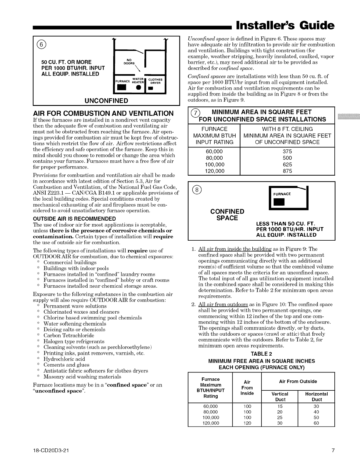
50 CU. FT. OR MORE
PER 1000 BTU/HR. INPUT
ALL EQUIP. INSTALLED
w,t..IoLo,,.s
UNCONFINED
AIR FOR COMBUSTION AND VENTILATION
If these furnaces are installed in a nondirect vent capacity
then the adequate flow of combustion and ventilating air
must not be obstructed from reaching the furnace. Air open-
ings provided for combustion air must be kept free of obstruc-
tions which restrict the flow of air. Airflow restrictions affect
the efficiency and safe operation of the furnace. Keep this in
mind should you choose to remodel or change the area which
contains your furnace. Furnaces must have a free flow of air
for proper performance.
Provisions for combustion and ventilation air shall be made
in accordance with latest edition of Section 5.3, Air for
Combustion and Ventilation, of the National Fuel Gas Code,
ANSI Z223.1 -- CAN/CGA B149.1 or applicable provisions of
the local building codes. Special conditions created by
mechanical exhausting of air and fireplaces must be con-
sidered to avoid unsatisfactory furnace operation.
OUTSIDE AIR IS RECOMMENDED
The use of indoor air for most applications is acceptable,
unless there is the presence of corrosive chemicals or
contamination. Certain types of installation will require
the use of outside air for combustion.
The following types of installations will require use of
OUTDOOR AIR for combustion, due to chemical exposures:
* Commercial buildings
* Buildings with indoor pools
* Furnaces installed in "confined" laundry rooms
* Furnaces installed in "confined" hobby or craft rooms
* Furnaces installed near chemical storage areas.
Exposure to the following substances in the combustion air
supply will also require OUTDOOR AIR for combustion:
* Permanent wave solutions
* Chlorinated waxes and cleaners
* Chlorine based swimming pool chemicals
* Water softening chemicals
* Deicing salts or chemicals
* Carbon Tetrachloride
* Halogen type refrigerants
* Cleaning solvents (such as perchloroethylene)
* Printing inks, paint removers, varnish, etc.
* Hydrochloric acid
* Cements and glues
* Antistatic fabric softeners for clothes dryers
* Masonry acid washing materials
Furnace locations may be in a "confined space" or an
"unconfined space".
Installer's Guide
Unconfined space is defined in Figure 6. These spaces may
have adequate air by infiltration to provide air for combustion
and ventilation. Buildings with tight construction (for
example, weather stripping, heavily insulated, caulked, vapor
barrier, etc.), may need additional air to be provided as
described for confined space.
Confined spaces are installations with less than 50 cu. ft. of
space per 1000 BTU/hr input from all equipment installed.
Air for combustion and ventilation requirements can be
supplied from inside the building as in Figure 8 or from the
outdoors, as in Figure 9.
_F MINIMUM AREA IN SQUARE FEET
OR UNCONFINED SPACE INSTALLATIONS
FURNACE WITH 8 FT. CEILING
MAXIMUM BTUH MINIMUM AREA IN SQUARE FEET
INPUT RATING OF UNCONFINED SPACE
60,000 375
80,000 500
100,000 625
120,000 875
I--I-
1.
2.
CONFINED
SPACE LESS THAN 50 CU. FT.
PER 1000 BTU/HR. INPUT
ALL EQUIP. INSTALLED
All air from inside the building as in Figure 9: The
confined space shall be provided with two permanent
openings communicating directly with an additional
room(s) of sufficient volume so that the combined volume
of all spaces meets the criteria for an unconfined space.
The total input of all gas utilization equipment installed
in the combined space shall be considered in malting this
determination. Refer to Table 2 for minimum open areas
requirements.
All air from outdoors as in Figure 10: The confined space
shall be provided with two permanent openings, one
commencing within 12 inches of the top and one com-
mencing within 12 inches of the bottom of the enclosure.
The openings shall communicate directly, or by ducts,
with the outdoors or spaces (crawl or attic) that freely
communicate with the outdoors. Refer to Table 2, for
minimum open areas requirements.
TABLE 2
MINIMUM FREE AREA IN SQUARE INCHES
EACH OPENING FURNACE ONLY)
Furnace
Maximum
BTUH/INPUT
Rating
60,000
80,000
100,000
120,000
Air
From
Inside
1oo
1oo
1oo
120
Air From Outside
Vertical
Duct
15
20
25
30
Horizontal
Duct
30
40
50
60
18-CD20D3-21 7
iiiiiiiiiiii
Installer's Guide
®
CONFINED SPACE
AIR FROM INSIDE BUILDING
CONFINED
SPACE
PERMANENT
OPENINGS
_J
®
CONFINED SPACE
AIR FROM OUTDOORS
L
CONFINED-
SPACE
CONFINED SPACE k
AIR FROM VENTILATED ATTIC/CRAWL SPACE
_ATTIC LOUVERS
DOORS
,UTLET
CONFINED -AIR
SPACE
ALTERNATE INLET
INLET A_R _AIR DUCT
CONFINED SPACE
AIR FROM VENTILATED ATTIC
:LOUVERS
TO OUTDOORS
CONFINED-
SPACE
INLET
AIR DUCT
DUCT CONNECTIONS
Air duct systems should be installed in accordance with
standards for air conditioning systems, National Fire
Protection Association Pamphlet No. 90. They should be
sized in accordance with ACCA Manual D or whichever is
applicable.
Central furnaces, when used in connection with cooling units,
shall be installed in parallel or on the upstream side of the
cooling coil to avoid condensation in the heat exchanger. With a
parallel flow arrangement, the dampers or other means used
to control flow of air shall be adequate to prevent chilled air
from entering the furnace, and if manually operated, must be
equipped with means to prevent operation of either unit
unless the damper is in full heat or cool position.
On any job, flexible connections of nonflammable material may
be used for return air and discharge connections to prevent
transmission of vibration. Though these units have been spe-
cifically designed for quiet, vibration free operation, air ducts
can act as sounding boards and could, if poorly installed, am-
plify the slightest vibration to the annoyance level.
When the furnace is located in a utility room adjacent to the
living area, the system should be carefully designed with
returns to minimize noise transmission through the return
air grille. Although these furnaces are designed with large
blowers operating at moderate speeds, any blower moving a
high volume of air will produce audible noise which could be
objectionable when the unit is located very close to a living
area. It is often advisable to route the return air ducts under
the floor or through the attic. Such design permits the
installation of air return remote from the living area
(i.e. central hall).
When the furnace is installed so that the supply ducts carry
air circulated by the furnace to areas outside the space
containing the furnace, the return air shall also be handled by
a duct(s) sealed to the furnace and terminating outside the
space containing the furnace.
RETURN AIR DUCT SYSTEMS
Where there is no complete return duct system, the
return connection must be run full size from the fur-
nace to a location outside the utility room, basement,
attic, or crawl space.
Do Not install return air through the back of the furnace
cabinet.
Do Not install return air through the side of the [hrnace cabinet
on horizontal applications.
NOTE:
Minimum return air temperature is 55 °F.
All return air duct systems should provide for installation of
return air filters.
1. Set the furnace in place.
2. For upflow side return installations, remove the insulation
around the opening in the blower compartment.
3. The side panels of the upflow furnace include locating
notches that are used as guides for cutting an opening for
return air, refer to Figure 11 and the outline drawing on
page 4 for duct connection dimensions for various
furnaces.
4. Ifa 3/4" flange is to be used for attaching the air inlet
duct, add to cut where indicated by dotted lines in
Figure 11. Cut corners diagonally and bend outward to
form flange.
5. If flanges are not required, and a filter frame is installed,
cut between locating notches (See Figure 11).
6. The bottom panel of the upflow furnace must be removed
for bottom return air.
8 18-CD20D3-21
Remove the filter and lay the furnace on its back. Remove
the two 1/4" hex screws securing the bottom front channel
to the cabinet. Lower the front edge of the bottom front
channel and pull forward to remove the channel. The
bottom return air panel will now easily slide out of the
cabinet. Reinstall the bottom front channel and filter for
upflow bottom return installations.
7. The filter retainer is factory supplied for upflow bottom
return. Use the filter retainer on side or bottom if filter is
to be used within the furnace cabinet on upflow only
installations.
8. The horizontal installation of the upflow furnace
requires an external filter section. Do NOT use the
bottom return filter within the furnace. Filter kits
are available for horizontal applications.
9. Connect duct work to furnace. See Outline Drawing for
supply and return duct size and location. Flexible duct
connectors are recommended to connect both supply and
return air ducts to the furnace. If only the front of the
furnace is accessible, it is recommended that both supply
and return air plenums are removable.
RETURN AIR FILTERS
TYPICAL UPFLOW RETURN AIR FILTER INSTALLATIONS
Filters are factory supplied for these furnaces. These fur-
naces require high velocity type air filters. The filters may be
located within the furnace blower compartment for UPFLOW
furnaces in either a BOTTOM or SIDE (left side or right side)
return air inlet. Some filters may need to be trimmed for side
or bottom filter use.
TABLE 3
MODELS CABINET FILTER
NUMBERS WIDTH QTY & SIZE
*UYO6OR9V3
*UYO8OR9V3 17-1/2" 1 -17"X 25"X 1"
*UYIOOR9V4 21" 1 -20" X 25" X 1"
*UY120R9V5 24-1/2" 1 -24"X 25"X 1"
* First letter may be "A" or "T"
** NOTE - On 5 ton airflow models, if the airflow requirement
exceeds 1800 CFM, these models will require return air openings
and filters on both sides; OR 1 side and the bottom; OR just the
bottom.
NOTE:
On upflow 5 ton airflow models, if the airflow requirement
exceeds 1800 CFM, these models will require return air
openings and filters on both sides; OR I side and the
bottom; OR just the bottom.
®UPFLOW FURNACE ONLY
LOCATING *'_
NOTCHES PRO-"T.,.
VIDED FOR SIDETI
RETURN CUTOUT
I
-. Ij
J
I
CUT OUT FOR
J SIDE FILTER
ONT
/of Furnace
*SEE OUTLINE DRAWING
Installer's Guide
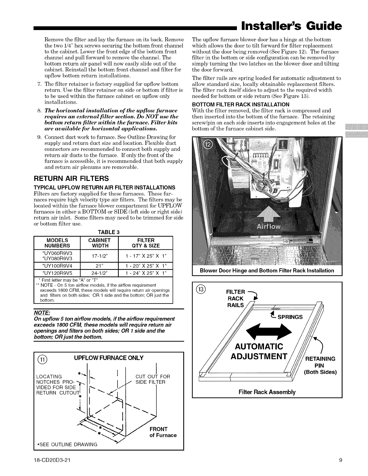
The upflow furnace blower door has a hinge at the bottom
which allows the door to tilt forward for filter replacement
without the door being removed (See Figure 12). The furnace
filter in the bottom or side configuration can be removed by
simply turning the two latches on the blower door and tilting
the door forward.
The filter rails are spring loaded for automatic adjustment to
allow standard size, locally obtainable replacement filters.
The filter rack itself slides to adjust to the required width
needed for bottom or side return (See Figure 13).
BOTTOM FILTER RACK INSTALLATION
With the filter removed, the filter rack is compressed and
then inserted into the bottom of the furnace. The retaining
screw/pin on each side inserts into engagement holes at the
bottom of the furnace cabinet side.
Blower Door Hinge and Bottom Filter Rack Installation
®FILTER
RACK -'_
RAILS _?
4__SPRINGS
ADJUSTMEN TAINING
-_// PI;ides)
(Both
Filter Rack Assembly
18-CD20D3-21 9
iiiiiiiiiiii
Installer's Guide
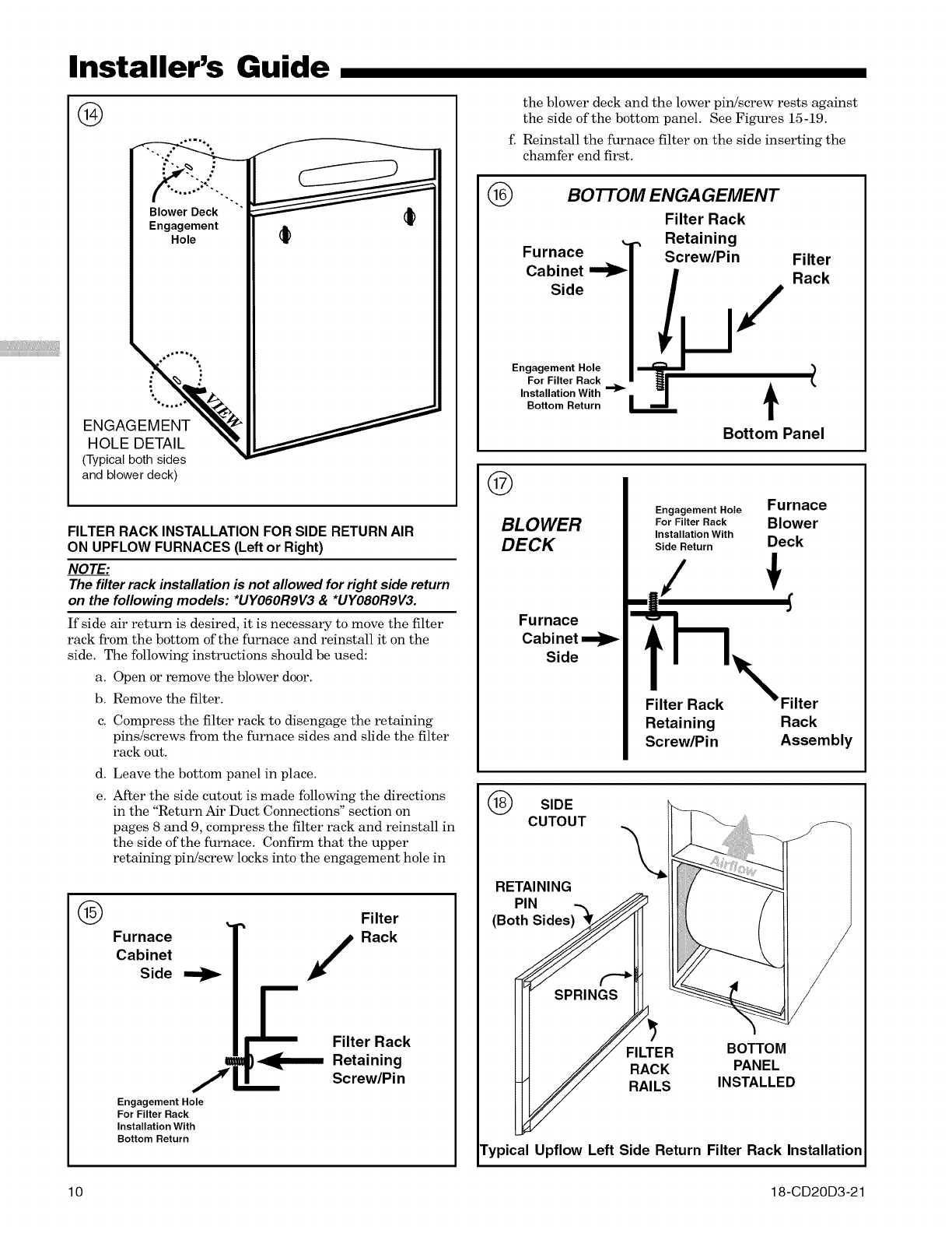
®
-. : ""'"';
Engagement II _
iiiII
tlV
%.,,
ENGAGEMENT
HOLE DETAIL
(Typical both sides
and blower deck)
FILTER RACK INSTALLATION FOR SIDE RETURN AIR
ON UPFLOW FURNACES (Left or Right)
NOTE:
The filter rack installation is not allowed for right side return
on the following models: *UYO6ORDV3 & *UYO8ORDV3.
If side air return is desired, it is necessary to move the filter
rack from the bottom of the furnace and reinstall it on the
side. The following instructions should be used:
a. Open or remove the blower door.
b. Remove the filter.
c. Compress the filter rack to disengage the retaining
pins/screws from the furnace sides and slide the filter
rack out.
d. Leave the bottom panel in place.
e. After the side cutout is made following the directions
in the "Return Air Duct Connections" section on
pages 8 and 9, compress the filter rack and reinstall in
the side of the furnace. Confirm that the upper
retaining pin/screw locks into the engagement hole in
(_ Filter
Furnace
Cabinet
Side Rack
Filter Rack
7_ _1_......_ Retaining
Screw/Pi n
Engagement Hole
For Filter Rack
Installation With
Bottom Return
the blower deck and the lower pin/screw rests against
the side of the bottom panel. See Figures 15-19.
f. Reinstall the furnace filter on the side inserting the
chamfer end first.
®
Furnace
Cabinet
Side
BOTTOM ENGAGEMENT
Filter Rack
., Retaining
Screw/Pin
r
Engagement Hole
For Filter Rack
Installation With _)_
Bottom Return
/
t
Filter
Rack
)
Bottom Panel
®
BLOWER
DECK
Furnace
Cabi net
Side
Engagement Hole Furnace
For Filter Rack Blower
Installation With
Side Return Deck
_./
_N Filter
Retaining Rack
Screw/Pin Assembly
(_ SIDE
CUTOUT
RETAINING \
BOTTOM
PANEL
INSTALLED
Typical Upflow Left Side Return Filter Rack Installation
10 18-CD20D3-21
Installer's Guide
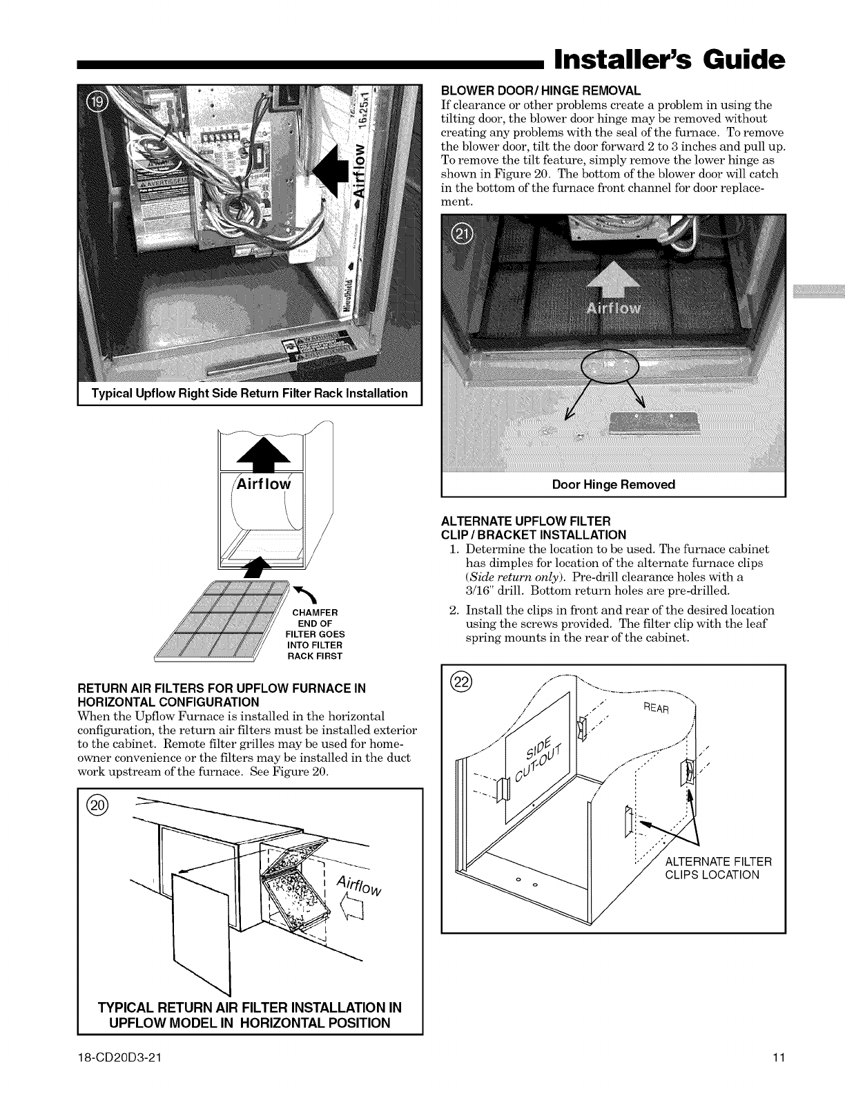
BLOWER DOOR/HINGE REMOVAL
Ifclearance or other problems create a problem in using the
tiltingdoor, the blower door hinge may be removed without
creating any problems with the sealof the furnace. To remove
the blower door, tiltthe door forward 2 to 3 inches and pull up.
To remove the tiltfeature,simply remove the lower hinge as
shown in Figure 20. The bottom of the blower door willcatch
in the bottom ofthe furnace front channel fordoor replace-
ment.
Typical Upflow Right Side Return Filter Rack Installation
CHAMFER
END OF
FILTER GOES
INTO FILTER
RACK FIRST
RETURN AIR FILTERS FOR UPFLOW FURNACE IN
HORIZONTAL CONFIGURATION
When the Upflow Furnace is installed in the horizontal
configuration, the return air filters must be installed exterior
to the cabinet. Remote filter grilles may be used for home-
owner convenience or the filters may be installed in the duct
work upstream of the furnace. See Figure 20.
f_
TYPICAL RETURN AIR FILTER INSTALLATION IN
UPFLOW MODEL IN HORIZONTAL POSITION
Door Hinge Removed
ALTERNATE UPFLOW FILTER
CLIP /BRACKET INSTALLATION
1. Determine the location to be used. The furnace cabinet
has dimples for location of the alternate furnace clips
(Side return only). Pre-_'ill clearance holes with a
3/16" drill. Bottom return holes are pre-drilled.
2. Install the clips in front and rear of the desired location
using the screws provided. The filter clip with the leaf
spring mounts in the rear of the cabinet.
@
ALTERNATE FILTER
CLIPS LOCATION
18-CD20D3-21 11
Installer's Guide
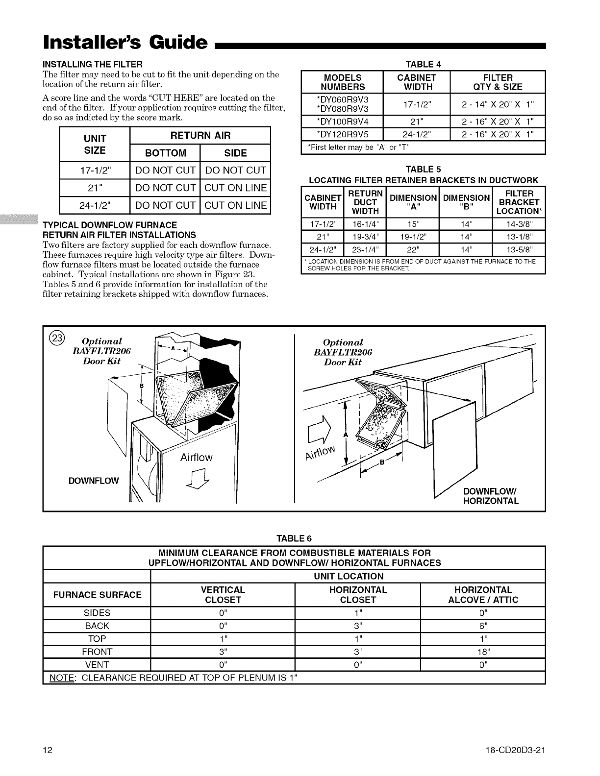
INSTALLING THE FILTER
The filter may need to be cut to fit the unit depending on the
location of the return air filter.
A score line and the words "CUT HERE" are located on the
end of the filter. If your application requires cutting the filter,
do so as indicted by the score mark.
UNIT
SIZE
17-1/2"
21"
24-1/2"
BOTTOM
DO NOT CUT
DO NOT CUT
DO NOT CUT
RETURN AIR
SIDE
DO NOT CUT
CUT ON LINE
CUT ON LINE
TYPICAL DOWNFLOW FURNACE
RETURN AIR FILTER INSTALLATIONS
Two filters are factory supplied for each downflow furnace.
These furnaces require high velocity type air filters. Down-
flow furnace filters must be located outside the furnace
cabinet. Typical installations are shown in Figure 23.
Tables 5 and 6 provide information for installation of the
filter retaining brackets shipped with downflow furnaces.
TABLE 4
MODELS CABINET FILTER
NUMBERS WIDTH QTY & SIZE
*DY060R9V3
*DY080R9V3 17-1/2" 2 - 14" X 20" X 1"
*DY100R9V4 21" 2 - 16" X 20" X 1"
*DY120R9V5 24-1/2" 2 - 16" X 20" X 1"
*First letter may be "A"or "T"
TABLE 5
LOCATING FILTER RETAINER BRACKETS IN DUCTWORK
RETURN FILTER
CABINET DIMENSION DIMENSION
WIDTH DUCT "A .... B" BRACKET
WIDTH LOCATION*
17-1/2" 16-1/4" 15" 14" 14-3/8"
21" 19-3/4" 19-1/2" 14" 13-1/8"
24-1/2" 23-1/4" 22" 14" 13-5/8"
* LOCATION DIMENSION IS FROM END OF DUCT AGAINST THE FURNACE TO THE
SCREW HOLES FOR THE BRACKET
OOptional
BAYFL TR206
Door Kit
DOWNFLOW
Airflow
Optional
BAYFL TR206 _
TABLE 6
MINIMUM CLEARANCE FROM COMBUSTIBLE MATERIALS FOR
UPFLOW/HORIZONTAL AND DOWNFLOW/HORIZONTAL FURNACES
UNIT LOCATION
VERTICAL HORIZONTAL HORIZONTAL
FURNACE SURFACE CLOSET CLOSET ALCOVE /ATTIC
SIDES 0" 1" 0"
BACK 0" 3" 6"
TOP 1" 1" 1"
FRONT 3" 3" 18"
VENT 0" 0" 0"
NOTE: CLEARANCE REQUIRED AT TOP OF PLENUM IS 1"
12 18-CD20D3-21
Installer's Guide
GENERAL VENTING INFORMATION
THIS FURNACE MUST BE VENTED TO THE OUTDOORS.
THESE FURNACES ARE INDUCED DRAFT VENTED
AND MUST NOT BE CONNECTED TO ANY VENT
SERVING ANOTHER APPLIANCE. PLEASE NOTE THAT
THESE FURNACES USE POSITIVE-PRESSURE VENT
SYSTEMS.
Proper venting is essential to obtain maximum efficiency
from a condensing furnace. Proper installation of the vent
system is necessary to assure drainage of the condensate and
prevent deterioration of the vent system.
American Gas Association has certified the design of condens-
ing furnaces for a minimum of 0" clearance from combustible
materials with a single wall plastic vent pipe.
The recommended system is assembled from 2", 2-1/2", or
3" plastic pipe and fittings (See Table 7, page 15). Where
the system is routed to the outdoors through an existing
masonry chimney containing flue products from another
gas appliance, or where required by local codes, then
3" venting of Type 29-4C stainless steel must be used in
place of PVC material.
These furnaces have been classified as CATEGORY IV
furnaces in accordance with ANSI Z21.47 "latest edition"
standards. Category IV furnaces operate with positive vent
pressure and with a vent gas temperature less than 140 ° F.
above the dewpoint. These conditions require special venting
systems, which must be gas tight and water tight.
NOTE:
When an existing furnace is removed from a venting system
serving other gas appliances, the venting system is likely to
be too large to properly vent the remaining attached appli-
ances.
The following steps shall be followed with each appliance
remaining connected to the common venting system placed in
operation, while the other appliances remaining connected to
the common venting system are not in operation.
1. Seal any unused openings in the common venting system.
2. Visually inspect the venting system for proper size and
horizontal pitch and determine there is no blockage or
restriction, leakage, corrosion or other deficiencies which
could cause an unsafe condition.
3. Insofar as is practical, close all building doors and
windows and all doors between the space in which the
appliances remaining connected to the common venting
system are located and other spaces of the building. Turn
on clothes dryers and any appliances not connected to the
common venting system. Turn on any exhaust fans, such
as range hoods and bathroom exhausts, so they will
operate at maximum speed. Do not operate a summer
exhaust fan, close fireplace dampers.
4. Follow the lighting instructions. Place the appliance
being inspected in operation. Adjust thermostat so
appliance will operate continuously.
5. Test for spillage at the draft hood relief opening after
5 minutes of main burner operation. Use the flame of a
match or candle, or smoke from a cigarette, cigar, or pipe.
6. After it has been determined that each appliance remain-
ing connected to the common venting system properly
vents when tested as outlined above, return door, win-
dows, exhaust fans, fireplace dampers and any other gas-
burning appliance to their previous conditions of use.
If improper venting is observed during any of the above tests,
the remaining common venting system must be corrected.
Correction could require rerouting or resizing the remaining
vent system.
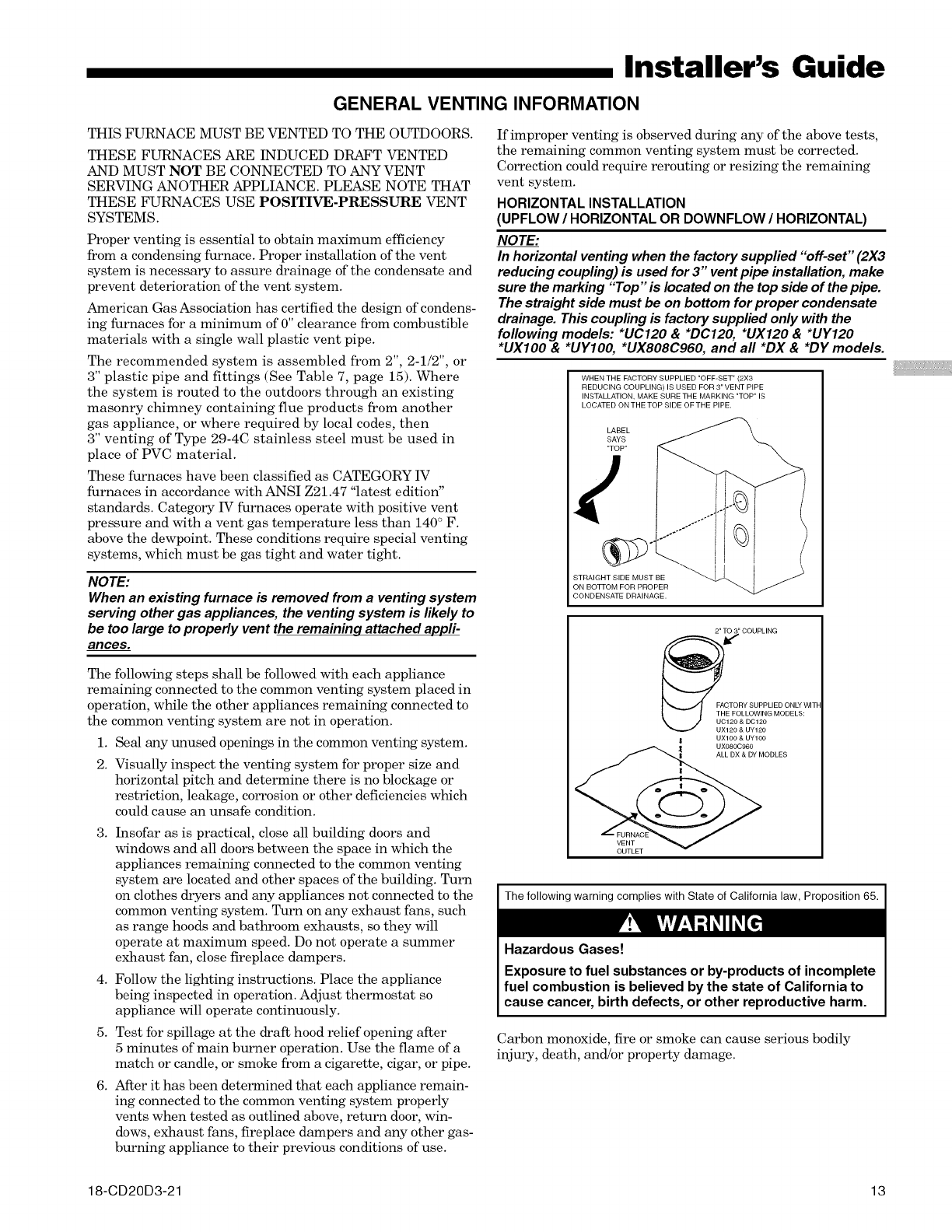
HORIZONTAL INSTALLATION
(UPFLOW /HORIZONTAL OR DOWNFLOW /HORIZONTAL)
NOTE:
In horizontal venting when the factory supplied "off-set" (2X3
reducing coupling) is used for 3" vent pipe installation, make
sure the marking "Top" is located on the top side of the pipe.
The straight side must be on bottom for proper condensate
drainage. This coupling is factory supplied only with the
following models: *UC120 & *DC120, *UX120 & *UY120
*UXIO0 & *UYIO0, *UX808C960, and all *DX & *DY models.
WHEN THE FACTORY SUPPLIED "OFF-SET" (2X3
REDUCING COUPLING) IS USED FOR 3" VENT PIPE
INSTALLATION, MAKE SURETHE MARKING "TOP" IS
LOCATED ON THETOP SIDE OFTHE PIPE.
LABEL
SAYS
"TOP"
STRAIGHT SIDE MUST BE
ON BOTTOM FOR PROPER
CONDENSATE DRAINAGE.
2" ,_' COUPLING
FACTORY SUPPLIED ONLY WITF
T_E FOLLOWING MODELS:
UC120 & DC120
120 & UY120
| UXl00 & UY100
UX080C960
MODLES
VENT
VENTET V
I The following warning complies with State of California law, Proposition 65.
Hazardous Gases!
Exposure to fuel substances or by-products of incomplete
fuel combustion is believed by the state of California to
cause cancer, birth defects, or other reproductive harm.
Carbon monoxide, fire or smoke can cause serious bodily
injury, death, and!or property damage.
18-CD20D3-21 13
Installer's Guide
A variety of potential sources of carbon monoxide can be found in a building or dwelling such as gas-fired clothes dryers, gas
cooking stoves, water heaters, furnaces and fireplaces. The U.S. Consumer Product Safety Commission recommends that users
of gas-burning appliances install carbon monoxide detectors as well as fire and smoke detectors per the manufacturer's
installation instructions to help alert dwelling occupants of the presence of fire, smoke or unsafe levels of carbon monoxide.
These devices should be listed by Underwriters Laboratories, Inc. Standards fbr Single and Multiple Station Carbon Monoxide
Alarms, UL 2034 or CSA International Standard, Residential Carbon Monoxide Alarming Devices, CSA 6.19
NOTE: The manufacturer of your furnace does not test any detectors and makes no representations regarding any brand
or type of detector.
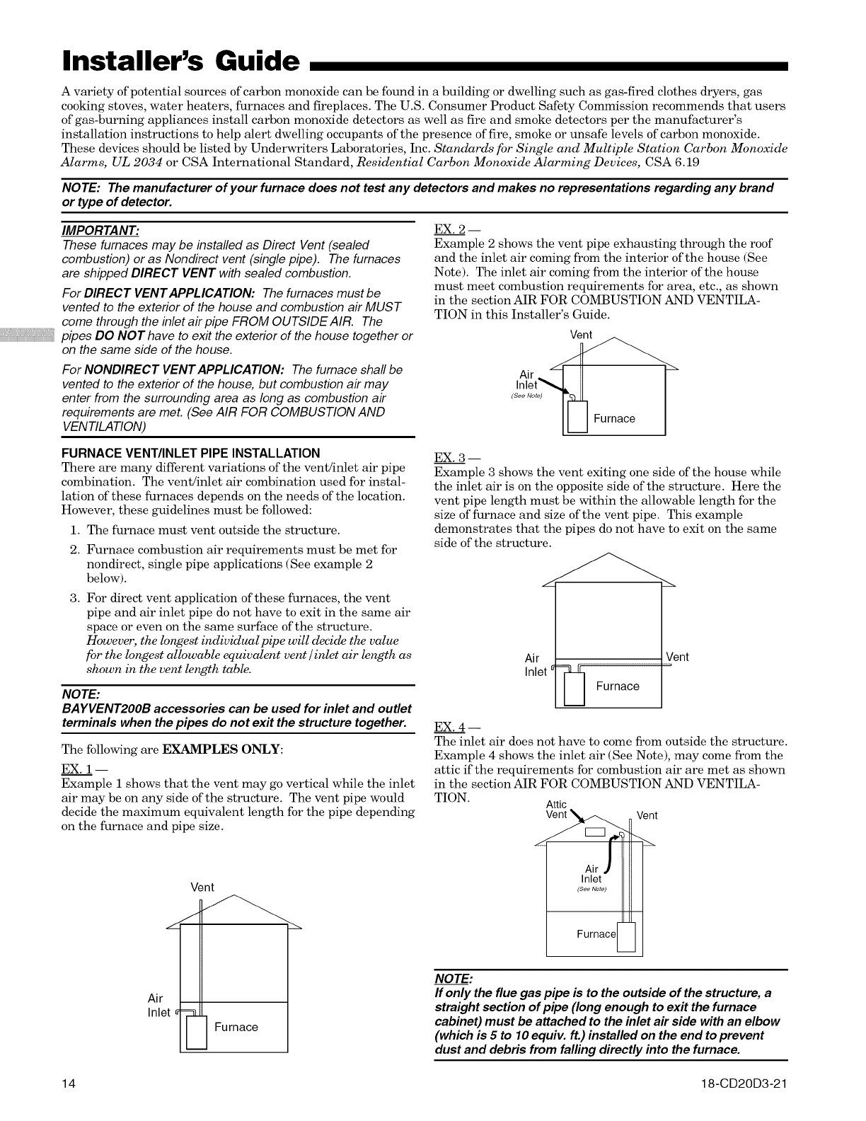
IMPORTANT:
These furnaces may be installed as Direct Vent (sealed
combustion) or as Nondirect vent (single pipe). The furnaces
are shipped DIRECT VENT with sealed combustion.
For DIRECT VENT APPLICATION: The fumaces must be
vented to the exterior of the house and combustion air MUST
come through the inlet air pipe FROM OUTSIDE AIR. The
pipes DO NOT have to exit the exterior of the house together or
on the same side of the house.
For NONDIRECT VENT APPLICATION: The furnace shall be
vented to the exterior of the house, but combustion air may
enter from the surrounding area as long as combustion air
requirements are met. (See AIR FOR COMBUSTION AND
VENTILATION)
FURNACE VENT/INLET PIPE INSTALLATION
There are many different variations of the vent/inlet air pipe
combination. The vent/inlet air combination used for instal-
lation of these furnaces depends on the needs of the location.
However, these guidelines must be followed:
1. The furnace must vent outside the structure.
2. Furnace combustion air requirements must be met for
nondirect, single pipe applications (See example 2
below).
3. For direct vent application of these furnaces, the vent
pipe and air inlet pipe do not have to exit in the same air
space or even on the same surface of the structure.
However, the longest individual pipe will decide the value
fbr the longest allowable equivalent vent/inlet air length as
shown in the vent length table.
NOTE:
BAYVENT2OOB accessories can be used for inlet and outlet
terminals when the pipes do not exit the structure together.
The following are EXAMPLES ONLY:
EX. 1-
Example 1 shows that the vent may go vertical while the inlet
air may be on any side of the structure. The vent pipe would
decide the maximum equivalent length for the pipe depending
on the furnace and pipe size.
Air
Inlet
Vent
Furnace
EX. 2--
Example 2 shows the vent pipe exhausting through the roof
and the inlet air coming from the interior of the house (See
Note). The inlet air coming from the interior of the house
must meet combustion requirements for area, etc., as shown
in the section AIR FOR COMBUSTION AND VENTILA-
TION in this Installer's Guide.
Vent
Inlet",,4 II I
(seeNot_ [_[L] Furnace
EX. 3 --
Example 3 shows the vent exiting one side of the house while
the inlet air is on the opposite side of the structure. Here the
vent pipe length must be within the allowable length for the
size of furnace and size of the vent pipe. This example
demonstrates that the pipes do not have to exit on the same
side of the structure.
Air
Inlet _L I Furnace
Vent
EX. 4--
The inlet air does not have to come from outside the structure.
Example 4 shows the inlet air (See Note), may come from the
attic if the requirements for combustion air are met as shown
in the section AIR FOR COMBUSTION AND VENTILA-
TION. Attic
_ Vent
L _
Air jr
Inlet
(See Note)
Furnace[_
NOTE:
If only the flue gas pipe is to the outside of the structure, a
straight section of pipe (long enough to exit the furnace
cabinet) must be attached to the inlet air side with an elbow
(which is 5 to 10 equiv, ft.) installed on the end to prevent
dust and debris from falling directly into the furnace.
14 18-CD20D3-21
Installer's Guide
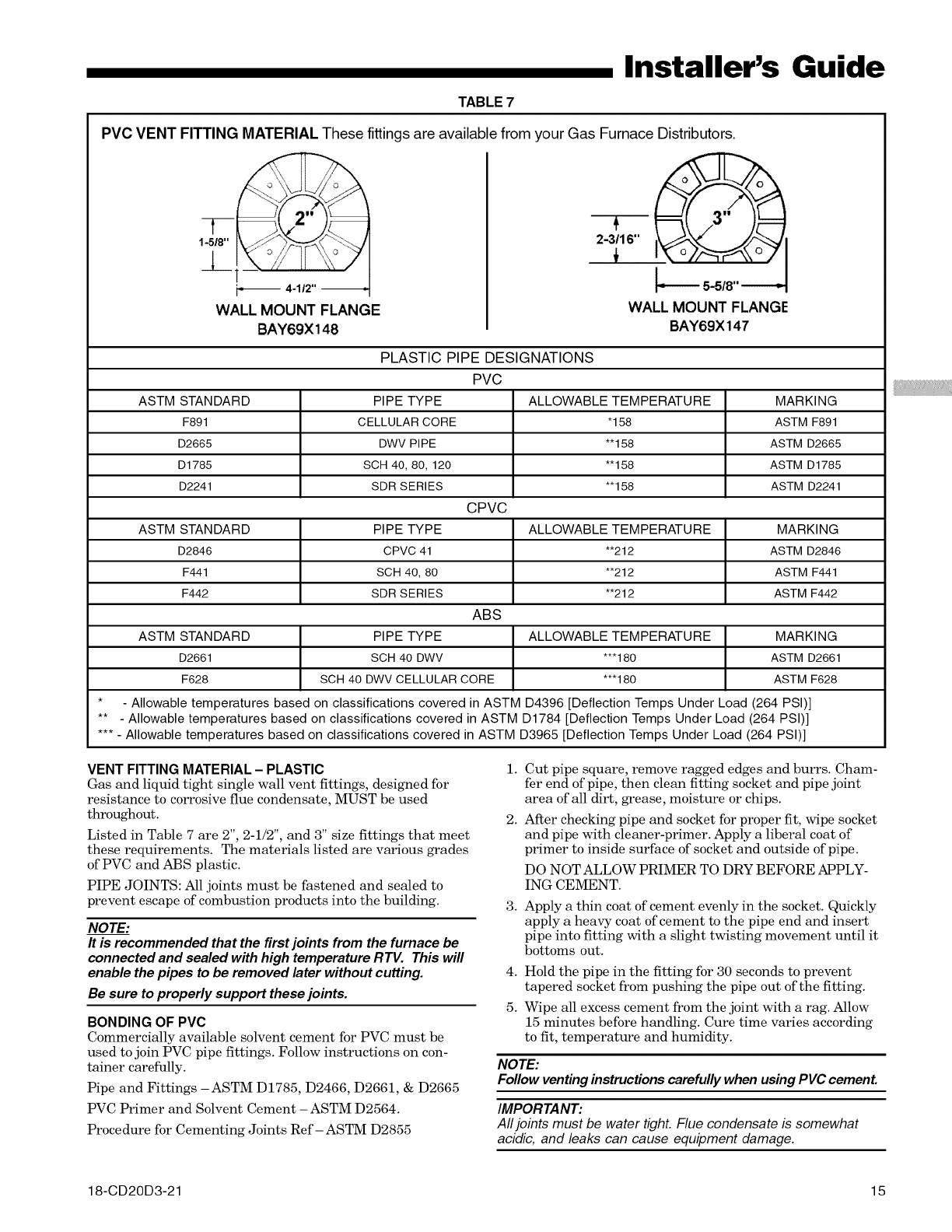
TABLE 7
PVC VENT FITTING MATERIAL These fittings are available from your Gas Furnace Distributors.
1-5/8"
J_____
WALL MOUNT FLANGE
BAY69X 148
2-3_16"
I'_---- 5-5/8"
WALL MOUNT FLANGE
BAY69X 147
PLASTIC PIPE DESIGNATIONS
PVC
ASTM STANDARD PIPE TYPE ALLOWABLE TEMPERATURE MARKING
F891 CELLULAR CORE "158 ASTM F891
D2665 DWV PIPE *'158 ASTM D2665
D1785 SCH 40, 80, 120 *'158 ASTM D1785
D2241 SDR SERIES *'158 ASTM D2241
CPVC
ASTM STANDARD PIPE TYPE ALLOWABLE TEMPERATURE MARKING
D2846 CPVC 41 *'212 ASTM D2846
F441 SCH 40, 80 *'212 ASTM F441
F442 SDR SERIES *'212 ASTM F442
ABS
ASTM STANDARD PIPE TYPE ALLOWABLE TEMPERATURE MARKING
D2661 SCH 40 DWV **'180 ASTM D2661
F628 SCH 40 DWV CELLULAR CORE **'180 ASTM F628
* - Allowable temperatures based on classifications covered in ASTM D4396 [Deflection Temps Under Load (264 PSI)]
** - Allowable temperatures based on classifications covered in ASTM D1784 [Deflection Temps Under Load (264 PSI)]
*** - Allowable temperatures based on classifications covered in ASTM D3965 [Deflection Temps Under Load (264 PSI)]
VENT FITTING MATERIAL- PLASTIC
Gas and liquid tight single wall vent fittings, designed for
resistance to corrosive flue condensate, MUST be used
throughout.
Listed in Table 7 are 2", 2-1/2", and 3" size fittings that meet
these requirements. The materials listed are various grades
of PVC and ABS plastic.
PIPE JOINTS: All joints must be fastened and sealed to
prevent escape of combustion products into the building.
NOTE:
It is recommended that the first joints from the furnace be
connected and sealed with high temperature RTV. This will
enable the pipes to be removed later without cutting.
Be sure to properly support these joints.
BONDING OF PVC
Commercially available solvent cement for PVC must be
used to join PVC pipe fittings. Follow instructions on con-
tainer carefully.
Pipe and Fittings -ASTM D1785, D2466, D2661, & D2665
PVC Primer and Solvent Cement -ASTM D2564.
Procedure for Cementing Joints Ref-ASTM D2855
1.
2.
3.
Cut pipe square, remove ragged edges and burrs. Cham-
fer end of pipe, then clean fitting socket and pipe joint
area of all dirt, grease, moisture or chips.
After checking pipe and socket for proper fit, wipe socket
and pipe with cleaner-primer. Apply a liberal coat of
primer to inside surface of socket and outside of pipe.
DO NOT ALLOW PRIMER TO DRY BEFORE APPLY-
ING CEMENT.
Apply a thin coat of cement evenly in the socket. Quickly
apply a heavy coat of cement to the pipe end and insert
pipe into fitting with a slight twisting movement until it
bottoms out.
4. Hold the pipe in the fitting for 30 seconds to prevent
tapered socket from pushing the pipe out of the fitting.
5. Wipe all excess cement from the joint with a rag. Allow
15 minutes before handling. Cure time varies according
to fit, temperature and humidity.
NOTE:
Follow venting instructions carefully when using PVC cement.
IMPORTANT'.
All joints must be water tight. Flue condensate is somewhat
acidic, and leaks can cause equipment damage.
18-CD20D3-21 15
Installer's Guide
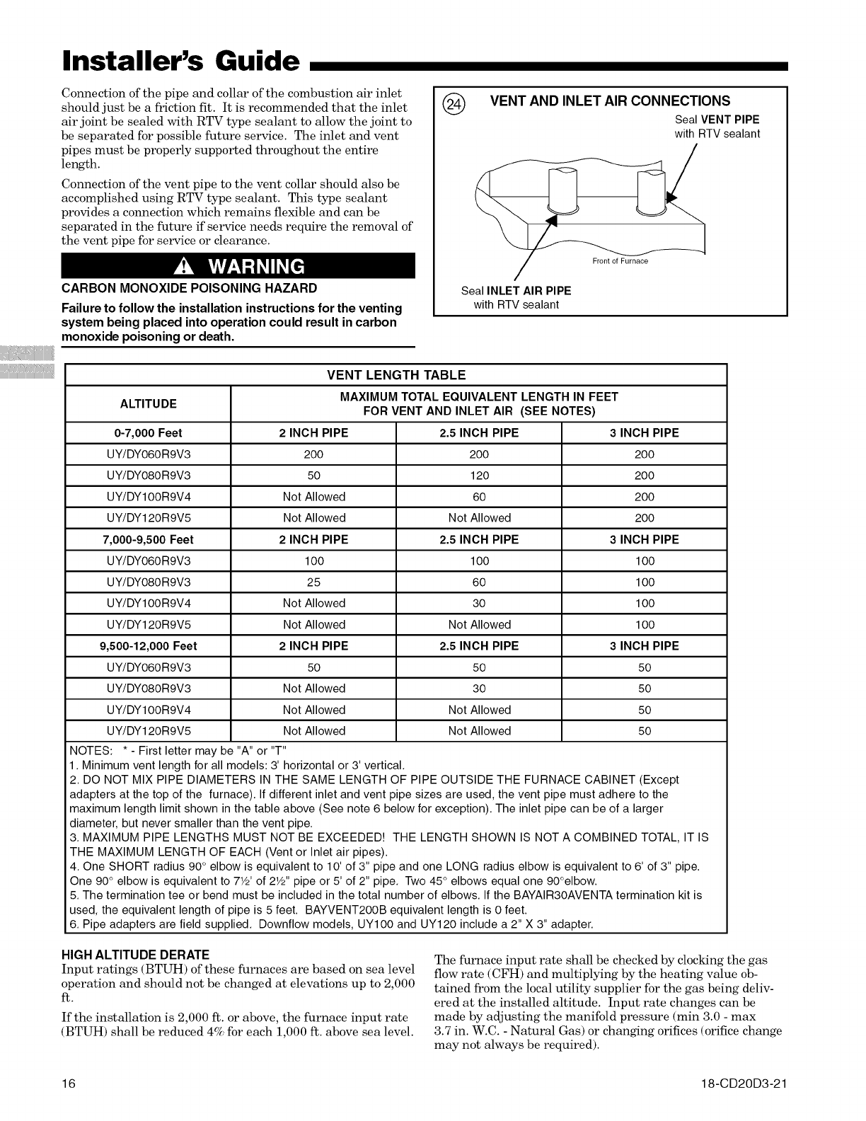
Connection of the pipe and collar of the combustion air inlet
should just be a friction fit. It is recommended that the inlet
air joint be sealed with RTV type sealant to allow the joint to
be separated for possible future service. The inlet and vent
pipes must be properly supported throughout the entire
length.
Connection of the vent pipe to the vent collar should also be
accomplished using RTV type sealant. This type sealant
provides a connection which remains flexible and can be
separated in the future if service needs require the removal of
the vent pipe for service or clearance.
CARBON MONOXIDE POISONING HAZARD
Failure to follow the installation instructions for the venting
system being placed into operation could result in carbon
monoxide poisoning or death.
@VENT AND INLET AIR CONNECTIONS
Seal VENT PIPE
with RTV sealant
Seal INLET AIR PIPE
with RTV sealant
Front of Furnace
VENT LENGTH TABLE
ALTITUDE MAXIMUM TOTAL EQUIVALENT LENGTH IN FEET
FOR VENT AND INLET AIR (SEE NOTES)
0-7,000 Feet 2 INCH PIPE 2.5 INCH PIPE 3 INCH PIPE
UY/DYO6OR9V3 200 200 200
UY/DYO8OR9V3 50 120 200
UY/DYIOOR9V4 Not Allowed 60 200
UY/DY120R9V5 Not Allowed Not Allowed 200
7,000-9,500 Feet 2 INCH PIPE 2.5 INCH PIPE 3 INCH PIPE
UY/DYO6OR9V3 1O0 1O0 1O0
UY/DYO8OR9V3 25 60 1O0
UY/DYIOOR9V4 Not Allowed 30 100
UY/DY120R9V5 Not Allowed Not Allowed 1O0
9,500-12,000 Feet 2 INCH PIPE 2.5 INCH PIPE 3 INCH PIPE
UY/DYO6OR9V3 50 50 50
UY/DYO8OR9V3 Not Allowed 30 50
UY/DYIOOR9V4 Not Allowed Not Allowed 50
UY/DY120R9V5 Not Allowed Not Allowed 50
NOTES: * - First letter may be "A" or "T"
1. Minimum vent length for all models: 3' horizontal or 3' vertical.
2. DO NOT MIX PIPE DIAMETERS IN THE SAME LENGTH OF PIPE OUTSIDE THE FURNACE CABINET (Except
adapters at the top of the furnace). If different inlet and vent pipe sizes are used, the vent pipe must adhere to the
maximum length limit shown in the table above (See note 6 below for exception). The inlet pipe can be of a larger
diameter, but never smaller than the vent pipe.
3. MAXIMUM PIPE LENGTHS MUST NOT BE EXCEEDED! THE LENGTH SHOWN IS NOT A COMBINED TOTAL, IT IS
THE MAXIMUM LENGTH OF EACH (Vent or Inlet air pipes).
4. One SHORT radius 90 ° elbow is equivalent to 10' of 3" pipe and one LONG radius elbow is equivalent to 6' of 3" pipe.
One 90 ° elbow is equivalent to 71/2' of 21/2'' pipe or 5' of 2" pipe. Two 45° elbows equal one 90°elbow.
5. The termination tee or bend must be included in the total number of elbows. If the BAYAIR3OAVENTA termination kit is
used, the equivalent length of pipe is 5 feet. BAYVENT2OOB equivalent length is 0 feet.
6. Pipe adapters are field supplied. Downflow models, UYIO0 and UY120 include a 2" X 3" adapter.
HIGH ALTITUDE DERATE
Input ratings (BTUH) of these furnaces are based on sea level
operation and should not be changed at elevations up to 2,000
ft.
If the installation is 2,000 ft. or above, the furnace input rate
(BTUH) shall be reduced 4% for each 1,000 ft. above sea level.
The furnace input rate shall be checked by clocldng the gas
flow rate (CFH) and multiplying by the heating value ob-
tained from the local utility supplier for the gas being deliv-
ered at the installed altitude. Input rate changes can be
made by adjusting the manifold pressure (min 3.0 - max
3.7 in. W.C. - Natural Gas) or changing orifices (orifice change
may not always be required).
16 18-CD20D3-21
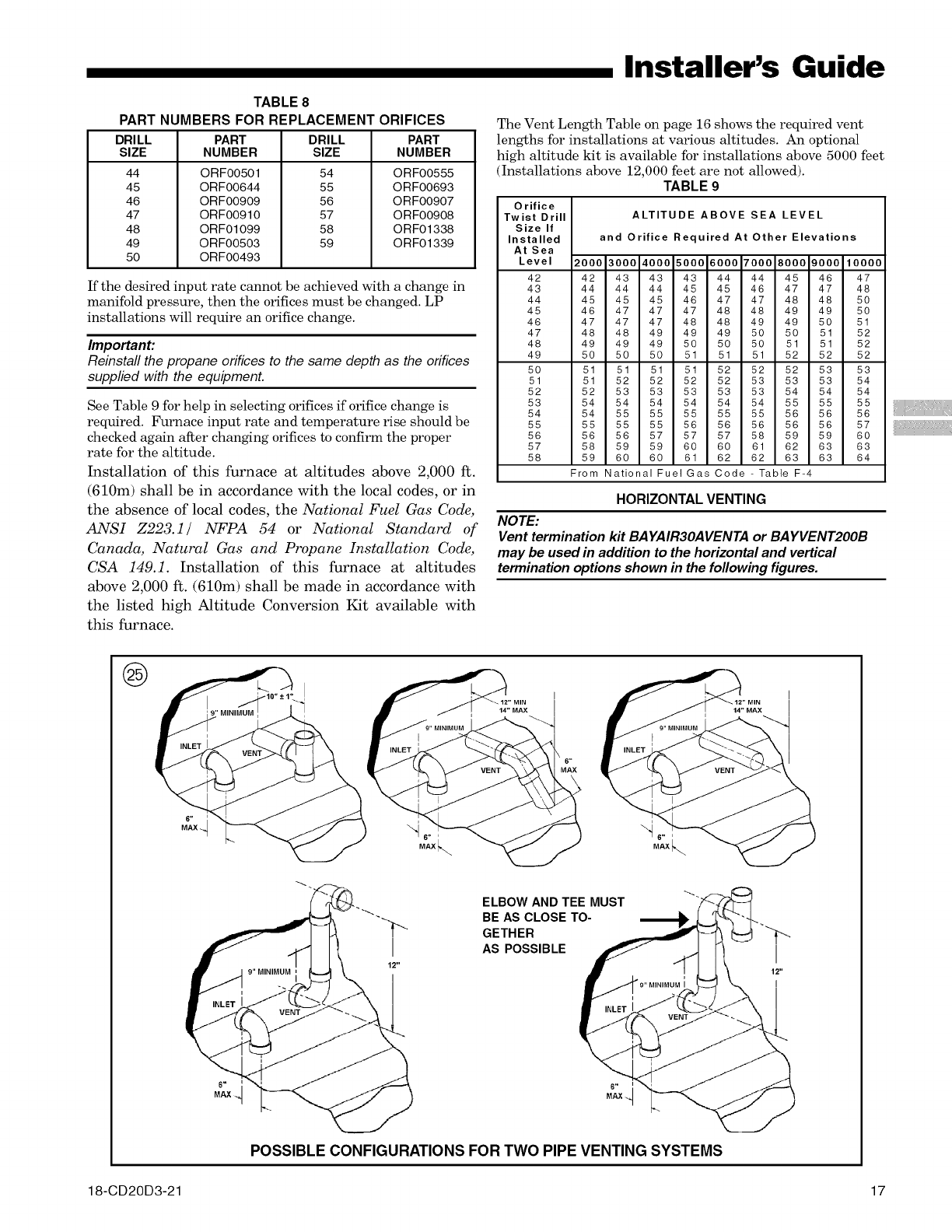
TABLE8
PART NUMBERS FOR REPLACEMENT ORIFICES
DRILL DRILL
SIZE SIZE
44
45
46
47
48
49
50
PART
NUMBER
ORF00501
ORF00644
ORF00909
ORF00910
ORF01099
ORF00503
ORF00493
54
55
56
57
58
59
PART
NUMBER
ORF00555
ORF00693
ORF00907
ORF00908
ORF01338
ORF01339
If the desired input rate cannot be achieved with a change in
manifold pressure, then the orifices must be changed. LP
installations will require an orifice change.
Important:
Reinstafl the propane orifices to the same depth as the orifices
supplied with the equipment.
See Table 9 for help in selecting orifices if orifice change is
required. Furnace input rate and temperature rise should be
checked again after changing orifices to confirm the proper
rate for the altitude.
Installation of this furnace at altitudes above 2,000 ft.
(610m) shall be in accordance with the local codes, or in
the absence of local codes, the National Fuel Gas Code,
ANSI Z223.1/ NFPA 54 or National Standard of
Canada, Natural Gas and Propane Installation Code,
CSA 149.1. Installation of this furnace at altitudes
above 2,000 ft. (610m) shall be made in accordance with
the listed high Altitude Conversion Kit available with
this furnace.
Installer's Guide
The Vent Length Table on page 16 shows the required vent
lengths for installations at various altitudes. An optional
high altitude kit is available for installations above 5000 feet
(Installations above 12,000 feet are not allowed).
TABLE 9
Orifice
Twist Drill
Size If
Installed
At Sea
Level
42
43
44
45
46
47
48
49
50
51
52
53
54
55
56
57
58
ALTITUDE ABOVE SEA LEVEL
and Orifice Required At Other Elevations
2000 3000 4000 5000 6000 7000 8000 9000 10000
42 43 43 43 44 44 45 46 47
44 44 44 45 45 46 47 47 48
45 45 45 46 47 47 48 48 50
46 47 47 47 48 48 49 49 50
47 47 47 48 48 49 49 50 51
48 48 49 49 49 50 50 51 52
49 49 49 50 50 50 51 51 52
50 50 50 51 51 51 52 52 52
51 51 51 51 52 52 52 53 53
51 52 52 52 52 53 53 53 54
52 53 53 53 53 53 54 54 54
54 54 54 54 54 54 55 55 55
54 55 55 55 55 55 56 56 56
55 55 55 56 56 56 56 56 57
56 56 57 57 57 58 59 59 60
58 59 59 60 60 61 62 63 63
59 60 60 61 62 62 63 63 64
From National FuelGas Code- Table F-4
HORIZONTAL VENTING
NOTE:
Vent termination kit BA YAIR3OAVENTA or BA YVENT2OOB
may be used in addition to the horizontal and vertical
termination options shown in the following figures.
®
ELBOW AND TEE MUST
BE AS CLOSE TO-
GETHER
AS POSSIBLE
POSSIBLE CONFIGURATIONS FOR TWO PIPE VENTING SYSTEMS
18-CD20D3-21 17
Installer's Guide
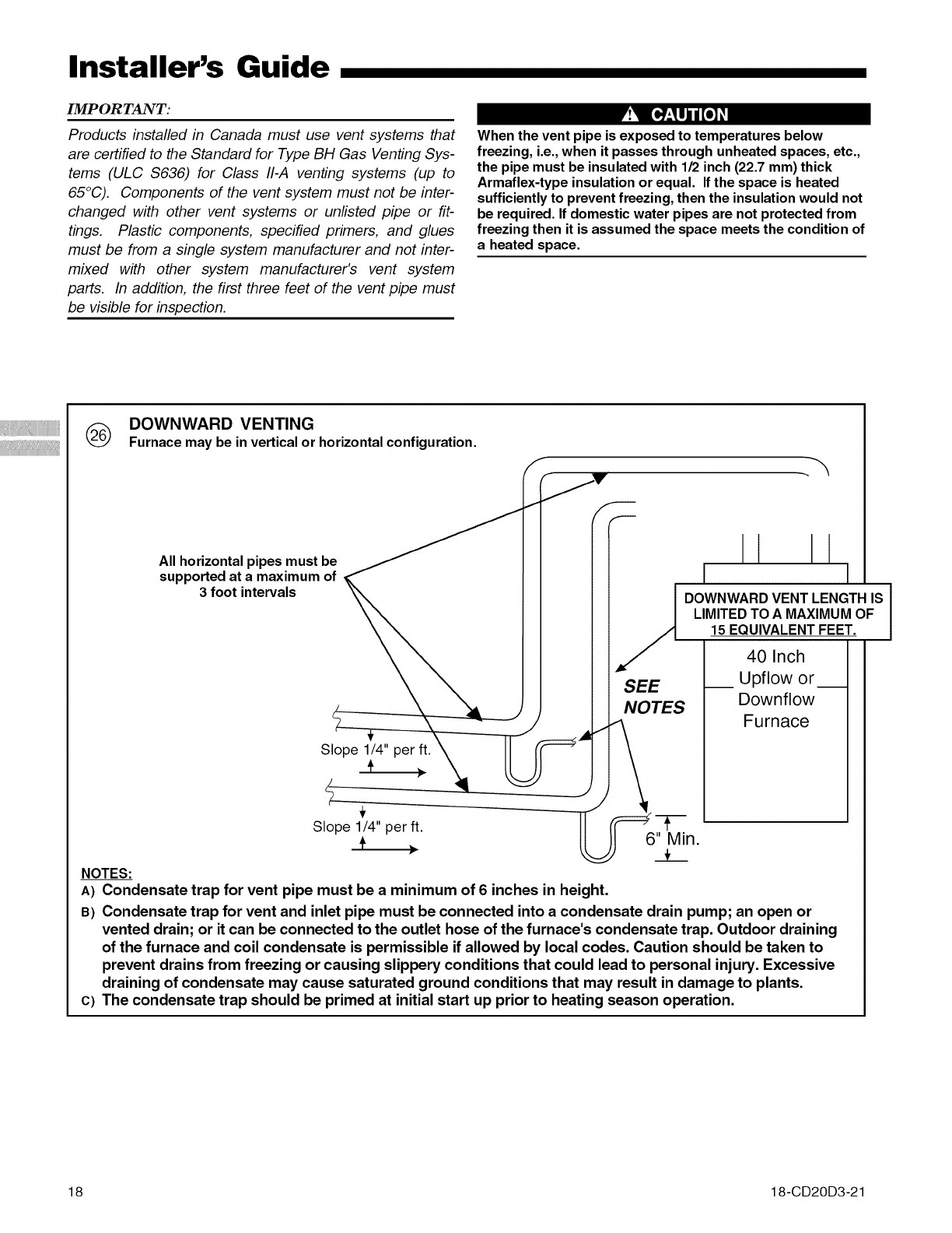
IMP OR TANT: r!_ :e_lj_o] _I
Products installed in Canada must use vent systems that
are certified to the Standard for Type BH Gas Venting Sys-
tems (ULC $636) for Class 11-,4venting systems (up to
65°C). Components of the vent system must not be inter-
changed with other vent systems or unlisted pipe or fit-
tings. Plastic components, specified primers, and glues
must be from a single system manufacturer and not inter-
mixed with other system manufacturer's vent system
parts. In addition, the first three feet of the vent pipe must
be visible for inspection.
When the vent pipe is exposed to temperatures below
freezing, i.e., when it passes through unheated spaces, etc.,
the pipe must be insulated with 112inch (22.7 mm) thick
Armaflex-type insulation or equal. If the space is heated
sufficiently to prevent freezing, then the insulation would not
be required. If domestic water pipes are not protected from
freezing then it is assumed the space meets the condition of
a heated space.
(_ DOWNWARD VENTING
Furnacemaybe in verticalor horizontalconfiguration.
All horizontal pipes must be
supported at a maximum of
3foot intervals
Slope 1/4" per ft.
Slope 1/4" per ft.
÷ ,
f
1I|
DOWNWARDVENT LENGTHIS I
LIMITEDTO A MAXIMUMOF I15 EQUIVALENTFEET.
SEE
NOTES
40 Inch
__ Upflow or__
Downflow
Furnace
-F
6" Min.
__t_
NOTES:
A) Condensate trap for vent pipe must be a minimum of 6 inches in height.
B) Condensate trap for vent and inlet pipe must be connected into a condensate drain pump; an open or
vented drain; or it can be connected to the outlet hose of the furnace's condensate trap. Outdoor draining
of the furnace and coil condensate is permissible if allowed by local codes. Caution should be taken to
prevent drains from freezing or causing slippery conditions that could lead to personal injury. Excessive
draining of condensate may cause saturated ground conditions that may result in damage to plants.
c) The condensate trap should be primed at initial start up prior to heating season operation.
18 18-CD20D3-21
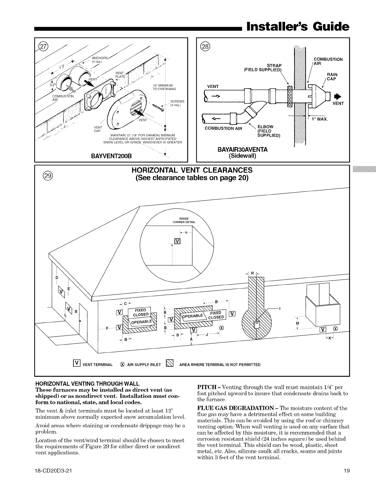
Installer's Guide
@
12" MINIMUM
TO OVERHANG
/
VENT
CAP
MAINTAIN 12" (18' FOR CANADA) MINIMUM
CLEARANCE ABOVE HIGHEST ANTICIPATED
SNOW LEVEL OR GRADE WHICHEVER IS GREATER
BAYVENT2OOB "'.
@
STRAP
(FIELD SUPPLIED L
VENT
o
COMBUSTION AIR (FIELD
SUPPLIED)
BAYAIR30AVENTA
(Sidewall)
COMBUSTION
AIR
N
HORIZONTAL VENT CLEARANCES
(See clearance tables on page 20)
INSIDE
CORNER DETAIL
i+G
["_ VENTTERMINAL (_) AIR SUPPLY INLET E_ AREAWHERETERMINAL IS NOT PERMITTED
HORIZONTAL VENTING THROUGH WALL
These furnaces may be installed as direct vent (as
shipped) or as nondirect vent. Installation must con-
form to national, state, and local codes.
The vent & inlet terminals must he located at least 12"
minimum above normally expected snow accumulation level.
Avoid areas where staining or condensate drippage may be a
problem.
Location of the vent/wind terminal should be chosen to meet
the requirements of Figure 29 for either direct or nondirect
vent applications.
PITCH -Venting through the wall must maintain 1/4" per
foot pitched upward to insure that condensate drains back to
the furnace.
FLI_ GAS DEGRADATION - The moisture content of the
flue gas may have a detrimental effect on some building
materials. This can be avoided by using the roof or chimney
venting option. When wall venting is used on any surface that
can be affected by this moisture, it is recommended that a
corrosion resistant shield (24 inches square) be used behind
the vent terminal. This shield can be wood, plastic, sheet
metal, etc. Also, silicone caulk all cracks, seams and joints
within 3 feet of the vent terminal.
18-CD20D3-21 19
Installer's Guide
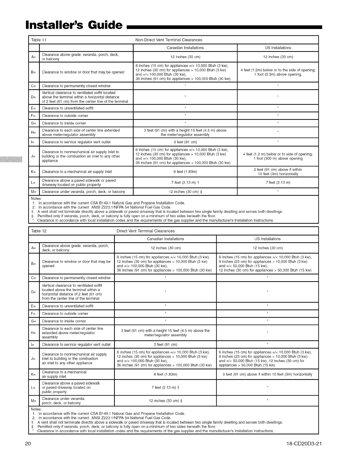
Table 11 Non-Direct Vent Terminal Clearances
Canadian Installations US Installations
Clearance above grade, veranda, porch, deck,
A= or balcony 12 inches (30 cm) 12 inches (30 cm)
6 inches (15 cm) for appliances =/< 10,000 Btuh (3 kw),
B= Clearance to window or door that may be opened 12 inches (30 cm) for appliances > 10,000 Btuh (3 kw) 4 feet (1.2m) below or to the side of opening;
and =/< 100,000 Btuh (30 kw), 1 foot (0.3m) above opening.
36 inches (91 cm) for appliances > 100,000 Btuh (30 kw)
C= Clearance to permanently closed window
Vertical clearance to ventilated soffit located
D= above the terminal within a horizontal distance
of 2 feet (61 cm) from the center line ef the terminal
E= Clearance to unventilated soffit
F= Clearance to outside corner
G= Clearance to inside corner
Clearance to each side of center line extended 3 feet (91 cm) with a height 15 feet (4.5 m) above
H= above meter/regulator assembly the meter/regulator assembly
I= Clearance to service regulator vent outlet 3 feet (91 cm)
Clearance to nenmechanical air supply inlet to 6 inches (15 cm) fer appliances =/< 10,000 Btuh (3 kw),
12 inches (30 cm) for appliances > 10,000 Btuh (3 kw) 4 feet (1.2 m) below or to side of opening;
J= building or the combustion air inlet to any other and =/< 100,000 Btuh (30 kw), 1 foot (300 m) above opening
appliance 36 inches (91 cm) for appliances > 100,000 Btuh (30 kw)
K= Clearance to a mechanical air supply inlet 6 feet (1.83m) 3 feet (91 cm) above if within
10 feet (3m) horizontally
L= Clearance above a paved sidewalk or paved
driveway located on public property 7 feet (2.13 m) 1- 7 feet (2.13 m)
M= Clearance under veranda, porch, deck, or balcony 12 inches (30 cm) :l:
Notes:
1. In accordance with the current CSA B149.1 Natural Gas and Propane Installation Code.
2. In accordance with the current ANSI Z223.1/NFPA 54 National Fuel Gas Code.
1-. A vent shall not terminate directly above a sidewalk or paved driveway that is located between two single family dwelling and serves both dwellings.
:l:. Pemitted only if veranda, porch, deck, or balcony is fully open on a minimum of two sides beneath the floor.
* Clearance in accordance with local installation codes and the requirements of the gas supplier and the manufacturer's Installation Instructions.
Table 12 Direct Vent Terminal Clearances
Canadian Installations US Installations
Clearance above grade, veranda, porch,
A= deck, or balcony 12 inches (30 cm) 12 inches (30 cm)
6 inches (15 cm) for appliances =/< 10,000 Btuh (3 kw), 6 inches (15 cm) for appliances =/< 10,000 Btuh (3 kw),
B= Clearance to window or door that may be 12 inches (30 cm) for appliances > 10,000 Btuh (3 kw) 9 inches (23 cm) for appliances > 10,000 Btuh (3 kw)
opened and =/< 100,000 Btuh (30 kw), and =/< 50,000 Btuh (15 kw),
36 inches (91 cm) for appliances > 100,000 Btuh (30 kw) 12 inches (30 cm) for appliances > 50,000 Btuh (15 kw)
C= Clearance to permanently closed window
Vertical clearance to ventilated soffit
located above the terminal within a
D= horizontal distance of 2 feet (61 cm)
from the center line of the terminal
E= Clearance to unventilated soffit
F= Clearance to outside corner
G= Clearance to inside corner
Clearance to each side of center line
H= extended above meter/regulator 3 feet (91 cm) with a height 15 feet (4.5 m) above the
assembly meter/regulator assembly
I= Clearance to service regulator vent outlet 3 feet (91 cm)
Clearance to nenmechanical air supply 6 inches (15 cm) for appliances =/< 10,000 Btuh (3 kw), 6 inches (15 cm) for appliances =/< 10,000 Btuh (3 kw),
12 inches (30 cm) for appliances > 10,000 Btuh (3 kw) 9 inches (23 cm) for appliances > 10,000 Btuh (3 kw)
J= inlet to building or the combustion and =/< 100,000 Btuh (30 kw), and =/< 50,000 Btuh (15 kw), 12 inches (30 cm) for
air inlet to any other appliance 36 inches (91 cm) for appliances > 100,000 Btuh (30 kw) appliances > 50,000 Btuh (15 kw)
Clearance to a mechanical
K= air supply inlet 6 feet (1.83m) 3 feet (91 cm) above if within 10 feet (3m) horizontally
Clearance above a paved sidewalk
L= or paved driveway located on 7 feet (2.13 m) 1-
public property
M= Clearance under veranda, 12 inches (30 cm) :l:
porch, deck, or balcony
Notes:
1. In accordance with the current CSA B149.1 Natural Gas and Propane Installation Code.
2. In accordance with the current ANSI Z223.1/NFPA 54 National Fuel Gas Code.
1-. A vent shall not terminate directly above a sidewalk or paved driveway that is located between two single family dwelling and serves both dwellings.
:l:. Pemitted only if veranda, porch, deck, or balcony is fully open on a minimum of two sides beneath the floor.
* Clearance in accordance with local installation codes and the requirements of the gas supplier and the manufacturer's Installation Instructions.
20 18-CD20D3-21
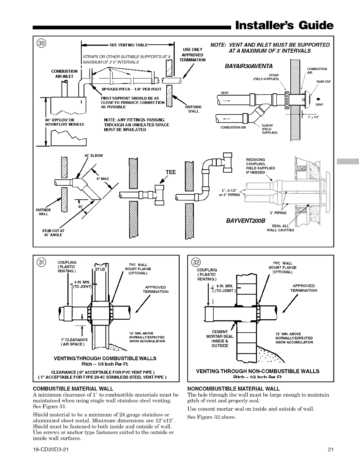
®
COMBUSTION
AIR INLET
Nf
T/ J
40" UPFLOW OR
DOWN FLOW/,_ODE LS
OUTSIDE
WALL
STUB CUT AT
45 °ANGLE
Installer's Guide
SEE VENT ING TABLE ,_-
USE ONLY
STRAPS OR OTHER SUITABLE SUPPORTS AT A APPROVED
MAXIMUM OF 3' 0" INTERVALS P"'I TERMINATION
RRST SUPPORT SHOULD BE T
CLOSETO RIRNACE CONNECTION
AS POS:_IBLE OUTSIDE
WALL
NOTE: ANY FI1-BN,GS PASSING
THROUGH AN UNHEATED SPACE
MUST BE INSULATED
NOTE: VENT AND INLET MUST BE SUPPORTED
AT A MAXIMUM OF 3' INTERVALS
BAYAIR3OAVENTA [_ COMBUSTION
STRAP I_/
(FIELD SUPPLIED) _RAIN CAP
VENT /
.- ILF HI, ,.._.,,2..
CONBUST,ONA,R"_
SUPPLIED)
45° ELBOW
t/" .-I_I_L# ICOUPLING _i_'_;:_
L.J[ -- H FIELD SUPPLIED ;;_:":'_!_
TEE I,__,I I I IF NEEDED !i[......(:itS!":':_
.-, (( (
I_ 2% 2-1/2" _ ....................................................I_--. i.....................................................................
hIIII _ I _ Jor 3" PIPING "_; ",_'_=_? .......
3" PIPING 1[_ ::"._;_,_:
SEAL ALL /_1_ _ J
WALL CAVITIES
®COUPLING
( PLASTIC
VENTING
IN. MIP
(:)JOIN
-[
1" CLEARANCE
( AIR SPACE )
DVC WALL
MOUNT FLANGE
[OPTIONAL)
APPROVED
TERMINATION
12" MIN. ABOVE
NORMALLY EXPECTED
_,NOW ACCUMULATION
VENTINGTHROUGH COMBUSTIBLEWALLS
Pitch-- 1/4Inch PerFt.
CLEARANCE ( 0" ACCEPTABLE FOR PVC VENT PIPE )
( 1" ACCEPTABLE FOR TYPE 29-4C STAINLESS STEEL VENT PIPE )
COMBUSTIBLE MATERIAL WALL
A minimum clearance of i" to combustible materials must be
maintained when using single wall stainless steel venting.
See Figure 31.
Shield material to be a minimum of 24 gauge stainless or
aluminized sheet metal. Minimum dimensions are 12"x12".
Shield must be fastened to both inside and outside of wall.
Use screws or anchor type fasteners suited to the outside or
inside wall surfaces.
®
COUPLIN G
(PLASTIC
VENTING )
14 6IN,MIN.
III(ToJolNT
]
M OCRET_ENTAL_-_
INSIDE &
OUTSIDE
PVC WALL
MOUNT FLANGE
[OPTIONAL)
APPROVED
TERMINATION
12" MIN. ABOVE
NORMALLY EXPECTED
SNOW ACCUMULATION
VENTING THROUGH NON-COMBUSTIBLE WALLS
I_fPh - 1/.4 Inrh ID_r Ff
NONCOMBUSTIBLE MATERIAL WALL
The hole through the wall must be large enough to maintain
pitch of vent and properly seal.
Use cement mortar seal on inside and outside of wall.
See Figure 32 above.
18-CD20D3-21 21
iiiiiiiiiiii
Installer's Guide
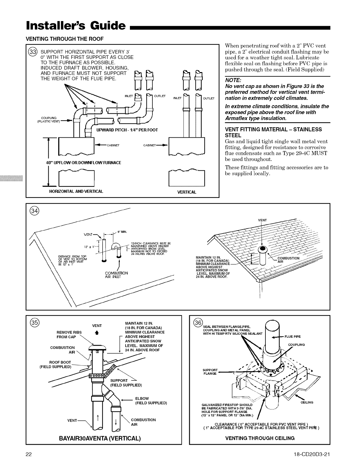
VENTING THROUGH THE ROOF
SUPPORT HORIZONTAL PIPE EVERY 3'
0" WITH THE FIRST SUPPORT AS CLOSE
TO THE FURNACE AS POSSIBLE.
INDUCED DRAFT BLOWER, HOUSING,
FurnaCE OTSU O TD
THE WEIGHTOF THE FLUE PIPE.
°' //
40" UPFLOW OR DOWNFLOW FURNACE
HORIZONTAL AND VERTICAL VERTICAL
!UTLET
When penetrating roof with a 2" PVC vent
pipe, a 2" electrical conduit flashing may be
used for a weather tight seal. Lubricate
flexible seal on flashing before PVC pipe is
pushed through the seal. (Field Supplied)
NOTE:
No vent cap as shown in Figure 33 is the
preferred method for vertical vent termi-
nation in extremely cold climates.
In extreme climate conditions, insulate the
exposed pipe above the roof line with
Armaflex type insulation.
VENT FITTING MATERIAL- STAINLESS
STEEL
Gas and liquid tight single wall metal vent
fitting, designed for resistance to corrosive
flue condensate such as Type 29-4C MUST
be used throughout.
These fittings and fitting accessories are to
be supplied locally.
®
9" MIN.
VENT_'_ .L-_.I_'_/- "'""" 12-INCH CLEAr4ANCE MUST BE
]2' ± ],_1_ MAINTAINED ABOVE HIGHEST
AN'nC1PA]ED SNOW LEVEL
MAXIMUM NOT TO EXCEED
24 INCHES ABOVE ROOF,
D,STANCE FROM TOP _
OF VENT TO BOSOM
OF AIR INLET MUST
BE 12' ± 1' )
/
COMBUSTION
AIR INLET
MAINTAIN 12 IN.
ABOVE HIGHEST
ANTICIPATED SNOW
LEVEL. MAXIMUM OF
24 IN. ABOVE ROOF.
VENT
®
REMOVE RIBS
FROM CAP
COMBUSTION
AIR
ROOF BOOT
MAINTAIN 12 IN.
VENT (18 IN. FOR CANADA)
_i" MINIMUM CLEARANCE
IBOVE HIGHEST
ANTICIPATED SNOW
LEVEL. MAXIMUM OF
24 IN. ABOVE ROOF
suP
(FIELD SUPPLIED)
ELBOW
(FIELD SUPPLIED)
VENT-_
COMBUSTION
AIR
BAYAIR30AVENTA (VERTICAL)
_SEAL BETWEEN FLANGE,PIPE,
COUPLING AND METAL PANEL
WITH HI TEMP RTV SILICONE SEALANT
COUPLING
SUPPORT
FLANGE
CEILING
GALVANIZED FIRESTOP SHOULD
BE FABRICATED WITH 3-7/8" DIA.
HOLE FOR SUPPORT FLANGE
(12" X12" PANEL OR 12" DIA MIN,) ,_
CLEARANCE {0" ACCEPTABLE FOR PVC VENT PIPE)
( 1" ACCEPTABLE FOR TYPE 29-4C STAINLESS STEEL VENT PII::_E )
VENTING THROUGH CEILING
22 18-CD20D3-21
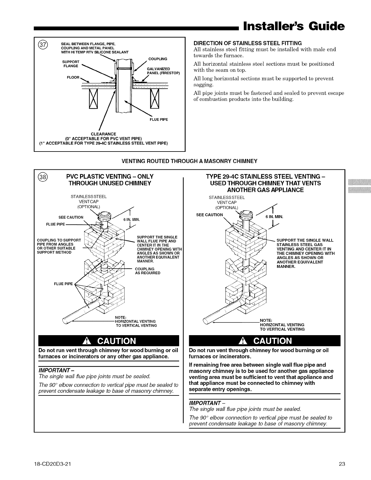
®SEAL BETWEEN FLANGE, PIPE,
COUPLING AND METAL PANEL
WITH HI TEMP RTV SILICONE SEALANT
SUPPORT _
Installer's Guide
FLANGE _
FLOOR
COUPLING
GALVANIZED
PANEL (FIRESTOP)
FLUE PIPE
CLEARANCE
(0" ACCEPTABLE FOR PVC VENT PIPE)
(1" ACCEPTABLE FOR TYPE 29-4C STAINLESS STEEL VENT PIPE)
DIRECTION OF STAINLESS STEEL FITTING
All stainless steel fitting must be installed with male end
towards the furnace.
All horizontal stainless steel sections must be positioned
with the seam on top.
All long horizontal sections must be supported to prevent
sagging.
All pipe joints must be fastened and sealed to prevent escape
of combustion products into the building.
VENTING ROUTED THROUGH A MASONRY CHIMNEY
®PVC PLASTIC VENTING - ONLY
THROUGH UNUSED CHIMNEY
STAINLESSSTEEL
VENTCAP
(OPTIONAL) //
SEE CAUTION. _ _6 IN. MIN.
FLUE PIPE _ _j.
"_'_/I SUPPORT THE SINGLE
COUPLING TO SUPPORT ._ .#-._7_.........._ WALL FLUE PIPE AND
PIPE FROM ANGLES _L..._ "-b_.j//zp _iF) CENTER IT IN THE
OR OTHER SUITABLE "--_."'_._ "_/_, _CHIMNEY OPENING WITH
suPPORTMETHOD \_/ ANGLESASSHOWNOR
"">._1 ._ ANOTHER EQUIVALENT
-__ COUPLING
;_<"_/_S_ AS REQUIRED
FLUE PIPE
_NOTE:
•HORIZONTAL VENTING
TO VERTICAL VENTING
Do not run vent through chimney for wood burning or oil
furnaces or incinerators or any other gas appliance.
IMPORTANT-
The single wall flue pipe joints must be sealed.
The 90°elbow connection to vertical pipe must be sealed to
prevent condensate leakage to base of masonry chimney.
TYPE 29-4C STAINLESS STEEL VENTING -
USED THROUGH CHIMNEY THAT VENTS
ANOTHER GAS APPLIANCE
STAINLESS STEEL
VENTCAP
(OPTIONAL)
SEE CAUTION 6 IN. MIN.
SUPPORT THE SINGLE WALL
STAINLESS STEEL GAS
VENTING AND CENTER IT IN
THE CHIMNEY OPENING WITH
ANGLES AS SHOWN OR
ANOTHER EQUIVALENT
MANNER.
NOTE:
HORIZONTAL VENTING
TO VERTICAL VENTING
Do not run vent through chimney for wood burning or oil
furnaces or incinerators.
If remaining free area between single wall flue pipe and
masonry chimney is to be used for another gas appliance
venting area must be sufficient to vent that appliance and
that appliance must be connected to chimney with
separate entry openings.
IMPORTANT-
The single wall flue pipe joints must be sealed.
The 90° elbow connection to vertical pipe must be sealed to
prevent condensate leakage to base of masonry chimney.
18-CD20D3-21 23
Installer's Guide
IMPORTANT:
The Commonwealth of Massachusetts requires compliance
with regulation 248 CMR 4.00 and 5.00 for installation of
through - the - wall vented gas appliances as follows:
For all side wall horizontally vented gas fueled equipment
installed in every dwelling, building or structure used in
whole or in part for residential purposes, including those
owned or operated by the Commonwealth and where the
side wall exhaust vent termination is less than seven (7)
feet above finished grade in the area of the venting,
including but not limited to decks and porches, the
following requirements shall be satisfied:
1. INSTALLATION OF CARBON MONOXIDE
DETECTORS. At the time of installation of the side wall
horizontal vented gas fueled equipment, the installing
plumber or gasfitter shall observe that a hard wired
carbon monoxide detector with an alarm and battery back-
up is installed on the floor level where the gas equipment
is to be installed. In addition, the installing plumber or
gasfitter shall observe that a battery operated or hard
wired carbon monoxide detector with an alarm is installed
on each additional level of the dwelling, building or
structure served by the side wall horizontal vented gas
fueled equipment. It shall be the responsibility of the
property owner to secure the services of qualified licensed
professionals for the installation of hard wired carbon
monoxide detectors
a. In the event that the side wall horizontally vented
gas fueled equipment is installed in a crawl space or an
attic, the hard wired carbon monoxide detector with alarm
and battery back-up may be installed on the next adjacent
floor level.
b. In the event that the requirements of this
subdivision can not be met at the time of completion of
installation, the owner shall have a period of thirty (30)
days to comply with the above requirements; provided,
however, that during said thirty (30) day period, a battery
operated carbon monoxide detector with an alarm shall be
installed.
2. APPROVED CARBON MONOXIDE
DETECTORS. Each carbon monoxide detector as required
in accordance with the above provisions shall comply with
NFPA 720 and be ANSI!UL 2034 listed and IAS certified.
3. SIGNAGE. A metal or plastic identification plate
shall be permanently mounted to the exterior of the
building at a minimum height of eight (8) feet above grade
directly in line with the exhaust vent terminal for the
horizontally vented gas fueled heating appliance or
equipment. The sign shall read, in print size no less than
one-half (1/2) inch in size, "GAS VENT DIRECTLY
BELOW. KEEP CLEAR OF ALL OBSTRUCTIONS".
4. INSPECTION. The state or local gas inspector of
the side wall horizontally vented gas fueled equipment
shall not approve the installation unless, upon inspection,
the inspector observes carbon monoxide detectors and
signage installed in accordance with the provisions of 248
CMR 5.08(2)(a)1 through 4.
This appliance requires a special venting system. If
BAYAIR30AVENTA or BAYVENT200B are used, a copy of
the installation instructions for the kit shall remain with
the appliance or equipment at the completion of
installation. The venting system installation instructions
can be obtained from the manufacturer by writing to the
following address:
American Standard, Inc.
6200 Troup Highway
Tyler, TX 75707
Attention: Manager of Field Operations Excellence
24 18-CD20D3-21
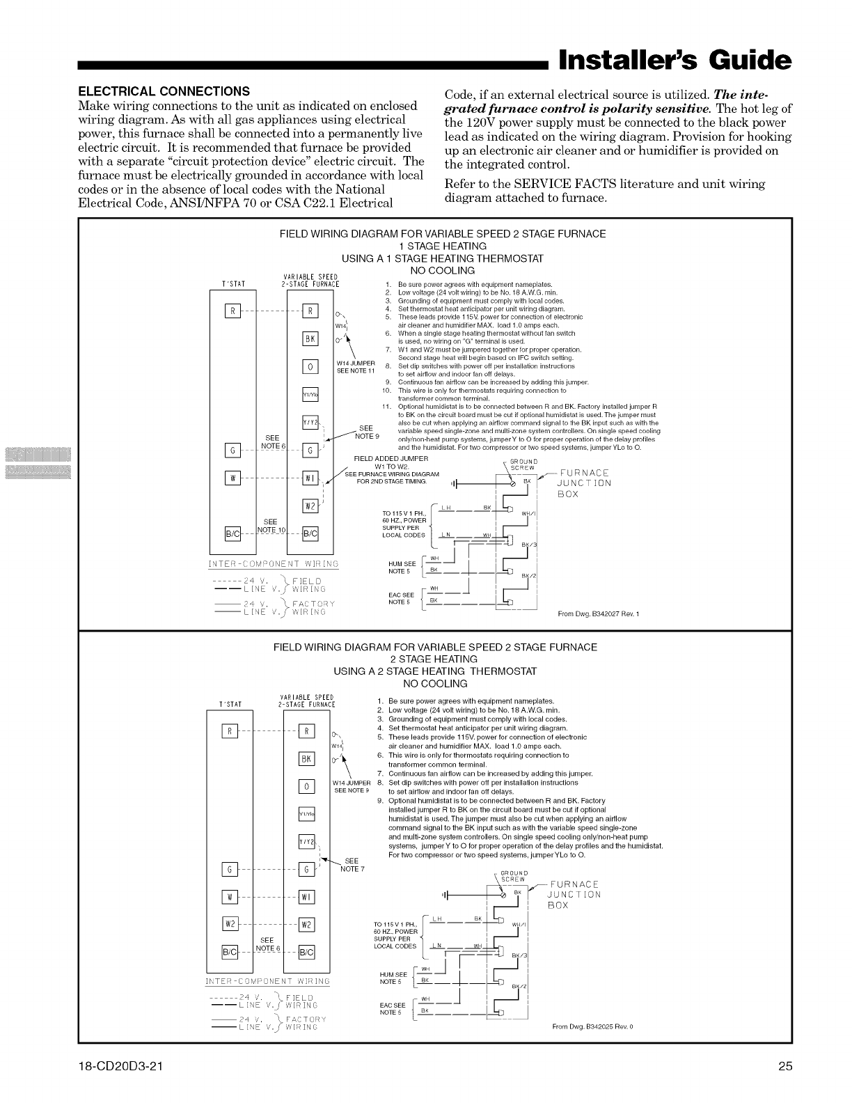
Installer's Guide
ELECTRICAL CONNECTIONS
Make wiring connections to the unit as indicated on enclosed
wiring diagram. As with all gas appliances using electrical
power, this furnace shah be connected into a permanently live
electric circuit. It is recommended that furnace be provided
with a separate "circuit protection device" electric circuit. The
furnace must be electrically grounded in accordance with local
codes or in the absence of local codes with the National
Electrical Code, ANSI!NFPA 70 or CSA C22.1 Electrical
Code, if an external electrical source is utilized. The inte-
grated furnace control is polarity sensitive. The hot leg of
the 120V power supply must be connected to the black power
lead as indicated on the wiring diagram. Provision for hooldng
up an electronic air cleaner and or humidifier is provided on
the integrated control.
Refer to the SERVICE FACTS literature and unit wiring
diagram attached to furnace.
T'STAT
[]
FIELD WIRING DIAGRAM FOR VARIABLE SPEED 2 STAGE FURNACE
1 STAGE HEATING
USING A 1 STAGE HEATING THERMOSTAT
NO COOLING
VARIABLE SPEED
2-STAGE FURNACE
[]
W141
] W14JUMPER
SEE NOTE 11
[]
[_'_ SEE
_NOTE9
SEE I_
1. Be sure power agrees with equipment nameplates.
2. Low voltage (24 volt wiring) to be No. 18 A.W.G. rain.
3. Grounding of equipment must comply with local codes.
4. Set thermostat heat anticipator per unit wiring diagram.
5. These leads provide 115M power for connection of electronic
air cleaner and humidifier MAX. load 1.0 amps each.
6. When a single stage heating thermostat without fan switch
is used, no wiring on "G" terminal is used.
7. Wl and W2 must be jumpered together for proper operation.
Second stage heat will begin based on IFC swNch setting.
8. Set dip switches with power off per installation instructions
to set airflow and indoor fan off delays.
9. Continuous fan airflow can be increased by adding this jumper.
10. This wire is only for thermostats requiring connection to
transformer common terminal.
11. Optional humidistat is to be connected between R and BK. Factory installed jumper R
to BK on the circuit board must be cut if optional humidistat is used. The jumper must
also be cut when applying an airflow command signal to the BK input such as with the
variable speed single-zone and mugi-zone system controllers. On single speed cooling
only/non-heat pump systems, jumper Y to O for proper operation of the delay profiles
]. J and the humidistat. For two compressor or two speed systems, jumper YLo to O.] NOTE 6
FIELD ADDED JUMPER GROU N D
Wl TOW2. SCREW
_. J_ _SEE FURNACE WIRING DIAGRAM [_'_ FUR NACE
L_J L_J ,, _ FOR 2ND STAGE TIMING. ,if _ _iK JUNCTION
:_I BOX
NOTE 10 SUPPLY PER I I
[] [] ........... N __. I
Y _[--_4J BI,31
I I WH I I
INTE7 )MPONENT WIRI ', ...... j- _"/I II I _ I
..... LBK--q#--I _ ....I
24 g. \FIELD II _ I
----LINE ,,/., _/ilR[NE F WH fl i _-I i
J EAC SEE
V. _ FAT'. RY ..... L BK _ ,
--L[qE ,., ,',,IK[No FromDwg. B342027Rev. 1
FIELD WIRING DIAGRAM FOR VARIABLE SPEED 2 STAGE FURNACE
2 STAGE HEATING
USING A 2 STAGE HEATING THERMOSTAT
NO COOLING
VARIABLE SPEED
2-STAGE FURRACE 1.
-- 2.
3.
4.
[] s.
[]
T "STAT
[]
[]
[]
_,,
[] ED'
[] []
[] []
SEE
[] NOTE []
II'TE:7 COvq;ONENT '?#]_]NG
P4 '/. !, FIELD
---- L INE /"S vYlR ING
..
2q Y'. t. F_ TDRY
-- L INE /,j" 'A' I! IN G
7.
W14JUMPER 8.
SEE NOTE9
9.
_SEE
NOTE 7
Be sure power agrees with equipment nameplates.
Low voltage (24 volt wiring) to be No. 18 A.W.G. rain.
Grounding of equipment must comply with local codes.
Set thermostat heat anticipator per unit wiring diagram.
These leads provide 115V. power for connection of electronic
air cleaner and humidifier MAX. load 1.0 amps each.
This wire is only for thermostats requiring connection to
transformer common terminal.
Continuous fan airflow can be increased by adding this jumper.
Set dip switches with power off per installation instructions
to set airflow and indoor fan off delays.
Optional humidistat is to be connected between R and BK. Factory
installed jumper R to BK on the circuit board must be cut if optional
humidistat is used. The jumper must also be cut when applying an airflow
command signal to the BK input such as with the variable speed single-zone
and multi-zone system controllers. On single speed cooling only/non-heat pump
systems, jumper Y to O for proper operation of the delay profiles and the humidistat.
For two compressor or two speed systems, jumperYLo to O.
From Dwg. B342025 Rev. 0
18-CD20D3-21 25
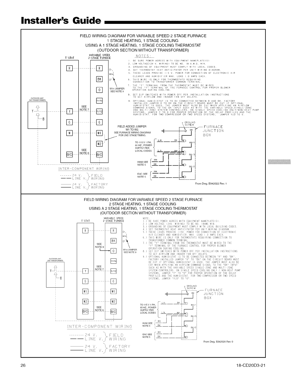
Installer's Guide
OUTDOOR UNiT
(NOTRANSFORMER}
FIELD WIRING DIAGRAM FOR VARIABLE SPEED 2 STAGE FURNACE
1 STAGE HEATING, 1 STAGE COOLING
USING A 1 STAGE HEATING, 1 STAGE COOLING THERMOSTAT
(OUTDOOR SECTION WITHOUT TRANSFORMER)
VARIABLE SPEED NOTES:
T'STAT 2-STAGE FURNACE
I BE S RE POWER AGREES WITH EQUIPMENT NAMEPLATE(S)
2. LOW VOLTAGE(Z4 v WIRING) TO BE NO 18 A W G. MIN
D _ 3 GROUNDING OF EQUIPMENT M ST COMPLY WITH LOCAL CODES
l_2_J 0_\ 4 SET THERMOSTAT HEAT ANTICIPATOR PER UNIT WIRING DIAGRAM
W14! S THESE LEADS PROVIDE 115 v POWER FOR CONNECTION OF ELECTRONIC AIR
/CLEANER AND HUMIDIFIER MAX LOAD I O AMPS EACH
r_ 6 THIS WIRE IS ONLY FOR THERMOSTATS REQUIRING
CO NECTION TO TRANSFORMER COMMON TERMINAL
7 THE "Y" TERMINAL FROM THE THERMOSTAT MUST BE WIRED
D W14JUMPER TO THE "Y" TERMINAL OF THE FURNACE CONTROL FOR PROPER BLOWER
OPERATION DINING COOLING
SEE NOTE 9
8 SET DIP SWITCHES WITH POWER OFF PER INSTALLATION INSTRUCTIONS
TO SET AIRFLOW AND INDOOR FAN OFF DELAYS
D 9 OPTIONAL HUMIDISTAT IS TO BE CONNECTED BETWEEN R AND BK. FACTORY
INSTALLED J£TPER R TO BK ON THE CIRCUIT BOARD MUST BE CUT IF OPTIONAL
SEE HUMIDISTAT IS USED THE JUMPER MUST ALSO BE CUT WHEN APPLYING AN AIRFLOW
COMMAND SIGNAL TO THE BH INP T S CH AS WITH THE VARIABLE SPEED,SINGLE ZONE
D NOTE7 _ AND MULTI ZONE SYSTEM CONTROLLERS, ON SINGLE SPEED COOLING ONLY/NON HEAT PUMP
I":_1 SYSTEMS JUMPER Y TO 0 FOR PROPER OPERATION OF THE DELAY PROFILES A O THE
HUMIDISTAT FOR TWO COMPRESSOR OR TWO SPEED SYSTEMS, JUMPER YLO TO 0
D D FIELD ADDED JUMPER _Cs_-_}_ .Z_ F U R N ACE
W1 TO W2. iBK ....
_ SEEFURNACEWIRINGDIAGRAM II I_ Be [" JUNCTION
L__[J ,1 FOR 2ND STAGE TIMING. Ii _ II BOX
jLH BK
TO 115V 1PH., [-- .... _ ..... I
BoHZ,POVVER! ,I_ ,
SUPPLY PER J I
SEE LOCALCODES 1 LN --I..._S I
B B LFr -=F 4J Tq
I WH / I I
I HUMSEE J_ wH "_ I II I'll II
•NOTE5 I BK--4 _I
INTER COMPONENT WIRING '- I - a_/21
WH I I
2 EAC SEE -- -- J
----LINE V._W[RING ° L I'_--_
24 v. _\ FACTORY FromDwg. B342022Rev. 1
--LINE V._'_ W[ _ IN G
OUTDOOR UNIT
(NOTRANSFOnMEn)
F
FIELD WIRING DIAGRAM FOR VARIABLE SPEED 2 STAGE FURNACE
2 STAGE HEATING, 1 STAGE COOLING
USING A 2 STAGE HEATING, 1 STAGE COOLING THERMOSTAT
(OUTDOOR SECTION WITHOUT TRANSFORM ER)
T'STAT
[]
VARIABLE SPEED
2-STAGE FURNACE
] 0-\
W14/i
[]
SEE
NOTE 9
L--_F]
[]
SEE
NO E7[]
[] []
[] []
[] []
SEE
[] NOTE°
i
L J
W14 JUMPER
SEE NOTE 9
NOTE:
I BE SURE POWER AGREES WITH EQUIPMENT NAMEPLATE(S)
2 LOW VOLTAGE [24V WIRING) TO BE NO IBAWGMIN
S GROUNDINGOF EQUIPMENTMUST COMPLY WITH LOCAL BUILDING CODES
4 SET THERMOSTATHEAT ANTICIPATOR PER UNIT WIRING DIAGRAM
5 THESE LEADS PROVIDE 115V POWERFOR CONNECTIONOF ELECTRONIC
AIR CLEANER AND HUMIDIFIER MAX LOAD IO AMPS EACH
6 THIS WIRE IS ONLY FOR THERMOSTATSREQUIRING CONNECTIONTO
TRANSFORMERCOMMONTERMINAL
7 THE IIyIITERMINAL FROM THE THERMOSTAT MUST BE WIRED TO THE
IIyII TERMINAL OF THE FURNACECONTROLFOR PROPER BLOWER
OPERATION DURING COOLING
8 SET DIP SWITCHES WITH POWEROFF PER INSTALLATION INSTRUCTIONS
TO SET AIRFLOW AND INDOORFAN OFF DELAYS
9 OPTIONAL HUMIDISTAT IS TO BE CONNECTEDBETWEEN"R" AND "8H"
FACTORY INSTALLED JUMPER "R" TO "BK" ON THE CIRCUIT BOARDMUST
BE CUT IF OPTIONAL HUMIDISTAT IS USED THE JUMPERMUST ALSO BE
CUT WHENAPPLYING AN AIRFLOW COMMANDSIGNAL TO THE "BK" INPUT
SUCH AS WITH THE VARIABLE SPEED SINGLE ZONE AN[) MULTI ZONE
SYSTEM CONTROLERS ON SINGLE SPEED COOLING ONLY /NON HEAT PUMP
SYSTEMS, JUMPER "Y" TO "0" FOR PROPER OPERATION OF THE DELAY
PROFILES AND THE HUMIDISTAT FOR TWOCOMPRESSOR OR TWOSPEED
SYSTEMS, JUMPER IIyLOll TO IIOlI
INTER COMPONENT WIRING
24 V. FIELD
----LINE Y. WIRING
24 V. FACTORY
--LINE Y. WIRING
From Dwg B342020 Rev O
26 18-CD20D3-21
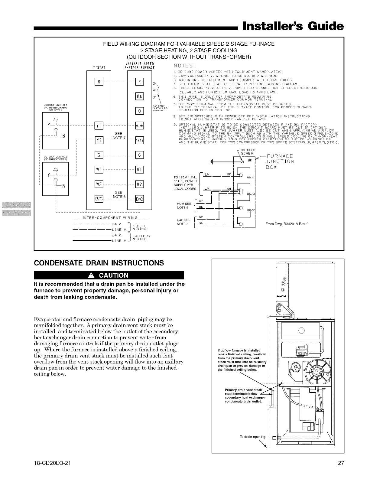
Installer's Guide
FIELD WIRING DIAGRAM FOR VARIABLE SPEED 2 STAGE FURNACE
2 STAGE HEATING, 2 STAGE COOLING
(OUTDOOR SECTION WITHOUT TRANSFORMER)
VARIABLE SPEED NOTES :
T'STAT 2-STAGE FURNACE
OUTDOORUNITNO 1
(NO TRANSFORMER)
SEE NOTE3
?UT_OO;%T&Od'
t 0/
D
Eg
E2]
D
EO
[]
SEE
NOTE 7
SEE
NOTE6
l-q
@
F-q
Fq
f-q
[]
[]
t2
i
i
I
INTER-COMPONENT WIRING
24 V. ] FIELD
LINE V.J wIRING
24 V. _ FACTORY
LINE V.J wIRINGf
0_\
FACTORY
INSTALLEO
JUMPER
I. BE SURE POWER AGREES WITH EQUIPMENT NAMEPLATE/SI
2. LOW VOLTABEI24 V. WIRING} TO BE NO. 18 A.W.G. M]N.
3. GROUNDING OF EQUIPMENT MUST COMPLY WITH LOCAL CODES.
4. SET THERMOSTAT HEAT ANTICIPATOR PER LN]T WIRING DIAGRAM=
5. THESE LEADS PROVIDE 115 V. POWER FOR CONNECTION OF ELECTRONIC AIR
CLEANER AND HUMIDIFIER MAX. LOAD 1.0 AMPS EACH.
6. THIS WIRE iS ONLY FOR THERMOSTATS REQUIRING
CONNECTION TO TRANSFORMER COMMON TERMINAL.
7. THE "Y2" TERMINAL PROM THE THERMOSTAT MUST BE WIRED
TO THE "Y" TERMINAL OF THE FURNACE CONTROL FOR PROPER BLOWER
OPERATION DURING COOLING.
8.
9=
SET DIP SWITCHES WITH POWER OFF PER INSTALLATION INSTRUCTIONS
TO SET AIRFLOW AND INDOOR FAN OFF DELAYS.
OPTIONAL HUMID]STAT iS TO BE CONNECTED BETWEEN R AND BK= FACTORY
INSTALLED JUMPER R TO BK ON THE CIRCUIT BOARD MUST BE CUT IF OPTIONAL
HUM]D[STAT IS USED. THE JUMPER MUST ALSO BE CUT WHEN APPLYING AN AIRFLOW
COMMAND SIGNAL TO THE BK INPUT SUCH AS WITH THE VARIABLE SPEED SINGLE ZONE
AND MULTI ZONE SYSTEM CONTROLLERS: ON SINGLE SPEED COOLING ONLY!NON HEAT
PUMPSYSTEMS, JUMPER Y TO 0 FOR PROPER OPERATION OF THE DELAY PROFILES
AND THE HUMID]STAT. FOR TWO COMPRESSOR OR TWO SPEED SYSTEMS,JUMPERYLOTO O.
',1 I r JUNCTION
:_ : Box
so._v,pHI-L" BKL'_WH.,
60 HZ., POWER I II
SUPPLY PER II I
LOCALCODES _ LN RHI _ --_j ,
L .,--_=F_ Bwl
,-WH I /'_'
NU_SEEJ'"''J I I1_ ',
NOTE 5 | BK
L---- °vl
WH I I
EACSEEF----/ ,I_1 ,
NOTE 5 L" BK .____ From Dwg. B342018 aev. O
CONDENSATE DRAIN INSTRUCTIONS
r'!'_ [*,]'i_lj i [0] _I
It is recommended that a drain pan be installed under the
furnace to prevent property damage, personal injury or
death from leaking condensate.
Evaporator and furnace condensate drain piping may be
manifolded together. A primary drain vent stack must be
installed and terminated below the outlet of the secondary
heat exchanger drain connection to prevent water from
damaging furnace controls if the primary drain outlet plugs
up. Where the furnace is installed above a finished ceiling,
the primary drain vent stack must be installed such that
overflow from the vent stack opening will flow into an axillary
drain pan in order to prevent water damage to the finished
ceiling below.
If upflow furnace is installed
over a finished ceiling, overflow
from the primary drain vent
stack must flow into an auxiliary
drain pan to prevent damage to
the finished ceiling below.
Primary drain vent stack
must terminate below _:
secondary heat exchanger
condensate drain outlet.
To drain opening
N
@i'
_ _ ---_ i°
°/_:--_-i !
\
18-CD20D3-21 27
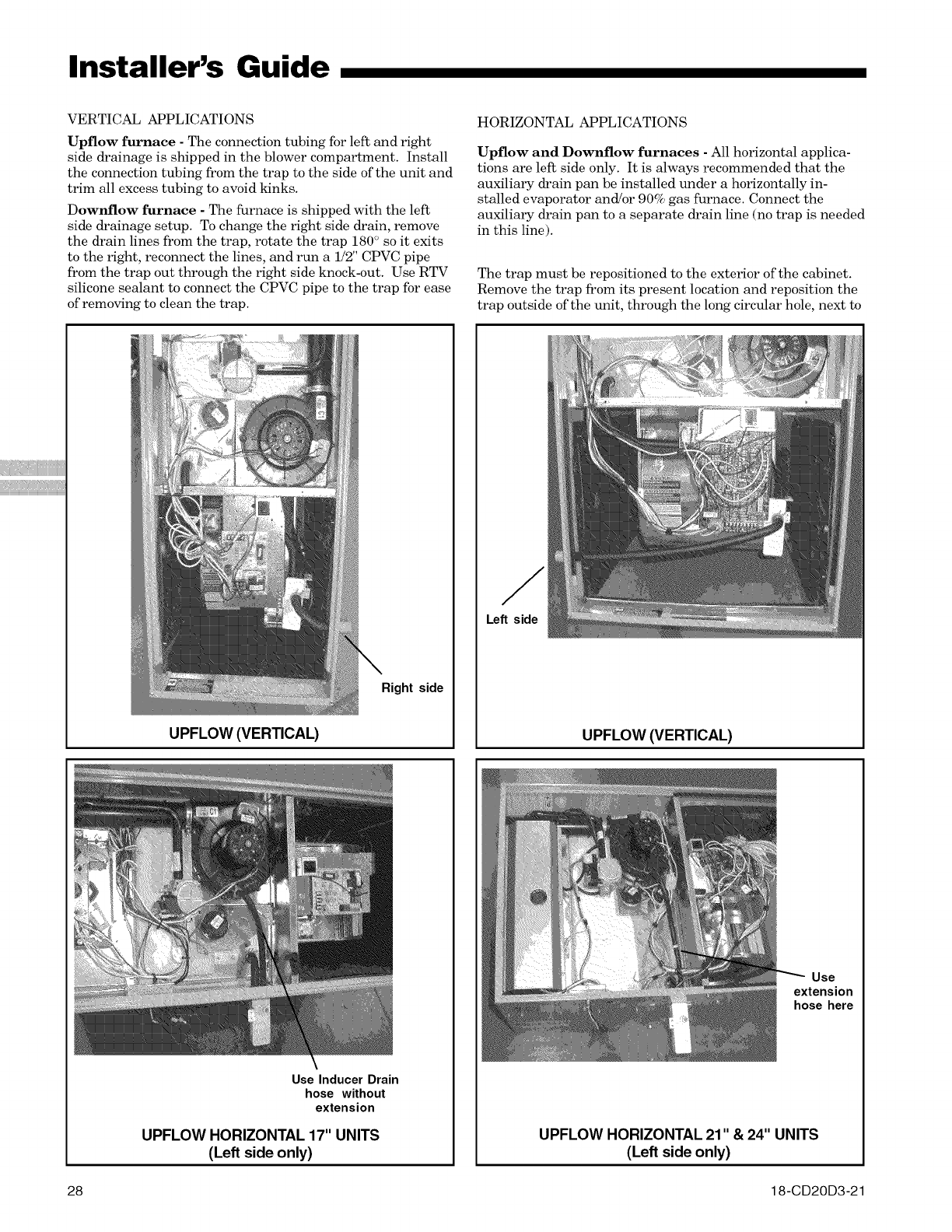
Installer's Guide
VERTICAL APPLICATIONS
Upflow furnace - The connection tubing for left and right
side drainage is shipped in the blower compartment. Install
the connection tubing from the trap to the side of the unit and
trim all excess tubing to avoid ldnks.
Downflow furnace - The furnace is shipped with the left
side drainage setup. To change the right side drain, remove
the drain lines from the trap, rotate the trap 180 ° so it exits
to the right, reconnect the lines, and run a 1/2" CPVC pipe
from the trap out through the right side knock-out. Use RTV
silicone sealant to connect the CPVC pipe to the trap for ease
of removing to clean the trap.
UPFLOW (VERTICAL)
HORIZONTAL APPLICATIONS
Upflow and Downflow furnaces -All horizontal applica-
tions are left side only. It is always recommended that the
auxiliary drain pan be installed under a horizontally in-
stalled evaporator and!or 90% gas furnace. Connect the
auxiliary drain pan to a separate drain line (no trap is needed
in this line).
The trap must be repositioned to the exterior of the cabinet.
Remove the trap from its present location and reposition the
trap outside of the unit, through the long circular hole, next to
Right side
Left side
UPFLOW (VERTICAL)
Use Inducer Drain
hose without
extension
UPFLOW HORIZONTAL 17" UNITS
(Left side only)
Use
extension
hose here
UPFLOW HORIZONTAL 21" & 24" UNITS
(Left side only)
28 18-CD20D3-21
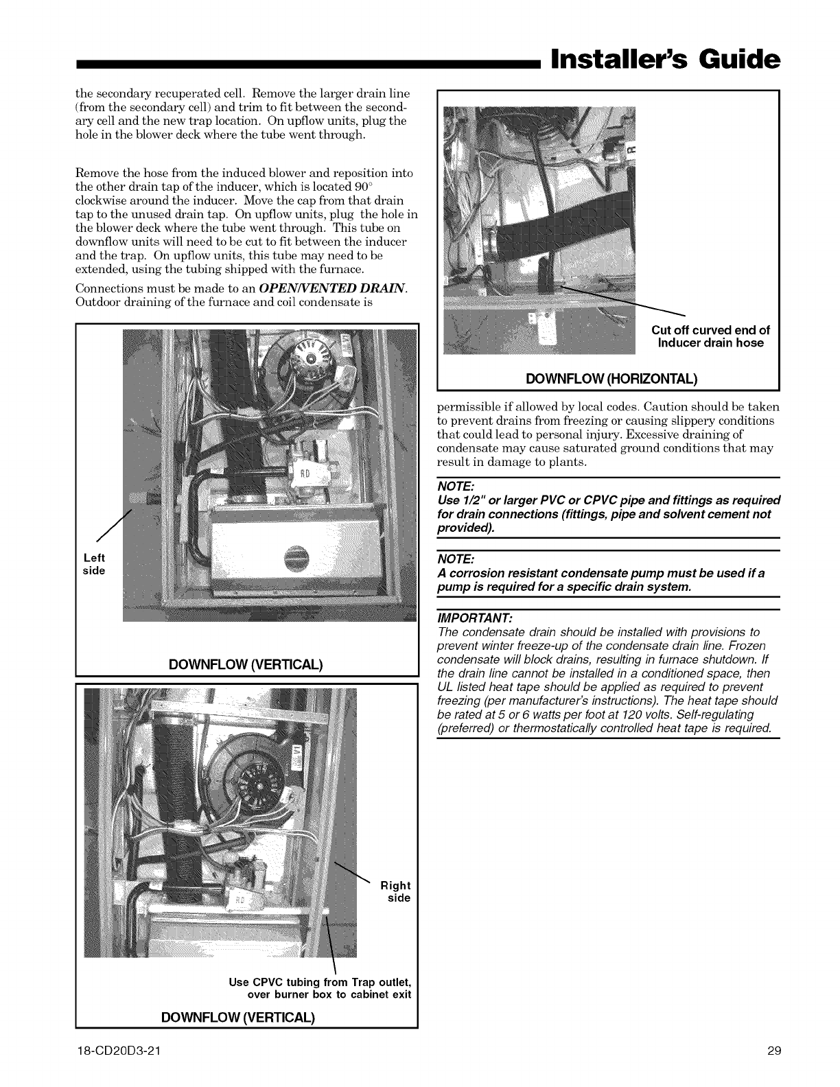
the secondary recuperated cell. Remove the larger drain line
(from the secondary cell) and trim to fit between the second-
ary cell and the new trap location. On upflow units, plug the
hole in the blower deck where the tube went through.
Remove the hose from the induced blower and reposition into
the other drain tap of the inducer, which is located 90 °
clockwise around the inducer. Move the cap from that drain
tap to the unused drain tap. On upflow units, plug the hole in
the blower deck where the tube went through. This tube on
downflow units will need to be cut to fit between the inducer
and the trap. On upflow units, this tube may need to be
extended, using the tubing shipped with the furnace.
Connections must be made to an OPEN/VENTED DRAIN.
Outdoor draining of the furnace and coil condensate is
DOWNFLOW (VERTICAL)
Right
side
Use CPVC tubing from Trap outlet,
over burner box to cabinet exit
DOWNFLOW (VERTICAL)
Installer's Guide
Cut off curved end of
Inducer drain hose
DOWNFLOW (HORIZONTAL)
permissible if allowed by local codes. Caution should be taken
to prevent drains from freezing or causing slippery conditions
that could lead to personal injury. Excessive draining of
condensate may cause saturated ground conditions that may
result in damage to plants.
NOTE:
Use 1/2" or larger PVC or CPVC pipe and fittings as required
for drain connections (fittings, pipe and solvent cement not
provided).
NOTE:
A corrosion resistant condensate pump must be used ifa
pump is required for a specific drain system.
IMPORTANT:
The condensate drain should be installed with provisions to
prevent winter freeze-up of the condensate drain line. Frozen
condensate will block drains, resulting in furnace shutdown, ff
the drain line cannot be installed in a conditioned space, then
UL listed heat tape should be applied as required to prevent
freezing (per manufacturer's instructions). The heat tape should
be rated at 5 or 6 watts per foot at 120 volts. Self-regulating
(preferred) or thermostatically controlled heat tape is required.
18-CD20D3-21 29
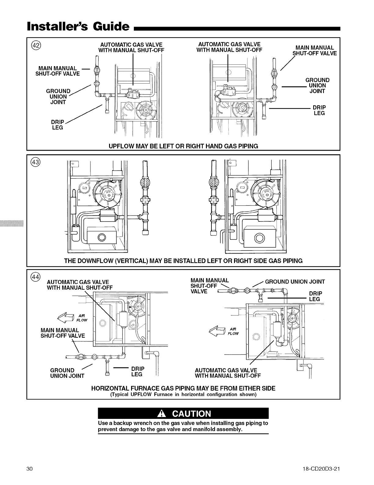
iiiiiiiiiiii
Installer's Guide
@
MAIN MANUAL m
SHUT-OFF VALVE
JOINT j_
DRIP_ .....
LEG
AUTOMATIC GAS VALVE
WITH MANUAL SHUT-OFF AUTOMATIC GAS VALVE
WITH MANUAL SHUT-OFF
UPFLOW MAY BE LEFT OR RIGHT HAND GAS PIPING
MAIN MANUAL
SHUT-OFF VALVE
/
GROUND
UNION
JOINT
DRIP
LEG
@
:_ o
c
Y
THE DOWNFLOW (VERTICAL) MAY BE INSTALLED LEFT OR RIGHT SIDE GAS PIPING
AUTOMATIC GAS VALVE
WITH MANUAL SHUT-OFF
SHUT-OFF VALVE
GRO DRI
UNION JOINT LEG !J
FLOW
MAIN MANUAL jGROUND UNION JOINT
SHUT-OFF _
VALVE _LEGDRIP
I I
AUTOMATIC GAS VALVE [_:_
WITH MANUAL SHUT-OFF !1
HORIZONTAL FURNACE GAS PIPING MAY BE FROM EITHER SIDE
(Typical UPFLOW Furnace in horizontal configuration shown)
Use a backup wrench on the gas valve when installing gas piping to
prevent damage to the gas valve and manifold assembly.
30 18-CD20D3-21
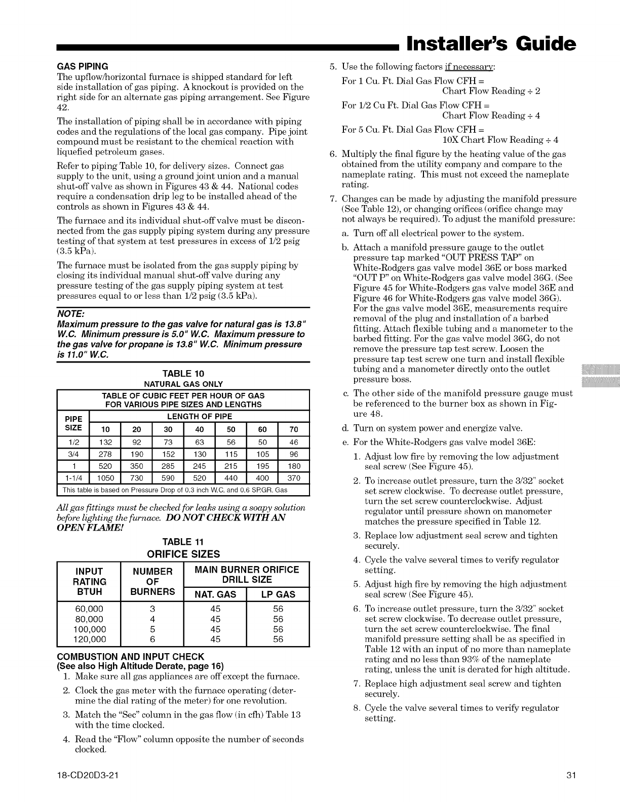
GAS PIPING
The upflow/horizontal furnace is shipped standard for left
side installation of gas piping. A knockout is provided on the
right side for an alternate gas piping arrangement. See Figure
42.
The installation of piping shall be in accordance with piping
codes and the regulations of the local gas company. Pipe joint
compound must be resistant to the chemical reaction with
liquefied petroleum gases.
Refer to piping Table 10, for delivery sizes. Connect gas
supply to the unit, using a ground joint union and a manual
shut-off valve as shown in Figures 43 & 44. National codes
require a condensation drip leg to be installed ahead of the
controls as shown in Figures 43 & 44.
The furnace and its individual shut-offvalve must be discon-
nected from the gas supply piping system during any pressure
testing of that system at test pressures in excess of 1/2 psig
(3.5 kPa).
The furnace must be isolated from the gas supply piping by
closing its individual manual shut-off valve during any
pressure testing of the gas supply piping system at test
pressures equal to or less than 1/2 psig (3.5 kPa).
NOTE:
Maximum pressure to the gas valve for natural gas is 13.8"
W.C. Minimum pressure is 5.0" W.C. Maximum pressure to
the gas valve for propane is 13.8" W.C. Minimum pressure
is 11.0" W.C.
TABLE 10
NATURAL GAS ONLY
TABLE OF CUBIC FEET PER HOUR OF GAS
FOR VARIOUS PIPE SIZES AND LENGTHS
PIPE LENGTH OF PIPE
SIZE 10 20 30 40 50 60 70
1/2 132 92 73 63 56 50 46
3/4 278 190 152 130 115 105 96
1 520 350 285 245 215 195 180
1-1/4 1050 730 590 520 440 400 370
This table is based on Pressure Drop of 0.3 inch W.C. and 0.6 SRGR. Gas
All gas fittings must be checked for leaks using a soapy solution
be[bre lighting the furnace. DO NOT CHECK WITH AN
OPEN FLAME!
TABLE 11
ORIFICE SIZES
INPUT
RATING
BTUH
60,000
80,000
100,000
120,000
NUMBER
OF
BURNERS
3
4
5
6
MAIN BURNER ORIFICE
DRILL SIZE
NAT. GAS LP GAS
45 56
45 56
45 56
45 56
COMBUSTION AND INPUT CHECK
(See also High Altitude Derate, page 16)
1. Make sure all gas appliances are offexcept the furnace.
2. Clock the gas meter with the furnace operating (deter-
mine the dial rating of the meter) for one revolution.
3. Match the "See" column in the gas flow (in cfh) Table 13
with the time clocked.
4. Read the "Flow" column opposite the number of seconds
clocked.
Installer's Guide
5. Use the following factors if necessary:
For i Cu. Ft. Dial Gas Flow CFH =
Chart Flow Reading + 2
For 1/2 Cu Ft. Dial Gas Flow CFH =
Chart Flow Reading + 4
For 5 Cu. Ft. Dial Gas Flow CFH =
10X Chart Flow Reading + 4
6. Multiply the final figure by the heating value of the gas
obtained from the utility company and compare to the
nameplate rating. This must not exceed the nameplate
rating.
7. Changes can be made by adjusting the manifold pressure
(See Table 12), or changing orifices (orifice change may
not always be required). To adjust the manifold pressure:
a. Turn off all electrical power to the system.
b. Attach a manifold pressure gauge to the outlet
pressure tap marked "OUT PRESS TAP" on
White-Rodgers gas valve model 36E or boss marked
"OUT P" on White-Rodgers gas valve model 36G. (See
Figure 45 for White-Rodgers gas valve model 36E and
Figure 46 for White-Rodgers gas valve model 36G).
For the gas valve model 36E, measurements require
removal of the plug and installation of a barbed
fitting. Attach flexible tubing and a manometer to the
barbed fitting. For the gas valve model 36G, do not
remove the pressure tap test screw. Loosen the
pressure tap test screw one turn and install flexible
tubing and a manometer directly onto the outlet
pressure boss.
c. The other side of the manifold pressure gauge must
be referenced to the burner box as shown in Fig-
ure 48.
d.
e.
Turn on system power and energize valve.
For the White-Rodgers gas valve model 36E:
1. Adjust low fire by removing the low adjustment
seal screw (See Figure 45).
2. To increase outlet pressure, turn the 3/32" socket
set screw clockwise. To decrease outlet pressure,
turn the set screw counterclockwise. Adjust
regulator until pressure shown on manometer
matches the pressure specified in Table 12.
3. Replace low adjustment seal screw and tighten
securely.
4. Cycle the valve several times to verify regulator
setting.
5. Adjust high fire by removing the high adjustment
seal screw (See Figure 45).
6. To increase outlet pressure, turn the 3/32" socket
set screw clockwise. To decrease outlet pressure,
turn the set screw counterclockwise. The final
manifold pressure setting shall be as specified in
Table 12 with an input of no more than nameplate
rating and no less than 93% of the nameplate
rating, unless the unit is derated for high altitude.
7. Replace high adjustment seal screw and tighten
securely.
8. Cycle the valve several times to verify regulator
setting.
18-CD20D3-21 31
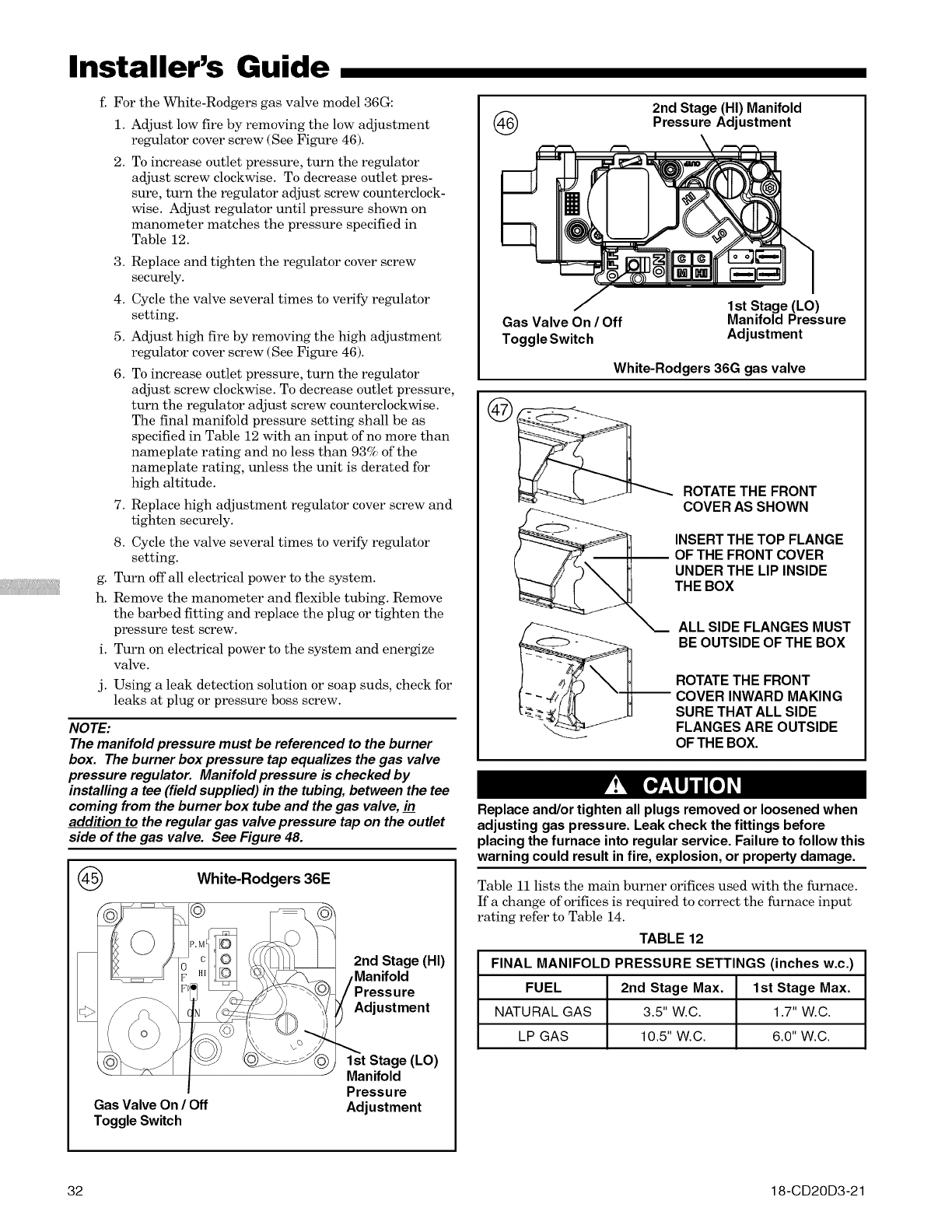
iiiiiiiiiiii
Installer's Guide
f. For the White-Rodgers gas valve model 36G:
1. Adjust low fire by removing the low adjustment
regulator cover screw (See Figure 46).
2. To increase outlet pressure, turn the regulator
adjust screw clockwise. To decrease outlet pres-
sure, turn the regulator adjust screw counterclock-
wise. Adjust regulator until pressure shown on
manometer matches the pressure specified in
Table 12.
g.
h.
i.
j.
3. Replace and tighten the regulator cover screw
securely.
4. Cycle the valve several times to verify regulator
setting.
5. Adjust high fire by removing the high adjustment
regulator cover screw (See Figure 46).
6. To increase outlet pressure, turn the regulator
adjust screw clockwise. To decrease outlet pressure,
turn the regulator adjust screw counterclockwise.
The final manifold pressure setting shall be as
specified in Table 12 with an input of no more than
nameplate rating and no less than 93% of the
nameplate rating, unless the unit is derated for
high altitude.
7. Replace high adjustment regulator cover screw and
tighten securely.
8. Cycle the valve several times to verify regulator
setting.
Turn off all electrical power to the system.
Remove the manometer and flexible tubing. Remove
the barbed fitting and replace the plug or tighten the
pressure test screw.
Turn on electrical power to the system and energize
valve.
Using a leak detection solution or soap suds, check for
leaks at plug or pressure boss screw.
NOTE:
The manifold pressure must be referenced to the burner
box. The burner box pressure tap equalizes the gas valve
pressure regulator. Manifold pressure is checked by
installing a tee (field supplied) in the tubing, between the tee
coming from the burner box tube and the gas valve, in
addition to the regular gas valve pressure tap on the outlet
side of the gas valve. See Figure 48.
@White-Rodgers 36E
2nd Stage (HI)
Manifold
Adjustment
Gas Valve On /Off
Toggle Switch
1st Stage (LO)
Manifold
Pressure
Adjustment
@2nd Stage (HI) Manifold
Pressure Adjustment
Gas Valve On /Off
Toggle Switch
1st Stage (LO)
Manifold Pressure
Adjustment
White-Rodgers 36G gas valve
ROTATE THE FRONT
COVER AS SHOWN
INSERT THE TOP FLANGE
OF THE FRONT COVER
UNDER THE LIP INSIDE
THE BOX
ALL SIDE FLANGES MUST
BE OUTSIDE OF THE BOX
ROTATE THE FRONT
COVER INWARD MAKING
SURE THAT ALL SIDE
FLANGES ARE OUTSIDE
OF THE BOX.
Replace and/or tighten all plugs removed or loosened when
adjusting gas pressure. Leak check the fittings before
placing the furnace into regular service. Failure to follow this
warning could result in fire, explosion, or property damage.
Table 11 lists the main burner orifices used with the furnace.
If a change of orifices is required to correct the furnace input
rating refer to Table 14.
TABLE 12
FINAL MANIFOLD PRESSURE SETTINGS (inches w.c.)
FUEL 2nd Stage Max. 1st Stage Max.
NATURAL GAS 3.5" W.C. 1.7" W.C.
LP GAS 10.5" W.C. 6.0" W.C.
32 18-CD20D3-21
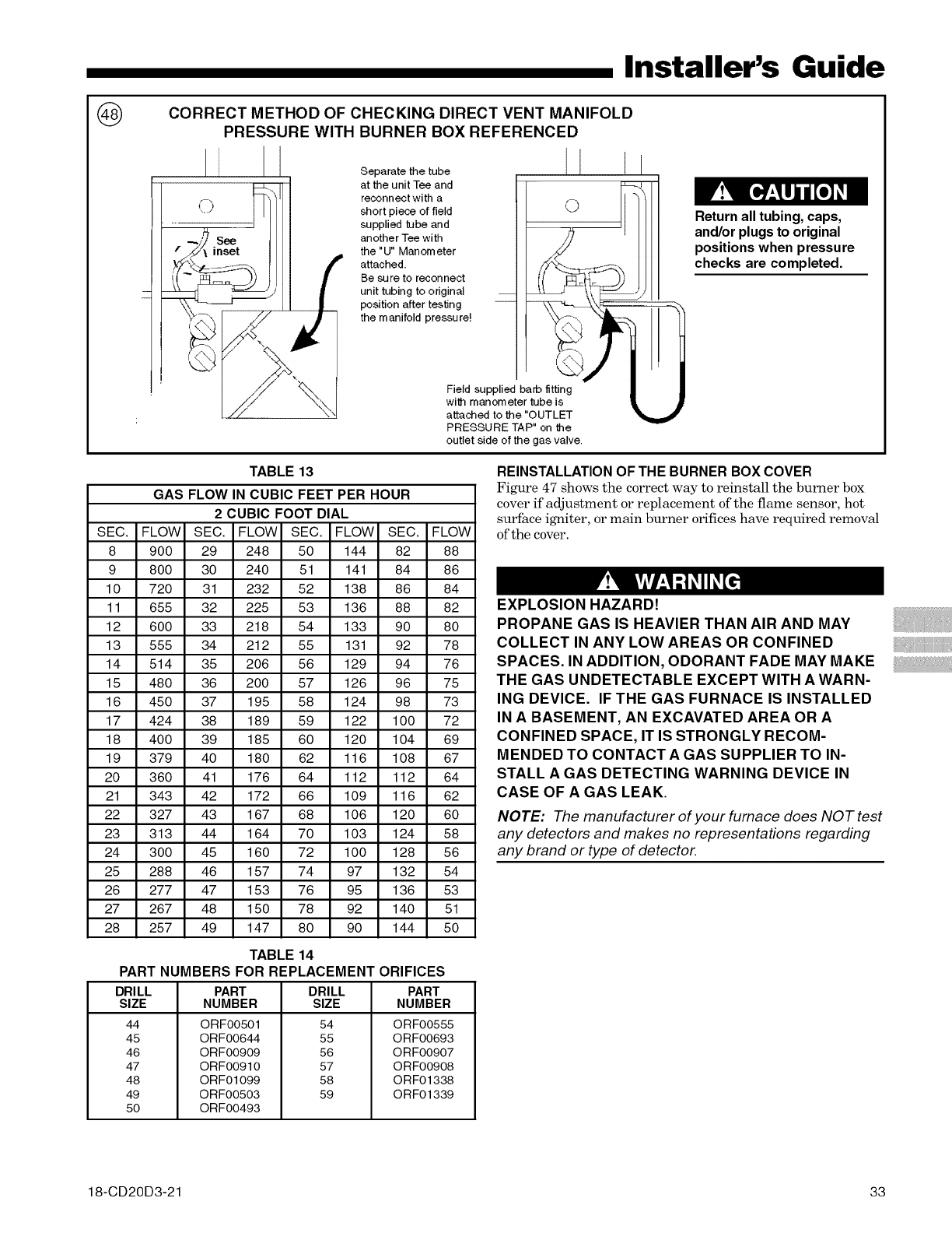
@CORRECT METHOD OF CHECKING DIRECT VENT MANIFOLD
PRESSURE WITH BURNER BOX REFERENCED
Installer's Guide
Separatethetube I I
at the unit Tee and _' !\
reconnect with a Fh I] "_t
short piece of field "J [] I
supplied tube and -- 11 I / I
another Teewith 2I /[[
the "U" Manometer .IS/ | [[
attached. //I
=esuretoreconnect I/ i 'bhJS jr
unit tubing to original -- _ _\ _/ [
position after testing -- _--_k_ L._::::::=::==
the manifold pressure! k_>/(z-\ _.,
Field supplied barb fltling_J I
with manometer tube is _.
attached to the "OUTLET '_
PRESSURE TAP" on the
outlet side of the gas valve.
TABLE 13
GAS FLOW IN CUBIC FEET PER HOUR
2 CUBIC FOOT DIAL
Return all tubing, caps,
and/or plugs to original
positions when pressure
checks are completed.
SEC. FLOW SEC. FLOW SEC. FLOW SEC. FLOW
8 900 29 248 50 144 82 88
9 800 30 240 51 141 84 86
10 720 31 232 52 138 86 84
11 655 32 225 53 136 88 82
12 600 33 218 54 133 90 80
13 555 34 212 55 131 92 78
14 514 35 206 56 129 94 76
15 480 36 200 57 126 96 75
16 450 37 195 58 124 98 73
17 424 38 189 59 122 100 72
18 400 39 185 60 120 104 69
19 379 40 180 62 116 108 67
20 360 41 176 64 112 112 64
21 343 42 172 66 109 116 62
22 327 43 167 68 106 120 60
23 313 44 164 70 103 124 58
24 300 45 160 72 100 128 56
25 288 46 157 74 97 132 54
26 277 47 153 76 95 136 53
27 267 48 150 78 92 140 51
28 257 49 147 80 90 144 50
TABLE 14
PART NUMBERS FOR REPLACEMENT ORIFICES
DRILL DRILL
SIZE SIZE
44
45
46
47
48
49
50
PART
NUMBER
ORF00501
ORF00644
ORF00909
ORF00910
ORF01099
ORF00503
ORF00493
54
55
56
57
58
59
PART
NUMBER
ORF00555
ORF00693
ORF00907
ORF00908
ORF01338
ORF01339
REINSTALLATION OF THE BURNER BOX COVER
Figure 47 shows the correct way to reinsta]] the burner box
cover if adjustment or rep]acement of the flame sensor, hot
surface igniter, or main burner orifices have required removal
of the cover.
EXPLOSION HAZARD!
PROPANE GAS IS HEAVIER THAN AIR AND MAY
COLLECT IN ANY LOW AREAS OR CONFINED
SPACES. IN ADDITION, ODORANT FADE MAY MAKE
THE GAS UNDETECTABLE EXCEPT WITH A WARN-
ING DEVICE. IF THE GAS FURNACE IS INSTALLED
IN A BASEMENT, AN EXCAVATED AREA OR A
CONFINED SPACE, IT IS STRONGLY RECOM-
MENDED TO CONTACT A GAS SUPPLIER TO IN-
STALL A GAS DETECTING WARNING DEVICE IN
CASE OF A GAS LEAK.
NOTE: The manufacturer of your furnace does NOT test
any detectors and makes no representations regarding
any brand or type of detector.
18-CD20D3-21 33
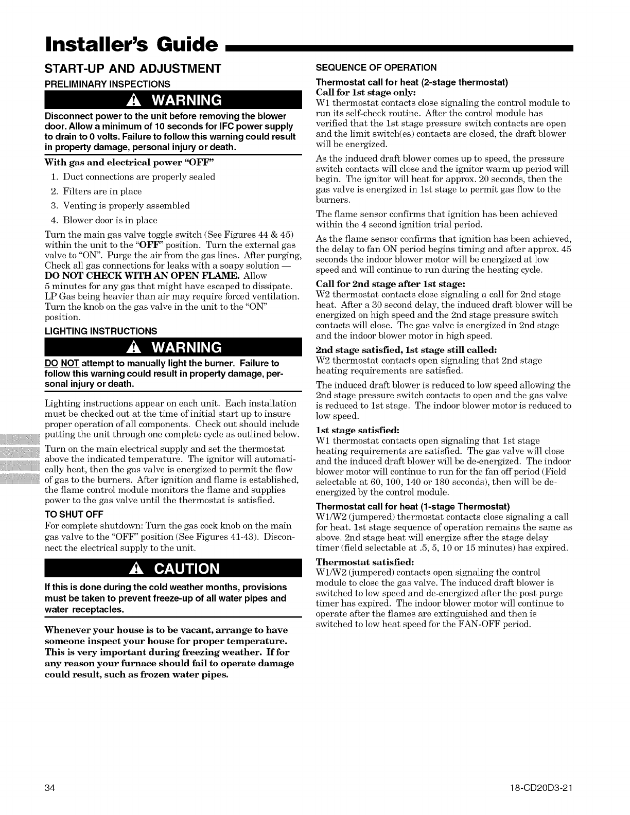
Installer's Guide
START-UP AND ADJUSTMENT
PRELIMINARY INSPECTIONS
Disconnect power to the unit before removing the blower
door. Allow a minimum of 10 seconds for IFC power supply
to drain to 0 volts. Failure to follow this warning could result
in property damage, personal injury or death.
With gas and electrical power "OFF"
1. Duct connections are properly sealed
2. Filters are in place
3. Venting is properly assembled
4. Blower door is in place
Turn the main gas valve toggle switch (See Figures 44 & 45)
within the unit to the "OFF" position. Turn the external gas
valve to "ON". Purge the air from the gas lines. After purging,
Check all gas connections for leaks with a soapy solution --
DO NOT CHECK WITH AN OPEN FLAME. Allow
5 minutes for any gas that might have escaped to dissipate.
LP Gas being heavier than air may require forced ventilation.
Turn the knot) on the gas valve in the unit to the "ON"
position.
LIGHTING INSTRUCTIONS
DO NOT attempt to manually light the burner. Failure to
follow this warning could result in property damage, per-
sonal injury or death.
Lighting instructions appear on each unit. Each installation
must be checked out at the time of initial start up to insure
proper operation of all components. Check out should include
putting the unit through one complete cycle as outlined below.
Turn on the main electrical supply and set the thermostat
above the indicated temperature. The ignitor will automati-
cally heat, then the gas valve is energized to permit the flow
of gas to the burners. After ignition and flame is established,
the flame control module monitors the flame and supplies
power to the gas valve until the thermostat is satisfied.
TO SHUT OFF
For complete shutdown: Turn the gas cock knob on the main
gas valve to the "OFF" position (See Figures 41-43). Discon-
nect the electrical supply to the unit.
If this is done during the cold weather months, provisions
must be taken to prevent freeze-up of all water pipes and
water receptacles.
Whenever your house is to be vacant, arrange to have
someone inspect your house for proper temperature.
This is very important during freezing weather. If for
any reason your furnace should fail to operate damage
could result, such as frozen water pipes.
SEQUENCE OF OPERATION
Thermostat call for heat (2-stage thermostat)
Call for 1st stage only:
W1 thermostat contacts close signaling the control module to
run its self-check routine. After the control module has
verified that the 1st stage pressure switch contacts are open
and the limit switch(es) contacts are closed, the draft blower
will be energized.
As the induced draft blower comes up to speed, the pressure
switch contacts will close and the ignitor warm up period will
begin. The ignitor will heat for approx. 20 seconds, then the
gas valve is energized in 1st stage to permit gas flow to the
burners.
The flame sensor confirms that ignition has been achieved
within the 4 second ignition trial period.
As the flame sensor confirms that ignition has been achieved,
the delay to fan ON period begins timing and after approx. 45
seconds the indoor blower motor will be energized at low
speed and will continue to run during the heating cycle.
Call for 2rid stage after 1st stage:
W2 thermostat contacts close signaling a call for 2nd stage
heat. After a 30 second delay, the induced draft blower will be
energized on high speed and the 2nd stage pressure switch
contacts will close. The gas valve is energized in 2nd stage
and the indoor blower motor in high speed.
2nd stage satisfied, 1st stage still called:
W2 thermostat contacts open signaling that 2nd stage
heating requirements are satisfied.
The induced draft blower is reduced to low speed allowing the
2nd stage pressure switch contacts to open and the gas valve
is reduced to 1st stage. The indoor blower motor is reduced to
low speed.
1st stage satisfied:
W1 thermostat contacts open signaling that 1st stage
heating requirements are satisfied. The gas valve will close
and the induced draft blower will be de-energized. The indoor
blower motor will continue to run for the fan off period (Field
selectable at 60, 100, 140 or 180 seconds), then will be de-
energized by the control module.
Thermostat call for heat (1-stage Thermostat)
W1/W2 (jumpered) thermostat contacts close signaling a call
for heat. 1st stage sequence of operation remains the same as
above. 2nd stage heat will energize after the stage delay
timer (field selectable at .5, 5, 10 or 15 minutes) has expired.
Thermostat satisfied:
W1/W2 (jumpered) contacts open signaling the control
module to close the gas valve. The induced draft blower is
switched to low speed and de-energized after the post purge
timer has expired. The indoor blower motor will continue to
operate after the flames are extinguished and then is
switched to low heat speed for the FAN-OFF period.
34 18-CD20D3-21
CONTROL AND SAFETY SWITCH
ADJUSTMENTS
LIMIT SWITCH CHECK OUT
The limit switch is a safety device designed to close the gas
valve should the furnace become overheated. Since proper op-
eration of this switch is important to the safety of the unit, it
must be checked out on hlitial start up by the hlstaller.
To check for proper operation of the limit switches, set the
thermostat to a temperature higher than the indicated
temperature to bring on the gas valve. Restrict the airflow by
blocking the return air (disconnecting the indoor blower may
trip the inducer limit). When the furnace reaches the maxi-
* - This setting is equivalent to BAY24X045 relay
benefit.
**- This selection provides ENHANCED MODE, which
is a ramping up and ramping down of the blower
speed to provide improved comfort, quietness, and
potential energy savings. See Wiring Diagram
notes on the unit or in the Service Facts for com-
plete wiring setup for ENHANCED MODE. The
graph which follows, shows the ramping process.
80%
100% if necessary
OFF
50% 50%
:ast Cooling Efficiency
I,I 75 I I 3I
minute minutes minutes
OFF
See Wiring Diagram on the unit or in the Service Facts
for complete wiring setup for Enhanced Mode.
mum outlet temperature as shown on the rating plate, the
burners must shut off. If they do not shut off after a reason-
able time and overheating is evident, a faulty limit switch is
probable and the limit switch must be replaced. After
checking the operation of the limit control, be sure to remove
the paper or cardboard from the return air inlet. Refer to
Service Facts for additional instructions.
AIRFLOW ADJUSTMENT
Check inlet and outlet air temperatures to make sure they
are within the ranges specified on the furnace rating name-
plate. If the airflow needs to be increased or decreased, see
the Airflow Label on the furnace or the unit's Service Facts for
information on changing the speed of the blower motor for
your specific model. Blower speed changes are made on the
Integrated Furnace Control (IFC).
There is a bank of 8 dip switches located near the thermostat
connections to the Integrated Furnace Control. The dip
switches work in pairs to match the airflow for the outdoor
unit size (tons), cooling airflow adjustment, cooling off-delay
options, and furnace heating airflow adjustment.
Installer's Guide
Disconnect power to the unit before removing the blower
door. Allow a minimum of 10 seconds for IFC power supply
to drain to 0 volts. Failure to follow this warning could result
in property damage, personal injury or death.
INDOOR BLOWER TIMING
Heating: The integrated furnace control module controls the
indoor blower. The blower start is fixed at 45 seconds after
ignition. The FAN-OFF period is field selectable by dip
switches SW-2, #1 and #2 at 60, 100, 140, or 180 seconds.
The factory setting is 100 seconds.
WI-W2 stage delay (jumpered together) is field selectable by
dip switch SW-1, #1 and #2 at .5, 5, 10 or 15 minutes. The
factory setting is 10 minutes. (See wiring diagram).
Cooling: The fan delay-offperiod is set by dip switches on the
Integrated Furnace Control. The options for cooling delay off
is field selectable by dip switches #5 and #6.
The following table and graph explain the delay-off settings:
COOLING OFF - DELAY OPTIONS
NOMINAL
SWITCH SETTINGS SELECTION AIRFLOW
5 - OFF 6 - OFF NONE SAME
5 - ON 6 - OFF 1.5 MINUTES 100% *
5 - OFF 6 - ON 3 MINUTES 50%
5-ON 6-ON ** 50- 100%
This unit is equipped with a blower door switch which cuts
power to the blower and gas valve causing shutdown when the
door is removed. Operation with the door removed or ajar can
permit the escape of dangerous fumes. All panels must be
securely closed at all times for safe operation of the furnace.
NOTE TO INSTALLER
Review the following warnings with the owner. Review
contents of USER'S INFORMATION MANUAL with the
owner.
ROOM AIR THERMOSTAT
HEAT ANTICIPATOR ADJUSTMENT
Set the thermostat heat anticipator according to the current
flow measured, or the settings found in the notes on the
furnace wiring diagram (found in the SERVICE FACTS or
inside the furnace casing).
INSTRUCTIONS TO THE OWNERS
In the event that electrical, fuel, or mechanical failures
occur, the owner should immediately turn the gas
supply off at the manual gas valve, located in the burner
compartment. Also turn off electrical power to the
furnace and contact the service agency designated by
your dealer.
BURNER BOX TEMPERATURE LIMIT DEVICE
All models are equipped with a manual reset temperature
limit located on the burner box. In case of excessive tempera-
ture, the limit will open and cause the circuit to open which
shuts offall flow of gas.
18-CD20D3-21 35
Installer's Guide
ABNORMAL CONDITIONS
1. EXCESSIVE COMBUSTION PRESSURE (WIND IN
EXCESS OF 40 MP.H.) VENT OR FLUE BLOCKAGE
On a call for heat, the variable speed draft inducer must
first ramp up to speed and close the pressure switch
before the ignition sequence is allowed to begin. If the
pressure switch does not close, the motor will ramp up to
maximum speed and continue to operate there for about
1 minute. After one minute the integrated furnace
control will turn the motor off for about 30 seconds then
back on in an attempt to reestablish proper operation.
This condition is indicative of a highly restricted or
blocked inlet or outlet vent pipe or a failed pressure
switch.
If pressure against induced draft blower outlet becomes
excessive, the pressure switch will open. If the pressure
switch is open for more than 3.5 seconds, the variable
speed draft inducer will speed up and attempt to close
the pressure switch.
If the pressure switch is not closed within 12 seconds or if
the maximum speed of the motor is reached, the draft
inducer sends a fault signal to the integrated furnace
control. If the unit is operating in second stage, an
inducer fault will cause the furnace control to transition
the system to first stage and it will operate there for 10
minutes before attempting to run again in second stage.
If the unit is operating in first stage, an inducer fault will
cause the furnace control to shut the system down and
wait 30 seconds before attempting to reestablish
operation in first stage.
2. LOSS OF FLAME
If loss of flame occurs during a heating cycle, or flame is
not present at the sensor, the flame control module will
close the gas valve. The flame control module will then
recycle the ignition sequence, then if ignition is not
achieved, it will shut offthe gas valve and lock out the
system.
3. POWER FAILURE
If there is a power failure during a heating cycle, the
system will restart the ignition sequence automatically
when power is restored, if the thermostat still calls for
heat.
4. GAS SUPPLY FAILURE
If loss of flame occurs during a heating cycle, the system
integrated control module will recycle the ignition
sequence, then if ignition is not achieved, the integrated
control module will shut off the gas valve and lock out the
system.
5. INDUCED DRAFT BLOWER FAILURE
Please refer to the variable speed &'aft inducer trouble-
shooting manual for diagnostic assistance.
6. CONDENSATE DRAIN BLOCKAGE
If the condensate drain is blocked, either by debris,
improper draining, or by freezing condensate, the pres-
sure switch will sense the accumulation of condensate in
the furnace drain pan.
The unit will not operate properly until the condensate
drain has been cleared, and the condensate flows freely.
7. RESET AFTER LOCKOUT
When the integrated control module has shut the system
down and gone into lockout, the system must be manu-
ally reset before the unit will restart. The system can be
reset by turning the system power offfor more than
i second, or by removing 24VAC from the control for more
than 1 second, or by removing the thermostat call for
heat for more than 1 second but less than 20 seconds.
8. RESET AFTER BURNER BOX LIMIT SHUTDOWN
If the furnace shuts down, one thing that can be checked
is the burner box temperature limit switch. It is located
on the bottom of the burner box. The vent and combus-
tion air inlet terminations should be checked for block-
age. If blockage exists, clear the problem and then the
reset button may be depressed. If there is no blockage
of the terminations, the limit switch must be reset
by a qualified servicer.
36 18-CD20D3-21
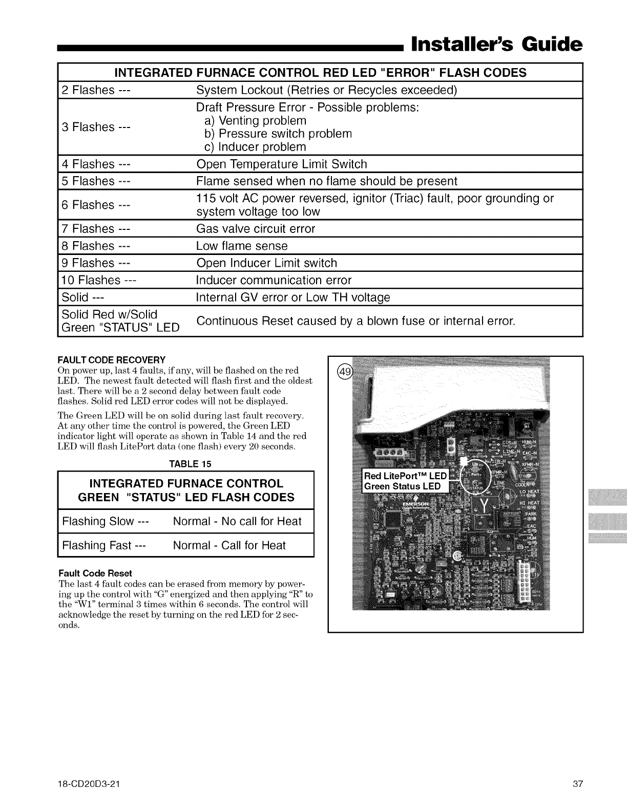
Installer's Guide
INTEGRATED FURNACE CONTROL RED LED "ERROR" FLASH CODES
2 Flashes --- System Lockout (Retries or Recycles exceeded)
Draft Pressure Error- Possible problems:
a) Venting problem
b) Pressure switch problem
c) Inducer problem
Open Temperature Limit Switch
Flame sensed when no flame should be present
115 volt AC power reversed, ignitor (Triac) fault, poor grounding or
system voltage too low
Gas valve circuit error
3 Flashes ---
4 Flashes ---
5 Flashes---
6 Flashes---
7 Flashes ---
8 Flashes --- Low flame sense
9 Flashes --- Open Inducer Limit switch
10 Flashes --- Inducer communication error
Solid --- Internal GV error or Low TH voltage
Solid Red w/Solid Continuous Reset caused by a blown fuse or internal error.
Green "STATUS" LED
FAULT CODE RECOVERY
On power up, last 4 faults, if any, will be flashed on the red
LED. The newest fault detected will flash first and the oldest
last. There will be a 2 second delay between fault code
flashes. Solid red LED error codes will not be displayed.
The Green LED will be on solid during last fault recovery.
At any other time the control is powered, the Green LED
indicator light will operate as shown in Table 14 and the red
LED will flash LitePort data (one flash) every 20 seconds.
TABLE 15
INTEGRATED FURNACE CONTROL
GREEN "STATUS" LED FLASH CODES
Flashing Slow --- Normal - No call for Heat
Flashing Fast --- Normal - Call for Heat
Fault Code Reset
The last 4 fault codes can be erased from memory by power-
ing up the control with "G" energized and then applying "R" to
the "WI" terminal 3 times within 6 seconds. The control will
acknowledge the reset by turning on the red LED for 2 sec-
onds.
Green Status LED
18-CD20D3-21 37
Installer's Guide
Tl_e
6200 Troup Highway
Tyler, TX 75707
For more information contact
your local dealer (distributor)
38
Since the manufacturer has a policy of continuous product and product data improvement, it reserves the right
to change design and specifications without notice.
18-CD20D3-21
