TRANE Furnace/Heater, Gas Manual L0903066
User Manual: TRANE TRANE Furnace/Heater, Gas Manual TRANE Furnace/Heater, Gas Owner's Manual, TRANE Furnace/Heater, Gas installation guides
Open the PDF directly: View PDF ![]() .
.
Page Count: 24
IIIIIIIIIIIIIIIIIIIIIIIIIIII
18- CD20 D1 - 18
AVAILABLE IN FRENCH CANADIAN (FC)
Variable Speed, 2-Stage
Upflow /Horizontal and Downflow /Horizontal,
Gas-Fired Furnaces, "Fan Assisted
Combustion System"
*UD060R9V3K *UD100R9V5K
*UD080R9V3K *UD120R9V5K
*UD080R9V4K *UD140R9V5K
*UD100R9V3K *DD060R9V3F
*__First letter may be"A" or "T"
ALL phases of this installation must comply with NATIONAL, STATE AND LOCAL CODES
*DD080R9V3F
*DD100R9V5F
*DD120R9V5F
IMPORTANT -- This Document is customer property and is to remain with this unit.
Please return to service information pack upon completion of work.
For VENT SIZING INFORMATION see:
USA --
National Fuel Gas Code ......... ANSI Z223.1/NFPA 54 (latest version)
CANADA --
Natural Gas Installation Code ...... CAN/CGA-B149.1 (latest version)
Propane Installation Code ............. CAN/CGA-B149.2 (latest version)
USA/CANADA ALTERNATE --
Category I Venting Guide ......... Pub. No. 18-CH23D1 (latest version)
Downflow /Horizontal* Upflow /Horizontal*
o
*Horizontal Conversion for these furnaces may be left or right side rotation.
A341789P03
Installer's Guide
SAFETY SECTION
The following safety practices and precautions must be
followed during the installation, servicing, and operation of
this furnace.
1.
2.
Use only with the type of gas approved for this furnace.
Refer to the furnace rating plate.
Install this furnace only in a location and position as
specified in "Location and Clearances" (page 3), of these
instructions.
3. Provide adequate combustion and ventilation air to the
furnace space as specified in "Air for Combustion and
Ventilation" (pages 7-8), of these instructions.
4. Combustion products must be discharged outdoors.
Connect this furnace to an approved vent system only, as
specified in the "Venting" section (pages 13-14), of these
instructions.
5. Never test for gas leaks with an open flame. Use a
commercially available soap solution made specifically
for the detection of leaks to check all connections, as
specified in "Gas Piping" (page 18) of these instructions.
6. Always install the furnace to operate within the furnace's
intended temperature-rise range with a duct system
which has an external static pressure within the allow-
able range, as specified on the unit rating plate. Airflow
with temperature rise for cfm versus static is shown in
the Service Facts accompanying this furnace.
7. When a furnace is installed so that supply ducts carry air
circulated by the furnace to areas outside the space
containing the furnace, the return air shall also be
handled by a duct(s) sealed to the furnace casing and
terminating outside the space containing the furnace.
8. A gas-fired furnace for installation in a residential
garage must be installed as specified in "Location and
Clearances" section (page 3) of these instructions.
9. The furnace may be used for temporary heating of
buildings or structures under construction only when the
following conditions have been met:
a. The furnace venting system must be complete and
installed per manufacturer's instructions.
b. The furnace is controlled only by a room thermostat
(no field jumpers).
c. The furnace return air duct must be complete and
sealed to the furnace and clean air filters are in
place.
d. The furnace input rate and temperature rise must be
verified to be within nameplate marking.
e. 100% of the furnace combustion air requirement must
come from outside the structure.
f. The furnace return air temperature range is between
55 and 80 degrees Fahrenheit.
g. Clean the furnace, duct work, and components upon
substantial completion of the construction process,
and verify furnace operating conditions including
ignition, input rate, temperature rise and venting,
according to the manufacturer's instructions.
10. This product must be gas piped by a Licensed Plumber or I
Gas Fitter in the Commonwealth of Massachusetts. I
CARBON MONOXIDE POISONING HAZARD
Failure to follow the steps outlined below for each
appliance connected to the venting system being
placed into operation could result in carbon monoxide
poisoning or death.
The following steps shall be followed for each appliance
connected to the venting system being placed into
operation, while all other appliances connected to the
venting system are not in operation:
1. Seal any unused openings in the venting system.
2. Inspect the venting system for proper size and
horizontal pitch, as required in the National Fuel Gas
Code, ANSI Z223.1/NFPA 54 or the CAN/CGA B149
Installation Codes and these instructions. Determine
that there is no blockage or restriction, leakage,
corrosion and other deficiencies which could cause an
unsafe condition.
3.
4.
5.
6.
7.
8.
As far as practical, close all building doors and
windows and all doors between the space in which the
appliance(s) connected to the venting system are
located and other deficiencies which could cause an
unsafe condition.
Close fireplace dampers.
Turn on clothes dryers and any appliance not
connected to the venting system. Turn on any exhaust
fans, such as range hoods and bathroom exhausts, so
they are operating at maximum speed. Do not operate
a summer exhaust fan.
Follow the lighting instructions. Place the appliance
being inspected into operation. Adjust the thermostat
so appliance is operating continuously.
If improper venting is observed during any of the above
tests, the venting system must be corrected in
accordance with the National Fuel Gas Code,
ANSI Z221.1/NFPA 54 and/or CAN/CGA B149
Installation Codes.
After it has been determined that each appliance
connected to the venting system properly vents where
tested as outlined above, return doors, windows,
exhaust fans, fireplace dampers and any other gas-fired
burning appliance to their previous conditions of use.
Safety signal words are used to designate a degree or level of
seriousness associated with a particular hazard. The signal
words for safety markings are WARNING and CAUTION.
a. WARNING indicates a potentially hazardous situation
which, if not avoided, could result in death or serious
injury.
b. CAUTION indicates a potentially hazardous situation
which, if not avoided, may result in minor or moderate
injury. It is also used to alert against unsafe practices
and hazards involving only property damage.
FIRE OR EXPLOSION HAZARD
Failure to follow the safety warnings exactly could result in
serious injury, death or property damage.
Improper servicing could result in dangerous operation,
serious injury, death, or property damage.
© 2008 Trane All Rights Reserved 18-CD20D1-1 8
GENERAL INSTALLATION INSTRUCTIONS
The manufacturer assumes no responsibility for equipment
installed in violation of any code or regulation.
It is recommended that Manual J of the Air Conditioning
Contractors Association (ACCA) or A.R.I. 230 be followed in
estimating heating requirements. When estimating heating
requirements for installation at Altitudes above 2000 ft.,
remember the gas input must be reduced (See GAS INPUT
ADJUSTMENT).
Material in this shipment has been inspected at the
factory and released to the transportation agency
without known damage. Inspect exterior of carton for
evidence of rough handling in shipment. Unpack
carefully after moving equipment to approximate
location. If damage to contents is found, report the
damage immediately to the delivering agency.
Codes and local utility requirements governing the installa-
tion of gas fired equipment, wiring, plumbing, and flue
connections must be adhered to. In the absence of local codes,
the installation must conform with latest edition of the
National Fuel Gas Code ANSI Z223.1 • National Installation
Code, CAN/CGA B149.1. The latest code may be obtained
from the American Gas Association Laboratories, 400 N.
Capitol St. NW, Washington D.C. 20001.
1-800-699-9277 or www.aga.org
These furnaces have been classified as Fan Assisted
Combustion system CATEGORY I furnaces as required by
ANSI Z21.47 "latest edition" and CAN/CGA 2.3. Therefore
they do not require any special provisions for venting other
than what is indicated in these instructions. (Category I
defined on page 13).
To prevent shortening its service life, the furnace should not
be used as a "Construction Heater" during the finishing
phases of construction until the requirements listed in item
9, a-g of the safety section of this publication have been met.
Condensate in the presence of chlorides and fluorides from
paint, varnish, stains, adhesives, cleaning compounds, and
cement create a corrosive condition which may cause rapid
deterioration of the heat exchanger.
Do not install the furnace in a corrosive or contaminated
atmosphere.
These furnaces are not approved or intended for installation
in manufactured (mobile) housing, trailers, or recreational
vehicles. Failure to follow this warning could result in
property damage, personal injury, or death.
Do not install the furnace directly on carpeting, tile or other
combustible material other than wood flooring. For vertical
downflow application, subbase (BAYBASE205) must be
used between the furnace and combustible flooring. When
the downflow furnace is installed vertically with a cased coil,
a subbase is not required.
Installer's Guide
Contents
Installation Instructions
General Installation Instructions
Location and Clearances
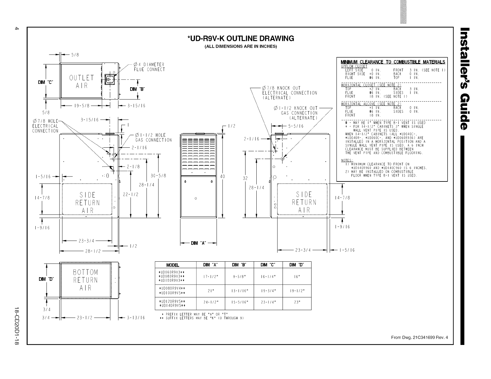
Outline Drawing
Upflow Installation
Downflow Installation
Horizontal Installation
Air for Combustion and Ventilation
Duct Connections
Return Air Filters
General Venting Instructions
Venting into a Masonry Chimney
Electrical Connections
Field Wiring Diagrams
Gas Piping
Combustion and Input Check
High Altitude Derate
Start Up and Adjustment
Preliminary Inspections
Lighting Instructions
Sequence Of Operation
Control and Safety Switch Adjustment
Abnormal Conditions
IFC Error Flash Codes
LOCATION AND CLEARANCES
The location of the furnace is normally selected by the
architect, the builder, or the installer. However, before the
furnace is moved into place, be sure to consider the following
requirements:
1. Is the location selected as near the chimney or vent and
as centralized for heat distribution as practical?
2. Do all clearances between the furnace and enclosure
equal or exceed the minimums stated in Clearance Table
on the Outline Drawings.
3. Is there sufficient space for servicing the furnace and
other equipment? A minimum of 24 inches front accessi-
bility to the furnace must be provided. Any access door
or panel must permit removal of the largest component.
4. Are there at least 3 inches of clearance between the
furnace combustion air openings in the front panel and
any closed panel or door provided?
5. Are the ventilation and combustion air openings large
enough and will they remain unobstructed? If outside
air is used, are the openings set above the highest snow
accumulation level? (See the Air for Combustion and
Ventilation section.)
6. Allow sufficient height in supply plenum above the
furnace to provide for cooling coil installation, if the
cooling coil is not installed at the time of this furnace
installation.
18-CD20D1-18 3
Go
&
I:D
o
I:D
i
Go
t
DIM "C"
t
5/8
¢7/8 HOLE_.. 3-1S/16_'i
ELECTRICAL _ I
CONNECTION \LLLLLLLLL_.... AI
I-5/16-_ _ .:0
14-7/8
J_
I-9/16
•,,_ 5/8
J" 'h F_4 DIAMETER
t ,o.JP"FLUECONNECT
T .... __
AIR B-
19-5/8_ _- 3-15/16
vI
!
!
jSIDE
j RETURN ic
= 28- I/2 -_'-
El
_- /_1-1/2 HOLE
[/ GAS CONNECTION
€-_ 2-1/16
-,- 2- I/8 l
-T1
30-5/8
28-1/4
22-1/21 l
_ I/2
DIM "P"
3/4
3/4 =
BOTTOM l!
RETURN
AIR
23-1/2_ L3-13/16
i
*UDIR9VIK OUTLINE DRAWING
(ALL DIMENSIONS ARE IN INCHES)
40
o
I/2
--_7/8 KNOCK OUT
ELECTRICAL CONNECTION
(ALTERNATE)
\ _1-1/2 KNOCKOUT_
\GAS CONNECTION_
\ (ALTERNATE)/
_,__ .... ,
S2 Io •. o ,
.j SIDE
II sl RETURNj
I I L...................___!___................J
MODEL DIM "A" DIM °B°DIM "C" DIM "D°
*UDOBORgVS*_
*UDOBOR9V3** 17-I/2 II 9-5/8" 16-IX4 II 16 II
*UDIOORgV3**
*UDOBOR9V4**
*UDIOORgVB_ 2111 13-1/IBII 191_/411 19-I/211
*UDIBORgV5** 24-I/2 II l§-B/IB II 2_11/4 II 23"
*UDI4OR9VB**
PREFIX LETTER MAY BE IIAIIOR IITII
H SUFFIX LETTERS MAY BE IIKII(0 THROUGH 9)
MINIMUMCLEARANCETO COMBUSTIBLEMATERIALS
UPFLOWCLOSET
LEFT SIBE O IN FRONT 3 IN (SEE NOTE I)
RIGHT SIDE +O IN BACK O IN.
FLUE #6 IN TOP I IN
HORIZONTAL CLOSET (SEE NOTE 2)
TOP +2 IN BACK 3 IN
FLUE #6 IN SIDES I IN
FRONT 18 IN (SEE NOTE I)
HORIZONTAL ALCOVE (SEE NOTE 2)
TOP +1 IN BACK 0 IN
FLUE #6 IN SIDES O IN
FRONT 18 IN
# - MAv BE III WHEN TYPE B-I VENT IS USED
+- FORI_-I/B II CABINETS SII WHENSINGLE
WALL VENT PIPE IS USED,
WHEN 14-1/211 CABINETS (ALL *UDO4OC-,
÷UDO4OR-, *UDO60C-, AND _UDOGOR936) ARE
INSTALLED IN A HORIZONTAL POSITION AND A
SINGLE WALL VENT PIPE IS USED, A 6 INCH
CLEARANCE MUST BE SUPPLIED BETWEEN
THE VENT PIPE AND COMBUSTIBLE FLOORING
NOTES:
I) MINIMUM CLEARANCE TO FRONT ON
_UBI_OR960 AND _UDI40C960 IS 6 INCHES.
2) MAY BE INSTALLED ON COMBUSTIBLE
FLOOR WHEN TYPE B-I VENT IS USED
T
14-7/8
I-9/16
I-5/16
From Dwg. 21C341699 Rev. 4
iii
I
I
ii E
II
n_
Oo
i
©
bo
0
Oo
ol
DIM "C"
5/8
5/8
,/+
SIDE PANEL CUTOUT_
HORIZONTAL VENTING
THROUGH CABINET
7/8
ELECTRICAL
CONNECTION
¢11/2 HOLE
GAS CONNECTION
I/2
I/2 1
_51/2
_2 I/8
2 1/16
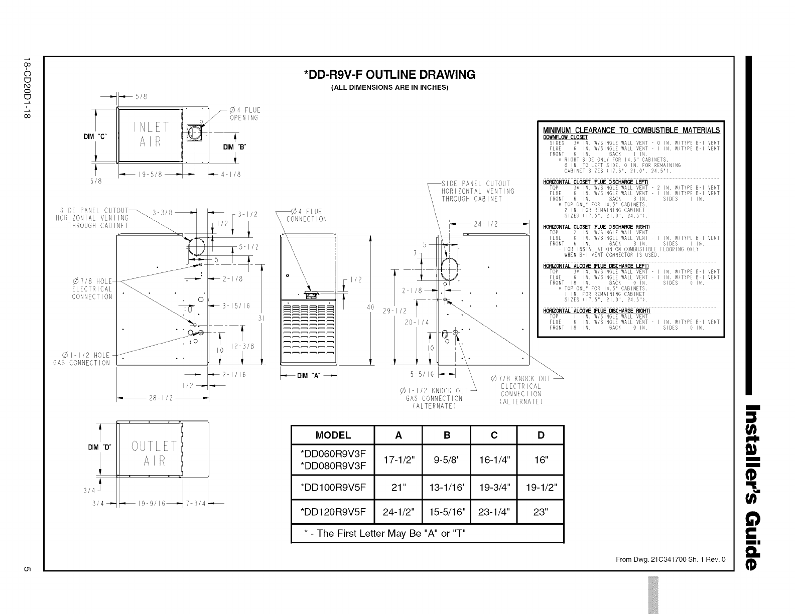
*DD-R9V-F OUTLINE DRAWING
(ALL DIMENSIONS ARE IN INCHES)
DIM "A" _d
4O
SIDE PANEL CUTOUT
HORIZONTAL VENTING
THROUGH CABINET
5
7
T f N
2_/+_._-_ .
++,,+I
20 I/4
\
¢11/2 KNOCK OUT"
GAS CONNECTION
(ALTERNATE)
MINIMUMCLEARANCE TO COMBUSTIBLEMATERIALS
DOWNFL0W CLOSET
SIDES 3+ IN W/SINGLE WALL VENT 0 IN W/TYPE B I VENT
FLuE 6 IN W/SINGLE WALL VENT I IN W/TYPE B I VENT
FRONT 6IN BACK I IN
÷ RIGHT SIDE ONLY FOR 145" CABINETS,
0 IN TO LEFT SIDE 0 IN FOR BEMAINING
CABINET SIZES {175", 210 II , 245 II }
HI_RIZONTAL CLOSET )FLUE DISCHARGE LEFT}
TOP 5÷ IN W/SINGLE WALL VENT 2 IN W/TYPE B I VENT
FLuE 6 IN W/SINGLE WALL VENT I IN W/TYPE B I VENT
FRONT 6 IN BACK 3 IN SIDES I IN
÷ TOP ONLY FOR 145" CABINETS
2 IN FOR REMAINING CABINET
SIZES {175", 210", 245")
HORIZONTAL CLOSET )FLUE DISCHAROE RIGHT)
TOP 2 IN W/SINGLE WALL VENT
FLUE 6 IN W/SINGLE WALL VENT I IN W/TYPE B I VENT
FRONT 6 IN BACK 3 IN SIDES I IN
FOR INSTALLATION ON COMBUSTIBLE FLOORING ONLY
WHEN B I VENT CONNECTOR IS USED
HORIZONTAL ALCOVE }FLUE DISCHARGE LEFT)
TOP S÷ IN W/SINGLE WALL VENT
FLUE 6 IN W/SINGLE WALL VENT
FRONT 18 IN BACK 0 IN
÷ TOP ONLY FOR 145" CABINETS
I IN FOR REMAINING CABINET
SIZES {175", 210", 245")
IN W/TYPE B I VENT
IN WTVPE B I VENT
SIDES 0 IN
HORIZONTAL ALCOVE }FLUE DISCHARGE RIGHT}
TO _ I IN W/SINGLE WALL VENT
FLuE 6 IN W/SINGLE WALL VENT
FRONT IB IN BACK O IN
IN, W/TYPE B I VENT
SIDES 0 IN
7/8 KNOCK OUT _
ELECTRICAL
CONNECTION
(ALTERNATE)
MODEL A B C D
*DDO6OR9V3F 17-1/2" 9-5/8" 16-1/4" 16"
*DDO8OR9V3F
*DDIOOR9V5F 21" 13-1/16" 19-3/4" 19-1/2"
*DD120R9V5F 24-1/2" 15-5/16" 23-1/4" 23"
* - The First Letter May Be "A" or "T"
From Dwg. 21C341700 Sh. 1 Rev. 0
|
3
I-I,
Iit
I
I
ID
Ill
n_
ID

iiiiiiiiiiii
iiiii ii}il iiiili iiii !i/iiiil!i/iiiiiH
iiiiiiiiiiill !iiiiiiiiiiilHiiiiiiiiliiiiiiiiiiiiiiiiiiiiiilHi
iiiiiiiiiiii
Installer's Guide
7. A furnace shall be installed so electrical components are
protected from water.
8. If the furnace is installed in a residential garage, it
must be installed so that the burners, and the ignition
source are located not less than 18 inches above the floor
and the furnace must be located or protected to avoid
physical damage from vehicles.
UPFLOW INSTALLATION
Standoffs and screws (See Figure 1, page 6) are included with
the cased coils for attachment to the furnace. There are
clearance alignment holes near the bottom of the coil wrap-
per. Drill screws are used to engage the furnace top flanges.
The standoff is inserted into the cabinet alignment hole. The
drill screws are inserted through the standoffs then screwed
into the furnace flange. The coil is always placed down-
stream of the furnace airflow. The above instructions apply
only if the coil is on top of an upflow furnace.
(_ STANDOFFS (4) DRILL SCREWS (4)
J
FOR VERTICAL
INSTALLATIONS:
SCREWS
STANDOFFS
TABLE 1
CABINET RETURN FLOOR OPENING PLENUM OPENING
WIDTH DUCT WIDTH "A.... B.... C.... D"
17-1/2" 16-1/4" 16-5/8" 20-1/8" 15-5/8" 19-3/8"
21" 19-3/4" 20-1/8" 20-1/8" 19-1/8" 19-3/8"
24-1/2" 23-1/4" 23-5/8" 20-1/8" 22-5/8" 19-3/8"
HORIZONTAL INSTALLATION
The coil and furnace must be fully supported when used in
the horizontal.
Three brackets (with screws) are included with downflow fur-
naces for installation to stabilize and secure the furnace and
TXC cased coil in the horizontal position. See Figure 4.
IMPORTANT:
The 2/4TXC cased coil must be placed downstream of the
furnace. In horizontal installations, the apex of the coil
may point either toward or away from the furnace. See
the 2/4TXC coil Installer's Guide for more details.
The cased coil is secured to the furnace and both the furnace
and the cased coil must be properly supported. The brackets
mount using the rear screws on the coil case and use the
screws provided to secure the bracket to the furnace. The re-
maining bracket is placed as close to center as possible (hori-
zontally) between the coil case front and the furnace bottom
channel (for downflow/horizontal furnace). Use four of the
screws provided to secure the bracket.
©CASED COIL CONNECTION
BRACKET FOR DOWNFLOW
FURNACE IN HORIZONTAL
DOWNFLOWINSTALLATION
Do not install the furnace directly on carpeting, tile or other
combustible material other than wood flooring. For vertical
downflow application, subbase (BAYBASE205) must be
used between the furnace and combustible flooring. When
the downflow furnace is installed vertically with a cased
coil, a subbase is not required.
@CABINET SIDE
Bg_24_E
(BENT UP)
SUB-_
;_./ CABINET SIDE
-- _ FLANGE
(BENT UP)
REQUIRED FLOOR OPENING: (DOWNFLOW)
See Figure 3 and Table 1
This furnace may be installed in an attic or crawl space in the
horizontal position by placing the furnace on the left or right
side (as viewed from the front in the upright position). The
horizontal furnace installation in an attic should be on a
service platform large enough to allow for proper clearances
on all sides and service access to the front of the furnace (See
Clearance Table on Outline Drawings and Figure 5).
Typical Upflow/Horizontal Attic Installation
If the furnace is suspended using perforated steel strap
(plumber's strap), it must be supported at all four corners
and in the middle at the front of the furnace. The forward
most screw on the side of the furnace may be used to connect
the strapping (See Figure 5). Line contact is only permis-
sible between lines formed by the intersection of the top
and two sides of the furnace casing and the building joists,
studs, or framing.
6 18-CD20D 1-18
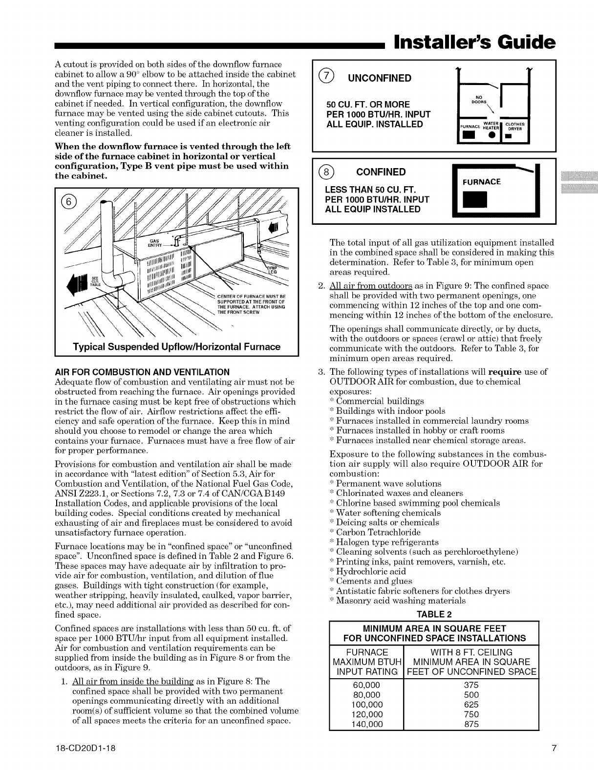
A cutout is provided on both sides of the downflow furnace
cabinet to allow a 90 ° elbow to be attached inside the cabinet
and the vent piping to connect there. In horizontal, the
downflow furnace may be vented through the top of the
cabinet if needed. In vertical configuration, the downflow
furnace may be vented using the side cabinet cutouts. This
venting configuration could be used if an electronic air
cleaner is installed.
When the downflow furnace is vented through the left
side of the furnace cabinet in horizontal or vertical
configuration, Type B vent pipe must be used within
the cabinet.
Typical Suspended Upflow/Horizontal Furnace
AIR FOR COMBUSTION AND VENTILATION
Adequate flow of combustion and ventilating air must not be
obstructed from reaching the furnace. Air openings provided
in the furnace casing must be kept free of obstructions which
restrict the flow of air. Airflow restrictions affect the effi-
ciency and safe operation of the furnace. Keep this in mind
should you choose to remodel or change the area which
contains your furnace. Furnaces must have a free flow of air
for proper performance.
Provisions for combustion and ventilation air shall be made
in accordance with "latest edition" of Section 5.3, Air for
Combustion and Ventilation, of the National Fuel Gas Code,
ANSI Z223.1, or Sections 7.2, 7.3 or 7.4 of CAN/CGA B149
Installation Codes, and applicable provisions of the local
building codes. Special conditions created by mechanical
exhausting of air and fireplaces must be considered to avoid
unsatisfactory furnace operation.
Furnace locations may be in "confined space" or "unconfined
space". Unconfined space is defined in Table 2 and Figure 6.
These spaces may have adequate air by infiltration to pro-
vide air for combustion, ventilation, and dilution of flue
gases. Buildings with tight construction (for example,
weather stripping, heavily insulated, caulked, vapor barrier,
etc.), may need additional air provided as described for con-
fined space.
Confined spaces are installations with less than 50 cu. ft. of
space per 1000 BTU/hr input from all equipment installed.
Air for combustion and ventilation requirements can be
supplied from inside the building as in Figure 8 or from the
outdoors, as in Figure 9.
1. All air from inside the building as in Figure 8: The
confined space shall be provided with two permanent
openings communicating directly with an additional
room(s) of sufficient volume so that the combined volume
of all spaces meets the criteria for an unconfined space.
Installer's Guide
UNCONFINED
50 CU. FT. OR MORE
PER 1000 BTU/HR. INPUT
ALL EQUIP. INSTALLED
CONFINED I
LESS THAN 50 CU. FT.
PER 1000 BTU/HR. INPUT
ALL EQUIP INSTALLED
FURNACE
2.
3.
The total input of all gas utilization equipment installed
in the combined space shall be considered in malting this
determination. Refer to Table 3, for minimum open
areas required.
All air from outdoors as in Figure 9: The confined space
shall be provided with two permanent openings, one
commencing within 12 inches of the top and one com-
mencing within 12 inches of the bottom of the enclosure.
The openings shall communicate directly, or by ducts,
with the outdoors or spaces (crawl or attic) that freely
communicate with the outdoors. Refer to Table 3, for
minimum open areas required.
The following types of installations will require use of
OUTDOOR AIR for combustion, due to chemical
exposures:
* Commercial buildings
* Buildings with indoor pools
* Furnaces installed in commercial laundry rooms
* Furnaces installed in hobby or craft rooms
* Furnaces installed near chemical storage areas.
Exposure to the following substances in the combus-
tion air supply will also require OUTDOOR AIR for
combustion:
* Permanent wave solutions
* Chlorinated waxes and cleaners
* Chlorine based swimming pool chemicals
* Water softening chemicals
* Deicing salts or chemicals
* Carbon Tetrachloride
* Halogen type refrigerants
* Cleaning solvents (such as perchloroethylene)
* Printing inks, paint removers, varnish, etc.
* Hydrochloric acid
* Cements and glues
* Antistatic fabric softeners for clothes dryers
* Masonry acid washing materials
TABLE 2
MINIMUM AREA IN SQUARE FEET
FOR UNCONFINED SPACE INSTALLATIONS
FURNACE
MAXIMUM BTUH
INPUT RATING
60,000
80,000
100,000
120,000
140,000
WITH 8 FT. CEILING
MINIMUM AREA IN SQUARE
FEET OF UNCONFINED SPACE
375
500
625
750
875
18-CD20D1-18 7
iiiiiiiiiiii
Installer's Guide
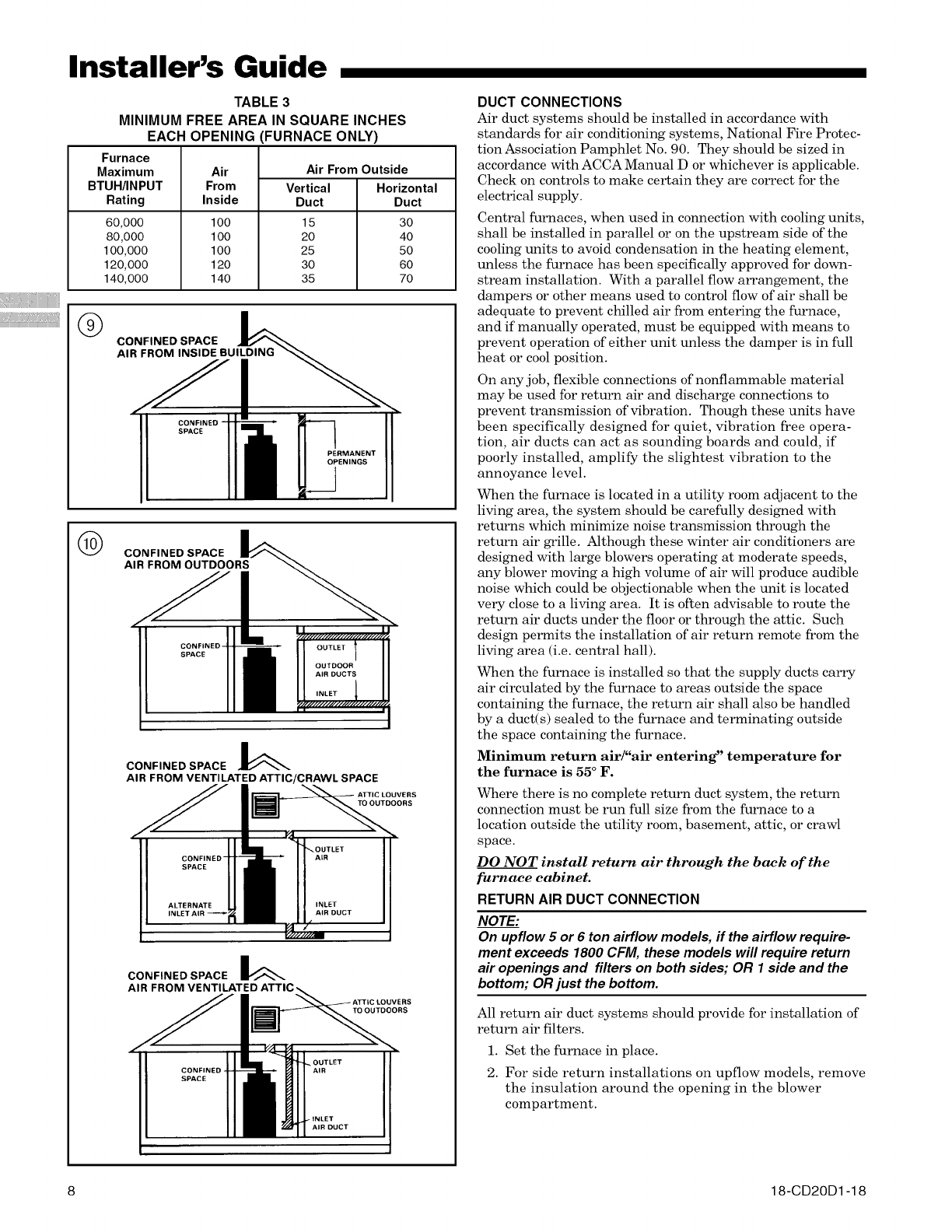
TABLE 3
MINIMUM FREE AREA IN SQUARE INCHES
EACH OPENING
Furnace
Maximum
BTUH/INPUT
Rating
60,000
80,000
100,000
120,000
140,000
Air
From
Inside
FURNACE ONLY)
Air From Outside
Vertical Horizontal
Duct Duct
100 15 30
100 20 40
100 25 50
120 30 60
140 35 70
®CONFINED SPACE k
AI_UlLDING _
PERMANENT
OPENINGS
(_ CONFINED SPACE
AIR FROM OUTDOORS
CONFINED-
SPACE
CONFINED SPACE k
AIR FROM VENTILATED ATTIC/CRAWL SPACE
AIR
INLET
AtR DUCT
DUCT CONNECTIONS
Air duct systems should be installed in accordance with
standards for air conditioning systems, National Fire Protec-
tion Association Pamphlet No. 90. They should be sized in
accordance with ACCA Manual D or whichever is applicable.
Check on controls to make certain they are correct for the
electrical supply.
Central furnaces, when used in connection with cooling units,
shall be installed in parallel or on the upstream side of the
cooling units to avoid condensation in the heating element,
unless the furnace has been specifically approved for down-
stream installation. With a parallel flow arrangement, the
dampers or other means used to control flow of air shall be
adequate to prevent chilled air from entering the furnace,
and if manually operated, must be equipped with means to
prevent operation of either unit unless the damper is in full
heat or cool position.
On any job, flexible connections of nonflammable material
may be used for return air and discharge connections to
prevent transmission of vibration. Though these units have
been specifically designed for quiet, vibration free opera-
tion, air ducts can act as sounding boards and could, if
poorly installed, amplify the slightest vibration to the
annoyance level.
When the furnace is located in a utility room adjacent to the
living area, the system should be carefully designed with
returns which minimize noise transmission through the
return air grille. Although these winter air conditioners are
designed with large blowers operating at moderate speeds,
any blower moving a high volume of air will produce audible
noise which could be objectionable when the unit is located
very close to a living area. It is often advisable to route the
return air ducts under the floor or through the attic. Such
design permits the installation of air return remote from the
living area (i.e. central hall).
When the furnace is installed so that the supply ducts carry
air circulated by the furnace to areas outside the space
containing the furnace, the return air shall also be handled
by a duct(s) sealed to the furnace and terminating outside
the space containing the furnace.
Minimum return air/"air entering" temperature for
the furnace is 55 ° F.
Where there is no complete return duct system, the return
connection must be run full size from the furnace to a
location outside the utility room, basement, attic, or crawl
space.
DO NOT install return air through the back of the
furnace cabinet.
RETURN AIR DUCT CONNECTION
NOTE:
On upflow 5 or 6 ton airflow models, if the airflow require-
ment exceeds 1800 CFM, these models will require return
air openings and filters on both sides; OR 1 side and the
bottom; OR just the bottom.
All return air duct systems should provide for installation of
return air filters.
1. Set the furnace in place.
2. For side return installations on upflow models, remove
the insulation around the opening in the blower
compartment.
8 18-CD20D 1-18

3. The side panels on upflow furnaces include locating
notches which may be used as guides for cutting an
opening for return air. Refer to Figure 12 and the
outline drawing on page 4 for duct connection dimen-
sions for various furnaces.
4. If a 3/4" flange is to be used for attaching the air inlet
duct, add to cut where indicated by solid lines in
Figure 12. Cut corners diagonally and bend outward to
form flange.
5. If flanges are not required, and a filter frame is installed,
cut along knockout guidelines.
6. Upflow Furnaces: a filter rack is factory supplied for
bottom or side return. Use the filter rack on either side
or on the bottom if the filter is to be used within the
furnace cabinet.
When the upflow furnace is installed in the horizontal
right or left application and a return duct is attached to
the top side as shown in Figure 11, remove the filter
from the furnace and install in a remote location.
Do not install the filter in the return duct directly above the
furnace in horizontal applications. Install the filter remotely.
Installing the filter directly above the furnace in horizontal
applications may cause property damage, serious injury or
death.
TO PREVENT INJURY OR DEATH DUE TO CONTACT
WITH MOVING PARTS, TURN THE POWER TO THE
FURNACE OFF BEFORE SERVICING FILTERS.
Do not install the filter in the return duct directly above
the furnace in horizontal applications.
When the upflow furnace is installed in the horizontal
right or left application and a close coupled (less than
36") return duct is attached to the bottom side of the
furnace as shown in Figure 11, securely attach a 1/2"
mesh metal hardware cloth protective screen to the
inside bottom of the filter grill to prevent personal
injury from contacting moving parts when reach-
ing into the return opening to replace the filter.
REMOVE FILTER FROM UPFLOW
FURNACE WHEN RETURN DUCT IS
ATTACHED TO FURNACE TOP SIDE
(HORIZONTAL LEFT OR RIGHT
APPLICATIONS) AS SHOWN.
DDDBBHIIIDDHHB_
IIDIDIt!IB1111
IBBBBDIIIBDDDD
BDDBIIIII11111
IIIIIIIIIIII II
IIIIIIIIIIII I I +
Close coupled (less than 36")
return (filter directly beneath bottom
side return) not recommended due to
noise considerations. If used, securely
attach 1/2" mesh metal hardware cloth
protective screen to the inside bottom of
filter grill.
Installer's Guide
7.
Close coupled (less than 36") return (filter directly
beneath bottom side return) is not recommended due to
noise considerations.
Downflow Furnaces: Brackets are factory supplied to
mount filters in the return air duct work.
Connect the duct work to the furnace. See Outline
Drawing for supply and return duct size and location.
Flexible duct connectors are recommended to connect
both supply and return air ducts to the furnace.
If only the front of the furnace is accessible, it is recom-
mended that both supply and return air plenums are
removable.
8. When replacing a furnace, old duct work should be
cleaned out. Thin cloths should be placed over the
registers and the furnace fan should be run for 10 min-
utes. Don't forget to remove the cloths before you start
the furnace.
RETURN AIR FILTERS
TYPICAL UPFLOW RETURN AIR FILTER INSTALLATIONS
Filters are factory supplied for these furnaces. These fur-
naces require high velocity type air filters. The filters may be
located within the furnace blower compartment for UPFLOW
furnaces in either a BOTTOM or SIDE (left side or right side)
return air inlet. Some filters may need to be trimmed for
side or bottom filter use.
NOTE:
On upflow 5 or 6 ton airflow models, if the airflow require-
ment exceeds 1800 CFM, these models will require return
air openings and filters on both sides; OR 1 side and the
bottom; OR just the bottom.
@
LOCATING F" I/
NOTCHES *
PROVIDED I
FOR SIDE /
RETURN ,,,L,,,/ I
CUTOUT ,4_ _i:_/
•SEE OUTLINE DRAWING
CUT OUT
FOR
SIDE
FILTER
_RuOr N:e
The upflow furnace blower door has a hinge at the bottom
which allows the door to tilt forward for filter replacement
without the door being removed. The furnace filter in the
bottom or side configuration can be removed by simply
turning the two latches on the blower door and tilting the
door forward.
The filter rails are spring loaded for automatic adjustment to
allow standard size, locally obtainable replacement filters.
The filter rack itself slides to adjust to the required width
needed for bottom or side return.
!iiii!ii!!i!!i!!i!!i!!i!!i!!i!!i!!i!!i!!!_iii
18-CD20D1-18 9
iiiiiiiiiiii
Installer's Guide
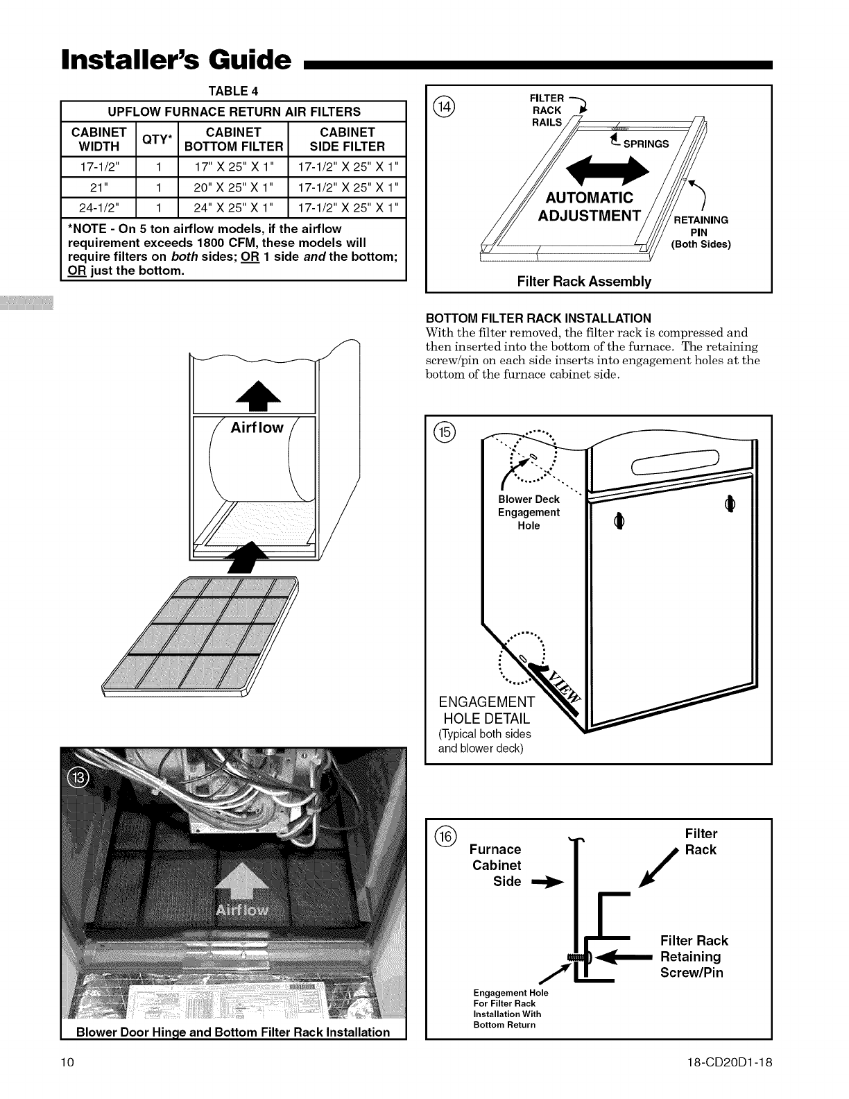
TABLE 4
UPFLOW FURNACE RETURN AIR FILTERS
CABINET CABINET
QTY*
WIDTH BOTTOM FILTER
17-1/2" 1 17" X 25" X 1"
21" 1 20" X 25" X 1"
24-1/2" 1 24" X 25" X 1"
CABINET
SIDE FILTER
17-1/2" X 25" X 1"
17-1/2" X 25" X 1"
17-1/2" X 25" X 1"
*NOTE -On 5 ton airflow models, if the airflow
requirement exceeds 1800 CFM, these models will
require filters on both sides; OR 1 side and the bottom;
OR just the bottom.
(_ FILTER
RACK "-_
RETAINING
PIN
(Both Sides)
Filter Rack Assembly
BOTTOM FILTER RACK INSTALLATION
With the filter removed, the filter rack is compressed and
then inserted into the bottom of the furnace. The retaining
screw/pin on each side inserts into engagement holes at the
bottom of the furnace cabinet side.
Blower Door Hin(
10
and Bottom Filter Rack Installation
®
.,-.% ,"
Blower Deck
Engagement
Hole
%,,=,
ENGAGEMENT
HOLE DETAIL
(Typicalboth sides
and blower deck)
®Furnace
Cabinet
Side
Engagement Hole
For Filter Rack
Installation With
Bottom Return
Filter
Rack
Filter Rack
Retaining
Screw/Pin
18-CD20D 1-18

Cabinet Width Left Side Bottom Right Side
17,5 X X X
21 X X X
24,5 X X X
1, UD060C/R936K0 has 10x7 blower which requires use of alternate
filter clips for left side filter, "K1" and later use the filter rack,
2, Remove bottom front channel to install or reposition filter rack,
X - All Models
FILTER RACK INSTALLATION FOR SIDE RETURN AIR
ON UPFLOW FURNACES (LEFT OR RIGHT)
If side air return is desired, it is necessary to move the filter
rack from the bottom of the furnace and reinstall it on the
side. The following instructions should be used:
a. Open or remove the blower door.
b. Remove the filter.
c. Compress the filter rack to disengage the retaining
pins/screws from the furnace sides and slide the filter
rack out.
d. Leave the bottom panel in place.
e. After the side cutout is made following the directions
in the "Return Air Duct Connections" section on
pages 8 and 9; compress the filter rack and reinstall
in the side of the furnace. Confirm that the upper
retaining pin/screw locks into the engagement hole in
the blower deck and the lower pin/screw rests against
the side of the bottom panel. See Figures 14 - 19.
f. Reinstall the furnace filter on the side.
®BOTTOM ENGAGEMENT
Filter Rack
Retaining
Furnace . m Screw/Pin Filter
Cabinet ...,,]_1
/Rack
Side !_ t
Engagement HoleFor Filter Rack
Installation With
Bottom Return
Bottom Panel
®
BLOWER
DECK
Furnace
Cabinet
Side
Engagement Hole Furnace
For Filter Rack Blower
Installation With
Side Return Deck
Retaining Rack
Screw/Pin Assembly
Installer's Guide
BOTTOM
PANEL
INSTALLED
Typical Upflow Left Side Return Filter Rack Installation
Typical Upflow Right Side Return Filter Rack Installation
Typical Filters of Upflow in Horizontal
18-CD20D1-18 11
Installer's Guide
RETURN AIR FILTERS FOR UPFLOW FURNACE
IN HORIZONTAL CONFIGURATION
When the Upflow Furnace is installed in the horizontal
configuration, the return air filters must be installed exterior
to the cabinet. Remote filter grilles may be used for home-
owner convenience or the filters may be installed in the duct
work upstream of the furnace. See Figure 21.
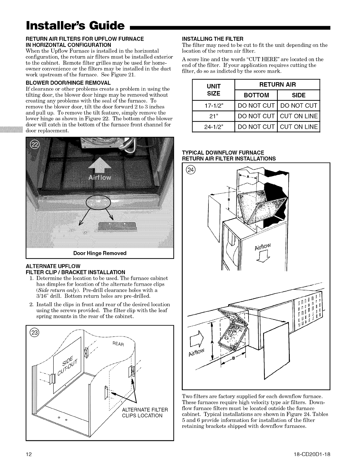
BLOWER DOOR/HINGE REMOVAL
If clearance or other problems create a problem in using the
tilting door, the blower door hinge may be removed without
creating any problems with the seal of the furnace. To
remove the blower door, tilt the door forward 2 to 3 inches
and pull up. To remove the tilt feature, simply remove the
lower hinge as shown in Figure 22. The bottom of the blower
door will catch in the bottom of the furnace front channel for
door replacement.
INSTALLING THE FILTER
The filter may need to be cut to fit the unit depending on the
location of the return air filter.
A score line and the words "CUT HERE" are located on the
end of the filter. If your application requires cutting the
filter, do so as indicted by the score mark.
UNIT
SIZE
17-1/2"
21"
24-1/2"
RETURN AIR
BOTTOM SIDE
DO NOT CUT DO NOT CUT
DO NOT CUT CUT ON LINE
DO NOT CUT CUT ON LINE
Door Hinge Removed
ALTERNATE UPFLOW
FILTER CLIP /BRACKET INSTALLATION
1. Determine the location to be used. The furnace cabinet
has dimples for location of the alternate furnace clips
(Side return only). Pre-drill clearance holes with a
3/16" drill. Bottom return holes are pre-drilled.
2. Install the clips in front and rear of the desired location
using the screws provided. The filter clip with the leaf
spring mounts in the rear of the cabinet.
ALTERNATE FILTER
CLIPS LOCATION
TYPICAL DOWNFLOW FURNACE
RETURN AIR FILTER INSTALLATIONS
@
Two filters are factory supplied for each downflow furnace.
These furnaces require high velocity type air filters. Down-
flow furnace filters must be located outside the furnace
cabinet. Typical installations are shown in Figure 24. Tables
5 and 6 provide information for installation of the filter
retaining brackets shipped with downflow furnaces.
12 18-CD20D 1-18

Installer's Guide
TABLE 5
CABINET FILTER FILTER BRACKET
WIDTH SIZE LOCATION *
17-1/2" 2 -16X20X1 14-3/8"
21" 2- 16X20X1 13-1/8"
24-1/2" 2 - 16X20X1 11-5/8"
• Location dimension is from end of duct to the screw holes for the bracket.
TABLE 6
RETURN FILTER ACCESS FILTER ACCESS
CABINET DUCT OPENING - OPENING -
WIDTH WIDTH DIMENSION"A" DIMENSION"B"
17-1/2" 16-1/4" 15" 14"
21" 19-3/4" 19-1/2" 14"
24-1/2" 23-1/4" 22" 14"
GENERAL VENTING INSTRUCTIONS
VENT PIPING
These furnaces have been classified as Fan-Assisted Combus-
tion System, Category I furnaces under the "latest edition"
provisions of ANSI Z21.47 and CAN/CGA 2.3 standards.
Category I furnaces operate with a non-positive vent static
pressure and with a flue loss of not less than 17 percent.
NOTE:
If desired, a side waft termination can be accomplished
through the use of an "add-on" draft inducer. The inducer
must be installed according to the inducer manufacturer's
instructions. Set the barometric pressure relief to achieve
-0.02 inch water column.
NOTE: When the downflow furnace is vented through the
left side of the furnace cabinet using the provided cutout,
Type B vent piping must be used.
The furnace shaft be connected to a factory built chimney
or vent complying with a recognized standard, or a ma-
sonry or concrete chimney lined with a lining material
acceptable to the authority having jurisdiction.
CARBON MONOXIDE POISONING HAZARD
Failure to follow the steps outlined below for each
appliance connected to the venting system being
placed into operation could result in carbon monoxide
poisoning or death.
The following steps shall be followed for each appliance
connected to the venting system being placed into
operation, while all other appliances connected to the
venting system are not in operation:
1. Seal any unused openings in the venting system.
2. Inspect the venting system for proper size and
horizontal pitch, as required in the National Fuel Gas
Code, ANSI Z223.1/NFPA 54 or the CAN/CGA B149
Installation Codes and these instructions. Determine
that there is no blockage or restriction, leakage,
corrosion and other deficiencies which could cause an
unsafe condition.
3. As far as practical, close all building doors and
windows and all doors between the space in which the
appliance(s) connected to the venting system are
located and other spaces of the building.
4. Close fireplace dampers.
5. Turn on clothes dryers and any appliance not
connected to the venting system. Turn on any exhaust
fans, such as range hoods and bathroom exhausts, so
they are operating at maximum speed. Do not operate
a summer exhaust fan.
6. Follow the lighting instructions. Place the appliance
being inspected into operation. Adjust the thermostat
so appliance is operating continuously.
7. If improper venting is observed during any of the above
tests, the venting system must be corrected in
accordance with the National Fuel Gas Code,
ANSI Z221.1/NFPA 54 and/or CAN/CGA B149
Installation Codes.
8. After it has been determined that each appliance
connected to the venting system properly vents where
tested as outlined above, return doors, windows,
exhaust fans, fireplace dampers and any other gas-fired
burning appliance to their previous conditions of use.
Furnace venting into an unlined masonry chimney or
concrete chimney is prohibited. Failure to follow this
warning could result in property damage, personal injury,
or death.
VENTING INTO A MASONRY CHIMNEY
If the chimney is oversized, the liner is inadequate, or flue-
gas condensation is a problem in your area, consider using
the chimney as a pathway or chase for type "B" vent or flex-
ible vent liner. If flexible liner material is used, size the vent
using the "B" vent tables, then reduce the maximum capacity
by 20% (multiply 0.80 times the maximum capacity).
Masonry Chimney Kit BAYVENT800B may be used with
these furnaces (Upflow model furnaces only) to allow
venting into a masonry chimney. Refer to the BAYVENT800B
Installer's Guide for application requirements.
Internal Masonry Chimneys
Venting of fan assisted appliances into a lined, internal
masonry chimney is allowed only if it is common vented with
at least one natural draft appliance; OR, if the chimney is
lined with type "B", double wall vent or suitable flexible liner
material (See Table 7).
The chimney liner must be thoroughly inspected to insure
no cracks or other potential areas for flue gas leaks are
present in the liner. Liner leaks will result in early deteriora-
tion of the chimney.
Failure to follow this warning could result in carbon monox-
ide poisoning or death.
18-CD20D1-18 13

Installer's Guide
NOTE:
The following section does not apply if BA YVENTSOOB
(Masonry Chimney Vent Kit) is used. All instructions with
the kit must be followed.
TABLE 7
MASONRY CHIMNEY VENTING
Type Furnace
Single Fan
Assist
Fan Assist
+
Fan Assist
Fan Assist
+
Natural
Tile Lined Chimney
Internal External
No No
No No
Yes No
Chimney Lining
Flexible
"B" Vent Metal Liner
Yes Yes*
Yes*
Yes*
Yes
Yes
Flexible chimney liner size is determined by using the type "B" vent size for
the available BTUH input, then reducing the maximum capacity by 20%
(multiply maximum capacity times 0.80). The minimum capacity is the same
as shown in the "B" vent tables.
EXTERNAL MASONRY CHIMNEY
Venting of fan assisted appliances into external chimneys
(one or more walls exposed to outdoor temperatures), re-
quires the chimney be lined with type "B', double wall vent
or suitable flexible chimney liner material. This applies in
all combinations of common venting as well as for fan
assisted appliances vented alone.
The following installation practices are recommended to
minimize corrosion caused by condensation of flue products
in the furnace and flue gas system.
CARBON MONOXIDE POISONING HAZARD
Failure to follow the installation instructions for the venting
system being placed into operation could result in carbon
monoxide poisoning or death.
1. Avoid an excessive number of bends.
2. Horizontal runs should pitch upward at least 1/4" per foot.
3. Horizontal runs should be as short as possible.
4. All vent pipe or connectors should be securely supported
and must be inserted into, but not beyond the inside wall
at the chimney vent.
5. When vent connections must pass through walls or
partitions of combustible material, a thimble must be
used and installed according to local codes.
6. Vent pipe through the roof should be extended to a
height determined by National Fuel Gas Code or local
codes. It should be capped properly to prevent rain
water from entering the vent. Roof exit should be
waterproofed.
7. Use type "B" double wall vent when vent pipe is routed
through cool spaces (below 60 ° F.).
8. Where long periods of airflow are desired for comfort,
use long fan cycles instead of continuous airflow.
9. Apply other good venting practices as stated in the
venting section of the National Fuel Gas Code
ANSI Z223.1 "latest edition".
10. Vent connectors serving appliance vented by
natural draft or non-positive pressure shall not be
connected into any portion of a mechanized draft
system operating under positive pressure.
®
TABLE 8
GAS VENTTERMINATION
ROOF PITCH
FLAT TO 7/12
OVER 7/12 TO 8/12
OVER 8/12 TO 9/12
OVER 9/12 TO 10/12
OVER 10/12 TO 11/12
OVER 11/12 TO 12/12
OVER 12/12 TO 14/12
OVER 14/12 TO 16/12
OVER 16/12 TO 18/12
OVER 18/12 TO 20/12
OVER 20/12 TO 22/12
MINIMUM HEIGHT
1.0 FEET *
1.5 FEET
2.0 FEET
2.5 FEET
3,25 FEET
4.0 FEET
5.0 FEET
6.0 FEET
7.0 FEET
7.5 FEET
8.0 FEET
THIS REQUIREMENT COVERS MOST INSTALLATIONS
LISTED
CAP
VERTICAL W.,_l
OPENING II
THE VENT TERMINATION SHOULD NOT BE
LESS THAN 8 FT FROM AVERTICAL WALL
11. Horizontal pipe runs must be supported by hangers,
straps or other suitable material in intervals at a
minimum of every 3 feet of pipe.
12. A furnace shall not be connected to a chimney or flue
serving a separate appliance designed to burn solid fuel.
13. The flow area of the largest section of vertical vent or
chimney shall not exceed 7 times the smallest listed
appliance categorized vent area, flue collar area, or draft
hood outlet area unless designed in accordance with
approved engineering methods.
Maximum Vent or Tile =_:(D*)---_2X 7
Lined Chimney Flow Area 4
*Draf'_hood outlet diameter, flue collar' diameter, or' listed appliance categorized vent
diameter.
The cabinet must have an uninterrupted or unbroken ground
according to National Electrical Code, ANSI/NFPA 70 -
"latest edition" and Canadian Electrical Code, CSA C22.1 or
local codes to minimize personal injury if an electrical fault
should occur. A failure to follow this warning could result in
an electrical shock, fire, injury, or death.
The integrated furnace control is polarity sensitive. The hot
leg of the 115 VAC power must be connected to the BLACK
field lead.
To prevent injury or death due to electrical shock or contact
with moving parts, lock unit disconnect switch in the open
position before servicing the unit. Failure to follow this
warning could result in electrical shock, personal injury, or
death.
14 18-CD20D1-18

Installer's Guide
ELECTRICAL CONNECTIONS
Make wiring connections to the unit as indicated on enclosed
wiring diagram. As with all gas appliances using electrical
power, this furnace shall be connected into a permanently live
electric circuit. It is recommended that it be provided with a
separate "circuit protection device" electric circuit. The
furnace must be electrically grounded in accordance with
local codes or in the absence of local codes with the National
Electrical Code, ANSI/NFPA 70 "latest edition" or Cana-
dian Electrical Code, CSA C22.1, if an external electrical
source is utilized.
All field supplied wiring must conform with the temperature
limitation for Type T wire [63 ° F (35 ° C)], when installed in
accordance with these instructions and wiring diagrams
supplied with the furnace. A disconnecting means must be
located within sight from, and readily accessible to, the
furnace.
Refer to the SERVICE FACTS literature for unit wiring
diagrams in addition to the diagram inside the blower door.
T'STAT
[]
FIELD WIRING DIAGRAM FOR VARIABLE SPEED 2 STAGE FURNACE
1 STAGE HEATING
SEE
] NOTE6
USING
VARIABLE SPEED
2-STAGE FURNACE
[]
[]
] W14JUMPER
SEE NOTE11
[]
r_-., SEE
I_NOTE 9
tT1/
A 1 STAGE HEATING THERMOSTAT
NO COOLING
1. Be sure power aglees with equipment nameplates.
2. Low voltage (24 volt wiling) to be No. 18 A.W.G. min.
3. Grounding of equipment must comply with local codes.
4. Set thermostat heat anticipatol per unit wiling diaglam.
5. These leads provide 115V. power for connection of electronic
air cleaner and humidifier MAX. load 1.0 amps each.
6. When a single stage heating thermostat without fan switch
is used, no wiring on "G" terminal is used.
7. Wl and W2 must be jumpered together lot proper operation.
Second stage heat wiR begin 10 minutes aftel fhst stage.
8. Set dip switches with power off per installation instructions
to set airflow and indoor fan off delays.
9. Continuous fan airflow can be increased by adding this jumper.
10. This whe is only lot theimostats lequMng connection to
transformer common terminal.
11. Optional humidistat is to be connected between R and BK. Factory installed jumper R
to BK on the circuit board must be cut if optional humidistat is used. The jumper must
also be cut when applying an airflow command signal to the BK input such as with the
variable speed single-zone and multi-zone system contiolleis. On single speed cooling
only/non-heat pump systems, jumper Y to O for propel operation of the delay profiles
and the humidistat. For two compressol st two speed systems, jumper YLo to O.
FIELD ADDED JUMPER G ou rl S
Wl TOW2. _ SCREW
[_ J_ 2ND STAGEWILL FIRE ]_ FU 1:2N A C E
L_ L_U,, _J ................. ,I _ _K JJNCTIO
I_ I_ I _ox
LH BK
[] ........... +,1
SEE 60 HZ., POWER _ I
NOTE 10 SUPPLY PER I I
[] [] ..........t+
I I r /I_H / I
]NTER )VP NET W[R]NG ...... jWH , I I / I
NOTES I_K --_--_=Ln .... I
24 '/. mk_ F]ELIU
IIL]NE 'i'J i'N'JR[q"; EACSEE [_ WH __ [ I _ I
24 g. "k FAtZTE) RY ..... ]_BK _ _
-- L ] N E v'. _" W I Y¢[ N ,_] From Dwg. B342027 Rev. 0
J
T'STAT
[]
[]
[]
[]
[]
FIELD WIRING DIAGRAM FOR VARIABLE SPEED 2 STAGE FURNACE
2 STAGE HEATING
USING A 2 STAGE HEATING THERMOSTAT
NO COOLING
VARIABLE SPEED
B-STAGE FURNACE I.
-- 2.
3,
[] t
[] 6,
] WI4JUMPER
SEE NOTE 9
[]
F_.,
i
i_ SEE
]J NOTE 7
[]
[]
SEE
NOTE 6 []
Be sure power agrees with equipment nameplates.
Low voltage (24 volt wiring) to be No. 18 A,W,G, rain,
Grounding of equipment must comply with local codes,
Set thermostat heat anticipator per unit wiring diagram,
These leads provide 115M power for connection of electronic
air cleaner and humidifier MAX, load 1.0 amps each,
This wire is only for thermostats requiring connection to
transformer common terminal,
7, Continuous fan airflow can be increased by adding this jumper,
8, Set dip switches with power off per installation instructions
to set airflow and indoor fan off delays,
9, Optional humidistat is to be connected between R and BK, Factory
installed jumper R to BK on the circuit board must be cut if optional
humidistat is used, The jumper must also be cut when applying an airflow
command signal to the BK input such as with the variable speed single-zone
and multbzone system controllers, On single speed cooling only/non-heat pump
systems, jumper Y to O for proper operation of the delay profiles and the humidistat,
For two compressor or two speed systems, jumper YLo to O
I I
INTER CUdPSNENT ",t71R[N _
P4 V "_L FIELD
II [_ iNE" ,/. ]k ',B,'[_i IN G
24 ,/. m(> FA T'F_Y
-- L ]NE ,/.J 'TR[R IN G From Dwg. B342025 Rev. 0
18-CD20D1-18 15
Installer's Guide
OUTDOOR UNIT
(NO TRANSF©RMER)
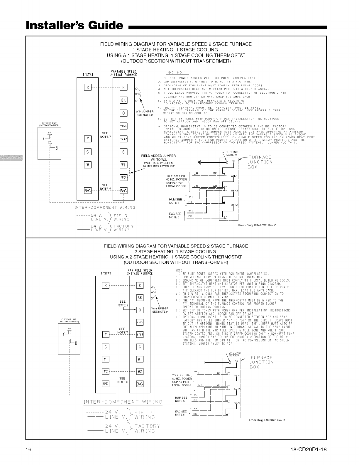
FIELD WIRING DIAGRAM FOR VARIABLE SPEED 2 STAGE FURNACE
1 STAGE HEATING, 1 STAGE COOLING
USING A 1 STAGE HEATING, 1 STAGE COOLING THERMOSTAT
(OUTDOOR SECTION WITHOUT TRANSFORMER)
T"STAT
[]
VARIABLE SPEED
?-STAGE FURNACE
[] o-,
[]
[]
[]
SEE
D NOTE7[]
W14JUMPER
SEENOTE9
NOTES "
I BE SURE POWER AGREES WITH EQUIPMENT NAMEPLATE[S)
2 LOW VOLTAGE(24 v WIRING) TO BE O 18 A w G MIN
5 GRO NDING OF EQUISMENT MUST COMPLY WITH LOCAL CODES
4 SET THERMOSTAT HEAT ANTICIPATOR PER NIT WIRING DIAGRAM
5 THESE LEADS PROVIDE 115 V POWER FOR CONNECTIO OF ELECTRONIC AIR
CLEANER AND HUMIDIFIER MAX LOAD I O AMPS EACH
6 THIS WIRE IS ONLY FOR THERMOSTATS REO IRING
CO ECTION TO TRANSFORMER COMMO TERMINAL
7 THE "Y" TERMINAL FROM THE THERMOSTAT MUST BE WIRED
TO THE "Y" TERMINAL OF THE FUR ACE CONTROL FOR PROPER BLOWER
OPERATION DURING COOLING
8 SET DIP SWITCHES WITH POWER OFF PER INSTALLATION INSTRUCTIONS
TO SET AIRFLOW AND INDOOR FAN OFF DELAYS
9 OPTIONAL HUMIDISTAT IS TO BE CONNECTED BETWEEN R AND BK FACTORY
INSTALLED JUMPER R TO BK ON THE CIRCUIT BOARD MUST BE CUT IF OPTIONAL
HUMIDISTAT IS USED THE JUMPER MUST ALSO BE CUT WHEN APPLYING AN AIRFLOW
COMMAND SIGNAL TO THE BH INPUT SUCH AS WITH THE VARIABLE SPEED,SINGLE ZONE
AND MULTI ZONE SYSTEM CONTROLLERS, ON SINGLE SPEED COOLING ONLY/NON HEAT PUMP
SYSTEMS, JUMPER Y TO O FOR PROPER OPERATION OF THE BELAY PROFILES AND THE
HUMIDISTAT FOR TWO COMPRESSOR OR TWO SPEED SYSTEMS, JUMPER YLO TO O
] [] VGROUND
FIELD ADDED JUMPER SC REW
_-_ FURNACE
Wl TO W2. BK
_ 2ND STAGE WILL FIRE II I J U N C T ] 0 N
L_J, 10 MINUTES AFTER lS1_ I / I ClcqV
L,._ ,I-- ,
I'_'_'-I J TO 115V ' P"., [--LH B--_I<"'1--1-[_ .... I
"l.Ld BB.Z.,POWERJ I _ ,
SUPPLY PER II I
SEE LOCALCODES 1 LN WH S J
.w./ / ,_,
; HUM SEE J "" .--I JI S I
• NOTE5 L} BK __Jr ___ _ ,I
INTER COM_OkEIxT W]_]NG I I h'B!
4 _ EAC SEE [- WH -- J I i,,__1 Ii
2 V. % FIELD NOTE5 _ Sl< l_q I
----LI E V._W]RING L" _--_
2 4 V. _ F A {" • 0 R Y From Dwg. B342022 Rev. 0
--LINE V.._ WIRING
OUTDOORUNIT
(NOTRANSFORMEf_)
FIELD WIRING DIAGRAM FOR VARIABLE SPEED 2 STAGE FURNACE
2 STAGE HEATING, 1 STAGE COOLING
USING A 2 STAGE HEATING, 1 STAGE COOLING THERMOSTAT
(OUTDOOR SECTION WITHOUT TRANSFORMER)
VARIABLE SPEED
T'STAT ?-STAGE FURNACE
[] [] o.,
W141
SEE []
NOTE9
L .__/F_I W14JUMPER
SEE NGTE9
[]
SEE
[] []
[] []
[] []
[] []
SEE
i
L •
INTER COk,4POqENT ',,,,I,ilRING
-w
? 'v'. \ FIELD
-- -- . ',,/'/I IN',_
L ] I' E ,r
24 V. '_ FA,,'}•O _Y
--LINE ',,". _'v'v'IFINO
NOTE:
I BE SURE POWER AGREES WITH EQUIPMENT NAMEPLATE(S}
R LOW VOLTAGE (R4V WIRING) TO BE NO IBAWG MIN
3 GROUNDING OF EQUIPMENT MUST COMPLY WITH LOCAL BUILDING CODES
4 SET THERMOSTAT HEAT ANTICIPATOR PER UNIT WIRING DIAGRAM
5 THESE LEADS PROVIDE llSV POWER FOR CONNECTION OF ELECTRONIC
AIR CLEANER AND HUMIDIFIER MAX LOAD I0 AMPS EACH
6 THIS WIRE IS ONLY FOR THERMOSTATS REQUIRING CONNECTION TO
TRANSFORMER COMMON TERMINAL
7 THE "Y" TERMINAL FROM THE THERMOSTAT MUST BE WIRED TO THE
"Y" TERMIRAL OF THE FURNACE CONTROL FOR PROPER BLOWER
OPERATION DURING COOLIRG
8 SET DIP SWITCHES WITH POWER OFF PER INSTALLATION INSTRUCTIONS
TO SET AIRFLOW AND INDOOR FAN OFF DELAYS
9) OPTIONAL HUMIDISTAT IS TO BE CONNECTED BETWEEN "R" AND "BK"
FACTORY IRSTALLED JUMPER "R" TO "BH" ON THE CIRCUIT BOARD MUST
BE CUT IF OPTIONAL HUMIDISTAT IS USED THE JUMPER MUST ALSO BE
CUT WHEN APPLYING AN AIRFLOW COMMAND SIGNAL TO THE "BN" INPUT
SUCH AS WITH THE VARIABLE SPEED SINGLE ZORE AND MULTI ZONE
SYSTEM CONTROLERS ON SINGLE SPEED COOLING ONLY /NON HEAT PUMP
SYSTEMS, JUMPER "Y" TO "0" FOR PROPER OPERATION OF THE DELAY
PROFILES AND THE HUMIDISTAT FOR TWO COMPRESSOR OR TWO SPEED
SYSTEMS, JUMPER "YLO" TO "0"
From Dwg B342020 Rev, 0
16 18-CD20D 1-18
Installer's Guide
OUTDOOR UNIT NO 1
(NO TRANSFORMER)
SEE NOTE 3
i
i
OUTDOOR UNIT NO 2 I
(NO TRANSFORMER} I
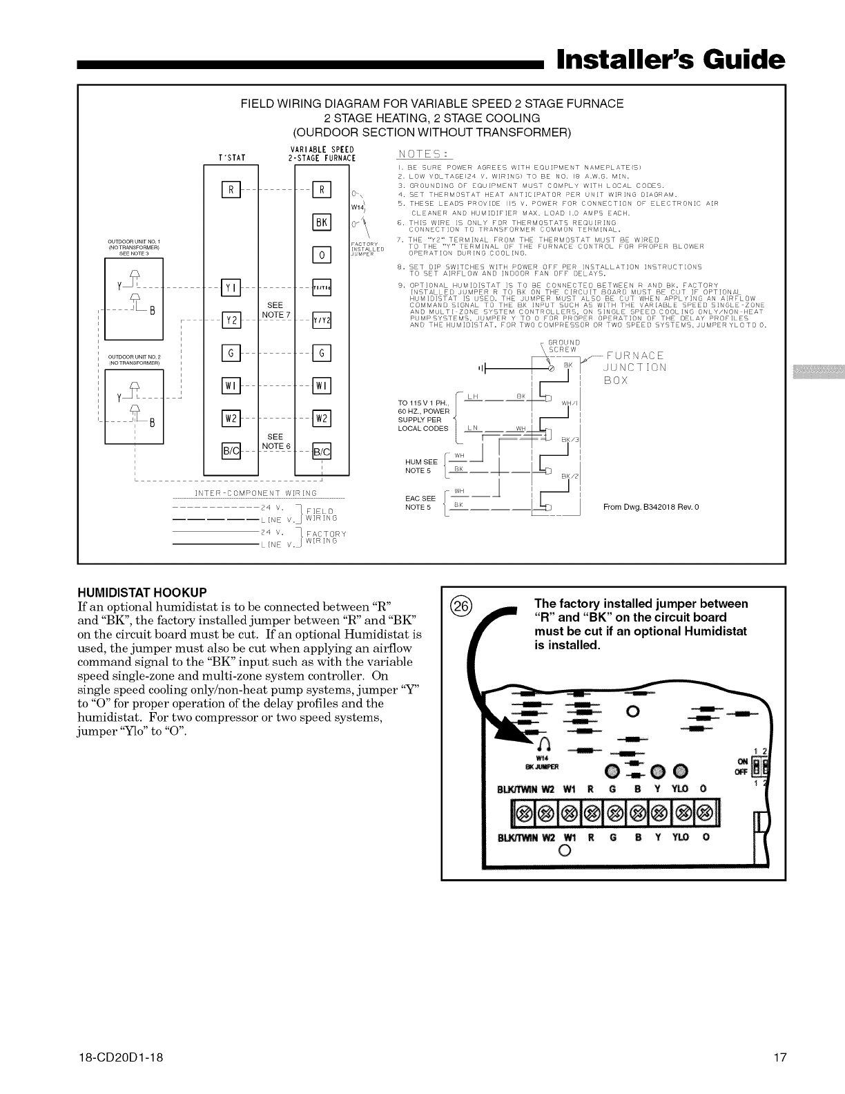
FIELD WIRING DIAGRAM FOR VARIABLE SPEED 2 STAGE FURNACE
2 STAGE HEATING, 2 STAGE COOLING
(OURDOOR SECTION WITHOUT TRANSFORMER)
T'STAT
D
SEE
NOTE 7
SEE
NOTE6
EO
D
D
Eg
[]
VARIABLE SPEED
2-STAGE FURNACE
D O_\
@
D
B
D
D
D
B
D
i
FACTORY
INSTALLED
JUMPER
NOTES :
I. BE SURE POWER AGREES W[TH EQUIPMENT NAMEPLATE(S}
2. LOW VOLTAGE 24 Y. WIRING) TO BE NO. 18 A.W.G. M[ .
2. GROUNDING OF EQUIPMENT MUST COMPLY W[TH LOCAL CODES.
4. SET THERMOSTAT HEAT ANTICI/SATOR >E_ UNIT WIRING D[AGRAM.
5. THESE LEA}S PROVIDE 115 V. PDWER FOR CONNECTION OF ELECTRONIC A[R
CLEANER AND HUM[D]FIER MAX. LOAD 1.0 AMPS EACH.
B. THIS WIRE IS ONLY FOR THERMOSTATS REQUIR[ O
CONNECT]ON TO TRANSFORMER COMMON TERMINAL.
7. THE *'Y2" TERM]NAL FROM THE THERMOSTAT MLGT BE WIRE[I)
TO THE "Y" TERMINAL OF THE FURNACE CONTROL FOR PROPER BLOWER
OPERAT]ON DURING COOLING.
8. SET DIP SWITCHES WITH POWER OFF PER INSTALLAT]ON INSTRUCT]ONS
TG ET AIRFLOW AN[) INDOOR FAN OFF }ELAYS.
9. OPTIONAL HUM[D[STAT ]S TO BE CONNECTED BETWEEN R AND BK. FACTORY
IN TALLED J JMPER R TO BK ON THE CIRCUIT BOARD M/ T BE CLT ]F OPTIONAL
HUMIDISTAT [G SED. THE JUMPER MUST ALGO BE CUT WHEN APPLY] G AN AIRFLOW
COMMAND SIGNAL TO THE BK INPUT SUCH AS WITH THE VARIABLE SPEED S]NOLE ZONE
AND MULTI ZONE SYSTEM CONTROLLERS, ON SINGLE SPEED COOLING ONLY/NON HEAT
PUMPSYSTEMS, JUMPER Y TO 0 FOR PROPER OPERAT]ON OF THE DELAY PROFILES
AN[} THE H M1}1 TAT. FOR TWG COMPRESSOR OR TWO SPEED SYSTEMS, JUMPER YLO TO O.
INTER COMPONENT WIRING
24 V. _ FIELD
LINE V.• WIRING
24 V. _ FACTORY
LINE V.• WIRING
HUMIDISTAT HOOKUP
If an optional humidistat is to be connected between "R"
and "BK", the factory installed jumper between "R" and "BK"
on the circuit board must be cut. If an optional Humidistat is
used, the jumper must also be cut when applying an airflow
command signal to the "BK" input such as with the variable
speed single-zone and multi-zone system controller. On
single speed cooling only/non-heat pump systems, jumper "Y"
to "O" for proper operation of the delay profiles and the
humidistat. For two compressor or two speed systems,
jumper "Ylo" to "0".
The factory installed jumper between
"R" and "BK" on the circuit board
must be cut if an optional Humidistat
is installed.
18-CD20D1-18 17

Installer's Guide
FIRE OR EXPLOSION HAZARD
Failure to follow the safety warnings exactly could result in
serious injury, death or property damage.
Never test for gas leaks with an open flame. Use a com-
mercially available soap solution made specifically for the
detection of leaks to check all connections. A fire or
explosion may result causing property damage, personal
injury, or loss of life.
(_ LEFT SIDE PIPING (STANDARD)
MANUAL MAIN
SHUTOFF
UNION JOINT
DRIP LEG
AUTOMATIC GAS VALVE
WITH MANUAL SHUTOFF
RIGHT SIDE PIPING (OPTIONAL)
SHUTOFF VALVE
UNION JOINT
DRIP LEG
WITH MANUAL SHUTOFF
TOP VIEW OF RIGHT SIDE PIPING
J
TO PREVENT AN EXPLOSION OR POSSIBLE INJURY,
DEATH AND EQUIPMENT DAMAGE, DO NOT STORE
COMBUSTIBLE MATERIALS, GASOLINE OR OTHER
FLAMMABLE VAPORS OR LIQUIDS NEAR THE UNIT.
GAS PIPING
This unit is shipped standard for left side installation of gas
piping. A piping knockout is also provided in the right side
for an alternate piping arrangement. The installation of
piping shall be in accordance with piping codes and the
regulations of the local gas company. Pipe joint compound
must be resistant to the chemical reaction with liquefied
petroleum gases.
Refer to piping Table 8 for delivery sizes. Connect gas supply
to the unit, using a ground joint union and a manual shut-off
valve as shown in Figure 27. National codes require a
condensation drip leg to be installed ahead of the controls as
shown in Figure 27.
The furnace and its individual shut-off valve must be discon-
nected from the gas supply piping system during any pres-
sure testing of that system at test pressures in excess of
1/2 psig.
The furnace must be isolated from the gas supply piping by
closing its individual manual shut-off valve during any
pressure testing of the gas supply piping system at test
pressures equal to or less than 1/2 psig.
Use a backup wrench on the gas valve when installing gas
piping to prevent damage to the gas valve and manifold
assembly.
NOTE:
Maximum pressure to the gas valve for natural gas is
13.8" W.C. Minimum pressure is 5.0" W.C. Maximum
pressure to the gas valve for propane is 13.8" W.C.
Minimum pressure is 11.0" W.C.
All gas fittings must be checked for leaks using a soapy
solution before lighting the furnace. DO NOT CHECK WITH
AN OPEN FLAME!
The following warning complies with State of California law, Proposition 65.
Hazardous Gases!
Exposure to fuel substances or by-products of incomplete
fuel combustion is believed by the state of California to
cause cancer, birth defects, or other reproductive harm.
COMBUSTION AND INPUT CHECK
1. Make sure all gas appliances are off except the furnace.
2. Clock the gas meter with the furnace operating (deter-
mine the dial rating of the meter) for one revolution.
3. Match the "See" column in the gas flow (in cfh) Table 13
with the time clocked.
4. Read the "Flow" column opposite the number of seconds
clocked.
5. Use the following factors if necessary:
For 1 Cu. Ft. Dial Gas Flow CFH =
Chart Flow Reading + 2
For 1/2 Cu Ft. Dial Gas Flow CFH =
Chart Flow Reading + 4
For 5 Cu. Ft. Dial Gas Flow CFH =
10X Chart Flow Reading + 4
6. Multiply the final figure by the heating value of the gas
obtained from the utility company and compare to the
nameplate rating. This must not exceed the nameplate
rating.
18 18-CD20D 1-18
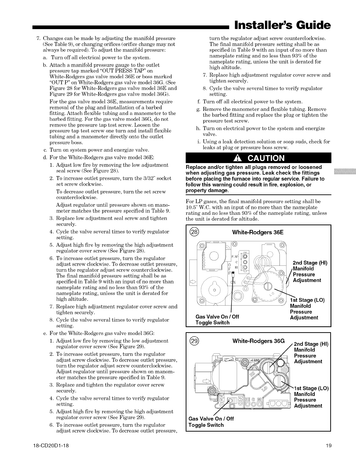
7. Changes can be made by adjusting the manifold pressure
(See Table 9), or changing orifices (orifice change may not
always be required). To adjust the manifold pressure:
a. Turn off all electrical power to the system.
b. Attach a manifold pressure gauge to the outlet
pressure tap marked "OUT PRESS TAP" on
White-Rodgers gas valve model 36E or boss marked
"OUT P" on White-Rodgers gas valve model 36G. (See
Figure 28 for White-Rodgers gas valve model 36E and
Figure 29 for White-Rodgers gas valve model 36G).
For the gas valve model 36E, measurements require
removal of the plug and installation of a barbed
fitting. Attach flexible tubing and a manometer to the
barbed fitting. For the gas valve model 36G, do not
remove the pressure tap test screw. Loosen the
pressure tap test screw one turn and install flexible
tubing and a manometer directly onto the outlet
pressure boss.
c. Turn on system power and energize valve.
d. For the White-Rodgers gas valve model 36E:
1. Adjust low fire by removing the low adjustment
seal screw (See Figure 28).
2. To increase outlet pressure, turn the 3/32" socket
set screw clockwise.
To decrease outlet pressure, turn the set screw
counterclockwise.
Adjust regulator until pressure shown on mano-
meter matches the pressure specified in Table 9.
3. Replace low adjustment seal screw and tighten
securely.
4. Cycle the valve several times to verify regulator
setting.
5. Adjust high fire by removing the high adjustment
regulator cover screw (See Figure 28).
6. To increase outlet pressure, turn the regulator
adjust screw clockwise. To decrease outlet pressure,
turn the regulator adjust screw counterclockwise.
The final manifold pressure setting shall be as
specified in Table 9 with an input of no more than
nameplate rating and no less than 93% of the
nameplate rating, unless the unit is derated for
high altitude.
7. Replace high adjustment regulator cover screw and
tighten securely.
8. Cycle the valve several times to verify regulator
setting.
e. For the White-Rodgers gas valve model 36G:
1. Adjust low fire by removing the low adjustment
regulator cover screw (See Figure 29).
2. To increase outlet pressure, turn the regulator
adjust screw clockwise. To decrease outlet pressure,
turn the regulator adjust screw counterclockwise.
Adjust regulator until pressure shown on manom-
eter matches the pressure specified in Table 9.
3. Replace and tighten the regulator cover screw
securely.
4. Cycle the valve several times to verify regulator
setting.
5. Adjust high fire by removing the high adjustment
regulator cover screw (See Figure 29).
6. To increase outlet pressure, turn the regulator
adjust screw clockwise. To decrease outlet pressure,
Installer's Guide
turn the regulator adjust screw counterclockwise.
The final manifold pressure setting shall be as
specified in Table 9 with an input of no more than
nameplate rating and no less than 93% of the
nameplate rating, unless the unit is derated for
high altitude.
7. Replace high adjustment regulator cover screw and
tighten securely.
8. Cycle the valve several times to verify regulator
setting.
f. Turn off all electrical power to the system.
g. Remove the manometer and flexible tubing. Remove
the barbed fitting and replace the plug or tighten the
pressure test screw.
h. Turn on electrical power to the system and energize
valve.
i. Using a leak detection solution or soap suds, check for
leaks at plug or pressure boss screw.
Replace and/or tighten all plugs removed or loosened
when adjusting gas pressure. Leak check the fittings
before placing the furnace into regular service. Failure to
follow this warning could result in fire, explosion, or
property damage.
For LP gases, the final manifold pressure setting shall be
10.5" W.C. with an input of no more than the nameplate
rating and no less than 93% of the nameplate rating, unless
the unit is derated for altitude.
@White-Rodgers 36E
2nd Stage (HI)
Pressure
Adjustment
@
Gas Valve On /Off
Toggle Switch
1st Stage (LO)
Manifold
Pressure
Adjustment
White-Rodgers 36G 2nd Stage (HI)
Manifold
Pressure
Adjustment
Gas Valve On /Off
Toggle Switch
Manifold
Pressure
Adjustment
18-CD20D1-18 19
Installer's Guide
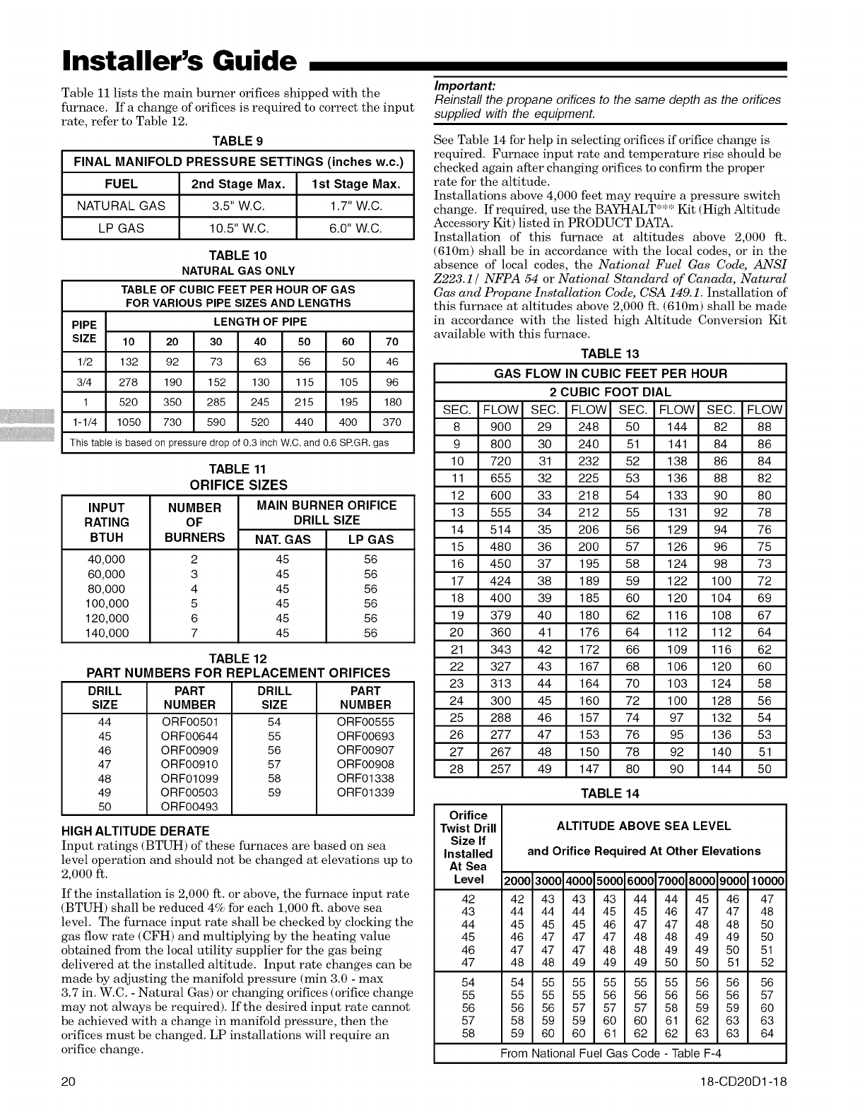
Table 11 lists the main burner orifices shipped with the
furnace. If a change of orifices is required to correct the input
rate, refer to Table 12.
TABLE 9
FINAL MANIFOLD PRESSURE SETTINGS (inches w.c.)
FUEL 2nd Stage Max. 1st Stage Max.
NATURAL GAS 3.5" W.C. 1.7" W.C.
LP GAS 10.5" W.C. 6.0" W.C.
TABLE 10
NATURALGAS ONLY
TABLE OF CUBIC FEET PER HOUR OF GAS
FOR VARIOUSPIPE SIZES AND LENGTHS
PIPE LENGTH OF PIPE
SIZE 10 20 30 40 50 60 70
1/2 132 92 73 63 56 50 46
3/4 278 190 152 130 115 105 96
1 520 350 285 245 215 195 180
1-1/4 1050 730 590 520 440 400 370
This table is based on pressure drop of 0.3 inch W.C. and 0.6 SRGR. gas
INPUT
RATING
BTUH
40,000
60,000
80,000
100,000
120,000
140,000
TABLE 11
ORIFICE SIZES
MAIN BURNER ORIFICE
DRILL SIZE
NUMBER
OF
BURNERS
2
3
4
5
6
7
NAT. GAS
45
45
45
45
45
45
LP GAS
56
56
56
56
56
56
TABLE 12
PART NUMBERS FOR REPLACEMENT ORIFICES
DRILL
SIZE
44
45
46
47
48
49
50
PART
NUMBER
ORF00501
ORF00644
ORF00909
ORF00910
ORF01099
ORF00503
ORF00493
DRILL
SIZE
54
55
56
57
58
59
PART
NUMBER
ORF00555
ORF00693
ORF00907
ORF00908
ORF01338
ORF01339
HIGH ALTITUDE DERATE
Input ratings (BTUH) of these furnaces are based on sea
level operation and should not be changed at elevations up to
2,000 ft.
If the installation is 2,000 ft. or above, the furnace input rate
(BTUH) shall be reduced 4% for each 1,000 ft. above sea
level. The furnace input rate shall be checked by clocking the
gas flow rate (CFH) and multiplying by the heating value
obtained from the local utility supplier for the gas being
delivered at the installed altitude. Input rate changes can be
made by adjusting the manifold pressure (min 3.0 - max
3.7 in. W.C. -Natural Gas) or changing orifices (orifice change
may not always be required). If the desired input rate cannot
be achieved with a change in manifold pressure, then the
orifices must be changed. LP installations will require an
orifice change.
Important:
Reinstall the propane orifices to the same depth as the orifices
supplied with the equipment.
See Table 14 for help in selecting orifices if orifice change is
required. Furnace input rate and temperature rise should be
checked again after changing orifices to confirm the proper
rate for the altitude.
Installations above 4,000 feet may require a pressure switch
change. If required, use the BAYHALT*** Kit (High Altitude
Accessory Kit) listed in PRODUCT DATA.
Installation of this furnace at altitudes above 2,000 ft.
(610m) shall be in accordance with the local codes, or in the
absence of local codes, the National Fuel Gas Code, ANSI
Z223.1 / NFPA 54 or National Standard of' Canada, Natural
Gas and Propane Installation Code, CSA 149.1. Installation of
this furnace at altitudes above 2,000 ft. (610m) shall be made
in accordance with the listed high Altitude Conversion Kit
available with this furnace.
TABLE 13
GAS FLOW IN CUBIC FEET PER HOUR
2 CUBIC FOOT DIAL
SEC. FLOW SEC. FLOW SEC. FLOW SEC. FLOW
8 900 29 248 50 144 82 88
9 800 30 240 51 141 84 86
10 720 31 232 52 138 86 84
11 655 32 225 53 136 88 82
12 600 33 218 54 133 90 80
13 555 34 212 55 131 92 78
14 514 35 206 56 129 94 76
15 480 36 200 57 126 96 75
16 450 37 195 58 124 98 73
17 424 38 189 59 122 100 72
18 400 39 185 60 120 104 69
19 379 40 180 62 116 108 67
20 360 41 176 64 112 112 64
21 343 42 172 66 109 116 62
22 327 43 167 68 106 120 60
23 313 44 164 70 103 124 58
24 300 45 160 72 100 128 56
25 288 46 157 74 97 132 54
26 277 47 153 76 95 136 53
27 267 48 150 78 92 140 51
28 257 49 147 80 90 144 50
TABLE 14
Orifice
Twist Drill
Size If
Installed
At Sea
Level
42
43
44
45
46
47
ALTITUDE ABOVE SEA LEVEL
and Orifice Required At Other Elevations
2000 3000 4000 5000 6000 7000 8000 9000 10000
42 43 43 43 44 44 45 46 47
44 44 44 45 45 46 47 47 48
45 45 45 46 47 47 48 48 50
46 47 47 47 48 48 49 49 50
47 47 47 48 48 49 49 50 51
48 48 49 49 49 50 50 51 52
54 54 55 55 55 55 55 56 56 56
55 55 55 55 56 56 56 56 56 57
56 56 56 57 57 57 58 59 59 60
57 58 59 59 60 60 61 62 63 63
58 59 60 60 61 62 62 63 63 64
From National Fuel Gas Code-Table F-4
18-CD20D1-1820
DO NOT attempt to manually light the burner. Failure to
follow this warning could result in property damage, per-
sonal injury or death.
START UP AND ADJUSTMENT
PRELIMINARY INSPECTIONS
With gas and electrical power "OFF"
1. Duct connections are properly sealed
2. Filters are in place
3. Venting is properly assembled
4. Blower door is in place
Turn knot) on main gas valve within the unit to the "OFF"
position. Turn the external gas valve to "ON". Purge the air
from the gas lines. After purging, check all gas connections
for leaks with a soapy solution -- DO NOT CHECK WITH
AN OPEN FLAME. Allow 5 minutes for any gas that might
have escaped to dissipate. LP Gas, being heavier than air,
may require forced ventilation. Turn the knob on the gas
valve in the unit to the "ON" position.
LIGHTING INSTRUCTIONS
Lighting instructions appear on each unit. Each
installation must be checked out at the time of
initial start up to insure proper operation of all
components. Check out should include putting
the unit through one complete cycle as outlined
below.
Turn on the main electrical supply and set the thermostat
above the indicated temperature. The ignitor will automati-
cally heat, then the gas valve is energized to permit the flow
of gas to the burners. After ignition and flame is established,
the flame control module monitors the flame and supplies
power to the gas valve until the thermostat is satisfied.
TO SHUT OFF
For complete shutdown: Move the control switch on the main
gas valve to the "OFF" position (See Figures 28 and 29).
Disconnect the electrical supply to the unit.
If this is done during the cold weather months, provisions
must be taken to prevent freeze-up of all water pipes and
water receptacles. Failure to follow this warning could
result in property damage.
Whenever your house is to be vacant, arrange to have
someone inspect your house for proper temperature. This
is very important in below freezing weather. If for any
reason your furnace should fail to operate damage could
result, such as frozen water pipes.
FIRE OR EXPLOSION HAZARD
Failure to follow the safety warnings exactly could result in
serious injury, death or property damage.
Never test for gas leaks with an open flame. Use a com-
mercially available soap solution made specifically for the
detection of leaks to check all connections. A fire or
explosion may result causing property damage, personal
injury, or loss of life.
Installer's Guide
SEQUENCE OF OPERATION
Thermostat call for heat (2-stage thermostat)
Call for 1st stage only:
R and W1 thermostat contacts close signaling the control
module to run its self-check routine. After the control module
has verified that the 1st stage pressure switch contacts are
open and the limit switch(es) contacts are closed, the draft
blower will be energized.
As the induced draft blower comes up to speed, the pressure
switch contacts will close and the ignitor warm up period will
begin. The ignitor will heat for approx. 20 seconds, then the
gas valve is energized in 1st stage to permit gas flow to the
burners. The flame sensor confirms that ignition has been
achieved within the 4 second ignition trial period.
As the flame sensor confirms that ignition has been achieved,
the delay to fan ON period begins timing and after approx.
45 seconds the indoor blower motor will be energized at low
speed and will continue to run during the heating cycle.
Call for 2nd stage after 1st stage:
R and W2 thermostat contacts close signaling a call for 2nd
stage heat. After a 30 second delay, the induced draft blower
will be energized on high speed and the 2nd stage pressure
switch contacts will close allowing the gas valve to be energized
in 2nd stage and the indoor [)lower motor in high speed.
2nd stage satisfied, 1st stage still called:
n andW2thermostatcontactsopensignalingthat 2ndstage
heating requirements are satisfied. The induced draft [)lower
is reduced to low speed allowing the 2nd stage pressure
switch contacts to open and the gas valve is reduced to 1st
stage. After approx. 30 seconds the indoor blower motor is
reduced to low speed.
1st stage satisfied:
R and W1 thermostat contacts open signaling that 1st stage
heating requirements are satisfied. The gas valve will close
and the induced draft blower will be de-energized. The indoor
blower motor will continue to run for the fan off period (Field
selectable at 60, 100, 140 or 180 seconds - Factory setting is
100 seconds), then will be de-energized by the control module.
Thermostat call for heat (1-stage Thermostat)
R and W1/W2 (jumpered) thermostat contacts close signaling
a call for heat. 1st stage sequence of operation remains the
same as above. 2nd stage heat has a 10 minute delay from
the time of 1st stage ignition.
Thermostat satisfied:
R and W1/W2 (jumpered) contacts open signaling the control
module to close the gas valve and de-energize the induced
draft blower. The indoor blower motor will continue to
operate at high heat speed for approx. 30 seconds after the
flames are extinguished and then is switched to low heat
speed for the remaining FAN-OFF period.
INDOOR BLOWER OPERATION WITH THERMOSTAT FAN
SWITCH "ON":
Fan is R-G.
R-W energized, fan continues to run without interruption.
Heat Low speed if it is a two stage furnace.
Heat speed if it is a single stage furnace.
18-CD20D1-18 21
Installer's Guide
EXPLOSION HAZARD!
PROPANE GAS IS HEAVIER THAN AIR AND MAY COL-
LECT IN ANY LOW AREAS OR CONFINED SPACES. IN
ADDITION, ODORANT FADE MAY MAKE THE GAS
UNDETECTABLE EXCEPT WITH A WARNING DEVICE. IF
THE GAS FURNACE IS INSTALLED IN A BASEMENT, AN
EXCAVATED AREA OR A CONFINED SPACE, IT IS
STRONGLY RECOMMENDED TO CONTACT A GAS
SUPPLIER TO INSTALL A GAS DETECTING WARNING
DEVICE IN CASE OF A GAS LEAK.
NOTE: The manufacturer of your furnace does NOT test any
detectors and makes no representations regarding any
brand or type of detector.
CONTROL AND SAFETY SWITCH
ADJUSTMENT
LIMIT SWITCH CHECK OUT
The limit switch is a safety device designed to close the gas
valve should the furnace become overheated. Since proper
operation of this switch is important to the safety of the unit,
it must be checked out on initial start up by the
installer.
To check for proper operation of the limit switches, set the
thermostat to a temperature higher than the indicated
temperature to bring on the gas valve. Restrict the airflow
by blocldng the return air or by disconnecting the blower.
When the furnace reaches the maximum outlet temperature
as shown on the rating plate, the burners must shut off. If
they do not shut off after a reasonable time and overheating
is evident, a faulty limit switch is probable and the limit
switch must be replaced. After checking the operation of the
................................................................................limit control, be sure to remove the paper or cardboard from
the return air inlet, or reconnect the blower.
This setting is equivalent to BAY24X045 relay
benefit.
This selection provides ENHANCED MODE, which
is a ramping up and ramping down of the blower
speed to provide improved comfort, quietness,
and potential energy savings. See Wiring Diagram
notes on the unit or in the Service Facts for
complete wiring setup for ENHANCED MODE. The
graph which follows, shows the ramping process.
OFF
50%
80%
100% if necessary
50%
_ast Cooling Efficiency
I,I I I 3I
minute minutes minutes
OFF
See Wiring Diagram on the unit or in the Service Facts
for complete wiring setup for Enhanced Mode.
INDOOR BLOWER TIMING
Heating: The Integrated Furnace Control (IFC) controls the
variable speed indoor blower. The blower "on" time is fixed at
45 seconds after ignition. The FAN-OFF period is field
selectable by dip switches #1 and #2 located on the Inte-
grated Furnace Control between the 5-pin and 9-pin wire
connectors. The delay may be set at 60, 100, 140, or 180 sec-
onds. The factory setting is 100 seconds (See unit wiring
diagram).
Cooling: The fan delay-off period is set by dip switches on the
Integrated Furnace Control. The options for cooling delay off
is field selectable by dip switches #5 and #6.
The following table and graph explain the delay-off settings:
COOLING OFF - DELAY OPTIONS
NOMINAL
SWITCH SETTINGS SELECTION AIRFLOW
5 - OFF 6 - OFF NONE SAME
5 - ON 6 - OFF 1.5 MINUTES 100% *
5 - OFF 6 - ON 3 MINUTES 50%
5 - ON 6 - ON ** 50 - 100%
Disconnect power to the unit before removing the blower
door. Failure to follow this warning could result in property
damage, personal injury or death.
This unit is equipped with a blower door switch which cuts
power to the blower and gas valve causing shutdown when
the door is removed. Operation with the door removed or
ajar can permit the escape of dangerous fumes. All panels
must be securely closed at all times for safe operation of
the furnace.
NOTE:
Direct drive motors have bearings which are permanently
lubricated and under normal use, lubrication is not
recommended.
ROOM AIR THERMOSTAT
HEAT ANTICIPATOR ADJUSTMENT
Set the thermostat heat anticipator according to the current
flow measured, or the settings found in the notes on the
furnace wiring diagram (found inside the furnace casing).
INSTRUCTIONS TO THE OWNERS
In the event that electrical, fuel, or mechanical fail-
ures occur, the owner should immediately turn the gas
supply off at the manual gas valve, located in the
burner compartment (See Figure 27).
Also turn off electrical power to the furnace and
contact the service agency designated by your dealer.
Should overheating occur, or the gas supply fail to shut off,
shut off the gas valve to the unit before shutting off the
electrical supply. Failure to follow this warning could result
in property damage, personal injury, or death.
22 18-CD20D1-18

ABNORMAL CONDITIONS
1. EXCESSIVE COMBUSTION PRESSURE (WIND IN
EXCESS OF 40 MP.H.) VENT OR FLUE BLOCKAGE
If pressure against induced draft blower outlet becomes
excessive, the pressure switch will open and shut off the
gas valve until acceptable combustion pressure is again
available.
2. LOSS OF FLAME
If loss of flame occurs during a heating cycle, or flame is
not present at the sensor, the flame control module will
close the gas valve. The flame control module will then
recycle the ignition sequence, then if ignition is not
achieved, it will shut off the gas valve and lock out the
system.
3. POWER FAILURE
If there is a power failure during a heating cycle, the
system will restart the ignition sequence automatically
when power is restored, if the thermostat still calls for heat.
4. GAS SUPPLY FAILURE
If loss of flame occurs during a heating cycle, the system
integrated control module will recycle the ignition
sequence, then if ignition is not achieved, the integrated
control module will shut off the gas valve and lock out
the system.
5. INDUCED DRAFT BLOWER FAILURE
If pressure is not sensed by the pressure switch, the
contacts will remain open and not allow the gas valve to
open, therefore the unit will not start. If failure occurs
during a running cycle, the pressure switch contacts will
open and the gas valve will close to shut the unit down.
6. RESET AFTER LOCKOUT
When the integrated control module has shut the system
down and gone into lockout, the system must be manu-
ally reset before the unit will restart. To reset, turn the
system power off, then on, then off and then on again
within 30 seconds. This may be done at the unit's power
source or at the thermostat. The system will not reset
unless the procedure of[:on-of[:on is completed within
30 seconds.
Carbon monoxide, fire or smoke can cause serious bodily
injury, death, and!or property damage.
A variety of potential sources of carbon monoxide can be
found in a building or dwelling such as gas-fired clothes
dryers, gas cooking stoves, water heaters, furnaces and
fireplaces. The U.S. Consumer Product Safety Commission
recommends that users of gas-burning appliances install
carbon monoxide detectors as well as fire and smoke detec-
tors per the manufacturers installation instructions to help
alert dwelling occupants of the presence of fire, smoke or
unsafe levels of carbon monoxide. These devices should be
listed by Underwriters Laboratories, Inc. Standards ['or
Single and Multiple Station Carbon Monoxide Alarms,
UL 2034 or CSA International Standard, Residential
Carbon Monoxide Alarming Devices, CSA 6.19
NOTE:
The manufacturer of your furnace does not test any detec-
tors and makes no representations regarding any brand or
type of detector.
Installer's Guide
The following warning complies with State of California law, Proposition 65.
This product contains fiberglass wool insulation!
Fiberglass dust and ceramic fibers are believed by the
State of California to cause cancer through inhalation.
Glasswool fibers may also cause respiratory, skin, or
eye irritation.
PRECAUTIONARY MEASURES
•Avoid breathing fiberglass dust.
• Use a NIOSH approved dust/mist respirator.
• Avoid contact with the skin or eyes. Wear long-sleeved,
loose-fitting clothing, gloves, and eye protection.
• Wash clothes separately from other clothing: rinse
washer thoroughly.
• Operations such as sawing, blowing, tear-out, and
spraying may generate fiber concentrations requiring
additional respiratory protection. Use the appropriate
NIOSH approved respirator in these situations.
FIRST AID MEASURES
Eye Contact - Flush eyes with water to remove dust.
If symptoms persist, seek medical
attention.
Skin Contact - Wash affected areas gently with soap
and warm water after handling.
Failure to follow safety warnings exactly, could result
in a fire or explosion causing property damage,
personal injury or loss of life.
-- Do not store or use gasoline or other flammable
vapors and liquids in the vicinity of this or any
other appliance.
-- WHAT TO DO IF YOU SMELL GAS
•Do not try to light any appliance.
•Do not touch any electrical switch;
do not use any phone in your building.
•Immediately call your gas supplier from a
neighbor's phone. Follow the gas supplier's
instructions.
•If you cannot reach your gas supplier,
call the fire department.
Installation and service must be performed by
a qualified installer, service agency or the gas
supplier.
iiiliii_iiiiiiii!!i!!i!!i!!i!!i!!i!!i!!i!!i!!i!!!iii
18-CD20D1-18 23
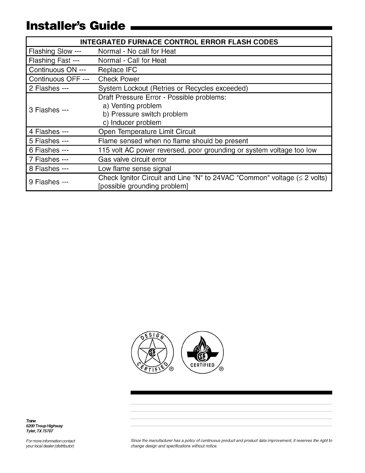
Installer's Guide
Flashing Slow---
Flashing Fast ---
Continuous ON ---
Continuous OFF ---
2 Flashes---
3 Flashes ---
4 Flashes ---
5 Flashes ---
6 Flashes ---
7 Flashes ---
8 Flashes ---
9 Flashes ---
INTEGRATED FURNACE CONTROL ERROR FLASH CODES
Normal - No call for Heat
Normal - Call for Heat
Replace IFC
Check Power
System Lockout (Retries or Recycles exceeded)
Draft Pressure Error - Possible problems:
a) Venting problem
b) Pressure switch problem
c) Inducer problem
Open Temperature Limit Circuit
Flame sensed when no flame should be present
115 volt AC power reversed, poor grounding or system voltage too low
Gas valve circuit error
Low flame sense signal
Check Ignitor Circuit and Line "N" to 24VAC "Common" voltage (_<2 volts)
[possible grounding problem]
Tl2Z_
6200 Troup Highway
Tyler, TX 75707
For more information contact Since the manufacturer has a policy of continuous product and product data improvement, it reserves the right to
your local dealer(distributor) change design and specifications without notice.
