TRANE Package Units(both Units Combined) Manual L0903217
User Manual: TRANE TRANE Package Units(both units combined) Manual TRANE Package Units(both units combined) Owner's Manual, TRANE Package Units(both units combined) installation guides
Open the PDF directly: View PDF ![]() .
.
Page Count: 4
i TALL
GUIDE
iMPORTANT -- This is customer property and is to remain with
this unit. Please return to service information
pack upon completion of work.
HDPC-IN-8A
18-AH06 D10-02
Library Service Literature
Product Section Unitary
Product Unitary Accessories
Model Heat Pressure Control
Literature Type Installer's Guide
Sequence 8A
Date September 1998
File No. SV-UN-ACC-HDPC-IN-8A 6/97
Supersedes HDPC-IN-8
Models-.
BAYLOAM323A
(208/230V/460V)
Used With:
TCC - F YCC - F WCC - F
TCX - F YCX- F WCX - F
TCY - F YCY- F WCY - F Head Pressure Control
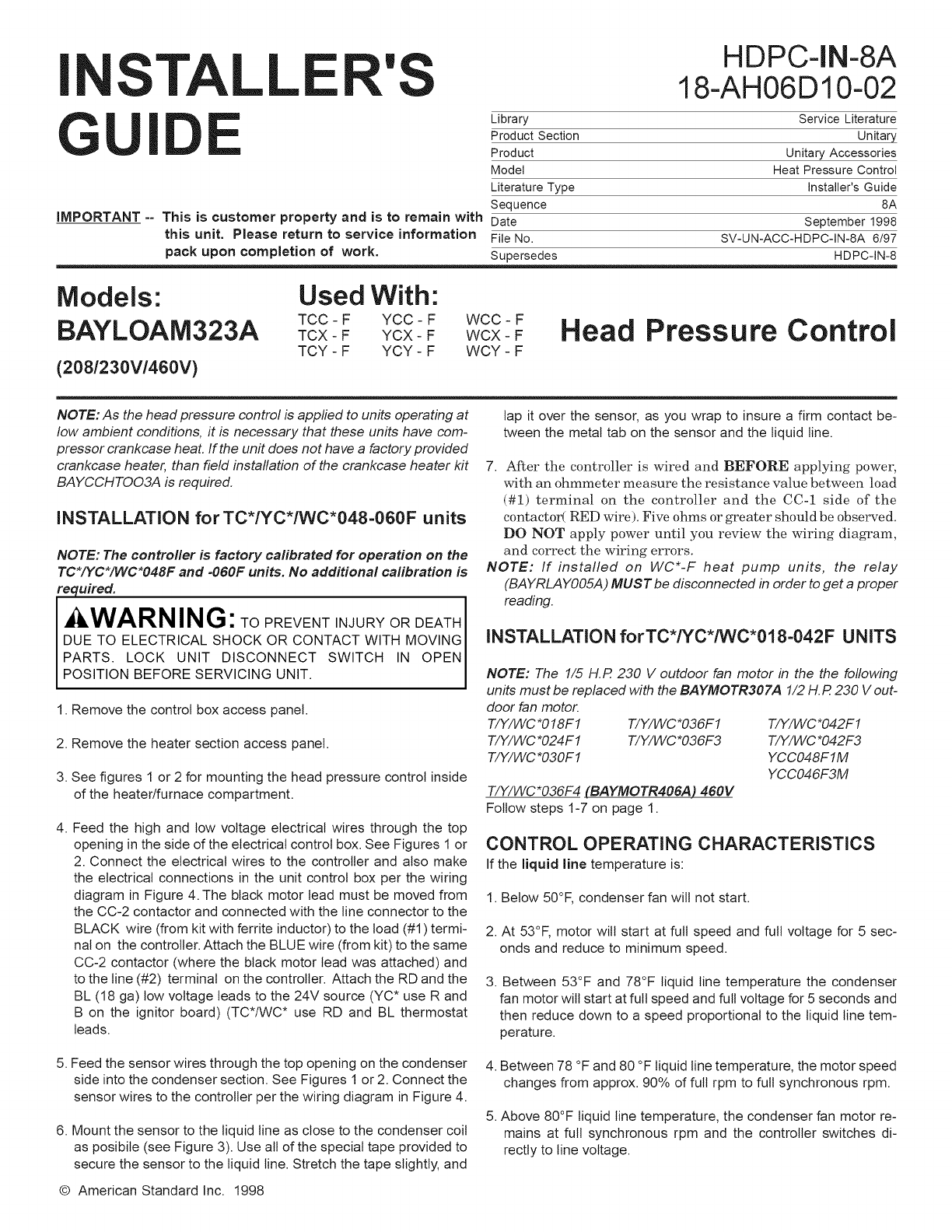
NOTE: As the head pressure control is applied to units operating at
low ambient conditions, it is necessary that these units have com-
pressor crankcase heat. If the unit does not have a factory provided
crankcase heater, than field installation of the crankcase heater kit
BAYCCHTOO3A is required.
iNSTALLATiON forTC*/YC*/WC*048=060F units
NOTE: The controller is factory calibrated for operation on the
TC*/YC*/WC*O48F and =060F units. No additional calibration is
required.
I WARNING: TOPREVENTINJURYORDEATH
DUE TO ELECTRICAL SHOCK OR CONTACT WITH MOVING
PARTS. LOCK UNIT DISCONNECT SWITCH IN OPEN
POSITION BEFORE SERVICING UNIT.
1. Remove the control box access panel.
2. Remove the heater section access panel.
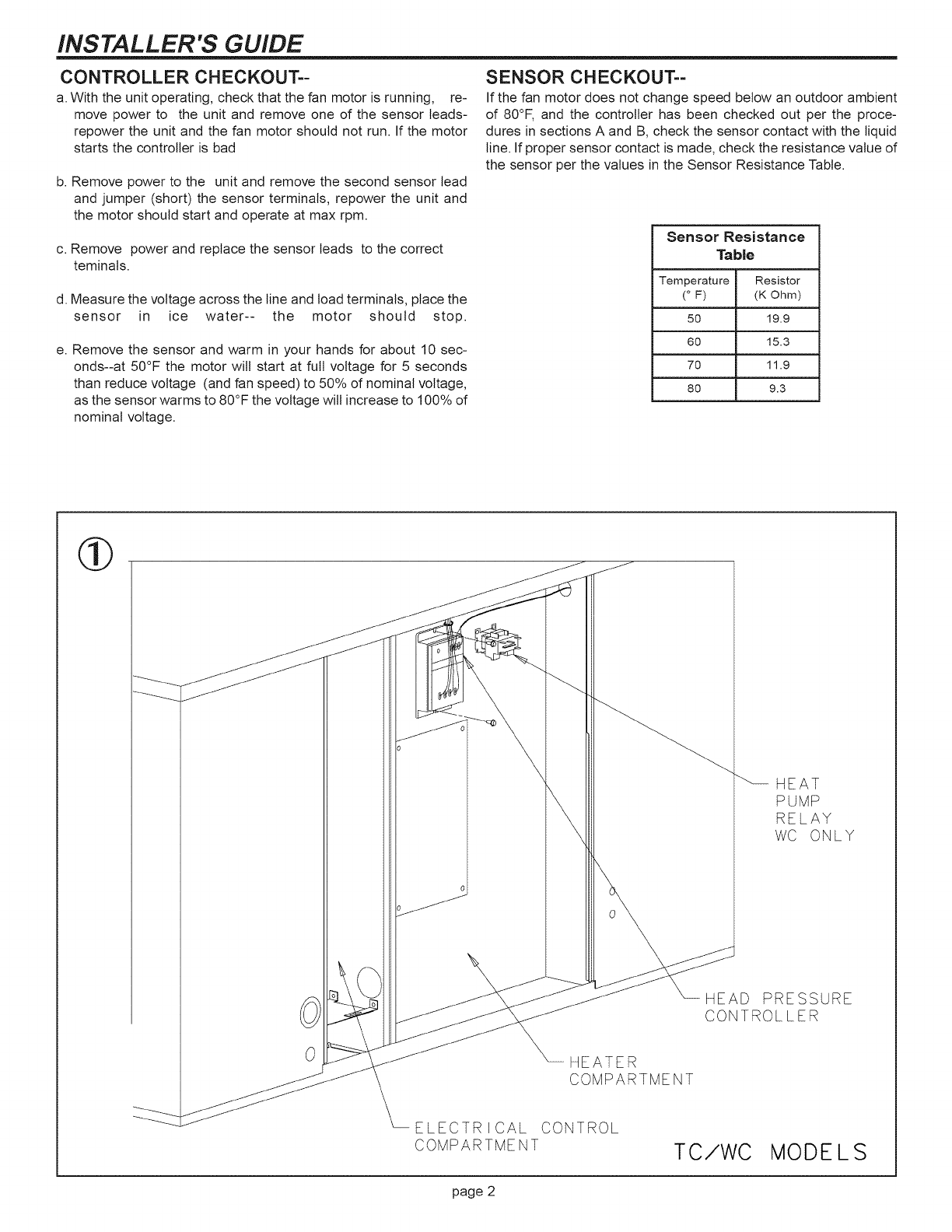
3. See figures 1 or 2 for mounting the head pressure control inside
of the heater/furnace compartment.
4. Feed the high and tow voltage electrical wires through the top
opening in the side of the electrical control box. See Figures 1 or
2. Connect the electrical wires to the controller and also make
the electrical connections in the unit control box per the wiring
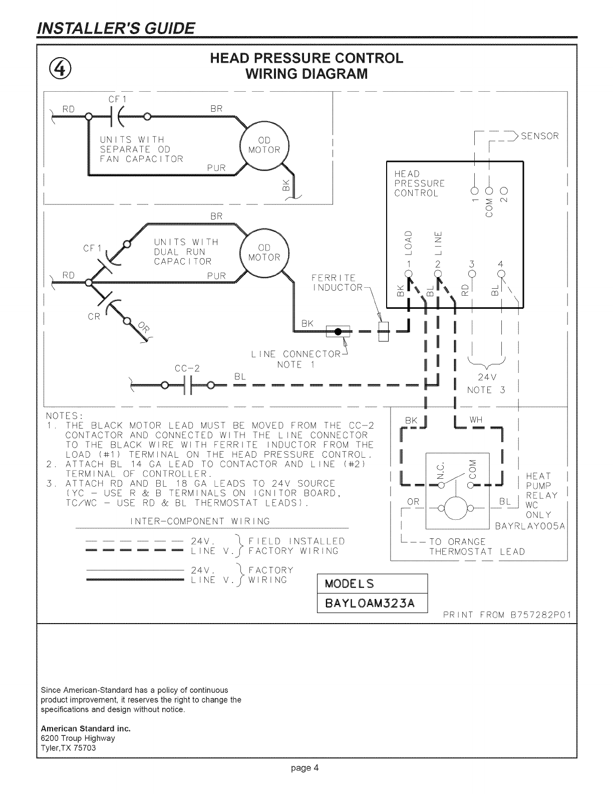
diagram in Figure 4. The black motor lead must be moved from
the CC-2 contactor and connected with the line connector to the
BLACK wire (from kit with ferrite inductor) to the load (#1) termi-
nal on the controller. Attach the BLUE wire (from kit) to the same
CC-2 contactor (where the black motor lead was attached) and
to the line (#2) terminal on the controller. Attach the RD and the
BL (18 ga) low voltage leads to the 24V source (YC* use R and
B on the ignitor board) (TC*/WC* use RD and BL thermostat
leads.
5. Feed the sensor wires through the top opening on the condenser
side into the condenser section. See Figures 1 or 2. Connect the
sensor wires to the controller per the wiring diagram in Figure 4.
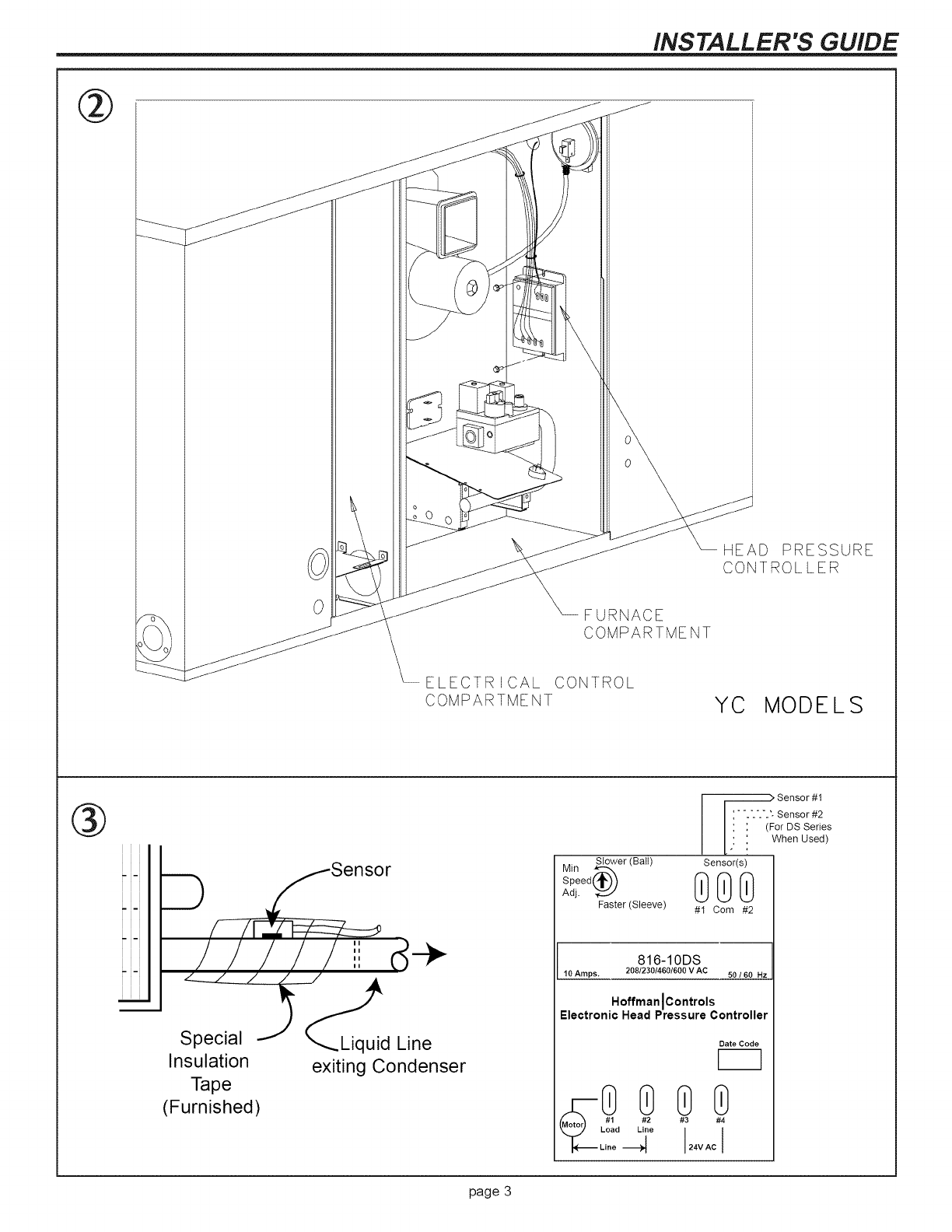
6. Mount the sensor to the liquid line as close to the condenser coil
as posibite (see Figure 3). Use all of the special tape provided to
secure the sensor to the liquid line. Stretch the tape slightly, and
© American Standard Inc. 1998
lap it over the sensor, as you wrap to insure a firm contact be-
tween the metal tab on the sensor and the liquid line.
7. After the controller is wired and BEFORE applying power,
with an ohmmeter measure the resistance value between load
(#1) terminal on the controller and the CC-1 side of the
contactor( RED wire). Five ohms or greater should be obselwed.
DO NOT apply power until you review the wiring diagram,
and correct the wiring errors.
NOTE: If installed on WC*-F heat pump units, the relay
(BAYRLAYOO5A) MUST be disconnected in order to get a proper
reading.
INSTALLATION forTC*/YC*/WC*018=042F UNITS
NOTE: The 1/5 H.R 230 V outdoor fan motor in the the following
units must be replaced with the BAYMOTR3OTA 1/2 H.R 230 V out-
door fan motor.
T/Y/WC *O18F1 T/Y/WC *O36F1
T/Y/WC *O24F1 T/Y/WC *O36F3
T/Y/WC *O3OF1
T/Y/WC*O36F4 (BAYMOTR406A) 460V
Follow steps 1-7 on page 1.
T/Y/WC*042F1
T/Y/WC *O42F3
YCCO48FIM
YCCO46F3M
CONTROL OPERATING CHARACTERISTICS
If the liquid line temperature is:
1. Below 50°F, condenser fan will not start.
2. At 53°F, motor will start at full speed and full voltage for 5 sec-
onds and reduce to minimum speed.
3, Between 53°F and 78°F liquid line temperature the condenser
fan motor will start at full speed and full voltage for 5 seconds and
then reduce down to a speed proportional to the liquid line tem-
perature.
4. Between 78 °F and 80 °F liquid line temperature, the motor speed
changes from approx. 90% of full rpm to full synchronous rpm.
5. Above 80°F liquid line temperature, the condenser fan motor re-
mains at full synchronous rpm and the controller switches di-
rectly to line voltage.
INSTALLER'S GUIDE
CONTROLLER CHECKOUT=-
a. With the unit operating, check that the fan motor is running, re-
move power to the unit and remove one of the sensor leads-
repower the unit and the fan motor should not run. If the motor
starts the controller is bad
b. Remove power to the unit and remove the second sensor lead
and jumper (short) the sensor terminals, repower the unit and
the motor should start and operate at max rpm.
c. Remove power and replace the sensor leads to the correct
teminals.
d. Measure the voltage across the line and load terminals, place the
sensor in ice water-- the motor should stop.
e. Remove the sensor and warm in your hands for about 10 sec-
onds--at 50°F the motor will start at full voltage for 5 seconds
than reduce voltage (and fan speed) to 50% of nominal voltage,
as the sensor warms to 80°F the voltage will increase to 100% of
nominal voltage.
SENSOR CHECKOUT==
If the fan motor does not change speed below an outdoor ambient
of 80°F, and the controller has been checked out per the proce-
dures in sections A and B, check the sensor contact with the liquid
line. If proper sensor contact is made, check the resistance value of
the sensor per the values in the Sensor Resistance Table.
Sensor Resistance
Table
Temperature Resistor
(° F) (K Ohm)
50 19.9
60 15.3
70 11.9
80 9.3
0HEATER
COMPARTMENT
HEAT
PUMP
RELAY
WC ONLY
HEAD PRESSURE
CONTROLLER
ELECTRbCAL CONTROL
COMPARTMENT TC/WC MODELS
page 2
INSTALLER'S GUIDE
@
0FURNACE
COMPARTMENT
HEAD PRESSURE
CONTROLLER
ELECTRECAL CONTROL
COMPARTMENT YC MODELS
®
....._---Sensor
///// d÷
€,
Special J _Liquid Line
Insulation exitingCondenser
Tape
(Furnished)
Min Slower (Ball)
Speed_"_
Adj. Faster (Sleeve)
__> Sensor #1
" ".'.'.'.'. Sensor #2
: (For DS Series
• When Used)
Sensor(s)
00O
#1 Com #2
816-10DS
10 Amps. 208123014601600 V AC 50 /60 Hz
Hoffman IControls
Electronic Head Pressure Controller
Date Code
#3 #4
24V AC I
page 3
INSTALLER'S GUIDE
®HEAD PRESSURE CONTROL
WiRiNG DIAGRAM
CF1
HEAD
PRESSURE
CONTROL
BR
CF1 3 3
PUR/_\ FERRITE
_ j INDUCTOR__ _ /_
• I ' |
CR oJ IIII i
L,NECONNECTOR_ I III I
CC-2 NOTE1 mIll i
b
NOTES:
1 THE BLACK MOTOR LEAD MUST BE MOVED FROM THE CC-2
CONTACTOR AND CONNECTED WITH THE LINE CONNECTOR
TO THE BLACK WIRE WITH FERRITE INDUCTOR FROM THE
LOAD (@1) TERMINAL ON THE HEAD PRESSURE CONTROL.
2 ATTACH BL 14 GA LEAD TO CONTACTOR AND LINE (@2)
TERMINAL OF CONTROLLER.
5 ATTACH RD AND BL 18 GA LEADS TO 24V SOURCE
(YC - USE R & B TERMINALS ON IGNITOR BOARD,
TC/WC - USE RD & BL THERMOSTAT LEADS).
INTER-COMPONENT WIRING
24V. _ FIELD INSTALLED
LINE V.S FACTORY WIRING
24V. FACTORY
-- LINE V. WIRING MODELS
_ c_
0
Lp
BAYLOAM525A
54
\
m
b
24V
NOTE 5
m !
_SJ L wH
J
L_ o
F9R_
}SENSOR
=-I !
J HEAT
PUMP
B_ wcRELAY
ONLY
BAYRLAYOOSA
TO ORANGE
THERMOSTAT LEAD
PRINT FROM B757282P01
Since American-Standard has a policy of continuous
product improvement, it reserves the right to change the
specifications and design without notice.
American Standard inc.
6200 Troup Highway
Tyler,TX 75703
page 4
