TRANE Furnace/Heater, Gas Manual L0903221
User Manual: TRANE TRANE Furnace/Heater, Gas Manual TRANE Furnace/Heater, Gas Owner's Manual, TRANE Furnace/Heater, Gas installation guides
Open the PDF directly: View PDF ![]() .
.
Page Count: 28
ISTALL
GU E
ALL phases of this installation must comply with
NATIONAL, STATE AND LOCAL CODES
*UD-IN-2
18-CD19D7-1
Library Service Literature
Product Section Unitary
Product Furnace -- Gas
Model *UD
Literature Type Installer's Guide
Sequence 2
Date April 1995
File No. SV-UN-FURN-*UD-IN-2 4/95
Supersedes New
Model:
*UD040C924H
*UD040C930H
*UD060C924H
*UD060C936H
*UD080C924H
*UD080C936H
*UD080C948H
*UD100C936H
*UD100C945H
*UD100C948H
*UD100C960H
*UD100C961H
*UD120C954H
*UD120C960H
*UD140C960H
* -- The first letter may be "A" or "T"
Upflow !Horizontal
Gas-Fired Furnaces
"Fan Assisted
Combustion System"
IMPORTANT-- This Document iscu stomer property and is to remain with this unit.
Please return to service information pack upon completion of work.
@
Since the manufacturer has a policy of continuous
product improvement, it reserves the right to change
specifications and design without notice.
Pub. No. 18-CD19D7-1
© American Standard Inc. 1995
INSTALLER 'S GUIDE
CONTENTS PAGE
INSTALLATION
General Installation Instructions .................................................................................................................................... 2
Location & Clearances ..................................................................................................................................................... 2
Horizontal Installation ..................................................................................................................................................... 3
Air for Combustion and Ventilation ........................................................................................................................... 3&4
Duct Connections .............................................................................................................................................................. 5
Return Air -- Filters ................................................................................................................................................... 5&6
Venting-- General Information ................................................................................................................................. 6&7
Venting Into a Masonry Chimney ............................................................................................................................ 7
Single Appliance Venting (with Tables) .............................................................................................................. 8-11
Common Venting (with Tables) ......................................................................................................................... 12-19
Venting Examples .............................................................................................................................................. 20-22
Electrical Connections .................................................................................................................................................... 23
Gas Piping ....................................................................................................................................................................... 23
START-UP AND ADJUSTMENT
Preliminary Inspections ................................................................................................................................................. 24
Combustion and Input Check ........................................................................................................................................ 24
High Altitude Derate ...................................................................................................................................................... 24
Sequence of Operation ................................................................................................................................................... 25
Lighting Instructions ..................................................................................................................................................... 25
Control and Safety Switch Adjustment ......................................................................................................................... 26
ABNORMAL CONDITIONS .............................................................................................................................................. 26
FIELD WIRING DIAGRAMS ............................................................................................................................................ 27
OUTLINE DRAWING ......................................................................................................................................................... 28
GENERAL
The manufacturer assumes no responsibility for equipment
installed in violation of any code or regulation.
It is recommended that Manual J of the Air Conditioning
Contractors Association (ACCA) or A.R.I. 230 be followed in
estimating heating requirements. When estimating heating
requirements for installation at Altitudes above 2000 ft., re-
member the gas input must be reduced (See GAS INPUT
ADJUSTMENT).
Material in this shipment has been inspected at the
factory and released to the transportation agency with-
out known damage. Inspect exterior of carton for evi-
dence of rough handling in shipment. Unpack carefully
after moving equipment to approximate location. If dam-
age to contents is found, report the damage immediately
to the delivering agency.
Codes and local utility requirements governing the installation
of gas fired equipment, wiring, plumbing, and flue connections
must be adhered to. In the absence of local codes, the installa-
tion must conform with the National Fuel Gas Code ANSI
Z223.1 "latest edition" or CAN/CGA B149 Installation Codes.
The latest code may be obtained from the American Gas Asso-
ciation Laboratories, 8501 E. Pleasant Valley Rd., Cleveland,
Ohio 44131.
These furnaces have been classified as Fan Assisted Combus-
tion system CATEGORY I furnaces as required by ANSI Z21.47
"latest edition" and CAN/CGA 2.3. Therefore they do not
require any special provisions for venting other than what is
indicated in these instructions. (Category I defined page 6).
NOTE: To prevent shortening its service life, the furnace
should not be used as a "Construction Heater" during the
finishing phases of construction. The low return air
temperatures can lead to the formation of condensate
even though this is a non-condensing model. Condensate
in the presence of chlorides and fluorides from paint,
varnish stains, adhesives, cleaning compounds, and ce-
ment create a corrosive condition which may cause
rapid deterioration of the heat exchanger.
LOCATION AND CLEARANCES
The location of the furnace is normally selected by the architect,
the builder, or the installer. However, before the furnace is
moved into place, be sure to consider the following require-
ments:
1. Is the location selected as near the chimney or vent and as
centralized for heat distribution as practical?
2. Do all clearances between the furnace and enclosure equal
or exceed the minimums stated in Table 1.
3. Is there sufficient space for servicing the furnace and other
equipment? A minimum of 24 inches front accessibility to the
furnace must be provided. Any access door or panel must permit
removal of the largest component.
4. Are there at least 3 inches of clearance between the furnace
combustion air openings in the front panel and any closed panel
or door provided? (See Fig. 1)
5. Are the ventilation and combustion air openings large
enough and will they remain unobstructed? If outside air is
used, are the openings set above the highest snow accumulation
level? (See the Air for Combustion and Ventilation section)
6. Allow sufficient height in supply plenum above the furnace
to provide for cooling coil installation, if the cooling coil is not
installed at the time of this furnace installation.
7. A furnace shall be installed so electrical components are
protected from water.
8. If the furnace is installed in a residential garage, it must
be installed so that the burners, and the ignition source are
located not less than 18 inches above the floor and the furnace
must be located or protected to avoid physical damage from
vehicles.
CAUTION: Do not install the furnace in a corrosive or
contaminated atmosphere.
WARNING: Do not install the furnace directly on carpet-
ing, tile or other combustible material other than wood
flooring.
Page 2 Pub. No. 18-CD19D7-1
INSTALLER 'S GUIDE
UPFLOW CLOSET
MINIMUM CLEARANCE TO COMBUSTIBLE MATERIALS
LEFT SIDE 0 INCHES
RIGHT SIDE 0 INCHES (+)
FLUE 6 INCHES (#)
HORIZONTAL CLOSET (See Note 2)
TOP 2 INCHES (+)
FLUE 6 INCHES (#)
FRONT 3 INCHES (Note 1)
HORIZONTAL ALCOVE (See Note 2)
TOP 1 INCH (+)
FLUE 6 INCHES (+)
FRONT 18 INCHES
# - May be 1 inch when TYPE B-1 vent pipe is used.
+ - For 14-1/2" cabinets, 3 inches when single wall vent pipe is used.
When the 14-1/2" width models are installed in a horizontal position and a single
wall vent pipe is used, a 6 inch clearance must be supplied between the vent
pipe and combustible flooring.
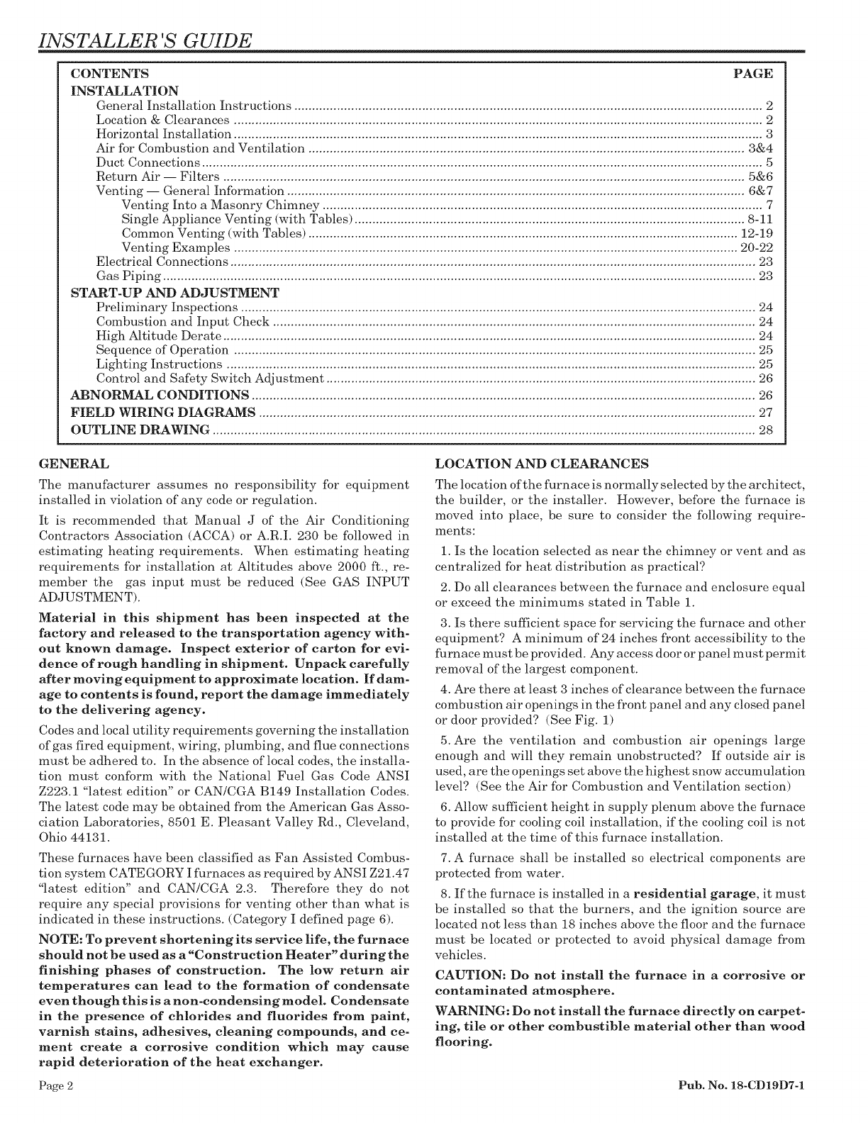
HORIZONTAL INSTALLATION
This furnace may be installed in an attic or crawl space in the
horizontal position by placing the furnace on the left or right
side (as viewed from the front in the upright position). The
horizontal furnace installation in an attic should be on a service
platform large enough to allow for proper clearances on all
sides and service access to the front of the furnace, (See
Clearance Table and Figure 1). If the furnace is suspended, it
must be supported at both ends and in the middle with clearance
allowed for removal of both access doors. Line contact is only
permissible between lines formed by the intersection of the top
and two sides of the furnace casing and the building joists,
studs, or framing.
// // // // //
TYPICAL HORIZONTAL ATTIC INSTALLATION
FIGURE 1
FRONT 3 INCHES (See Note 1
BACK 0 INCHES
TOP 1 INCH
BACK 3 INCH
SIDES 1 INCH
BACK 0 INCHES
SIDES 0 INCHES
NOTES:
(1) Minimum clearance to the front on the *UD140 model is 6 inches.
(2) May be installed on combustible flooring when TYPE B-1 vent pipe is
used.
*-Frst ettermaybe A or T
AIR FOR COMBUSTION AND VENTILATION
Adequate flow of combustion and ventilating air must not be
obstructed from reaching the furnace. Air openings provided in
the furnace casing must be kept free of obstructions which
restrict the flow of air. Airflow restrictions affect the efficiency
and safe operation of the furnace. Keep this in mind should you
choose to remodel or change the area which contains your
furnace. Furnaces must have a free flow of air for proper
performance.
TABLE 1
Provisions for combustion and ventilation air shall be made in
accordance with "latest edition" of Section 5.3, Air for Combus-
tion and Ventilation, of the National Fuel Gas Code, ANSI
Z223.1, or Sections 7.2, 7.3 or 7.4 of CAN/CGA B149 Installation
Codes, and applicable provisions of the local building codes.
Special conditions created by mechanical exhausting of air and
fireplaces must be considered to avoid unsatisfactory furnace
operation.
Furnace locations may be in "confined space" or "unconfined
space". Unconfined space is defined in Table 2 and Figure 2.
These spaces may have adequate air by infiltration to provide
air for combustion, ventilation, and dilution of flue gases.
Buildings with tight construction (for example, weather strip-
ping, heavily insulated, caulked, vapor barrier, etc.), may need
additional air provided as described for confined space.
50 CU. FT. OR MORE
PER 1000 BTU/HR. INPUT
ALL EQUIP. INSTALLED
NO
DOORS
WATER mCLOTHES
_U_AC_
UNCONFINED
FIGURE 2
TABLE 2
MINIMUM AREA IN SQUARE FEET FOR
UNCONFINED SPACE INSTALLATIONS
FURNACE MAXIMUM WITH 8 FOOT CEILING
BTUH /INPUT MINIMUM AREA IN SQUARE FEET
RATING OF UNCONFINED SPACE
40,000
60,000
80,000
100,000
120,000
140,000
250
375
500
325
750
875
Pub. No. 18-CD19D7-1 Page 3
INSTALLER 'S GUIDE
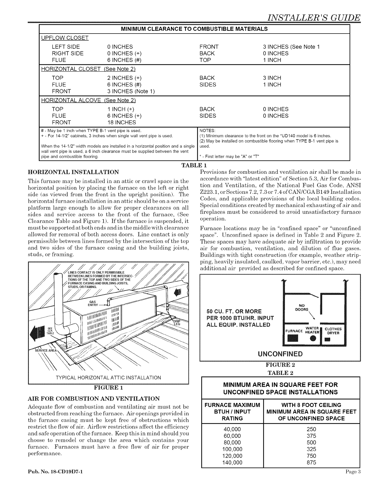
CONFINED
LESS THAN 50 CU. FT.
PER 1000 BTU/HR. iNPUT
ALL EQUIP iNSTALLED
FIGURE 3
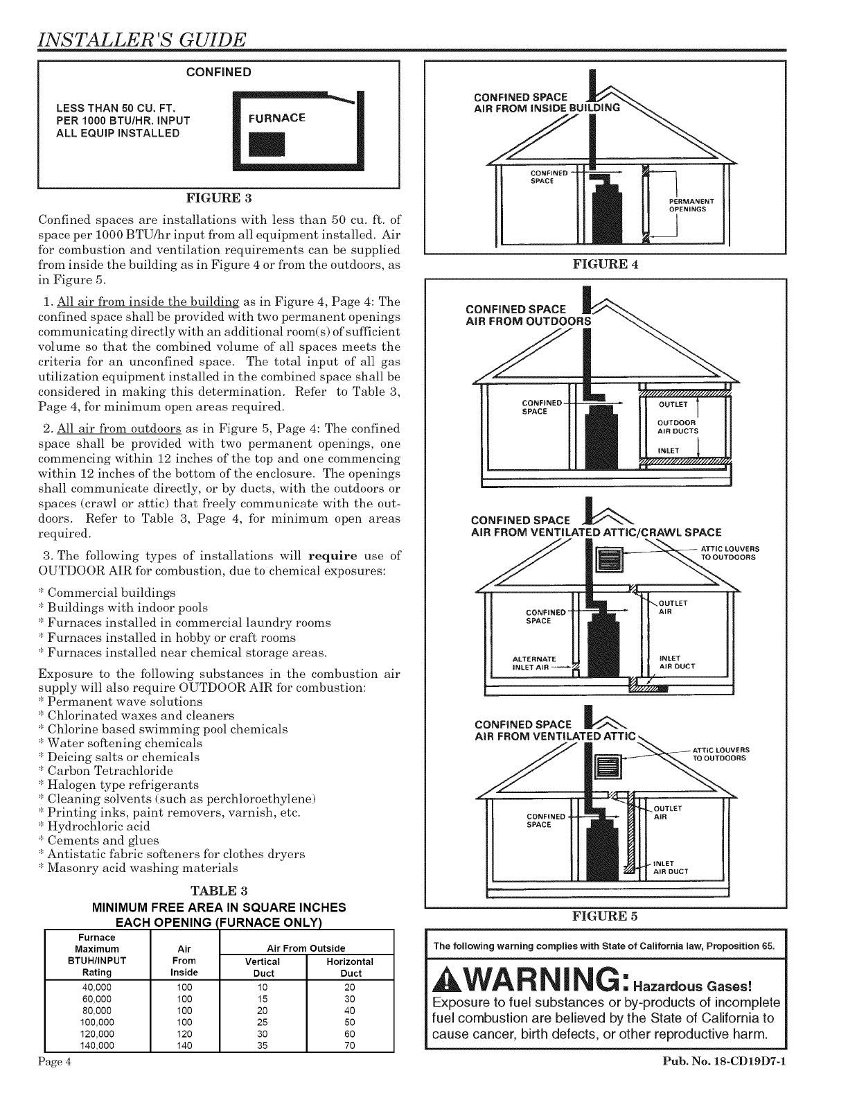
Confined spaces are installations with less than 50 cu. ft. of
space per 1000 BTU/hr input from all equipment installed. Air
for combustion and ventilation requirements can be supplied
from inside the building as in Figure 4 or from the outdoors, as
in Figure 5.
1. All air from inside the building as in Figure 4, Page 4: The
confined space shall be provided with two permanent openings
communicating directly with an additional room(s) of sufficient
volume so that the combined volume of all spaces meets the
criteria for an unconfined space. The total input of all gas
utilization equipment installed in the combined space shall be
considered in making this determination. Refer to Table 3,
Page 4, for minimum open areas required.
2. All air from outdoors as in Figure 5, Page 4: The confined
space shall be provided with two permanent openings, one
commencing within 12 inches of the top and one commencing
within 12 inches of the bottom of the enclosure. The openings
shall communicate directly, or by ducts, with the outdoors or
spaces (crawl or attic) that freely communicate with the out-
doors. Refer to Table 3, Page 4, for minimum open areas
required.
3. The following types of installations will require use of
OUTDOOR AIR for combustion, due to chemical exposures:
* Commercial buildings
* Buildings with indoor pools
* Furnaces installed in commercial laundry rooms
* Furnaces installed in hobby or craft rooms
* Furnaces installed near chemical storage areas.
Exposure to the following substances in the combustion air
supply will also require OUTDOOR AIR for combustion:
* Permanent wave solutions
* Chlorinated waxes and cleaners
* Chlorine based swimming pool chemicals
* Water softening chemicals
* Deicing salts or chemicals
* Carbon Tetrachloride
* Halogen type refrigerants
* Cleaning solvents (such as perchloroethylene)
* Printing inks, paint removers, varnish, etc.
* Hydrochloric acid
* Cements and glues
* Antistatic fabric softeners for clothes dryers
* Masonry acid washing materials
TABLE 3
MINIMUM FREE AREA IN SQUARE INCHES
EACH OPENING
Furnace
Maximum
BTUH/INPUT
Rating
40,000
60,000
80,000
100,000
120,000
140,000
Air
From
Inside
100
100
100
100
120
140
FURNACE ONLY)
Air From Outside
Vertical Horizontal
Duct Duct
10 20
15 30
20 40
25 50
30 60
35 70
Page 4
CONFINED SPACE
AiR FROM iNSiDE BUiLDiNG
ICONFINED --
SPACE
PERMANENT
OPENINGS
FIGURE 4
CONFINED SPACE
AIR FROM OUTDOORS
CONFINED-
SPACE
CONFINED SPACE -_
AiR FROM VENTILATED ATTIC/CRAWL SPACE
ATTIC LOUVERS
TO OUTDOORS
CONFINED"
SPACE
ALTERNATE
iNLET AIR
CONFINED SPACE
AiR FROM
LOUVERS
TO OUTDOORS
CSNFINED-
SPACE
i
FIGURE 5
The following warning complies with Stats of California Mw, Proposition 65.
&WAR NING: .o.o,,oo.
Exposure to fuel substances or by-products of incomplete
fuel combustion are believed by the State of California to
cause cancer, birth defects, or other reproductive harm.
Pub. No. 18-CD19D7-1
DUCT CONNECTIONS
Air duct systems should be installed in accordance with stan-
dards for air conditioning systems, National Fire Protection
Association Pamphlet No. 90. They should be sized in accordance
with ACCA Manual D or whichever is applicable. Check on
controls to make certain they are correct for the electrical supply.
Central furnaces, when used in connection with cooling units,
shall be installed in parallel or on the upstream side of the
cooling units to avoid condensation in the heating element,
unless the furnace has been specifically approved for down-
stream installation. With a parallel flow arrangement, the
dampers or other means used to control flow of air shall be
adequate to prevent chilled air from entering the furnace, and if
manually operated, must be equipped with means to prevent
operation of either unit unless the damper is in full heat or cool
position.
On any job, flexible connections of nonflammable material may
be used for return air and discharge connections to prevent
transmission of vibration. Though these units have been specifi-
cally designed for quiet, vibration free operation, air ducts can
act as sounding boards and could, if poorly installed, amplify the
slightest vibration to the annoyance level.
When the furnace is located in a utility room adjacent to the
living area, the system should be carefully designed with returns
which minimize noise transmission through the return air grille.
Although these winter air conditioners are designed with large
blowers operating at moderate speeds, any blower moving a high
volume of air will produce audible noise-which could be obj ection-
able -when the unit is located very close to a living area. It is often
advisable to route the return air ducts under the floor or through
the attic. Such design permits the installation of air return
remote from the living area (i.e. central hall).
When the furnace is installed so that the supply ducts carry air
circulated by the furnace to areas outside the space containing
the furnace, the return air shall also be handled by a duct(s)
sealed to the furnace and terminating outside the space contain-
ing the furnace.
Where there is no complete return duct system, the return
connection must be run ful! size from the furnace to a
location outside the utility room, basement, attic, or
crawl space.
Do Not install return air through the back of the furnace cabinet.
RETURN AIR DUCT CONNECTION
1. Set the furnace in place.
2. For side return installations, remove the insulation around
the opening in the blower compartment.
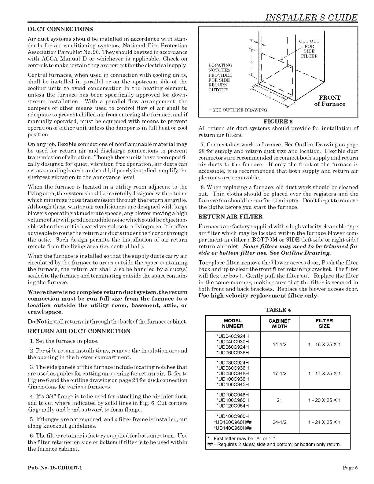
3. The side panels of this furnace include locating notches that
are used as guides for cutting an opening for return air, Refer to
Figure 6 and the outline drawing on page 28 for duct connection
dimensions for various furnaces.
4. If a 3/4" flange is to be used for attaching the air inlet duct,
add to cut where indicated by solid lines in Fig. 6. Cut corners
diagonally and bend outward to form flange.
5. If flanges are not required, and a filter frame is installed, cut
along knockout guidelines.
6. The filter retainer is factory supplied for bottom return. Use
the filter retainer on side or bottom if filter is to be used within
the furnace cabinet.
INSTALLER 'S GUIDE
LOCATING
NOTCHES
PROVIDED
FOR SIDE
RETURN
CUTOUT
* SEE OUTLINE DRAWING
I CUT OUT
FOR
l// SIDE
FILTER
_FRONT
of Furnace
FIGURE 6
All return air duct systems should provide for installation of
return air filters.
7. Connect duct work to furnace. See Outline Drawing on page
28 for supply and return duct size and location. Flexible duct
connectors are recommended to connect both supply and return
air ducts to the furnace. If only the front of the furnace is
accessible, it is recommended that both supply and return air
plenums are removable.
8. When replacing a furnace, old duct work should be cleaned
out. Thin cloths should be placed over the registers and the
furnace fan should be run for 10 minutes. Don't forget to remove
the cloths before you start the furnace.
RETURN AIR FILTER
Furnaces are factory supplied -with a high velocity cleanable type
air filter which may be located within the furnace blower com-
partment in either a BOTTOM or SIDE (left side or right side)
return air inlet. Some filters may need to be trimmed for
side or bottom filter use. See Outline Drawing.
To replace filter, remove the blower access door, Push the filter
back and up to clear the front filter retaining bracket. The filter
will flex (or bow). Gently pull the filter out. Replace the filter
in the same manner, making sure that the filter is secured in
both front and back brackets. Replace the blower access door.
Use high velocity replacement filter only.
TABLE 4
MODEL
NUMBER
*UD040C924H
*UD040C930H
*UD060C924H
*UD060C936H
*UD080C924H
*UD080C936H
*UD080C948H
*UD100C936H
*UD100C945H
CABINET
WIDTH
14-1/2
17-1/2
FILTER
SIZE
1 -16X25X1
1 -17X25X1
*UD100C948H
*UD100C960H 21 1 - 20 X 25 X 1
*UD120C954H
*UD100C960H
*UD120C960H## 24-1/2 1 - 24 X 25 X 1
*UD140C960H##
* - First letter may be "A" or "T"
## - Requires 2 sides; side and bottom; or bottom only return,
Pub. No. 18-CD19D7-1 Page 5
INSTALLER 'S GUIDE
FILTER
-,%
,.\BLOWER
ACCESS
_R
FILTER
RETAINER
Typical Bottom Return Filter
BLOWER
"-'ACCESS
DOOR
Typical Side Return Filter
FIGURE 7A
Typical Horizontal Horizontal Filter
FIGURE 7B
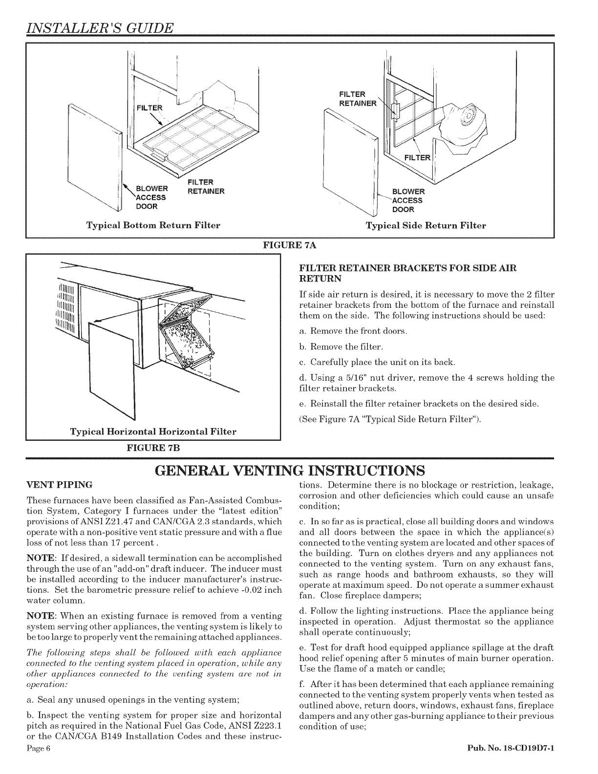
FILTER RETAINER BRACKETS FOR SIDE AIR
RETURN
If side air return is desired, it is necessary to move the 2 filter
retainer brackets from the bottom of the furnace and reinstall
them on the side. The following instructions should be used:
a. Remove the front doors.
b. Remove the filter.
c. Carefully place the unit on its back.
d. Using a 5/16" nut driver, remove the 4 screws holding the
filter retainer brackets.
e. Reinstall the filter retainer brackets on the desired side.
(See Figure 7A "Typical Side Return Filter").
GENERAL VENTING INSTRUCTIONS
VENT PIPING
These furnaces have been classified as Fan-Assisted Combus-
tion System, Category I furnaces under the "latest edition"
provisions of ANSI Z21.47 and CAN/CGA 2.3 standards, which
operate with a non-positive vent static pressure and with a flue
loss of not less than 17 percent.
NOTE: If desired, a sidewall termination can be accomplished
through the use of an "add-on" draft inducer. The indueer must
be installed according to the inducer manufacturer's instruc-
tions. Set the barometric pressure relief to achieve -0.02 inch
water column.
NOTE: When an existing furnace is removed from a venting
system serving other appliances, the venting system is likely to
be too large to properly vent the remaining attached appliances.
The following steps shall be followed with each appliance
connected to the venting system placed in operation, while any
other appliances connected to the venting system are not in
operation:
a. Seal any unused openings in the venting system;
b. Inspect the venting system for proper size and horizontal
pitch as required in the National Fuel Gas Code, ANSI Z223.1
or the CAN/CGA B149 Installation Codes and these instruc-
tions. Determine there is no blockage or restriction, leakage,
corrosion and other deficiencies which could cause an unsafe
condition;
c. In so far as is practical, close all building doors and windows
and all doors between the space in which the appliance(s)
connected to the venting system are located and other spaces of
the building. Turn on clothes dryers and any appliances not
connected to the venting system. Turn on any exhaust fans,
such as range hoods and bathroom exhausts, so they will
operate at maximum speed. Do not operate a summer exhaust
fan. Close fireplace dampers;
d. Follow the lighting instructions. Place the appliance being
inspected in operation. Adjust thermostat so the appliance
shall operate continuously;
e. Test for draft hood equipped appliance spillage at the draft
hood relief opening after 5 minutes of main burner operation.
Use the flame of a match or candle;
f After it has been determined that each appliance remaining
connected to the venting system properly vents when tested as
outlined above, return doors, windows, exhaust fans, fireplace
dampers and any other gas-burning appliance to their previous
condition of use;
Page 6 Pub. No. 18-CD19D7-1
g. If improper venting is observed during any of the above tests,
the venting system must be corrected.
All vent installations must be in accordance with the "latest
edition" provisions of the National Fuel Gas Code, ANSI Z223.1
section 7 and/or CAN/CGA B149 Installation Codes or the Vent
Tables.
The furnace shall be connected to a factory built chimney
or vent complying with a recognized standard, or a
masonry or concrete chimney lined with a lining mate-
rial acceptable to the authority having jurisdiction.
NOTE: Furnace venting into an unlined masonry chim-
ney or concrete chimney is prohibited.
VENTING INTO A MASONRY CHIMNEY
If the chimney is oversized, the liner is inadequate, or flue-gas
condensation is a problem in your area, consider using the
chimney as a pathway or chase for type "B" vent or flexible
vent liner. If flexible liner material is used, size the vent using
the "B" vent tables, then reduce the maximum capacity by 20%
(multiply 0.80 times the maximum capacity).
TABLE 5
MASONRY CHIMNEY VENTING
Type Furnace
Single Fan
Assist
Fan Assist
+
Fan Assist
Fan Assist
+
Natural
Tile Lined Chimney
Internal External "B" Vent
No No Yes
No No Yes
Yes No Yes
Chimney Lining
Flexible Metal
Liner
*Yes
:l¢ye s
:ltye S
* Flexible chinmey liner size is determined by using the type "B" vent size for the
available BTUH input, then reducing the maximum capacity by 20% (multiply
maximum capacity times 0.80). The rninin_um capacity is the same as shown in
the "B" vent tables.
Internal Masonry Chimneys
Venting of fan assisted appliances into a lined, internal ma-
sonry chimney is allowed only if it is common vented with at
least one natural draft appliance; OR, if the chimney is lined
with type "B", double wall vent or suitable flexible liner mate-
rial, (See Table 5).
NOTE: The chimney liner must be thoroughly inspected to
insure no cracks or other potential areas for flue gas leaks are
present in the liner. Liner leaks will result in early deteriora-
tion of the chimney.
External Masonry Chimney
Venting of fan assisted appliances into external chimneys (one
or more walls exposed to outdoor temperatures), requires the
chimney be lined with type "B", double wall vent or suitable
flexible chimney liner material. This applies in all combina-
tions of common venting as well as for fan assisted appliances
vented alone.
The following installation practices are recommended to mini-
mize corrosion caused by condensation of flue products in the
furnace and flue gas system.
1. Avoid an excessive number of bends.
2. Horizontal runs should pitch upward at least 1/4" per foot.
3. Horizontal runs should be as short as possible.
4. All vent pipe or connectors should be securely supported and
must be inserted into, but not beyond the inside wall at the
chimney vent.
Pub. No. 18-CD19D7-1
INSTALLER 'S GUIDE
5. When vent connections must pass through walls or partitions
of combustible material, a thimble must be used and installed
according to local codes.
6. Vent pipe through the roof should be extended to a height
determined by National Fuel Gas Code or local codes. It should
be capped properly to prevent rain -water from entering the vent.
Roof exit should be waterproofed.
7. Use type "B" double -wall vent when vent pipe is routed
through cool spaces, (below 60°F).
8. Where long periods of airflow are desired for comfort, use
long fan cycles instead of continuous airflow.
9. Apply other good venting practices as stated in the venting
section of the National Fuel Gas Code ANSI Z223.1 "latest
edition".
10. Vent connectors serving appliance vented by natural
draft or non-positive pressure shall not be connected
into any portion of a mechanized draft system operating
under positive pressure.
11. Horizontal pipe runs must be supported by hangers, straps
or other suitable material in intervals at a minimum of every
3 feet of pipe.
12. A furnace shall not be connected to a chimney or flue
serving a separate appliance designed to burn solid fuel.
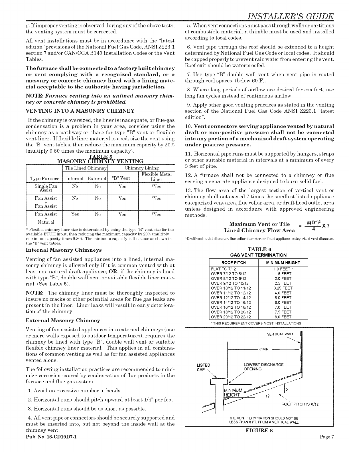
13. The flow area of the largest section of vertical vent or
chimney shall not exceed 7 times the smallest listed appliance
categorized vent area, flue collar area, or draft hood outlet area
unless designed in accordance with approved engineering
methods.
Maximum Vent or Tile _(D*) 2
Lined Chimney Flow Area = _ X 7
*Draf_hood outlet diameter, flue collar diameter, or listed appliance categorized vent diameter.
TABLE 6
GAS VENT TERMINATION
ROOF PITCH
FLAT TO 7/12
OVER 7112 TO 8/12
OVER 8112 TO 9/12
OVER 9/12 TO 10/12
OVER 10/12 TO 11/12
OVER 11/12 TO 12/12
OVER 12/12 TO 14/12
OVER 14/12 TO 16/12
OVER 16/12 TO 18/12
OVER 16/12 TO 20/12
OVER 20/12 TO 22/12
MINIMUM HEIGHT
1.0 FEET *
1.5 FEET
2.0 FEET
2.5 FEET
3.25 FEET
4.0 FEET
5.0 FEET
6.0 FEET
7.0 FEET
7.5 FEET
8.0 FEET
* THIS REQUIREMENT COVERS MOST INSTALLATIONS
LISTED
CAP
VERTICAL WALL
8' MIN.
LOWEST DISCHARGE
OPENING
(
12 _'.\
ROOF PITCH iS )(//12
THE VENT TERMINATION SHOULD NOT BE
LESS THAN 8 FT FROM A VERTICAL WALL
FIGURE 8
Page 7
INSTALLER 'S GUIDE
SIZING OF VENTING SYSTEMS SERVING APPLI-
ANCES EQUIPPED WITH DRAFT HOODS AND APPLI-
ANCES LISTED FOR USE WITH TYPE B VENTS
Definitions. The following definitions apply to tables in
the venting portion of this Installer's Guide:
Fan-Assisted Combustion System - An appliance
equipped with an integral mechanical means to either draw
or force products of combustion through the combustion
chamber and/or heat exchanger.
FAN Min. - The minimum appliance input rating of a
Category I appliance with a fan-assisted combustion system
that could be attached to the vent.
FAN Max. - The maximum appliance input rating of a
Category I appliance with a fan-assisted combustion system
that could be attached to the vent.
NAT Max. - The maximum input rating of a Category I
appliance equipped with a draft hook that could be attached
to the vent. There are no minimum appliance input ratings
for draft hood equipped appliances.
FAN+FAN - The maximum combined appliance input
rating of one or more fan-assisted appliances attached to the
common vent.
FAN+NAT - The maximum combined appliance input
rating of one or more fan-assisted appliances attached to the
common vent.
NAT+NAT - The maximum combined input rating of two
or more draft hood equipped appliances attached to the
common vent.
NR - Vent configuration is not recommended due to
potential for condensate formation and/or pressurization of
the venting system.
NA- Vent configuration is not applicable due to physical
or geometric constraints.
Notes for Single Appliance Vents: (See Tables J-1 to J-5)
!.
2.
If the vent size determined from the tables is smaller than
the appliance draft hood outlet or flue collar, the smaller
size shall be permitted to be used, provided:
(a) The total vent height ('T') is at least i0 feet;
(b) Vents for appliance draft hood outlets or flue collars
12 inches in diameter or smaller are not reduced more
than one table size;
(c) Vents for appliance draft hood outlets or flue collars
above 12 inches in diameter are not reduced more than
two table sizes;
(d) The maximum capacity listed in the tables for a fan-
assisted appliance is reduced by 10 percent (.09 x
maximum table capacity);
(e) The draft hood outlet is greater than 4 inches in
diameter. Do not connect a 3 inch diameter vent to a
4 inch diameter draft hood outlet. This provision ("e")
shall not apply to fan-assisted appliances.
Single appliance venting configurations with zero (0")
lateral lengths in Tables J-l, J-2 and J-5 shall have no
3.
elbows in the venting system. For vent configurations
with lateral lengths, the venting tables include allowance
for two 90 degree (1.57 rad) elbows. For each additional 90
degree (1.57 rad) elbow, or equivalent beyond two, the
maximum capacity listed in the venting table should be
reduced by 10 percent (0.90 x maximum table capacity).
Note: Two 45 degree (0.79 rad) elbows are equivalent to
one 90 degree (1.57 rad) elbow.
Zero ("0") lateral ("L") shall apply only to a straight
vertical-vent attachment to a top outlet draft hood or flue
collar.
4.
5.
Sea-level input ratings shall be used when determining
maximum capacity for high-altitude installation. Actual
input (derated for altitude) shall be used to determine
minimum capacity for high altitude installation.
Numbers followed by asterisk (*) in Tables J-3, J-4 and J-5
indicate the possibility of continuous condensation,
depending on locality. Consult local serving gas supplier
or local codes.
6.
7.
8.
9.
10.
11.
12.
For appliances with more than one input rate, the mini-
mum vent capacity determined from the tables shall be
greater than the highest appliance input rating.
Listed corrugated chimney-liner systems in masonry
chimneys shall be sized by using Tables J-1 or J-2 for
Type B vents with the maximum capacity reduced by
20 percent (0.80 maximum table capacity) and the mini-
mum capacity as shown in Tables J- 1 and J-2. Corrugated
metal venting systems installed with bends or offsets shall
have their maximum capacity reduces. (See Note 2).
If the vertical vent has a larger diameter than the vent
connector, use the vertical vent-connector diameter to
determine the minimum vent capacity and the connector
diameter to determine the maximum vent capacity. The
flow area of the vertical vent shall not exceed seven times
the flow area of the listed appliance categorized vent area,
flue collar area, or draft hood outlet area, unless desig-
nated in accordance with approved engineering methods.
The tables included in this part shall be used for chim-
neys and vents not exposed to the outdoors below the roof
line. Exterior chimneys or vents exposed to the outdoors
below the roof line may experience continuous condensa-
tion depending on locality. Consult local serving gas
suppliers, or the authority having jurisdiction. A Type B
vent or listed chimney lining system passing through an
otherwise unused masonry chimney flue shall be consid-
ered to be an interior vent system.
Vent connectors shall not be sized upward more than two
sizes greater than the appliance categorized vent diam-
eter, flue collar diameter, or draft hood outlet diameter.
In a single run of vent or vent connector, more than one
diameter and type shall be permitted to be used provided
that all the sizes and types are permitted by the tables.
Interpolation shall be permitted in calculating capacities
for vent dimensions which fall between table entries.
13. Extrapolation beyond the table entries shall not be per-
mitted.
SEE EXAMPLES ON PAGES 20 TO 22.
Page 8 Pub. No. 18-CD19D7-1
INSTALLER 'S GUIDE
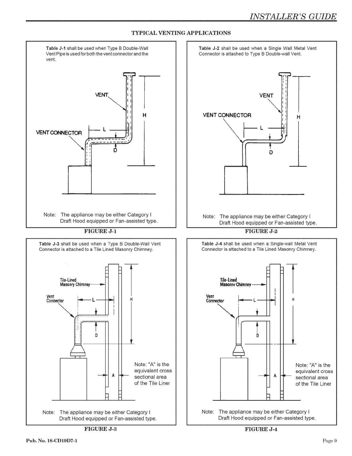
TYPICAL VENTING APPLICATIONS
Table J-1 shall be used when Type B Double-Wall
Vent Pipe is used for both the vent connector and the
vent.
VENT CONNECTOR
\,
Note: The appliance may be either Category I
Draft Hood equipped or Fan-assisted type.
FIGURE J-1
Table J-3 shall be used when a Type B Double-Wall Vent
Connector is attached to a Tile Lined Masonry Chimney.
Tile-Lined
MasonryChirnney---m_
Vent
Connecter _ L-- H
Note: "A" is the
equivalent cross
sectional area
of the Tile Liner
Note: The appliance may be either Category I
Draft Hood equipped or Fan-assisted type.
FIGURE J-3
Table J-2 shall be used when a Single Wall Metal Vent
Connector is attached to Type B Double-wall Vent.
VENT CONNECTOR
::Z-:
VENT
\
II
D
H
Note: The appliance may be either Category I
Draft Hood equipped or Fan-assisted type.
FIGURE J-2
Table J-4 shall be used when a Single-wall Metal Vent
Connector is attached to a Tile Lined Masonry Chimney,
Note: "A" is the
equivalent cross
sectional area
of the Tile Liner
Note: The appliance may be either Category I
Draft Hood equipped or Fan-assisted type.
FIGURE J-4
Pub. No. 18-CD19D7-1 Page 9
INSTALLER 'S GUIDE
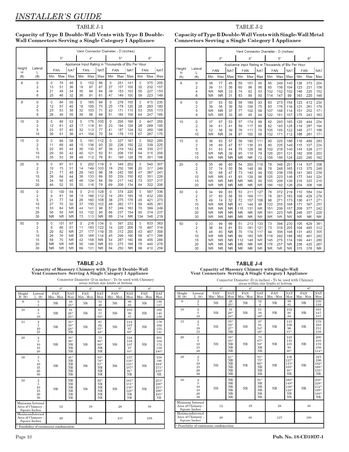
TABLE J-1
Capacity of Type B Double-Wall Vents with Type B Double-
Wall Connectors Serving a Single Category I Appliance
TABLE J-2
Capacity of Type B Double-Wall Vents with Single-Wall Metal
Connectors Serving a Single Category I Appliance
Height Lateral
H L
(fl) (_)
6 O
2
4
6
8 O
2
5
8
10 O
2
5
10
15 O
2
5
10
15
2O O
2
5
10
15
20
3O O
2
5
10
15
20
30
5O O
2
5
10
15
20
30
Vent Connector Diameter - D (inches)
3,, I 4,, I 5,, I °"
Appliance Input Rating in Thousands of Btu Per Hour
FAN NAT _ NAT _ NAT _ NAT
Min Max Max Max Max I Min Max Max
0 78 46 O 152 86 0 251 141 0 375 205
13 51 36 18 97 67 27 157 105 32 232 157
21 49 34 30 94 64 39 153 103 50 227 153
25 46 32 36 91 61 47 149 100 59 223 149
0 84 50 0 165 94 0 276 155 0 415 235
12 57 40 16 109 75 25 178 120 28 263 180
23 53 38 32 103 71 42 171 115 53 255 173
28 49 35 39 98 66 51 164 109 64 247 165
0 88 53 0 175 100 0 295 166 0 447 255
12 61 42 17 118 81 23 194 129 26 289 195
23 57 40 32 113 77 41 187 124 52 280 188
30 51 36 41 104 70 54 176 115 67 267 175
0 94 58 0 191 112 0 327 187 0 502 285
11 69 48 15 136 93 20 226 150 22 339 225
22 65 44 30 130 87 39 219 142 49 330 217
29 59 42 40 121 82 51 206 135 64 315 208
35 53 39 48 112 76 61 195 128 76 301 198
0 97 61 0 202 119 0 349 202 0 540 307
10 75 51 14 149 100 18 250 166 20 377 249
21 71 48 29 143 96 38 242 160 47 367 241
28 64 44 38 133 89 50 229 150 62 351 228
34 58 40 46 124 84 59 217 142 73 337 217
48 52 35 55 116 78 69 206 134 84 322 206
0 100 64 0 213 128 0 374 220 0 587 336
9 81 56 13 166 112 14 283 185 18 432 280
21 77 54 28 160 108 36 275 176 45 421 273
27 70 50 37 150 102 48 262 171 59 405 261
33 64 NR 44 141 96 57 249 163 70 389 249
56 58 NR 53 132 90 66 237 154 80 374 237
NR NR NR 73 113 NR 88 214 NR 104 346 219
0 101 67 g 216 134 0 397 232 0 633 363
8 86 61 11 183 122 14 320 206 15 497 314
20 82 NR 27 177 119 35 312 200 43 487 308
26 76 NR 35 168 114 45 299 190 56 471 298
59 70 NR 42 158 NR 54 287 180 66 455 288
NR NR NR 50 149 NR 63 275 169 76 440 278
NR NR NR 69 131 NR 84 250 NR 99 410 259
Height Lateral
H L
(ft) (ft)
6 0
2
4
6
8 0
2
5
8
I0 0
2
5
10
15 0
2
5
10
15
2O 0
2
5
10
15
2O
30 0
2
5
10
15
20
30
5O 0
2
5
10
15
20
30
Vent Connector Diameter - D (inches)
3,, I 4,, I 5,, I °"
Appliance Input Rating in Thousands of Btu Per Hour
!A'_I"AT F I__ __INAT
Min Max/ Max IMin Max I MaxIMin Max I MaxIMin Max I Max
38 77 45 59 151 85 85 249 140 126 373 204
39 51 36 60 96 66 85 156 104 123 231 156
NR NR 33 74 92 63 102 152 102 146 225 152
NR NR 31 83 89 60 114 147 99 163 220 148
37 83 50 58 164 93 83 273 154 123 412 234
39 56 39 59 108 75 83 176 119 121 261 179
NR NR 37 77 102 69 107 168 114 151 252 171
NR NR 33 90 95 64 122 161 107 175 243 163
37 87 53 57 174 99 82 293 165 120 444 254
39 61 41 59 117 80 82 193 128 119 287 194
52 56 39 76 111 76 105 185 122 148 277 186
NR NR 34 97 100 68 132 171 112 188 261 171
36 93 57 56 190 111 80 325 186 116 499 283
38 69 47 57 136 93 80 225 149 115 337 224
51 63 44 75 128 86 102 216 140 144 326 217
NR NR 39 95 116 79 128 201 131 182 308 203
NR NR NR NR NR 72 158 186 124 220 290 192
35 96 60 54 200 118 78 346 201 114 537 306
37 74 50 56 148 99 78 248 165 113 375 248
50 68 47 73 140 94 100 239 158 141 363 239
NR NR 41 93 129 86 125 223 146 177 344 224
NR NR NR NR NR 80 155 208 136 216 325 210
NR NR NR NR NR NR 186 192 126 254 306 196
34 99 63 53 211 127 76 372 219 110 584 334
37 80 56 55 164 111 76 281 183 109 429 279
49 74 52 72 157 106 98 271 173 136 417 271
NR NR NR 91 144 98 122 255 168 171 397 257
NR NR NR 115 131 NR 151 239 157 208 377 242
NR NR NR NR NR NR 181 223 NR 246 357 228
NR NR NR NR NR NR NR NR NR NR NR NR
33 99 66 51 213 133 73 394 230 105 629 361
36 84 61 53 181 121 73 318 205 104 495 312
48 80 NR 70 174 117 94 308 198 131 482 305
NR NR NR 89 160 NR 118 292 186 162 461 292
NR NR NR 112 148 NR 145 275 174 199 441 280
NR NR NR NR NR NR 176 257 NR 236 420 267
NR NR NR NR NR NR NR NR NR 315 376 NR
TABLE J-3
Capacity of Masonry Chimney with Type B Double-Wall
Vent Connectors Serving A Single Category I Appliance
Connector Diameter (D in inches) - To be used with Chimney
areas within size limits at bottom
3" 4" 5" 6"
Height Lateral FAN NAT FAN NAT FAN NAT FAN NAT
H (ft) L (R) Min- Max Max Min- Max Max Min- Max Max Min- Max Max
6 2 NR 28 NR 52 NR 86 NR 130
5 25 _ 49 82 117
10 2 31 61 103 162
5 NR 28* NR 57 NR 96 NR 148
10 25 _ 50* 87 139
15 2 35 _ 67 114 179
5 NR 33* NR 62 NR 107 NR 164
10 28 _ 55* 97 153
15 NR 48* 89* 141
20 2 38" 74 124 201
5 36 _ 68 _ 116 184
10 NR NR NR 60* NR 107 NR 172
15 NR NR 97 159
20 NR NR 83* 148"
30 2 41" 82* 137 216
5 NR 76" 128" 198
10 NR 67* 115" 184"
NR NR NR NR
15 NR NR 107" 171"
20 NR NR 91" 159"
30 NR NR NR NR
50 2 NR 92* 161" 251"
5 NR NR 151" 230*
10 NR NR NR NR NR 138" NR 215"
15 NR NR 128" 199"
20 NR NR NR 185"
30 NR NR NR NR
Minimum Internal
Area of Chimney - 12 19 28 38
Square Inches
MaximumInternal
Area of Chimney - 49 88 137 198
Square Inches
* Possibility of continuous condensation
TABLE J-4
Capacity of Masonry Chimney with Single-Wall
Vent Connectors Serving A Single Category I Appliance
Connector Diameter (D in inches) - To be used with Chimney
areas within size limits at bottom
3" 4" 5" 6"
Height Lateral FAN NAT FAN NAT FAN NAT FAN NAT
H fit) L (R) Min - Max Max Min - Max Max Min - M_x Max Min - M_x Max
6 2 28 52 86 130
NR NR NR NR
5 25' 4 81 116
10 2 31 61 102 161
5 NR 28 NR 56 NR 95 NR 147
10 24* 49: 86 137
15 2 35' 67 113 178
5 32 _ 61 106 163
NR NR NR NR
10 27 54* 96 151
15 NR 46' 87* 138
20 2 38 73 123 200
5 35' 67' 115 183
10 NR NR NR 59' NR 105 NR 170
15 NR NR 95 156
20 NR NR 80* 144"
30 2 41 81 136 215
5 NR 75* 127 196
10 NR 66* 113' 182'
NR NR NR NR
15 NR NR 105' 168
20 NR NR 88* 155'
30 NR NR NR NR
50 2 NR 91 160' 250'
5 NR NR 149' 228
10 NR NR NR NR NR 136_ NR 212'_
15 NR NR 124" 195'
20 NR NR NR 180'
30 NR NR NR NR
Minimum Internal
Area of Chimney - 12 19 28 38
Square Inches
MaximumInternal
Area of Chimney - 49 88 137 198
Square Inches
Possibility of continuous condensation
Page I0 Pub. No. 18-CD19D7-1
INSTALLER 'S GUIDE
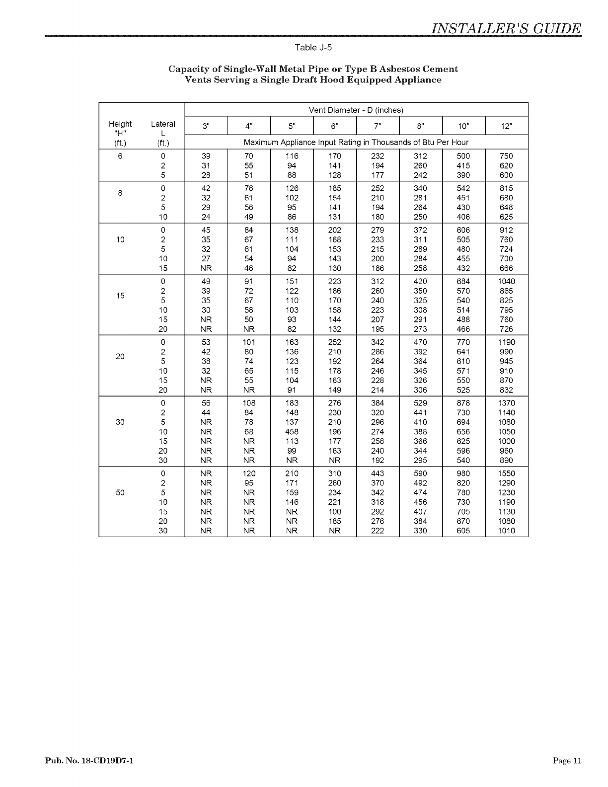
Table J-5
Capacity of Single-Wall Metal Pipe or Type B Asbestos Cement
Vents Serving a Single Draft Hood Equipped Appliance
Vent Diameter - D (inches)
Height 3" 4" 5" 6" 7" 8" 10" 12"
"H"
(ft.) Maximum Appliance Input Rating in Thousands of Btu Per Hour
6 7O
55
5t
76
8 61
56
49
84
10
15
20
30
50
Lateral
L
(ft.)
0
2
5
0
2
5
10
0
2
5
10
15
0
2
5
10
15
2O
0
2
5
10
15
2O
0
2
5
10
15
2O
3O
0
2
5
10
15
2O
3O
39
31
28
42
32
29
24
45
35
32
27
NR
49
39
35
30
NR
NR
53
42
38
32
NR
NR
56
44
NR
NR
NR
NR
NR
NR
NR
NR
NR
NR
NR
NR
67
61
54
46
91
72
67
58
50
NR
101
80
74
65
55
NR
108
84
78
68
NR
NR
NR
120
95
NR
NR
NR
NR
NR
116
94
88
126
102
95
86
138
111
104
94
82
15t
122
110
103
93
82
163
136
123
115
104
91
183
148
137
458
113
99
NR
210
171
159
146
NR
NR
NR
170
14t
128
185
154
14t
131
2O2
168
153
143
130
223
186
170
158
144
132
252
210
192
178
163
149
276
230
210
196
177
163
NR
310
260
234
221
100
185
NR
232
194
177
252
210
194
180
279
233
215
2OO
186
312
26O
24O
223
2O7
195
342
286
264
246
228
214
384
32O
296
274
258
24O
192
443
37O
342
318
292
276
222
312
260
242
340
281
264
250
372
311
289
284
258
420
350
325
308
291
273
470
392
364
345
326
306
529
44t
410
388
366
344
295
590
492
474
456
407
384
330
5OO
415
39O
542
451
43O
4O6
6O6
5O5
48O
455
432
684
57O
540
5t4
488
466
770
641
610
571
550
525
878
730
694
656
625
596
540
980
820
780
730
705
670
605
75O
62O
6OO
815
68O
648
625
912
76O
724
7OO
666
1040
865
825
795
760
726
1190
990
945
910
870
832
1370
1140
1080
1050
1000
960
890
1550
1290
1230
1190
1130
1080
1010
Pub. No. 18-CD19D7-1 Page 11
INSTALLER 'S GUIDE
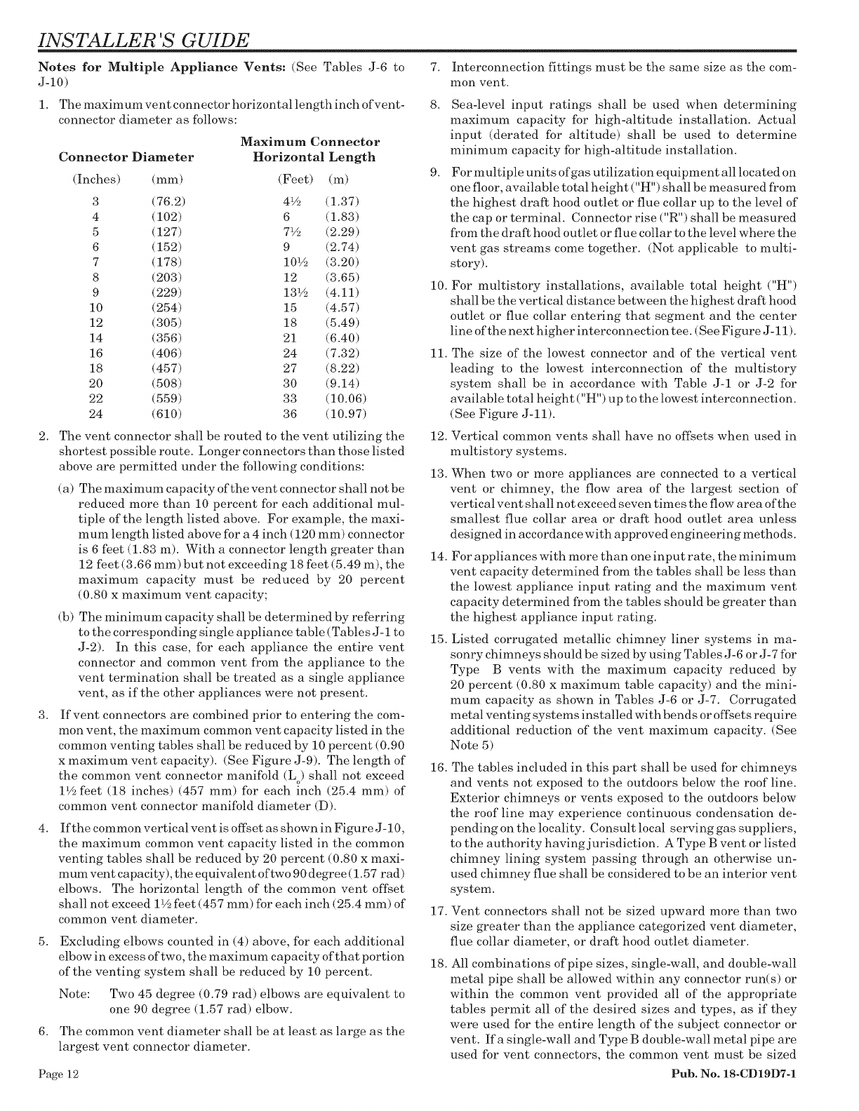
Notes for Multiple Appliance Vents: (See Tables J-6 to
J-10)
1, The maximum vent connector horizontal length inch of vent-
connector diameter as follows:
Connector Diameter
(Inches) (mm)
Maximum Connector
Horizontal Length
(Feet) (m)
3 (76.2) 4½ (1.37)
4 (102) 6 (1.83)
5 (127) 71½ (2.29)
6 (152) 9 (2.74)
7 (178) 101½ (3.20)
8 (203) 12 (3.65)
9 (229) 131½ (4.11)
10 (254) 15 (4.57)
12 (305) 18 (5.49)
14 (356) 21 (6.40)
16 (406) 24 (7.32)
18 (457) 27 (8.22)
20 (508) 30 (9.14)
22 (559) 33 (10.06)
24 (610) 36 (10.97)
2. The vent connector shall be routed to the vent utilizing the
shortest possible route. Longer connectors than those listed
above are permitted under the following conditions:
(a) The maximum capacity of the vent connector shall not be
reduced more than I0 percent for each additional mul-
tiple of the length listed above. For example, the maxi-
mum length listed above for a 4 inch (120 mm) connector
is 6 feet (1.83 m). With a connector length greater than
12 feet (3.66 mm) but not exceeding 18 feet (5.49 m), the
maximum capacity must be reduced by 20 percent
(0.80 x maximum vent capacity;
(b) The minimum capacity shall be determined by referring
to the corresponding single appliance table (Tables J-1 to
J-2). In this case, for each appliance the entire vent
connector and common vent from the appliance to the
vent termination shall be treated as a single appliance
vent, as if the other appliances were not present.
3. If vent connectors are combined prior to entering the com-
mon vent, the maximum common vent capacity listed in the
common venting tables shall be reduced by 10 percent (0.90
x maximum vent capacity). (See Figure J-9). The length of
the common vent connector manifold (L o) shall not exceed
1½ feet (18 inches) (457 mm) for each inch (25.4 mm) of
common vent connector manifold diameter (D).
4, If the common vertical vent is offset as shown in Figure J-10,
the maximum common vent capacity listed in the common
venting tables shall be reduced by 20 percent (0.80 x maxi-
mum vent capacity), the equivalent of two 90 degree (1.57 rad)
elbows. The horizontal length of the common vent offset
shall not exceed 1½ feet (457 mm) for each inch (25.4 mm) of
common vent diameter.
5. Excluding elbows counted in (4) above, for each additional
elbow in excess of two, the maximum capacity of that portion
of the venting system shall be reduced by 10 percent.
Note: Two 45 degree (0.79 rad) elbows are equivalent to
one 90 degree (1.57 rad) elbow.
6. The common vent diameter shall be at least as large as the
largest vent connector diameter.
Page 12
7. Interconnection fittings must be the same size as the com-
mon vent.
8. Sea-level input ratings shall be used when determining
maximum capacity for high-altitude installation. Actual
input (derated for altitude) shall be used to determine
minimum capacity for high-altitude installation.
9. For multiple units ofgas utilization equipment all located on
one floor, available total height ("H") shall be measured from
the highest draft hood outlet or flue collar up to the level of
the cap or terminal. Connector rise ("R") shall be measured
from the draft hood outlet or flue collar to the level where the
vent gas streams come together. (Not applicable to multi-
story).
10. For multistory installations, available total height ("H")
shall be the vertical distance between the highest draft hood
outlet or flue collar entering that segment and the center
line of the next higher interconnection tee. (See Figure J- 11).
11. The size of the lowest connector and of the vertical vent
leading to the lowest interconnection of the multistory
system shall be in accordance with Table J-1 or J-2 for
available total height ("H") up to the lowest interconnection.
(See Figure J-11).
12. Vertical common vents shall have no offsets when used in
multistory systems.
13. When two or more appliances are connected to a vertical
vent or chimney, the flow area of the largest section of
vertical vent shall not exceed seven times the flow area of the
smallest flue collar area or draft hood outlet area unless
designed in accordance with approved engineering methods.
14. For appliances with more than one input rate, the minimum
vent capacity determined from the tables shall be less than
the lowest appliance input rating and the maximum vent
capacity determined from the tables should be greater than
the highest appliance input rating.
15. Listed corrugated metallic chimney liner systems in ma-
sonry chimneys should be sized by using Tables J-6 or J-7 for
Type B vents with the maximum capacity reduced by
20 percent (0.80 x maximum table capacity) and the mini-
mum capacity as shown in Tables J-6 or J-7. Corrugated
metal venting systems installed with bends or offsets require
additional reduction of the vent maximum capacity. (See
Note 5)
16. The tables included in this part shall be used for chimneys
and vents not exposed to the outdoors below the roof line.
Exterior chimneys or vents exposed to the outdoors below
the roof line may experience eontinuous condensation de-
pending on the locality. Consult local serving gas suppliers,
to the authority havingjurisdietion. A Type B vent or listed
chimney lining system passing through an otherwise un-
used chimney flue shall be considered to be an interior vent
system.
17. Vent connectors shall not be sized upward more than two
size greater than the appliance categorized vent diameter,
flue collar diameter, or draft hood outlet diameter.
18. All combinations of pipe sizes, single-wall, and double-wall
metal pipe shall be allowed within any connector run(s) or
within the common vent provided all of the appropriate
tables permit all of the desired sizes and types, as if they
were used for the entire length of the subject connector or
vent. Ifa single-wall and Type B double-wall metal pipe are
used for vent connectors, the common vent must be sized
Pub. No. 18-CD19D7-1
INSTALLER 'S GUIDE
using Table J-7 or J-9 as appropriate.
19. The draft hood outlet or flue collar of the smallest input
appliance shall be located closest to, or under, the common
vent.
20. When a table permits more than one diameter of pipe to be
used for a connector or vent, all the permitted sizes shall be
permitted to be used.
Note: In general, it is preferable to use the smallest
diameter permitted to minimize heat loss.
21. Interpolation shall be permitted in calculating capacities
for vent dimensions which fall between table entries.
22. Extrapolation beyond the table entries shall not be permit-
ted.
SEE EXAMPLES ON PAGES 20 TO 22.
TYPICAL COMMON VENTING APPLICATIONS
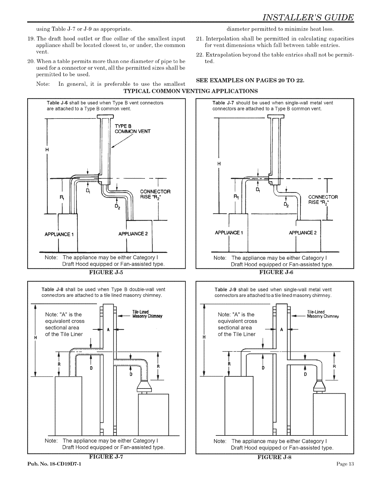
Table J-6 shall be used when Type B vent connectors
are attached to a Type B common vent.
C="=3
'-IF TYPE B N VENT
,17
--IIIL
CONNECTOR
APPLIANCE2
1
The appliance may be either Category I
Draft Hood equipped or Fan-assisted type.
FIGURE J-5
APPLIANCE1
Note:
Table J-7 should be used when single-wall metal vent
connectors are attached to a Type B common vent.
I
H
CONNECTOR
RISE"R2"
APPLIANCE1
1
Note:
APPLIANCE2
I
The appliance may be either Category I
Draft Hood equipped or Fan-assisted type.
FIGURE J-6
Table J-8 shall be used when Type B double-wall vent
connectors are attached to a tile lined masonry chimney.
Note: "A" is the
equivalent cross
sectional area
of the Tile Liner
R
Tile-Lined
MasonryChimney
t
R
__L
Note: The appliance may be either Category I
Draft Hood equipped or Fan-assisted type.
FIGURE J-7
Pub. No. 18-CD19D7-1
H
Table J-9 shall be used when single-wall metal vent
connectors are attached to a tile lined masonry chimney.
Tile-Lined
Note: "A" is the MasenryChimney
equivalent cross
sectional area A
of the Tile Liner
t
R
_1
Note: The appliance may be either Category I
Draft Hood equipped or Fan-assisted type.
FIGURE J-8
Page 13
INSTALLER 'S GUIDE
TYPICAL COMMON VENTING APPLICATIONS (Cont.)
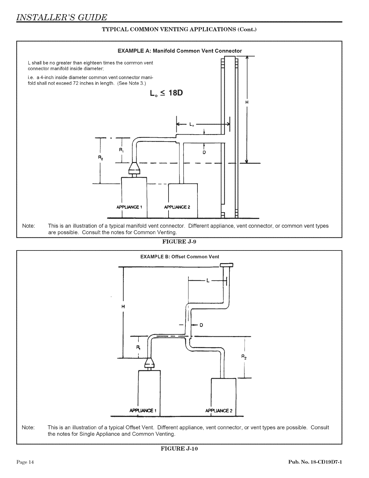
EXAMPLE A: Manifold Common Vent Connector
L shall be no greater than eighteen times the common vent
connector manifold inside diameter;
i.e. a 4-inch inside diameter common vent connector mani-
fold shall not exceed 72 inches in length. (See Note 3.)
Lo < 18D
Lo
lm
R
Note: This is an illustration of a typical manifold vent connector. Different appliance, vent connector, or common vent types
are possible. Consult the notes for Common Venting.
FIGURE J-9
EXAMPLE B: Offset Common Vent
Note: This is an illustration of a typical Offset Vent. Different appliance, vent connector, or vent types are possible. Consult
the notes for Single Appliance and Common Venting.
FIGURE J-10
Page 14 Pub. No. 18-CD19D7-1
INSTALLER 'S GUIDE
TYPICAL VENTING APPLICATIONS (Cont.)
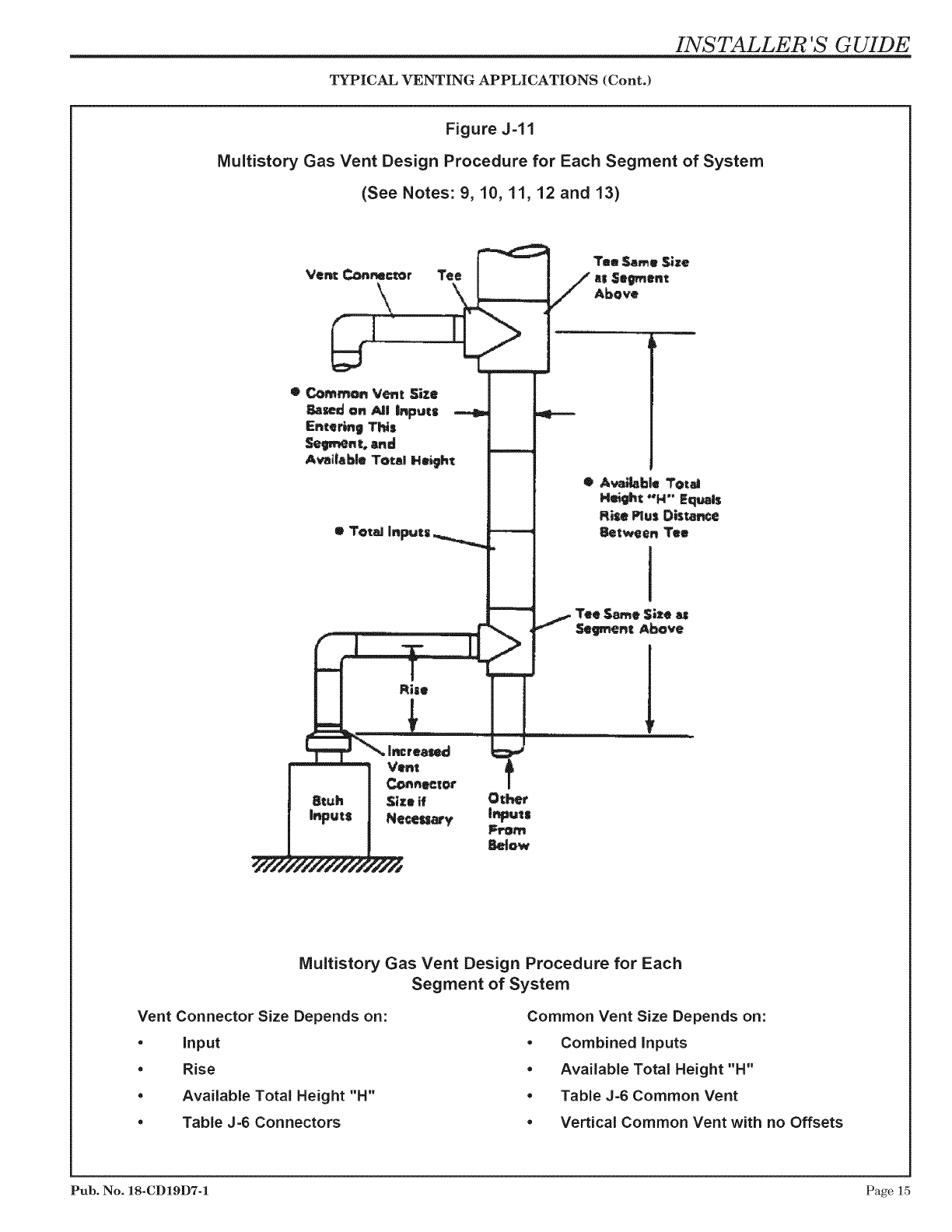
Figure J-I 1
Multistory Gas Vent Design Procedure for Each Segment of System
(See Notes: 9, 10, 11, 12 and 13)
Tn Same $;ze
as Se_ent
Above
Multistory Gas Vent Design Procedure for Each
Segment of System
Vent Connector Size Depends on:
* Input
*Rise
* Available Total Height "H"
* Table J-6 Connectors
Common Vent Size Depends on:
* Combined Inputs
* Available Total Height "H"
* Table J-6 Common Vent
* Vertical Common Vent with no Offsets
Pub. No. 18-CD19D7-1 Page 15
INSTALLER 'S GUIDE
TYPICAL VENTING APPLICATIONS (Cont.)
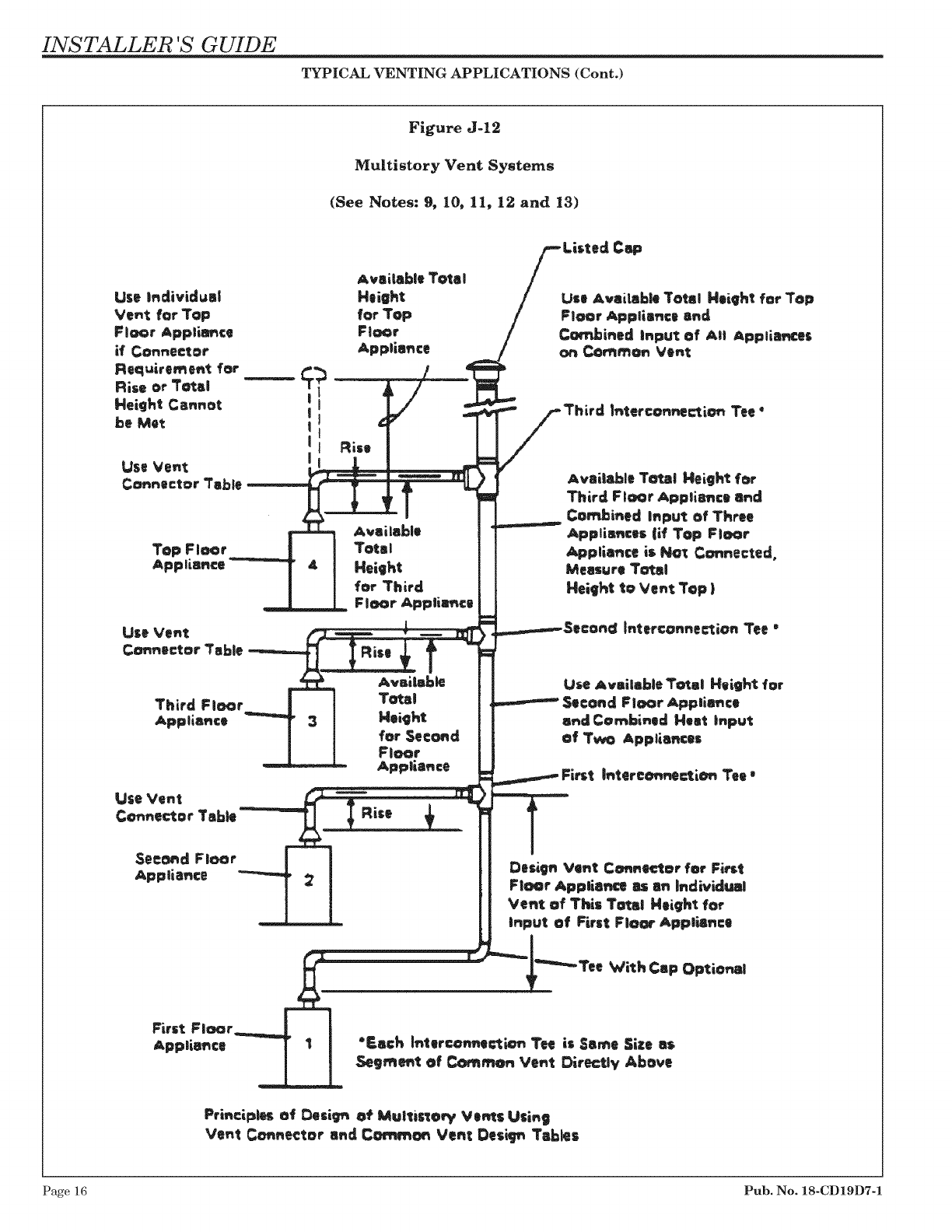
F;gure J-12
Multistory Vent Systems
(See Notes: 9, 10, 11, 12 and 13)
Cop
Pri_€_p|es of Desi_r_ _ Multis_@_f Ve_s U$i_9
Ve_t Co..e©tor a_d C_mm_ Ve_ Des_p_ Tables
Page 16 Pub. No. 18-CD19D7-1
INSTALLER 'S GUIDE
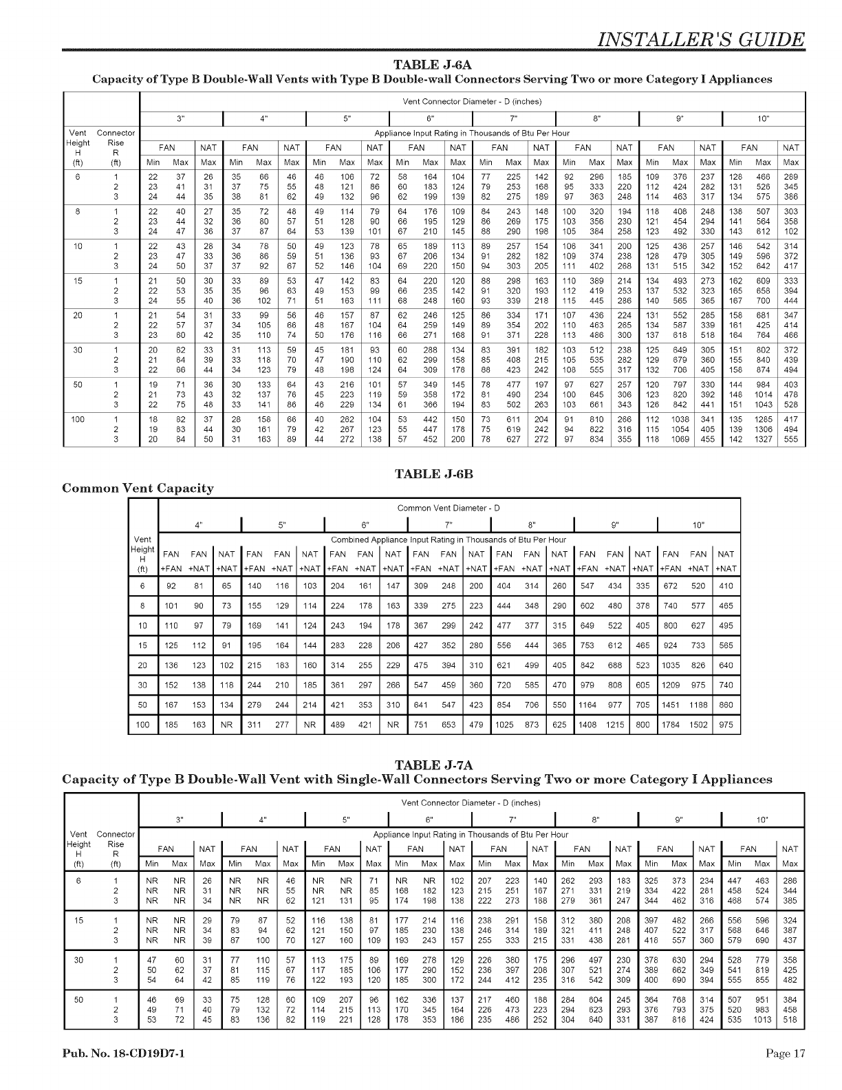
TABLE J-6A
Capacity of Type B Double-Wall Vents with Type B Double-wall Connectors Serving Two or more Category IAppliances
Vent Connector Diameter - D (inches)
8,, I 4,, I 5,, I 6,, I 7,, I 8,, I 9,, I 10,,
Vent Connector Appliance Input Rating in Thousands of Btu Per Hour
Height Rise FAN NAT FAN NAT FAN NAT FAN NAT FAN NAT FAN NAT FAN NAT FAN NAT
H R
(fl) (fi) Min Max Max Min Max Max Min Max Max Min Max Max Min Max Max Min Max Max Min Max Max Min Max Max
6 I 22 37 26 35 66 46 46 106 72 58 164 104 77 225 142 92 296 185 109 376 237 128 466 289
2 23 41 31 37 75 55 48 121 86 60 183 124 79 253 168 95 333 220 112 424 282 131 526 345
3 24 44 35 38 81 62 49 132 96 62 199 139 82 275 189 97 363 248 114 463 317 134 575 386
8 I 22 40 27 35 72 48 49 114 79 64 176 109 84 243 148 100 320 194 118 408 248 138 507 303
2 23 44 32 36 80 57 51 128 90 66 195 129 86 269 175 103 356 230 121 454 294 141 564 358
3 24 47 36 37 87 64 53 139 101 67 210 145 88 290 198 105 384 258 123 492 330 143 612 102
10 I 22 43 28 34 78 50 49 123 78 65 189 113 89 257 154 106 341 200 125 436 257 146 542 314
2 23 47 33 36 86 59 51 136 93 67 206 134 91 282 182 109 374 238 128 479 305 149 596 372
3 24 50 37 37 92 67 52 146 104 69 220 150 94 303 205 111 402 268 131 515 342 152 642 417
15 I 21 50 30 33 89 53 47 142 83 64 220 120 88 298 163 110 389 214 134 493 273 162 609 333
2 22 53 35 35 96 63 49 153 99 66 235 142 91 320 193 112 419 253 137 532 323 165 658 394
3 24 55 40 36 102 71 51 163 111 68 248 160 93 339 218 115 445 286 140 565 365 167 700 444
20 I 21 54 31 33 99 56 46 157 87 62 246 125 86 334 171 107 436 224 131 552 285 158 681 347
2 22 57 37 34 105 66 48 167 104 64 259 149 89 354 202 110 463 265 134 587 339 161 425 414
3 23 60 42 35 110 74 50 176 116 66 271 168 91 371 228 113 486 300 137 618 518 164 764 466
30 I 20 62 33 31 113 59 45 181 93 60 288 134 83 391 182 103 512 238 125 649 305 151 802 372
2 21 64 39 33 118 70 47 190 110 62 299 158 85 408 215 105 535 282 129 679 360 155 840 439
3 22 66 44 34 123 79 48 198 124 64 309 178 88 423 242 108 555 317 132 706 405 158 874 494
50 I 19 71 36 30 133 64 43 216 101 57 349 145 78 477 197 97 627 257 120 797 330 144 984 403
2 21 73 43 32 137 76 45 223 119 59 358 172 81 490 234 100 645 306 123 820 392 148 1014 478
3 22 75 48 33 141 86 46 229 134 61 366 194 83 502 263 103 661 343 126 842 441 151 1043 528
100 I 18 82 37 28 158 66 40 262 104 53 442 150 73 611 204 91 810 266 112 1038 341 135 1285 417
2 19 83 44 30 161 79 42 267 123 55 447 178 75 619 242 94 822 316 115 1054 405 139 1306 494
3 20 84 50 31 163 89 44 272 138 57 452 200 78 627 272 97 834 355 118 1069 455 142 1327 555
TABLE J-6B
Common Vent Capacity
Common Vent Diameter - D
I 5,, I 0 I 7,, I 8,, I 9,, I 10,,
4"
Vent
Height FAN FAN NAT I FAN FAN
HI
(ft) +FAN +NAT +NATI+FAN +NAT
6 92 81 65 140 116
8 101 90 73 155 129
10 110 97 79 169 141
15 125 112 91 195 164
20 136 123 102 215 183
30 152 138 118 244 210
50 167 153 134 279 244
100 185 163 NR 311 277
Combined Appliancetnput Ratingin Thousands of Btu Per Hour
NAT FAN FAN NATIFAN FAN NATIFAN FAN NATIFAN FAN NAT
+NAT +FAN +NAT +NAT +FAN +NAT +NAT +FAN +NAT +NAT +FAN +NAT +NAT
103 204 161 147 309 248 200 404 314 260 547 434 335
114 224 178 163 339 275 223 444 348 290 602 480 378
124 243 194 178 367 299 242 477 377 315 649 522 405
144 283 228 206 427 352 280 556 444 365 753 612 465
160 314 255 229 475 394 310 621 499 405 842 688 523
185 361 297 266 547 459 360 720 585 470 979 808 605
214 421 353 310 641 547 423 854 706 550 1164 977 705
NR 489 421 NR 751 653 479 1025 873 625 1408 1215 800
FAN FAN
+FAN +NAT
672 520
740 577
800 627
924 733
1035 826
1209 975
1451 1188
1784 1502
NAT
+NAT
410
465
495
565
64O
74O
86O
975
TABLE J-7A
Capacity of Type B Double-Wal! Vent with Single-Wal! Connectors Serving Two or more Category IAppliances
Vent Conne_or Diameter - D (inches)
3,, I 4,, I 5,, I 6,, I 7,, I 8,, I 9,, I 10,,
Vent Connector Appliance Input Rating in Thousands of Btu Per Hour
Height Rise FA. .AT FA. .AT FA. .AT .AT .AT .AT FA. .AT FA. .AT
nnnn
H R IIII
(fi) (fl) Min Max Max Min Max Max Min Max Max Min Max Max Min Max Max Min Max Max Min Max Max Min Max Max
6 1 NR NR 26 NR NR 46 NR NR 71 NR NR 102 207 223 140 262 293 183 325 373 234 447 463 286
2 NR NR 31 NR NR 55 NR NR 85 168 182 123 215 251 167 271 331 219 334 422 281 458 524 344
3 NR NR 34 NR NR 62 121 131 95 174 198 138 222 273 188 279 361 247 344 462 316 468 574 385
15 1 NR NR 29 79 87 52 116 138 81 177 214 116 238 291 158 312 380 208 397 482 266 556 596 324
2 NR NR 34 83 94 62 121 150 97 185 230 138 246 314 189 321 411 248 407 522 317 568 646 387
3 NR NR 39 87 100 70 127 160 109 193 243 157 255 333 215 331 438 281 418 557 360 579 690 437
30 1 47 60 31 77 110 57 113 175 89 169 278 129 226 380 175 296 497 230 378 630 294 528 779 358
2 50 62 37 81 115 67 117 185 106 177 290 152 236 397 208 307 521 274 389 662 349 541 819 425
3 54 64 42 85 119 76 122 193 120 185 300 172 244 412 235 316 542 309 400 690 394 555 855 482
50 1 46 69 33 75 128 60 109 207 96 162 336 137 217 460 188 284 604 245 364 768 314 507 951 384
2 49 71 40 79 132 72 114 215 113 170 345 164 226 473 223 294 623 293 376 793 375 520 983 458
3 53 72 45 83 136 82 119 221 128 178 353 186 235 486 252 304 640 331 387 816 424 535 1013 518
Pub. No. 18-CD19D7-1 Page 17
INSTALLER 'S GUIDE
Common Vent Capacity
4"
Vent
HeightH FAN FAN NAT
(if) +FAN +NAT +NAT
6 89 78 64
8 98 87 71
10 106 94 76
15 121 108 88
20 131 118 98
30 145 132 113
50 159 145 128
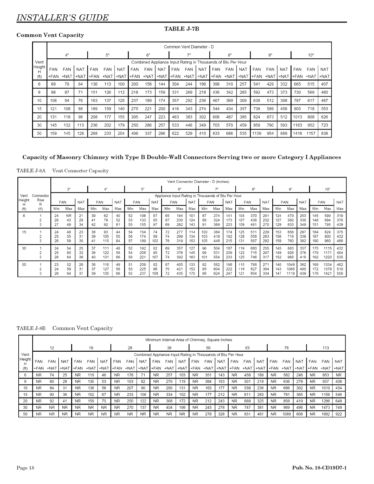
TABLE J-7B
FAN FAN
+FAN +NAT
136 113
151 126
163 137
189 159
208 177
236 202
268 233
I 6"
Combined ApptiancelnputRatinginThousandsofBtu PerHour
NAT FAN FAN NAT FAN FAN NAT FAN FAN NAT
+NAT +FAN +NAT +NAT +FAN +NAT +NAT +FAN +NAT +NAT
200 158
218 173
237 189
275 221
305 247
250 286
406 337
144
159
174
200
223
257
296
Common Vent Diameter- D
I 7,, 8,, I 9,,
FAN FAN NAT
+FAN +NAT +NAT
304 244 196 398 310 257 541 429 332
331 269 218 436 342 285 592 473 373
357 292 236 467 369 309 638 512 398
416 343 274 544 434 357 738 599 456
463 383 302 606 487 395 824 673 512
533 446 349 703 570 459 958 790 593
622 529 410 833 686 535 1139 954 689
lOO
112
12o
14o
155
179
204
1 O"
FAN FAN NAT
+FAN +NAT +NAT
665 515 407
730 569 460
787 617 487
905 718 553
1013 808 626
1183 952 723
1418 1157 838
Capacity of Masonry Chimney with Type B Double-Wal! Connectors Serving two or more Category IAppliances
TABLE J-SA Vent Connector Capacity
Vent Connector Diameter - D (inches)
3,, I 4,, I 5,, I 8,, I 7,, I 8,, I 9,, I 10,,
Vent Conne_or Appliance Input Rating in Thousands of Btu Per Hour
Height Rise FAN INAT FAN NATI FAN INAT FAN NATI FAN INAT FAN NATI FAN INAT FAN NAT
H R
(fl) (fl) Min Max Max Min Max Max Min Max Max Min Max Max Min Max Max Min Max Max Min Max Max Min Max Max
6 I 24 NR 21 39 62 40 52 106 67 65 194 101 87 274 141 104 370 201 124 479 253 145 599 319
2 26 43 28 41 79 52 53 133 85 67 230 124 89 324 173 107 436 232 127 562 330 148 694 378
3 27 49 34 42 92 61 55 155 97 69 262 143 91 369 203 109 491 270 129 633 349 151 795 439
15 I 24 48 23 38 93 44 54 154 74 72 277 114 100 384 174 125 511 229 153 658 297 184 824 375
2 25 55 31 39 105 55 56 174 89 74 299 134 103 419 192 128 558 263 156 718 339 187 900 432
3 26 59 35 41 115 64 57 189 102 76 319 153 105 448 215 131 597 292 159 760 382 190 960 486
30 I 24 54 25 37 111 48 52 192 82 69 357 127 96 504 187 119 680 255 145 883 337 175 1115 432
2 25 60 32 38 122 58 54 208 95 72 376 145 99 531 209 122 715 287 149 928 378 179 1171 484
3 26 64 36 40 131 66 56 221 107 74 392 163 101 554 233 125 746 317 152 968 418 182 1220 535
50 I 23 52 26 36 116 49 51 209 82 67 405 133 92 582 198 115 798 271 140 1049 362 168 1334 462
2 24 59 31 37 127 58 53 225 96 70 421 152 95 604 222 118 827 304 143 1085 400 172 1379 510
3 26 64 37 39 135 66 55 237 108 72 435 170 98 624 247 121 854 334 147 1118 439 176 1421 558
TABLE J-SB Common Vent Capacity
12
Vent
Height FAN FAN
H
(ft) +FAN +NAT
6 NR 74
8 NR 80
10 NR 84
15 NR 90
20 NR 92
30 NR NR
50 NR NR
NAT
+NAT
25
28
31
36
41
NR
NR
Minimum Internal Area of Chimney, Square Inches
19 28 38 I 50 63 78
I
FAN FAN NAT FAN FAN
+FAN +NAT +NAT +FAN +NAT
NR 119 46 NR 178
NR 130 53 NR 193
NR 138 56 NR 207
NR 152 67 NR 233
NR 159 75 NR 250
NR NR NR NR 270
NR NR NR NR NR
Combined Apptiancelnput Ratingin Thousands of Btu Per Hour
NAT FAN FAN NAT FAN FAN NAT
+NAT +FAN +NAT +NAT +FAN +NAT +NAT
71 NR 257 103 NR 351 143
82 NR 279 119 NR 384 163
90 NR 299 131 NR 163 177
106 NR 334 152 NR 177 212
122 NR 368 172 NR 212 243
137 NR 404 198 NR 243 278
NR NR NR NR NR 278 328
FAN FAN NAT FAN FAN
+FAN +NAT +NAT +FAN +NAT
NR 458 188 NR 582
NR 501 218 NR 636
NR 538 236 NR 686
NR 611 283 NR 781
NR 668 325 NR 858
NR 747 381 NR 969
NR 831 461 NR 1089
NAT
+NAT
246
278
302
365
419
496
606
NR 853
NR 937
NR 1010
NR 1156
NR 1286
NR 1473
NR 1692
I 113
FAN FAN NAT
+FAN +NAT +NAT
NR
4O8
454
546
648
749
922
Page 18 Pub. No. 18-CD19D7-1
INSTALLER 'S GUIDE
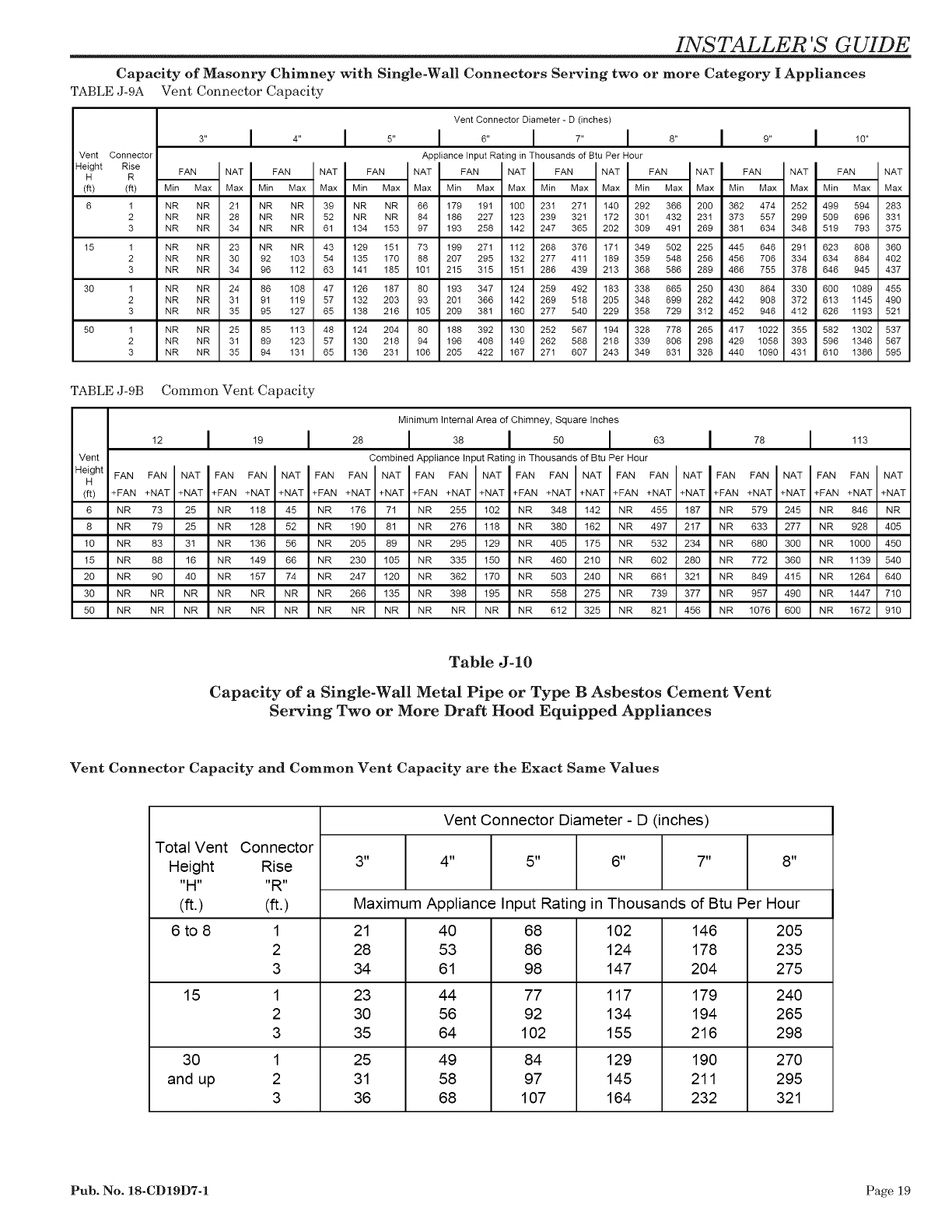
Capacity of Masonry Chimney with Single-Wal! Connectors Serving two or more Category I Appliances
TABLE J-9A Vent Connector Capacity
Vent Connector
Height Rise
H R
(ft) (ft)
6 1
2
3
15 1
2
3
30 1
2
3
50 1
2
3
Vent Connector Diameter - D (inches)
3 I 4 I 5 I 6 I 7 I 8 I 9 I 10
Appliance Input Rating in Thousands of Btu Per Hour
mmmn
FA. "ATI FA. .AT FA. "ATI .AT "ATI .AT FA. "ATI FA. .AT
Min Max Max Min Max Max Min Max Max Min Max Max Min Max Max Min Max Max Min Max Max Min Max Max
NR NR
NR NR
NR NR
NR NR
NR NR
NR NR
NR NR
NR NR
NR NR
NR NR
NR NR
NR NR
21
28
34
23
30
34
24
31
35
25
31
35
NR NR
NR NR
NR NR
NR NR
92 103
96 112
86 108
91 119
95 127
85 113
89 123
94 131
39 NR NR
52 NR NR
61 134 153
43 129 151
54 135 170
63 141 185
47 126 187
57 132 203
65 138 216
48 124 204
57 130 218
65 136 231
66 179 191
84 186 227
97 193 258
73 199 271
88 207 295
101 215 315
80 193 347
93 201 366
105 209 381
80 188 392
94 196 408
106 205 422
100 231 271
123 239 321
142 247 365
112 268 376
132 277 411
151 286 439
124 259 492
142 269 518
160 277 540
130 252 567
149 262 588
167 271 607
140 292 366
172 301 432
202 309 491
171 349 502
189 359 548
213 368 586
183 338 665
205 348 699
229 358 729
194 328 778
218 339 806
243 349 831
200 362 474
231 373 557
269 381 634
225 445 646
256 456 706
289 466 755
250 430 864
282 442 908
312 452 946
265 417 1022
298 429 1058
328 440 1090
252
299
348
291
334
378
330
372
412
355
393
431
499 594
509 696
519 793
623 808
634 884
646 945
600 1089
613 1145
626 1193
582 1302
596 1346
610 1386
283
331
375
360
402
437
455
49O
521
537
567
595
TABLE J-9B Common Vent Capacity
12
Vent
Height FAN FAN
H
(ft) +FAN +NAT
6 NR 73
8 NR 79
10 NR 83
15 NR 88
20 NR 90
30 NR NR
50 NR NR
NAT
+NAT
25
25
31
16
4O
NR
NR
19
FAN FAN NAT
+FAN +NAT +NAT
NR 118 45
NR 128 52
NR 136 56
NR 149 66
NR 157 74
NR NR NR
NR NR NR
28
FAN FAN
+FAN +NAT
NR 176
NR 190
NR 205
NR 230
NR 247
NR 266
NR NR
Minimum Internal Area of Chimney, Square Inches
I 36 I
Combined Appliance Input Rating in Thousands of Btu Per Hour
NAT FAN FAN NAT FAN FAN NAT
+NAT +FAN +NAT +NAT +FAN +NAT +NAT
71 NR 255 102 NR 348 142
81 NR 276 118 NR 380 162
89 NR 295 129 NR 405 175
105 NR 335 150 NR 460 210
120 NR 362 170 NR 503 240
135 NR 398 195 NR 558 275
NR NR NR NR NR 612 325
63 78
FAN FAN NAT FAN FAN
+FAN +NAT +NAT +FAN +NAT
NR 455 187 NR 579
NR 497 217 NR 633
NR 532 234 NR 680
NR 602 280 NR 772
NR 661 321 NR 849
NR 739 377 NR 957
NR 821 456 NR 1076
NAT
+NAT
245
277
300
360
415
490
600
I 113
FAN FAN NAT
+FAN +NAT +NAT
NR 846 NR
NR 928 405
NR 1000 450
NR 1139 540
NR 1264 640
NR 1447 710
NR 1672 910
Table J-1O
Capacity of a Single-Wall Metal Pipe or Type B Asbestos Cement Vent
Serving Two or More Draft Hood Equipped Appliances
Vent Connector Capacity and Common Vent Capacity are the Exact Same Values
Vent Connector Diameter - D (inches)
Total Vent Connector
Height Rise 3" 4" 5" 6" 7" 8"
"H.... R"
(ft.) (ft.) Maximum Appliance Input Rating in Thousands of Btu Per Hour
6 to 8 1 21 40 68 102 146 205
2 28 53 86 124 178 235
3 34 61 98 147 204 275
15 1 23 44 77 117 179 240
2 30 56 92 134 194 265
3 35 64 102 155 216 298
30
and up
1
2
3
25
31
36
49
58
68
84
97
107
129
145
164
190
211
232
270
295
321
Pub. No. 18-CD19D7-1 Page 19
INSTALLER 'S GUIDE
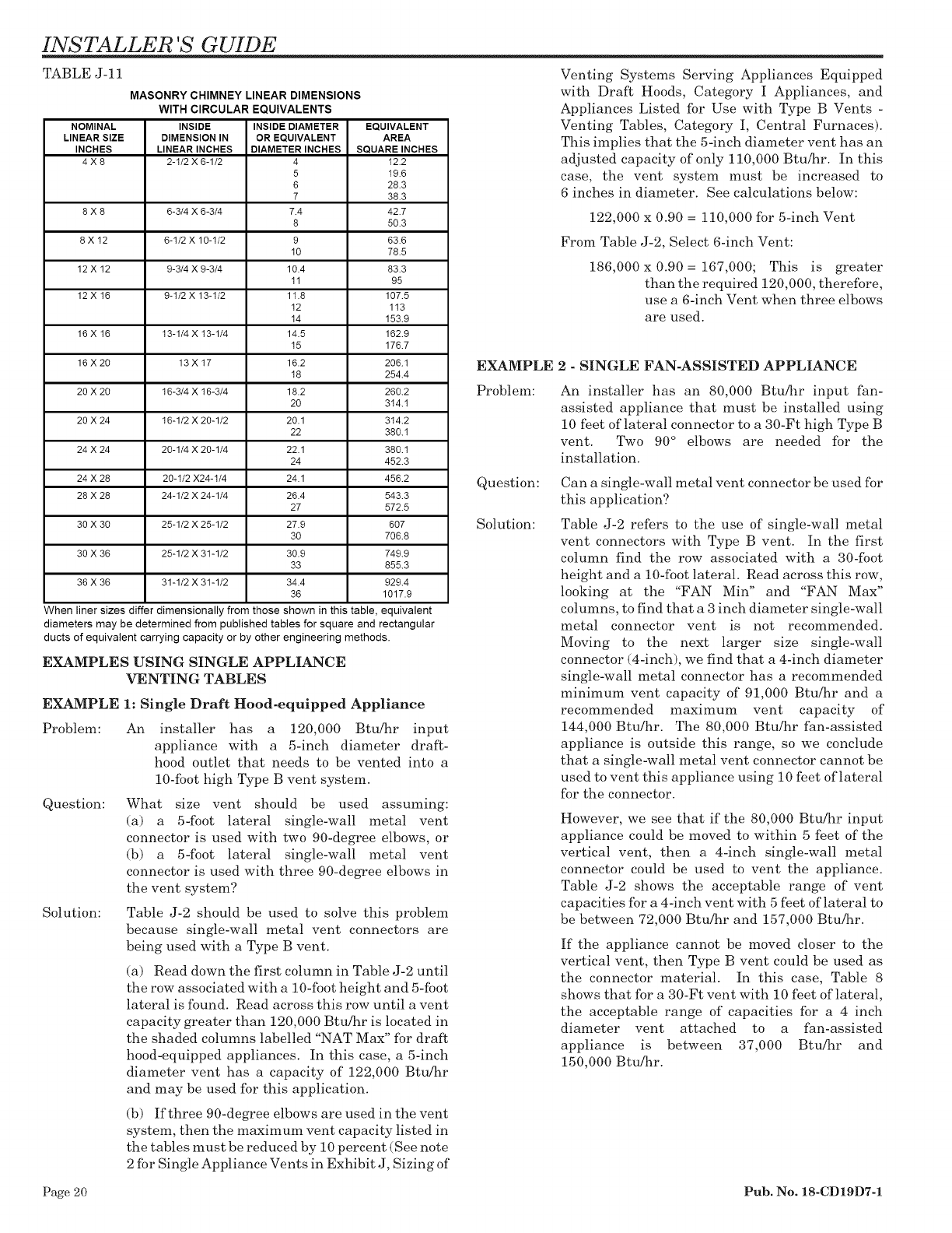
TABLE J-11
MASONRY CHIMNEY LINEAR DIMENSIONS
WITH CIRCULAR EQUIVALENTS
NOMINAL INSIDE INSIDE DIAMETER EQUIVALENT
LINEAR SIZE DIMENSION IN OR EQUIVALENT AREA
INCHES LINEAR INCHES DIAMETER INCHES SQUARE INCHES
4 X 8 2-1/2 X 6-1/2 4 122
5 19.6
6 28.3
7 38.3
8 X 8 6-3/4 X 6-3/4 7.4 42.7
8 50.3
8 X 12 6-1/2 X 10-1/2 9 63.6
10 78.5
12 X 12 9-3/4 X 9-3/4 10.4 83.3
11 95
12 X 16 9-1/2 X 13-1/2 11.8 107.5
12 113
14 153.9
16 X 16 13-1/4 X 13-1/4 14.5 162.9
15 176.7
16 X 20 13 X 17 16.2 206.1
18 254.4
20 X 20 16-3/4 X 16-3/4 18.2 260.2
20 314.1
20 X 24 16-1/2 X 20-1/2 20.1 3142
22 380.1
24 X 24 20-1/4 X 20-1/4 22.1 380.1
24 452.3
24 X 28 20-1/2 X24-1/4 24.1 4562
28 X 28 24-1/2 X 24-1/4 26.4 543.3
27 572.5
30 X 30 25-1/2 X 25-1/2 27.9 607
30 706.8
30 X 36 25-1/2 X 31-1/2 30.9 749.9
33 855.3
36 X 36 31-1/2 X 31-1/2 34.4 929.4
36 1017.9
When liner sizes differ dimensionally from those shown in this table, equivalent
diameters may be determined from published tables for square and rectangular
ducts of equivalent carrying capacity or by other engineering methods.
EXAMPLES USING SINGLE APPLIANCE
VENTING TABLES
EXAMPLE 1: Single Draft Hood-equipped Appliance
Problem: An installer has a 120,000 Btu/hr input
appliance with a 5-inch diameter draft-
hood outlet that needs to be vented into a
10-foot high Type B vent system.
Question: What size vent should be used assuming:
(a) a 5-foot lateral single-wall metal vent
connector is used with two 90-degree elbows, or
(b) a 5-foot lateral single-wall metal vent
connector is used with three 90-degree elbows in
the vent system?
Solution: Table J-2 should be used to solve this problem
because single-wall metal vent connectors are
being used with a Type B vent.
(a) Read down the first column in Table J-2 until
the row associated with a 10-foot height and 5-foot
lateral is found. Read across this row until a vent
capacity greater than 120,000 Btufar is located in
the shaded columns labelled "NAT Max" for draft
hood-equipped appliances. In this case, a 5-inch
diameter vent has a capacity of 122,000 Btufar
and may be used for this application.
(b) If three 90-degree elbows are used in the vent
system, then the maximum vent capacity listed in
the tables must be reduced by 10 percent (See note
2 for Single Appliance Vents in Exhibit J, Sizing of
EXAMPLE
Problem:
Question:
Solution:
Venting Systems Serving Appliances Equipped
with Draft Hoods, Category I Appliances, and
Appliances Listed for Use with Type B Vents -
Venting Tables, Category I, Central Furnaces).
This implies that the 5-inch diameter vent has an
adjusted capacity of only 110,000 Btu/hr. In this
case, the vent system must be increased to
6 inches in diameter. See calculations below:
122,000 x 0.90 = 110,000 for 5-inch Vent
From Table J-2, Select 6-inch Vent:
186,000 x 0.90 = 167,000; This is greater
than the required 120,000, therefore,
use a 6-inch Vent when three elbows
are used.
2 - SINGLE FAN-ASSISTED APPLIANCE
An installer has an 80,000 Btu/hr input fan-
assisted appliance that must be installed using
10 feet of lateral connector to a 30-Ft high Type B
vent. Two 90 ° elbows are needed for the
installation.
Can a single-wall metal vent connector be used for
this application?
Table J-2 refers to the use of single-wall metal
vent connectors with Type B vent. In the first
column find the row associated with a 30-foot
height and a 10-foot lateral. Read across this row,
looking at the "FAN Min" and "FAN Max"
columns, to find that a 3 inch diameter single-wall
metal connector vent is not recommended.
Moving to the next larger size single-wall
connector (4-inch), we find that a 4-inch diameter
single-wall metal connector has a recommended
minimum vent capacity of 91,000 Btu/hr and a
recommended maximum vent capacity of
144,000 Btu/hr. The 80,000 Btu/hr fan-assisted
appliance is outside this range, so we conclude
that a single-wall metal vent connector cannot be
used to vent this appliance using 10 feet of lateral
for the connector.
However, we see that if the 80,000 Btu/hr input
appliance could be moved to within 5 feet of the
vertical vent, then a 4-inch single-wall metal
connector could be used to vent the appliance.
Table J-2 shows the acceptable range of vent
capacities for a 4-inch vent with 5 feet of lateral to
be between 72,000 Btu/hr and 157,000 Btu/hr.
If the appliance cannot be moved closer to the
vertical vent, then Type B vent could be used as
the connector material. In this case, Table 8
shows that for a 30-Ft vent with 10 feet of lateral,
the acceptable range of capacities for a 4 inch
diameter vent attached to a fan-assisted
appliance is between 37,000 Btu/hr and
150,000 Btu/hr.
Page 20 Pub. No. 18-CD19D7-1
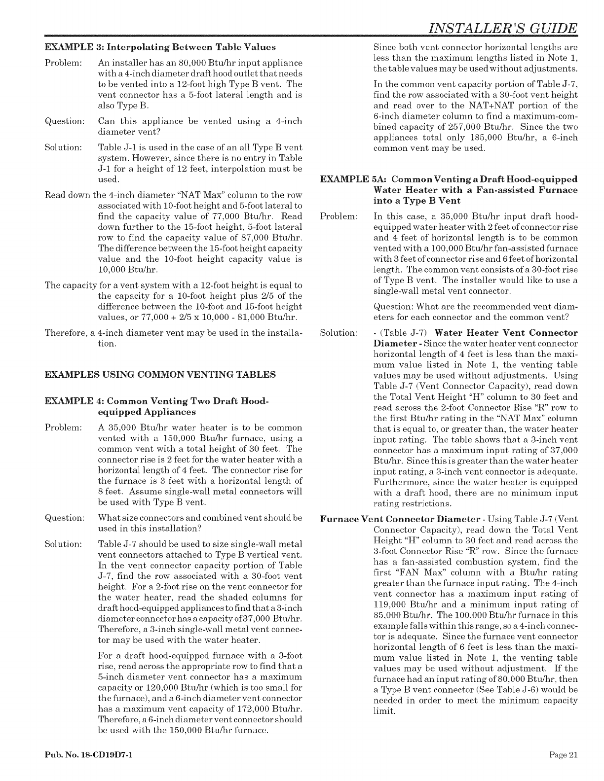
EXAMPLE
Problem:
Question:
3: Interpolating Between Table Values
An installer has an 80,000 Btu/hr input appliance
with a 4-inch diameter draft hood outlet that needs
to be vented into a 12-foot high Type B vent. The
vent connector has a 5-foot lateral length and is
also Type B.
Can this appliance be vented using a 4-inch
diameter vent?
Solution: Table J-1 is used in the case of an all Type B vent
system. However, since there is no entry in Table
J-1 for a height of 12 feet, interpolation must be
used.
Read down the 4-inch diameter "NAT Max" column to the row
associated with 10-foot height and 5-foot lateral to
find the capacity value of 77,000 Btu/hr. Read
down further to the 15-foot height, 5-foot lateral
row to find the capacity value of 87,000 Btu/hr.
The difference between the 15-foot height capacity
value and the 10-foot height capacity value is
10,000 Btu/hr.
The capacity for a vent system with a 12-foot height is equal to
the capacity for a 10-foot height plus 2/5 of the
dif%rence between the 10-foot and 15-foot height
values, or 77,000 + 2/5 x 10,000 - 81,000 Btu/hr.
Therefore, a 4-inch diameter vent may be used in the installa-
tion.
EXAMPLES USING COMMON VENTING TABLES
EXAMPLE
Problem:
Question:
Solution:
4: Common Venting Two Draft Hood-
equipped Appliances
A 35,000 Btu/hr water heater is to be common
vented with a 150,000 Btu/hr furnace, using a
common vent with a total height of 30 feet. The
connector rise is 2 feet for the water heater with a
horizontal length of 4 feet. The connector rise for
the furnace is 3 feet with a horizontal length of
8 feet. Assume single-wall metal connectors will
be used with Type B vent.
What size connectors and combined vent should be
used in this installation?
Table J-7 should be used to size single-wall metal
vent connectors attached to Type B vertical vent.
In the vent connector capacity portion of Table
J-7, find the row associated with a 30-foot vent
height. For a 2-foot rise on the vent connector for
the water heater, read the shaded columns for
draft hood-equipped appliances to find that a 3-inch
diameter connector has a capacity of 37,000 Btu/hr.
Therefore, a 3-inch single-wall metal vent connec-
tor may be used with the water heater.
For a draft hood-equipped furnace with a 3-foot
rise, read across the appropriate row to find that a
5-inch diameter vent connector has a maximum
capacity or 120,000 Btu/hr (-which is too small for
the furnace), and a 6-inch diameter vent connector
has a maximum vent capacity of 172,000 Btu/hr.
Therefore, a 6-inch diameter vent connector should
be used with the 150,000 Btu/hr furnace.
INSTALLER 'S GUIDE
Since both vent connector horizontal lengths are
less than the maximum lengths listed in Note 1,
the table values may be used -without adjustments.
In the common vent capacity portion of Table J-7,
find the row associated with a 30-foot vent height
and read over to the NAT+NAT portion of the
6-inch diameter eolumn to find a maximum-com-
bined capacity of 257,000 Btu/hr. Since the two
appliances total only 185,000 Btu/hr, a 6-inch
common vent may be used.
EXAMPLE
Problem:
5A: CommonVenting a Draft Hood-equipped
Water Heater with a Fan-assisted Furnace
into a Type B Vent
In this case, a 35,000 Btu/hr input draft hood-
equipped water heater with 2 feet of connector rise
and 4 feet of horizontal length is to be common
vented -with a 100,000 Btu/hr fan-assisted furnace
with 3 feet of connector rise and 6 feet of horizontal
length. The common vent consists of a 30-foot rise
of Type B vent. The installer would like to use a
single-wall metal vent connector.
Question: What are the recommended vent diam-
eters for each connector and the common vent?
Solution: -(Table J-7) Water Heater Vent Connector
Diameter - Since the water heater vent connector
horizontal length of 4 feet is less than the maxi-
mum value listed in Note 1, the venting table
values may be used without adjustments. Using
Table J-7 (Vent Connector Capacity), read down
the Total Vent Height "H" column to 30 feet and
read across the 2-foot Connector Rise "R" row to
the first Btu/hr rating in the "NAT Max" column
that is equal to, or greater than, the water heater
input rating. The table shows that a 3-inch vent
connector has a maximum input rating of 37,000
Btu/hr. Since this is greater than the water heater
input rating, a 3-inch vent connector is adequate.
Furthermore, since the water heater is equipped
with a draft hood, there are no minimum input
rating restrictions.
Furnace Vent Connector Diameter - Using Table J-7 (Vent
Connector Capacity), read down the Total Vent
Height "H" column to 30 feet and read across the
3-foot Connector Rise "R" row. Since the furnace
has a fan-assisted combustion system, find the
first "FAN Max" column with a Btu/hr rating
greater than the furnace input rating. The 4-inch
vent connector has a maximum input rating of
119,000 Btu/hr and a minimum input rating of
85,000 Btu/hr. The 100,000 Btu/hr furnace in this
example falls within this range, so a 4-inch connec-
tor is adequate. Since the furnace vent connector
horizontal length of 6 feet is less than the maxi-
mum value listed in Note 1, the venting table
values may be used without adjustment. If the
furnace had an input rating of 80,000 Btu/hr, then
a Type B vent connector (See Table J-6) would be
needed in order to meet the minimum capacity
limit.
Pub. No. 18-CD19D7-1 Page 21
INSTALLER 'S GUIDE
Common Vent Diameter - The total input to the com-
mon vent is 135,000 Btu/hr. Using Table J-7, (Com-
mon Vent Capacity) read down the Total Vent Height
"H" column to 30 feet and across this row to find the
smallest vent diameter in the "FAN+NAT" column
that has a Btu/hr rating equal to, or greater than
135,000 Btu/hr. The 4-inch common vent has a capac-
ity of 132,000 Btu/hr and the 5-inch common vent has
a capacity of 202,000 Btu/hr. Therefore, the 5-inch
common vent should be used in this Example.
Summary - In this Example, the installer may use a
3-inch diameter, single-wall metal vent connector for
the water heater and a 4-inch diameter, single-wall
metal vent connector for the furnace. The common
vent should be a 5-inch diameter Type B vent.
mum input rating of 127,000 Btu/hr and a minimum
input rating of 95,000 Btu/hr. The 100,000 Btu/hr
furnace in this example falls within this range, so a
4-inch connector is adequate.
Masonry Chimney. From Table J-11, the Equivalent
Area for a Nominal Liner size of 8 inches X 12 inches
is 63.6 square inches. Using Table J-9 (Common Vent
Capacity), read down the "Fan+Nat" column under the
Minimum Internal Area of Chimney value of 63, to the
row for 30 foot height, to find a capacity value of
739,000 Btu/hr. The combined input rating of the
furnace and water heater, 135,000 Btu/hr, is less than
the table value, so this is an acceptable installation.
EXAMPLE 5B - Common Venting Into a Masonry
Chimney
Problem:
Question:
In this case, a 35,000 Btu/hr input draft
hood-equipped water heater with 2 feet of
connector rise and 4 feet of horizontal length
is to be common vented with a i00,000 Btu/hr
fan-assisted furnace with 3 feet of connector
rise and 6 feet of horizontal length. The
common vent is a clay tile lined masonry
chimney with a 30 foot height. The internal
dimensions of the clay tile liner are nomi-
nally 8 inches X 12 inches.
Assuming the same vent connector heights,
laterals, and materials found in Example 5A,
what are the recommended vent connector
diameters and is this an acceptable installa-
tion?
Solution: Table J-9 is used to size common venting
installations involving single wall connec-
tors into masonry chimneys.
Water Heater Vent Connector Diameter. Using
Table J-9 (Vent Connector Capacity), read down the
Total Vent Height "H" column to 30 feet and read
across the 2-foot Connector Rise "R" row to the first
Btu/hr rating in the "NAT Max" column that is equal
to or greater than the water heater input rating. The
table shows that a 3 inch vent connector has a maxi-
mum input of only 31,000 Btu/hr, while a 4-inch vent
connector has a maximum input of 57,000 Btu/hr. A
4-inch vent connector must therefore be used.
Furnace Vent Connector Diameter. Using Table J-9
(Vent Connector Capacity), read down the Total Vent
Height "H" column to 30 feet and across the 3-foot
Connector Rise "R" row. Since the furnace has a fan-
assisted combustion system, find the first "FAN Max"
column with a Btu/hr rating greater than the furnace
input rating. The 4-inch vent connector has a maxi-
Page 22 Pub. No. 18-CD19D7-1
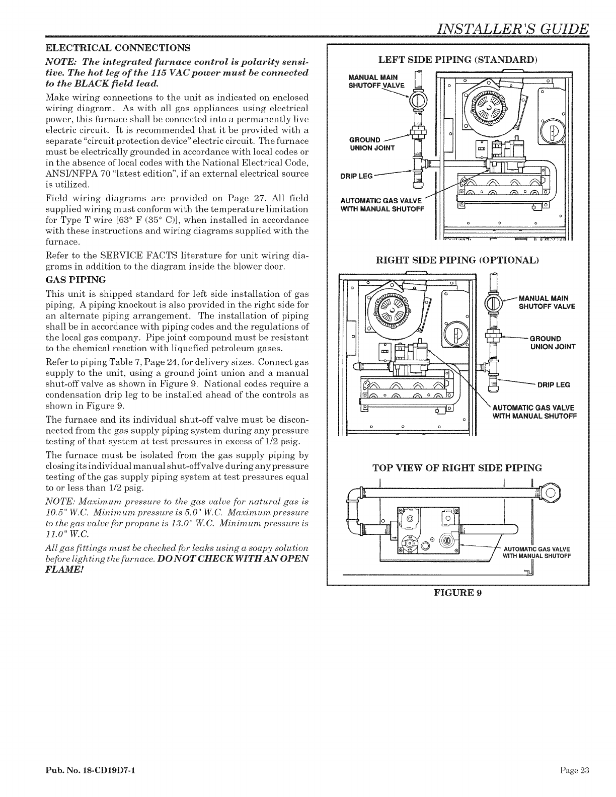
ELECTRICAL CONNECTIONS
NOTE: The integrated furnace control is polarity sensi-
tive. The hot leg of the 115 VAC power must be connected
to the BLACK field lead.
Make wiring connections to the unit as indicated on enclosed
wiring diagram. As with all gas appliances using electrical
power, this furnace shall be connected into a permanently live
electric circuit. It is recommended that it be provided with a
separate "circuit protection device" electric circuit. The furnace
must be electrically grounded in accordance with local codes or
in the absence of local codes with the National Electrical Code,
ANSI/NFPA 70 "latest edition", if an external electrical source
is utilized.
Field -wiring diagrams are provided on Page 27. All field
supplied wiring must conform with the temperature limitation
for Type T wire [63 ° F (35 ° C)], -when installed in accordance
with these instructions and wiring diagrams supplied with the
furnace.
Refer to the SERVICE FACTS literature for unit wiring dia-
grams in addition to the diagram inside the blower door.
GAS PIPING
This unit is shipped standard for left side installation of gas
piping, A piping knockout is also provided in the right side for
an alternate piping arrangement. The installation of piping
shall be in accordance with piping codes and the regulations of
the local gas company. Pipe joint compound must be resistant
to the chemical reaction with liquefied petroleum gases.
Refer to piping Table 7, Page 24, for delivery sizes. Connect gas
supply to the unit, using a ground joint union and a manual
shut-off valve as shown in Figure 9. National codes require a
condensation drip leg to be installed ahead of the controls as
shown in Figure 9.
The furnace and its individual shut-off valve must be discon-
nected from the gas supply piping system during any pressure
testing of that system at test pressures in excess of 1/2 psig.
The furnace must be isolated from the gas supply piping by
closing its individual manual shut-offvalve during any pressure
testing of the gas supply piping system at test pressures equal
to or less than 1/2 psig.
NOTE: Maximum pressure to the gas valve for natural gas is
10.5" W.C. Minimum pressure is 5.0" W.C. Maximum pressure
to the gas valve for propane is 13.0" W.C. Minim urn pressure is
11.0" W.C.
All gas fittings m ust be checked fi)r leaks using a soapy solution
before ligh ring the furnace. DO NOT CHECK WITH AN OPEN
FLAME!
INSTALLER 'S GUIDE
LEFT SIDE PIPING (STANDARD)
MANUAL MAIN
SHUTOFF
GROUND
UNION JOINT
DRiP LEG
AUTOMATIC GAS VALVE
WiTH MANUAL SHUTOFF
RIGHT SIDE PIPING (OPTIONAL)
SHUTOFF VALVE
GROUND
UNION JOINT
DRiP LEG
WiTH MANUALSHUTOFF
TOP VIEW OF RIGHT SIDE PIPING
41
FIGURE 9
Pub. No. 18-CD19D7-1 Page 23
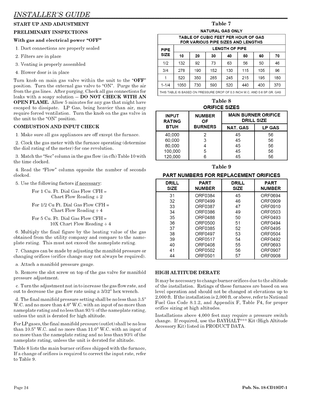
INSTALLER 'S GUIDE
START UP AND ADJUSTMENT
PRELIMINARY INSPECTIONS
With gas and electrical power "OFF"
1. Duct connections are properly sealed
2. Filters are in place
3. Venting is properly assembled
4. Blower door is in place
Turn knob on main gas valve within the unit to the "OFF"
position. Turn the external gas valve to "ON". Purge the air
from the gas lines. After purging, Check all gas connections for
leaks with a soapy solution -- DO NOT CHECK WITH AN
OPEN FLAME. Allow 5 minutes for any gas that might have
escaped to dissipate. LP Gas, being heavier than air, may
require forced ventilation. Turn the knob on the gas valve in
the unit to the "ON" position.
COMBUSTION AND INPUT CHECK
1. Make sure all gas appliances are off except the furnace.
2. Clock the gas meter with the furnace operating (determine
the dial rating of the meter) for one revolution.
3. Match the "Sec" column in the gas flow (in cfh) Table 10 with
the time clocked.
4. Read the "Flow" column opposite the number of seconds
clocked.
5. Use the following factors if necessary:
For 1 Cu. Ft. Dial Gas Flow CFH =
Chart Flow Reading + 2
For 1/2 Cu Ft. Dial Gas Flow CFH =
Chart Flow Reading + 4
For 5 Cu. Ft. Dial Gas Flow CFH =
10X Chart Flow Reading + 4
6. Multiply the final figure by the heating value of the gas
obtained from the utility company and compare to the name-
plate rating. This must not exceed the nameplate rating.
7. Changes can be made by adjusting the manifold pressure or
changing orifices (orifice change may not always be required).
a. Attach a manifold pressure gauge.
b. Remove the slot screw on top of the gas valve for manifold
pressure adjustment.
c. Turn the adjustment nut in to increase the gas flow rate, and
out to decrease the gas flow rate using a 3/32" hex wrench.
d. The final manifold pressure setting shall be no less than 3.5"
W.C. and no more than 4.0" W.C. with an input of no more than
nameplate rating and no less than 93 % of the nameplate rating,
unless the unit is derated for high altitude.
For LP gases, the final manifold pressure (outlet) shall be no less
than 10.5" W.C. and no more than 11.0" W.C. with an input of
no more than the nameplate rating and no less than 93% of the
nameplate rating, unless the unit is derated for altitude.
Table 8 lists the main burner orifices shipped -with the furnace,
Ifa change of orifices is required to correct the input rate, refer
to Table 9.
Table 7
NATURAL GAS ONLY
TABLE OF CUBIC FEET PER HOUR OF GAS
FORVARIOUS PIPE SIZES AND LENGTHS
PIPE LENGTH OF PIPE
SIZE 10 20 30 40 60 60 70
1/2 132 92 73 63 56 50 46
3/4 278 190 152 130 115 105 96
1 520 350 285 245 215 195 180
1-1/4 1050 730 590 520 440 400 370
THIS TABLE tS BASED ON PRESSURE DROP OF 0.3 INCH W.C. AND 0.6 SP.GR. GAS
INPUT
RATING
BTUH
40,000
60,000
80,000
100,000
120,000
Table 8
ORIFICE SIZES
NUMBER
OF
BURNERS
2
3
4
5
6
MAIN BURNER ORIFICE
DRILLSIZE
NAT. GAS
45
45
45
45
45
LP GAS
56
56
56
56
56
Table 9
PART NUMBERS FOR REPLACEMENT ORIFICES
DRILL
SIZE
31
32
33
34
35
36
37
38
39
40
41
44
PART
NUMBER
ORF0384
ORF0499
ORF0387
ORF0386
ORF0488
ORF0500
ORF0385
ORF0497
ORF0517
ORF0408
ORF0502
ORF0501
DRILL
SIZE
45
46
47
49
50
51
52
53
54
55
56
57
PART
NUMBER
ORF0694
ORF0909
ORF0910
ORF0503
ORF0493
ORF0494
ORF0495
ORF0504
ORF0492
ORF0693
ORF0907
ORF0908
HIGH ALTITUDE DERATE
It may be necessary to change burner orifices due to the altitude
of the installation. Ratings of these furnaces are based on sea
level operation and should not be changed at elevations up to
2,000 ft. If the installation is 2,000 ft. or above, refer to National
Fuel Gas Code 8.1.2, and Appendix F, Table F4, for proper
orifice sizing at high altitudes.
Installations above 4,000 feet may require a pressure switch
change. If required, use the BAYHALT*** Kit (High Altitude
Accessory Kit) listed in PRODUCT DATA.
Page 24 Pub. No. 18-CD19D7-1
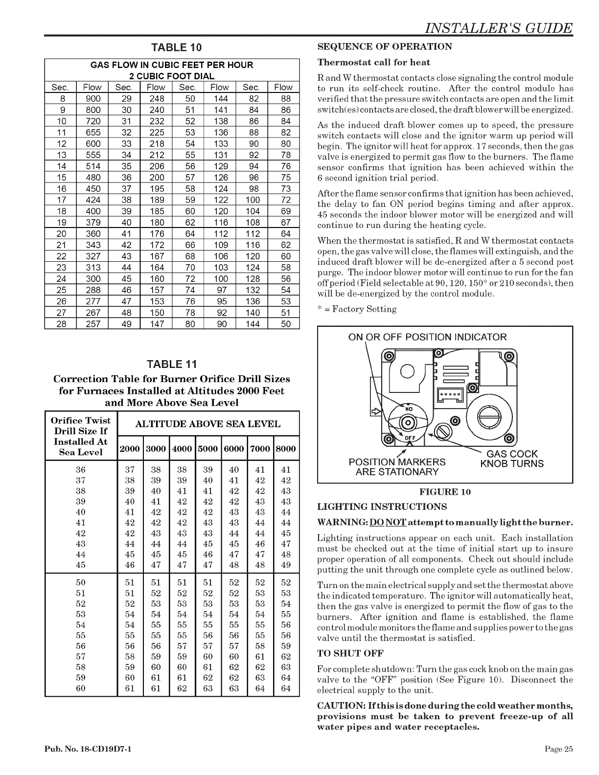
TABLE 10
GAS FLOW IN CUBIC FEET PER HOUR
2CUBIC FOOT DIAL
Sec. Flow Sec. Flow Sec. Flow Sec. Flow
8 900 29 248 50 144 82 88
9 800 30 240 51 141 84 86
10 720 31 232 52 138 86 84
11 655 32 225 53 136 88 82
12 600 33 218 54 133 90 80
13 555 34 212 55 131 92 78
14 514 35 206 56 129 94 76
15 480 36 200 57 126 96 75
16 450 37 195 58 124 98 73
17 424 38 189 59 122 100 72
18 400 39 185 60 120 104 69
19 379 40 180 62 116 108 67
20 360 41 176 64 112 112 64
21 343 42 172 66 109 116 62
22 327 43 167 68 106 120 60
23 313 44 164 70 103 124 58
24 300 45 160 72 100 128 56
25 288 46 157 74 97 132 54
26 277 47 153 76 95 136 53
27 267 48 150 78 92 140 51
28 257 49 147 80 90 144 50
TABLE 11
Correction Table for Burner Orifice Drill Sizes
for Furnaces Installed at Altitudes 2000 Feet
and More Above Sea Level
Orifice Twist
Drill Size If
Installed At
Sea Level
36
37
38
39
40
41
42
43
44
45
50
51
52
53
54
55
56
57
58
59
60
ALTITUDE ABOVE SEA LEVEL
2000 3000 4000 5000 6000 7000 8000
37 38 38 39 40 41 41
38 39 39 40 41 42 42
39 40 41 41 42 42 43
40 41 42 42 42 43 43
41 42 42 42 43 43 44
42 42 42 43 43 44 44
42 43 43 43 44 44 45
44 44 44 45 45 46 47
45 45 45 46 47 47 48
46 47 47 47 48 48 49
51 51 51 51 52 52 52
51 52 52 52 52 53 53
52 53 53 53 53 53 54
54 54 54 54 54 54 55
54 55 55 55 55 55 56
55 55 55 56 56 55 56
56 56 57 57 57 58 59
58 59 59 60 60 61 62
59 60 60 61 62 62 63
60 61 61 62 62 63 64
61 61 62 63 63 64 64
INSTALLER 'S GUIDE
SEQUENCE OF OPERATION
Thermostat call for heat
R and W thermostat contacts close signaling the control module
to run its self-check routine. After the control module has
verified that the pressure switch contacts are open and the limit
switch(es) contacts are closed, the draft blower will be energized.
As the induced draft blower comes up to speed, the pressure
switch contacts will close and the ignitor warm up period will
begin. The ignitor -will heat for approx. 17 seconds, then the gas
valve is energized to permit gas flow to the burners. The flame
sensor confirms that ignition has been achieved within the
6 second ignition trial period.
After the flame sensor confirms that ignition has been achieved,
the delay to fan ON period begins timing and after approx.
45 seconds the indoor blower motor will be energized and will
continue to run during the heating cycle.
When the thermostat is satisfied, R and W thermostat contacts
open, the gas valve will close, the flames will extinguish, and the
induced draft blower -will be de-energized after a 5 second post
purge. The indoor blower motor will continue to run for the fan
offperiod (Field selectable at 90,120,150" or 210 seconds), then
will be de-energized by the control module.
* = Factory Setting
ON OR OFF POSITION INDICATOR
,t
POSITION MARKERS
ARE STATIONARY
GAS COCK
KNOB TURNS
FIGURE 10
LIGHTING INSTRUCTIONS
WARNING: DO NOT attempt to manually light the burner.
Lighting instructions appear on each unit. Each installation
must be checked out at the time of initial start up to insure
proper operation of all components. Check out should include
putting the unit through one complete cycle as outlined below.
Turn on the main electrical supply and set the thermostat above
the indicated temperature. The ignitor will automatically heat,
then the gas valve is energized to permit the flow of gas to the
burners. After ignition and flame is established, the flame
control module monitors the flame and supplies power to the gas
valve until the thermostat is satisfied.
TO SHUT OFF
For complete shutdown: Turn the gas cock knob on the main gas
valve to the "OFF" position (See Figure 10). Disconnect the
electrical supply to the unit.
CAUTION: If this is done during the cold weather months,
provisions must be taken to prevent freeze-up of al!
water pipes and water receptacles.
Pub. No. 18-CD19D7-1 Page 25
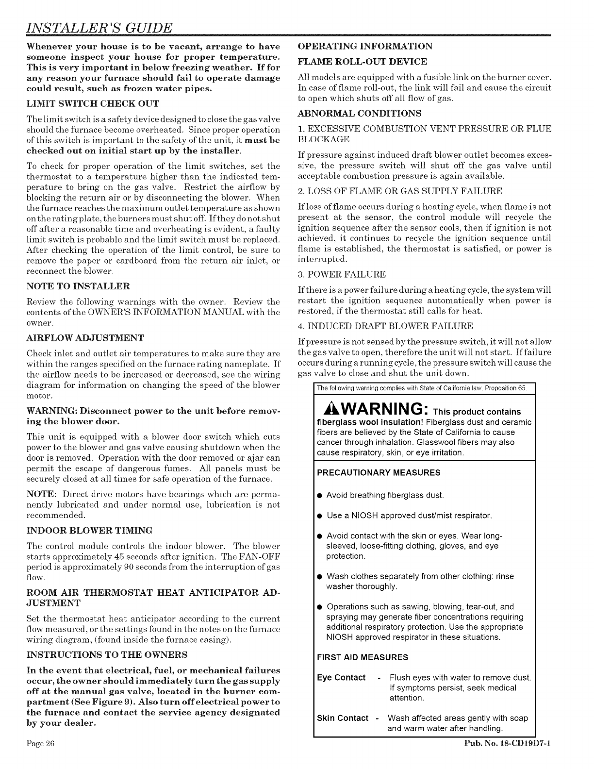
INSTALLER 'S GUIDE
Whenever your house is to be vacant, arrange to have
someone inspect your house for proper temperature.
This is very important in below freezing weather. If for
any reason your furnace should fail to operate damage
could result, such as frozen water pipes.
LIMIT SWITCH CHECK OUT
The limit switch is a safety device designed to close the gas valve
should the furnace become overheated. Since proper operation
of this switch is important to the safety of the unit, it must be
checked out on initial start up by the installer.
To check for proper operation of the limit switches, set the
thermostat to a temperature higher than the indicated tem-
perature to bring on the gas valve. Restrict the airflow by
blocking the return air or by disconnecting the blower. When
the furnace reaches the maximum outlet temperature as shown
on the rating plate, the burners must shut off. If they do not shut
off after a reasonable thne and overheating is evident, a faulty
limit switch is probable and the limit switch must be replaced.
After checking the operation of the limit control, be sure to
remove the paper or cardboard from the return air inlet, or
reconnect the blower.
NOTE TO INSTALLER
Review the following warnings with the owner. Review the
contents of the OWNER'S INFORMATION MANUAL with the
owner.
AIRFLOW ADJUSTMENT
Check inlet and outlet air temperatures to make sure they are
within the ranges specified on the furnace rating nameplate. If
the airflow needs to be increased or decreased, see the wiring
diagram for information on changing the speed of the blower
motor.
WARNING: Disconnect power to the unit before remov-
ing the blower door.
This unit is equipped with a blower door switch which cuts
power to the blower and gas valve causing shutdown when the
door is removed. Operation with the door removed or ajar can
permit the escape of dangerous fumes. All panels must be
securely closed at all times for safe operation of the furnace.
NOTE: Direct drive motors have bearings which are perma-
nently lubricated and under normal use, lubrication is not
recommended.
INDOOR BLOWER TIMING
The control module controls the indoor blower. The blower
starts approximately 45 seconds after ignition. The FAN-OFF
period is approximately 90 seconds from the interruption of gas
flO-W.
ROOM AIR THERMOSTAT HEAT ANTICIPATOR AD-
JUSTMENT
Set the thermostat heat anticipator according to the current
flow measured, or the settings found in the notes on the furnace
wiring diagram, (found inside the furnace casing).
INSTRUCTIONS TO THE OWNERS
In the event that electrical, fuel, or mechanical failures
occur, the owner should immediately turn the gas supply
off at the manual gas valve, located in the burner com-
partment (See Figure 9). Also turn off electrical power to
the furnace and contact the service agency designated
by your dealer.
OPERATING INFORMATION
FLAME ROLL-OUT DEVICE
All models are equipped with a fusible link on the burner cover.
In case of flame roll-out, the link will fail and cause the circuit
to open which shuts off all flow of gas.
ABNORMAL CONDITIONS
1. EXCESSIVE COMBUSTION VENT PRESSURE OR FLUE
BLOCKAGE
If pressure against induced draft blower outlet becomes exces-
sive, the pressure switch will shut off the gas valve until
acceptable combustion pressure is again available.
2. LOSS OF FLAME OR GAS SUPPLY FAILURE
If loss of flame occurs during a heating cycle, when flame is not
present at the sensor, the control module will recycle the
ignition sequence after the sensor cools, then if ignition is not
achieved, it continues to recycle the ignition sequence until
flame is established, the thermostat is satisfied, or power is
interrupted.
3. POWER FAILURE
If there is a power failure during a heating cycle, the system will
restart the ignition sequence automatically when power is
restored, if the thermostat still calls for heat.
4. INDUCED DRAFT BLOWER FAILURE
If pressure is not sensed by the pressure switch, it will not allow
the gas valve to open, therefore the unit will not start. If failure
occurs during a running cycle, the pressure switch will cause the
gas valve to close and shut the unit down.
The following warning complies with State of California taw, Proposition 65.
WARNING: T.isproduct contains
fiberglass wool insulation! Fiberglass dust and ceramic
fibers are believed by the State of California to cause
cancer through inhalation. Glasswool fibers may also
cause respiratory, skin, or eye irritation.
PRECAUTIONARY MEASURES
• Avoid breathing fiberglass dust.
• Use a NtOSH approved dust/mist respirator.
• Avoid contact with the skin or eyes. Wear long-
sleeved, loose-fitting clothing, gloves, and eye
protection.
• Wash clothes separately from other clothing: rinse
washer thoroughly.
Operations such as sawing, blowing, tear-out, and
spraying may generate fiber concentrations requiring
additional respiratory protection. Use the appropriate
NiOSH approved respirator in these situations.
FIRST AID MEASURES
Eye Contact Flush eyes with water to remove dust.
If symptoms persist, seek medical
attention.
Skin Contact -Wash affected areas gently with soap
and warm water after handling.
Page 26 Pub. No. 18-CD19D7-1

INSTALLER 'S GUIDE
FIELD WiRiNG DIAGRAM FOR HEATING ONLY
NOTES
I. BE SURE POWER SUPPLY AGREES WITH EQUIPMENT NAMEPLATEISL
2. LOW VOLTAGE {Z4V.) WIRING TO BE NO. (8 A. W. G. MIN.
3. GROUNDING OF EQUIPMENT MUST COMPLY WITH LOCAL CODES.
4. SET THERMOSTAT HEAT ANTICIPATOR PER UNIT WIRING DIAGRAM.
TO 1(5 VOLT
POWER SUPPLY
SAIL SWITCH HUMIDISTAT
AY28 X119
F'----- _"'5-q _L':-
]LINE VOLTAGE SAIL SWITCH
RED OR # {MOUNTED IN RETURN AIR DUCT)
j L__
_"_'"1 .k, L TO _15 VOLT
IL,_ [POWER SUPPLY
ELECTRONIC AIR
CLEANER (OPTIONAL) .#
POWER
HUMIDIFIER
{OPT IONAL )
NOTE 4
HEATING THERMOSTAT (OR HEATING )
WITH FAN SWITCH THERMOSTAT
[---
I
I
I
INTERG_
CONTROL THERMOSTAT I
.TERMINALS I
GROUNDI !
SC R E W ?_1 BLAC_ _WHITE j.__
- ....
JUNCTIONBOX _ LILH ILN,)
T
TO 115V., I PH., 60 HZ.,
POWER SUPPLY PER
LOCAL CODES
FURNACE
] ALTERNATE HOOKUP FOR MODEL BEFMO
RED OR /-_ iOL-._R-_R200 ELECTRONIC AIR CLEANER
BLACK _L_ _ .... I_H=_
RELAY KIT I "[.TO I15
WHIT__H.LTEJ L BAYZ4XO433L LN {"POWER
ELECTRONIC AIR
CLEANER IOPTIONALI
VOLT
SUPPLY
INTER-COMPONENT WIRING
.... 24 V. "_ FIELD
LINE V.JWIRING
24. V. "_ FACTORY
_LINE V.JWIRING
From Dwg. 21B340433 Rev. 0
FIELD WIRING DIAGRAM FOR HEATING/COOLING
(OUTDOOR SECTION WITHOUT TRANSFORMER)
NOTES:
1. BE SURE POWER SUPPLY AGREES WITH EQUIPMENT NAMEPLATE(S).
2. LOW VOLTAGE (24V.) WIRING TO BE NO. 18 A.W.G. MIN.
3. GROUNDING OF EQUIPMENT MUST COMPLY WITH LOCAL CODES.
4. SET THERMOSTAT HEAT ANTICIPATOR PER UNIT WIRING DIAGRAM.
5. THE "Y" TERMINAL FROM THE THERMOSTAT MUST BE WIRED TO
THE "Y" TERMINAL OF THE FURNACE CONTROL FOR PROPER
BLOWER OPERATION DURING COOLING.
SAIL SWITCH HUMIDISTAT
AYZ8XII9
li--/--7_ _-_-_-
TO 115 VOLT -- Jl i i POWER
POWER SUPPLY LNEUTRAL p,.__. J_ i i HUMIDIFIER
..... _ _ (OPT IONALI
LINE VOLTAGE SAIL SWITCH
RED OR _ I (MOUNTED IN RETURN AIR DUCT)
TO lib VOLT
ELECTRONIC AIR LJPOWER SUPPLY
CLEANER IOPT IONALI
POWER
SUPPLY
r_._?___ A-NOTE N5
-----I OTE 4
I _ _ _____I El HEATING-COOLING
/ Y_-T .... ;1 THERMOSTAT
IBIIf" .... T -- -- T "L_I
II I_ ----
....... i II I F--
LOW VOLTAGE j _l I I I _
AIR CONDITIONING ii I
OUTDOOR SECTION II i
WITHOUT TRANSFORMER
INTERGRATED FURNACE
CONTROL THERMOSTAT
TERM NKLS,
GROUND [i
SCREW_
FURNACE
BLACK--_ ;!--WHITE
k)JUNCTION
Y BOX
TO ItSV., t PH., 60 HZ.,
POWER SUPPLY PER
LOCAL CODES
i ALTERNATE HOOKUP FOR MODEL BEFI40
RED OR _ [OR 20_0_ ELECTRONIC AIR CLEANER
.... ±"_,
Z_ RELAY KIT II L [TO 1t5
WHITE ILBAY24xO43J_[ N)"POWER
ELECTRONIC AIR
CLEANER (OPTIONALI
VOLT
SUPPLY
INTER-COMPONENT WIRING
24 V. "_ FIELD
----LINE V,.ff WIRING
24 V. "L FACTORY
--LINE v..f" WIRING
From Dwg. 21B330432 Rev. 0
Pub. No. 18-CD19D7-1 Page 27
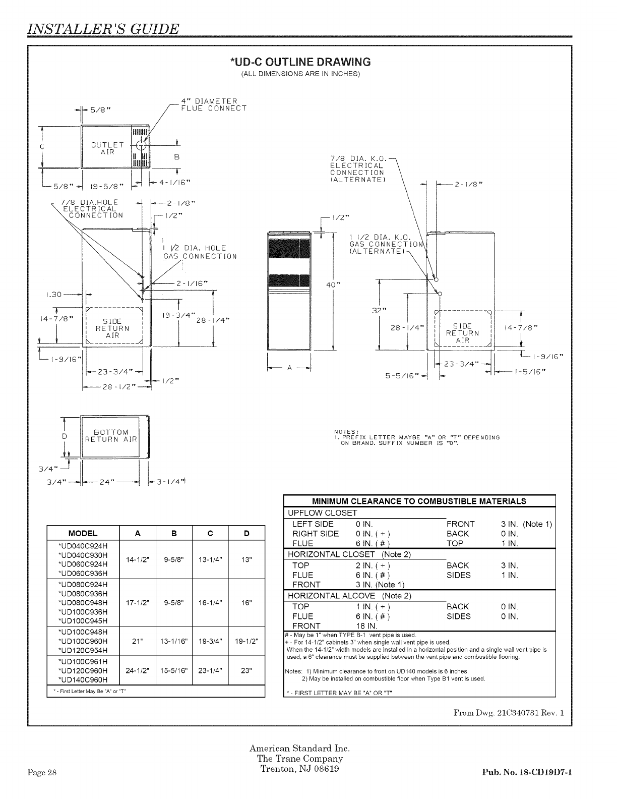
INSTALLER 'S GUIDE
*UD-C OUTLINE DRAWING
(ALL DIMENSIONS ARE IN INCHES)
4" DIAMETER
1I_'-5/8 '' S FLUE CONNECT
AIR
" 19-5/8" _ ----K
7/8 DIA.HOLE
ELECTRICAL
CONNECTION
I/8 '"
I [/2 DIA. HOLE
GAS CONNECTION
7/8 DIA. K.O.--_
ELECTRICAL \
C_OLN#E##AITO#, _
2lj- \
I t/2 DIA. K.O.
GAS CONNECTIO
1 (ALTERNATE}_
40" 7 --
32" _---
28 - t/4""
1-5/16"
-! BOTTOM
3 - i/4"1
MODEL A B C D
*UD040C924H
*UD040C93OH 14-1/2" 9-5/8" 13-1/4" 13"
*UD06OC924H
*UD060C936H
*UD080C924H
*UD080C936H
*UD080C948H 17-1/2" 9-5/8" 16-1/4" 16"
*UD1O0C936H
*UD1O0C945H
*UD1O0C948H
*UD1O0C960H 21" 13-1/16" 19-3/4" 19-1/2"
*UD120C954H
*UD1O0C961H
*UD120C960H 24-1/2" 15-5/16" 23-1/4" 23"
*UD140C960H
* - First Letter May Be "A" or "T"
N OTES :
I. PREFIX LETTER MAYBE "A" OR "T" DEPENDING
ON BRAND. SUFFIX NUMBER IS "0%
MINIMUM CLEARANCE TO COMBUSTIBLE MATERIALS
UPFLOW CLOSET
LEFT SIDE 0 IN. FRONT 3 IN. (Note 1)
RIGHT SIDE 0 IN. ( + ) BACK 0 IN.
FLUE 6 IN, (#) TOP 1 IN,
HORIZONTAL CLOSET (Note 2)
TOP 2 IN. ( + ) BACK 3 IN.
FLUE 6 IN. (#) SIDES 1 IN,
FRONT 3 IN, (Note 1)
HORIZONTAL ALCOVE (Note 2)
TOP 1 IN. ( + ) BACK 0 IN.
FLUE 6 IN. (#) SIDES 0 IN,
FRONT 18 IN,
# - May be 1"when TYPE B-1 vent pipe is used.
+ - For 14-1/2" cabinets 3" when single watt vent pipe is used.
When the 14-1/2" width models are installedin a horizontal position and asingle wall vent pipe is
used, a 6" clearance must be supplied between the vent pipe and combustible flooring.
Notes: 1) Minimum clearance to front on UD140 models is 6inches.
2) May be installed on combustible floor when Type Bf vent is used.
- FIRST LETTER MAY BE "A" OR "T"
From Dwg. 21C340781 Rev. 1
Page 28
American Standard Inc.
The Trane Company
Trenton, NJ 08619 Pub. No. 18-CD19D7-1
