TRANE Air Conditioner/heat Pump(outside Unit) Manual L0903229
User Manual: TRANE TRANE Air conditioner/heat pump(outside unit) Manual TRANE Air conditioner/heat pump(outside unit) Owner's Manual, TRANE Air conditioner/heat pump(outside unit) installation guides
Open the PDF directly: View PDF ![]() .
.
Page Count: 8
18-AC52D5-1
Condensing Un
2TTB0530-536M & 2TTB0524-536AA
ALL phases of this installation must comply with NATIONAL, STATE AND LOCAL CODES
IMPORTANT -- This Document is customer property and is to remain with this unit. Please return to service information
pack upon completion of work.
These instructions do not cover all variations in
systems nor provide for every possible contingency to
be met in connection with installation. All phases of
this installation must comply with NATIONAL, STATE
AND LOCAL CODES. Should further information be
desired or should particular problems arise which are not
covered sufficiently for the purchaser's purposes, the matter
should be referred to your installing dealer or local distributor.
A. GENERAL
The following instructions cover 2TTB05; Condensing Units.
NOTE:
These outdoor units may be used with indoor units
equipped with Thermostatic Expansion Valve or Accutron rM
Flow Control Check Valve (E C.C.V.) assembly for refrigerant
flow control only.
Check for transportation damage after unit is uncrated.
Report promptly, to the carrier, any damage found to the unit.
To determine the electrical power requirements of the unit,
refer to the nameplate of the unit. The electrical power
available must agree with that listed on the nameplate.
B. LOCATION &PREPARATION OFTHE UNiT
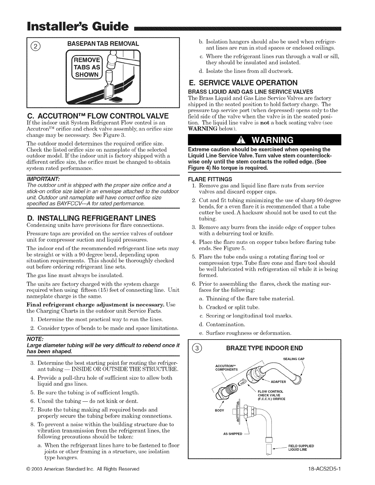
1. When removing unit from the pallet, notice the tabs on
the basepan. Remove tabs by cutting with a sharp tool as
shown in Figure 2 (see page 2).
2. The unit should be set on a level support pad at least as
large as the unit base pan, such as a concrete slab. If this
is not the application used please refer to application
bulletin "Trane APB2001-02".
3. The support pad must NOT be in direct contact with any
structure. Unit must be positioned a minimum of 12"
from any wall or surrounding shrubbery to insure
adequate airflow. Clearance must be provided in front of
control box (access panels) & any other side requiring
service access to meet National Electrical Code. Also,
the unit location must be far enough away from any
structure to prevent excess roof run-off water from
pouring directly on the unit. Do not locate unit(s) close to
bedroom(s).
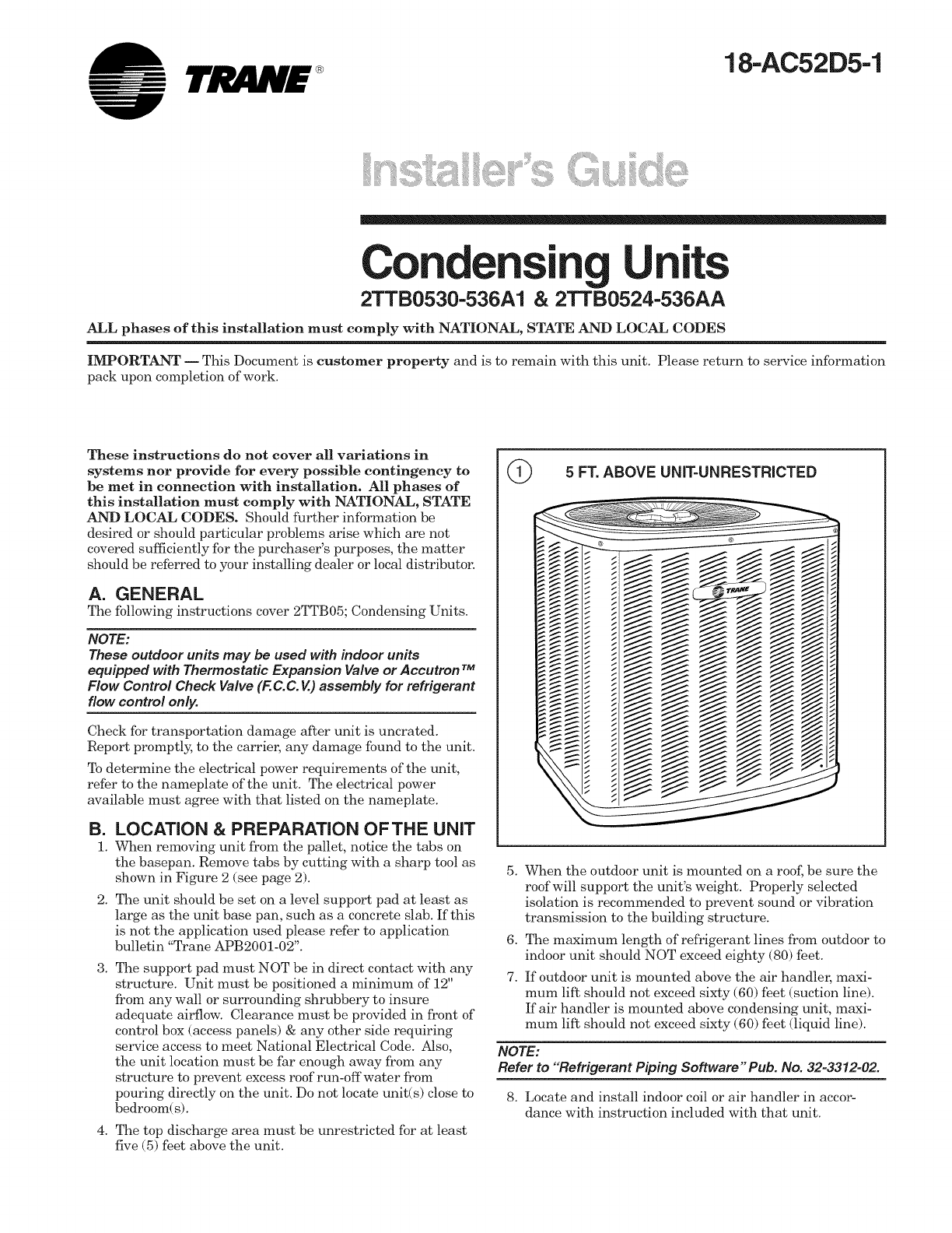
4. The top discharge area must be unrestricted for at least
five (5) feet above the unit.
5 FT. ABOVE UNIT=UNRESTRICTED
5,
6,
7.
When the outdoor unit is mounted on a roof, be sure the
roof will support the unit's weight. Properly selected
isolation is recommended to prevent sound or vibration
transmission to the building structure.
The maximum length of refrigerant lines from outdoor to
indoor unit should NOT exceed eighty (80) feet.
If outdoor unit is mounted above the air handler, maxi-
mum lift should not exceed sixty (60) fhet (suction line).
If air handler is mounted above condensing unit, maxi-
mum lift should not exceed sixty (60) feet (liquid line).
NOTE:
Refer to "Refrigerant Piping Software" Pub. No. 32=3312=02.
8. Locate and install indoor coil or air handler in accor-
dance with instruction included with that unit.
|nsta||er's Guide
@
C. ACCUTRON TM FLOW CONTROL VALVE
If the indoor unit System Refrigerant Flow control is an
Aceutron TM orifice and check valve assembly, an orifice size
change may be necessary. See Figure 3.
The outdoor model determines the required orifice size.
Check the listed orifice size on nameplate of the selected
outdoor model. If the indoor unit is factory shipped with a
different orifice size, the orifice must be changed to obtain
system rated performance.
IMPORTANT:
The outdoor unit is shipped with the proper size orifice and a
stick-on orifice size label in an envelope attached to the outdoor
unit. Outdoor un# nameplate will have correct orifice size
specified as BAYFCCV---A for rated performance.
D. INSTALLING REFRIGERANT LINES
Condensing units have provisions for flare connections.
Pressure taps are provided on the service valves of outdoor
unit for compressor suction and liquid pressures.
The indoor end of the recommended refrigerant line sets may
be straight or with a 90 degree bend, depending upon
situation requirements. This should be thoroughly checked
out before ordering refrigerant line sets.
The gas line must always be insulated.
The units are factory charged with the system charge
required when using fifteen (15) feet of connecting line. Unit
nameplate charge is the same.
Final refrigerant charge adjustment is necessary. Use
the Charging Charts in the outdoor unit Service Facts.
1. Determine the most practical way to run the lines.
2. Consider types of bends to be made and space limitations.
NOTE:
Large diameter tubing will be very difficult to rebend once it
has been shaped.
3. Determine the best starting point for routing the refriger-
ant tubing -- INSIDE OR OUTSIDE THE STRUCTURE.
4. Provide a pull-thru hole of sufficient size to allow both
liquid and gas lines.
5. Be sure the tubing is of sufficient length.
6. Uncoil the tubing -- do not kink or dent.
7. Route the tubing making all required bends and
properly secure the tubing before making connections.
8. To prevent a noise within the building structure due to
vibration transmission from the refrigerant lines, the
following precautions should be taken:
a. When the refrigerant lines have to be fastened to floor
joists or other framing in a structure, use isolation
type hangers.
b. Isolation hangers should also be used -when refriger-
ant lines are run in stud spaces or enclosed ceilings.
c. Where the refrigerant lines run through a wall or sill,
they should be insulated and isolated.
d. Isolate the lines from all ductwork.
E. SERVICE VALVE OPERATION
BRASS LIQUID AND GAS LINE SERVICE VALVES
The Brass Liquid and Gas Line Service Valves are factory
shipped in the seated position to hold factory charge. The
pressure tap service port (when depressed) opens only to the
field side of the valve when the valve is in the seated posi-
tion. The liquid line valve is not a back seating valve (see
WARNING below).
Extreme caution should be exercised when opening the
Liquid Line Service Valve. Turn valve stem counterclock-
wise only until the stem contacts the rolled edge. (See
Figure 4) No torque is required.
FLARE FITTINGS
1. Remove gas and liquid line flare nuts from service
valves and discard copper caps.
2,
3,
4.
5.
Cut and fit tubing minimizing the use of sharp 90 degree
bends, for a even flare it is recommended that a tube
cutter be used. A hacksaw should not be used to cut the
tubing.
Remove any burrs from the inside edge of copper tubes
with a deburring tool or knife.
Place the flare nuts on copper tubes before flaring tube
ends. See Figure 5.
Flare the tube ends using a rotating flaring tool or
compression type. Tube flare cone and flare tool should
be well lubricated with refrigeration oil while it is being
formed.
6, Prior to assembling the flares, check the mating sur-
faces for the following:
a. Thinning of the flare tube material.
b. Cracked or split tube.
c. Scoring or longitudinal tool marks.
d. Contamination.
e. Surface roughness or deformation.
®BRAZE TYPE iNDOOR END
SEALING CAP
s SN
[_ FIELD SUPPLIED
LIQUID LINE
© 2003 American Standard Inc. All Rights Reserved 18-AC52D5-1
|nstaIIer's Guide
cAP SERVICE VALVE
L, L
ROLLED EDGE
TO CAPTURE STEM
LIQUIDUNE
\\
:)ISCARD CAP
SUCTION LINE j
NOTE:
If any of these conditions are observed, the part is defec-
tive and must be replaced.
7. The mating faces of the fitting should be joined squarely,
with no lateral or longitudinal strain on the fitting.
8. The nut should be torqued per the values on the outline
drawing (page 6).
9. When tightening the flare joints two wrenches must be
used. The fitting must be securely supported by the
stationary wrench.
10. Flared joints are not field repairable. If any damage is
found, that portion must be cut from the tubing and the
flare remade.
LEAK CHECK
IMPORTANT:
Replace pressure tap port valve core before attaching hoses for
evacuation.
After the installing of refrigerant lines to both the outdoor
and indoor unit is completed, the field connections must be
checked for leaks. Pressurize through the service valve ports,
the indoor unit and field refrigerant lines with dry nitrogen
to 350-400 psi. Use soap bubbles or other leak-checking
methods to see that all field joints are leak-free! If not,
release pressure; then repair!
SYSTEM EVACUATION
NOTE:
Since the outdoor unit has a refrigerant charge, the gas and
liquid line valves must remain closed.
1. Upon completion of leak check, evacuate the refrigerant
lines and indoor coil before opening the gas and liquid
line valves.
2. Attach appropriate hoses from manifold gauge to gas
and liquid line pressure taps.
NOTE:
Unnecessary switching of hoses can be avoided and
complete evacuation of all lines leading to sealed system
can be accomplished with manifold center hose and
connecting branch hose to a cylinder of HCFC-22 and
vacuum pump.
3. Attach center hose of manifold gauges to vacuum pump.
4.
5.
6.
7.
Evacuate until the micron gauge reads no higher than
350 microns.
Close off valve to vacuum pump and observe the micron
gauge. If gauge pressure rises above 500 microns in one (1)
minuS, then evacuation is incomple_ or sys_m has a leak.
If vacuum gauge does not rise above 500 microns in
one (1) minute, the evacuation should be complete.
With vacuum pump and micron gauge blanked off; open
valve on HCFC-22 cylinder and charge refrigerant lines
and indoor coil with vapor to tank pressure of HCFC-22
supply.
NOTE:
DO NOT VENT REFRIGERANT INTO THE ATMOSPHERE.
8. Close valve on HCFC-22 supply cylinder. Close valves
on manifold gauge set and remove refrigerant charging
hoses from liquid and gas pressure tap ports.
NOTE:
A 3/16" Allen wrench is required to open liquid line service
valve. A I/4" Open End or Adjustable wrench is required
to open gas line valve. A 3/4" Open End wrench is required
to take off the valve stem cap.
9. The liquid line shut-off valve can now be opened. Remove
shut-off valve cap. Fully insert hex wrench into the stein
m_d backout coun_rclockwise until valve s_m just touches
rolled edge (approximately five [5] turns) observing
WARNING statement on page 2. See Figure 4.
10. Replace liquid service pressure tap port cap and valve
stem cap. These caps MUST BE REPLACED to
prevent leaks. Replace valve stem cap and pressure tap
cap finger tight, then tighten an additional 1/6 turn.
11. The gas valve can now be opened. For a ball type gas
valve, open the gas valve by removing the shut-offvalve
cap and turning the valve stem 1/4 turn counterclock-
wise, using 1/4" Open End or Adjustable wrench. See
Figure 5. For brass gas line service valve opening,
follow 9 and 10 above. See Figure 4.
12. The gas valve is now open for refrigerant flow. Replace
valve stein cap to prevent leaks. Again, these caps
MUST BE REPLACED to prevent leaks. Replace valve
stem cap and pressure tap cap finger tight, then tighten
an additional 1/6 turn. See Figure 5.
If refrigerant lines are longer than 15 feet and/or a
diffhrent size than recommended, it will be necessary to
adjust system refrigerant charge upon completion of
installation. See unit Service Facts.
FLARED TUBE
PLACED NUT ON
TUBE BEFORE
90°
_.09 TYR
FLAT
18-AC52D5-1 3
|nsta||er's Guide
F. ELECTRICAL CONNECTIONS
When installing or servicing this equipment, ALWAYS
exercise basic safety precautions to avoid the possibility of
electric shock.
1. Power -wiring and grounding of equipment must comply
with local codes.
2. Power supply must agree with equipment nameplate.
3. Install a separate disconnect switch at the outdoor unit.
4. Ground the outdoor unit per local code requirements.
5. Provide flexible electrical conduit whenever vibration
transmission may create a noise problem within the
structure.
6. Mount the indoor thermostat in accordance with instruc-
tion included with the thermostat. Wire per appropriate
hook-up diagram (included in these instructions).
G. COMPRESSOR START UP
After all electrical wiring is complete, SET THE THERMO-
STAT SYSTEM SWITCH IN THE OFF POSITION SO
COMPRESSOR WILL NOT RUN, and apply power by closing
the system main disconnect switch. This will activate the
compressor sump heat (where used). Do not change the
Thermostat System Switch until power has been applied for
one (1) hour. Following this procedure will prevent potential
compressor overload trip at the initial start-up.
H. OPERATIONAL AND CHECKOUT
PROCEDURES
Final phases of this installation are the unit Operational and
Checkout Procedures which are found in this instruction (see
page 8). To obtain proper performance, all units must be
operated and charge adjustments made in accordance with
procedures found in the Service Facts.
I. ELECTRIC HEATERS
Electric heaters, if used, are to be installed in the air han-
dling device according to the instructions accompanying the
air handler and the heaters.
J. START CONTROL
Some models have quick start components which are factory
installed. For models that do not have factory installed start
components, provisions are made for a field installed start kit
accessory. When adding an accessory, follow the instructions
provided with the kit.
K. OUTDOOR THERMOSTAT
An outdoor thermostat TAYSTAT250B may be field installed.
For data, see wiring diagram attached to unit and instruction
sheet packaged with outdoor thermostat.
L. SEACOAST SHIELD
BAYSEAC001 (Seacoast Kit) is available for application on
units installed -within one mile of salt water, including
seacoasts and inland waterways.
M. TROUBLESHOOTING
TROUBLESHOOTING CHART -- WHAT TO CHECK
SYSTEMFAULTS
REFRIGERANTCbRCUIT
ELECTRICAL
P-Prim_r¢ C_us_s S-Sec0nd_ryCauses
4 18-AC52D5-1
|nsta||er's Guide
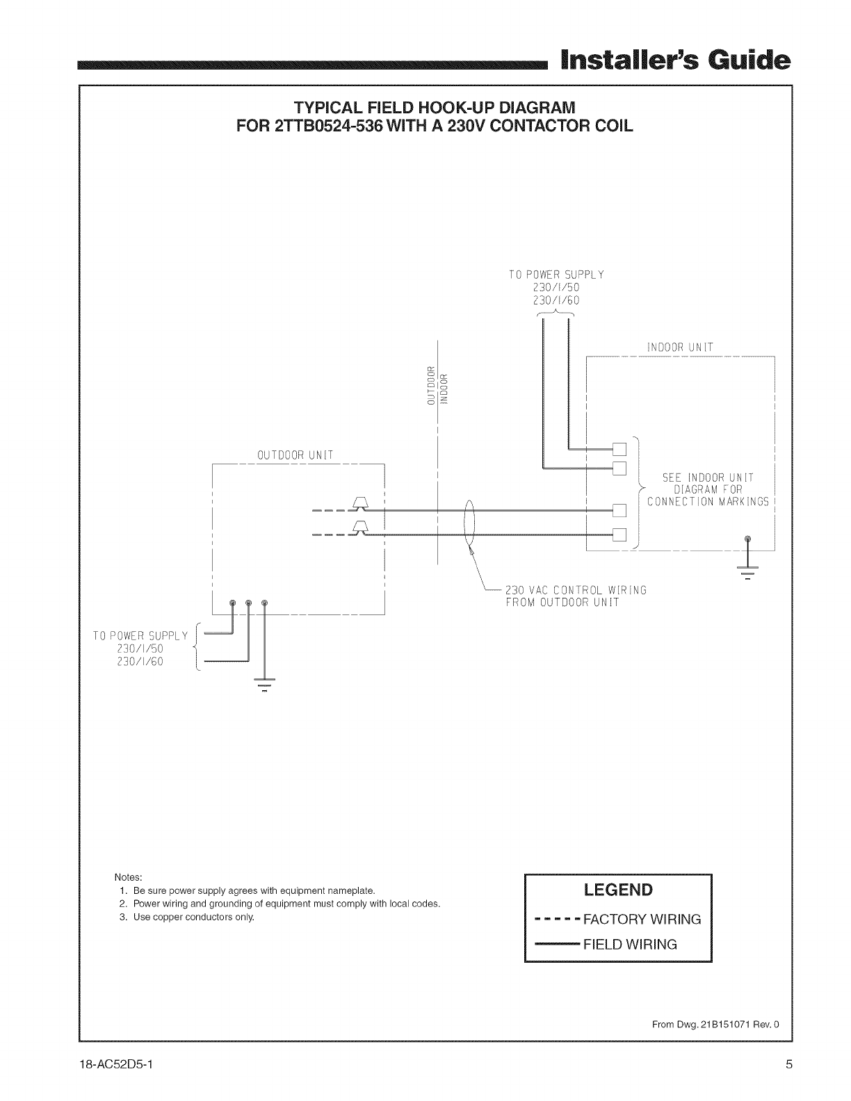
TYPICAL FIELD HOOK-UP DIAGRAM
FOR 2TTB0524-536 WiTH A 230V CONTACTOR COiL
TO POWER SUPPLY
230/I/50
230/I/60
TO POWER SUPPLY
230/I/50
230/I/80
OUTDOOR UNIt 1
NDOOR JNT
\\\
%
_230 VAC CONTROL WIRING
FROM OUTDOOR UNIT
SEE INDOOR UN T
DIAGRAM FOR
¢'C
CONNFC]ION MARK N_x::/
Notes:
1. Be sure power supply agrees with equipment nameplate.
2. Power wiring and grounding of equipment must comply with local codes.
3. Use copper conductors only.
LEGEND
..... FACTORY WIRING
_ FIELD WIRING
From Dwg. 21 B1,51071 Rev. 0
18-AC52D5-1 5
|nsta||er's Guide
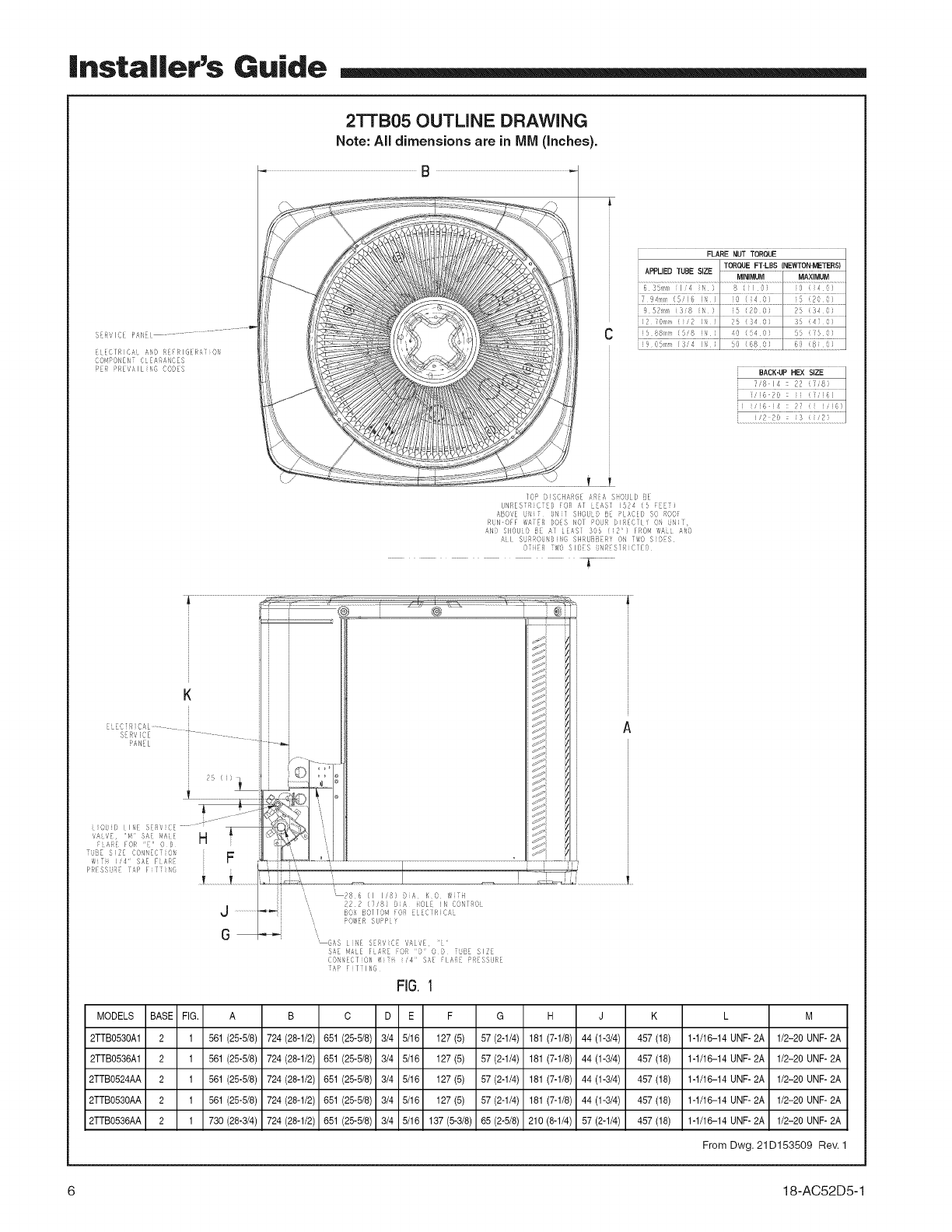
2TTB05 OUTLINE DRAWING
Note: All dimensions are in IVllVl(inches).
SFRVICE PAN_i
_LECIRICAL A_O tE_RIG[RATiO_
¢OMPONEN_ CLEARANCLS
PER PREVAILING CODFS
FLARE NUT TORQUE
lOP 5iS(}HARGE A A S ()ULD ;_E
UNRES R CTED FOR AT EASY i524 {5 i)
ABOVE UNi; UNJi SIIOULD IE PLACE[} SO ROOF
_UN OFF wArE£ ')OES NOI PO_ I)JRECILY ON ii_i],
ANi} SIIOUiD I_ AI LEASI 30D (12 ¸¸) FJ_OM WAiL ANi)
AJ[ SUR!OS_SJNG SHRUBB-I¥ O_ YWO Sii)_S
0{1i_ TWO SID[S _N_S]RiClED
T
U ...................._._
G
_72 (718} Di# iiOL[ Jl,i CONTROl
BOX B011@4 FO! ELE¢IRIC=\L
_OWER SUPPif
G£_S Life S'_ ',iCE WL?E, 'i
SA[ III,SLE FLARE FOR D ¸_ 0 D TUB[ SIZE
(_O_[_ECliON ?iii_i i¸¸'4 ¸' SA[_ FIA_i} PR{ISSHP]E
_!_i_ i i I JIN6
FiG.I
MODELS BASE FIG. A B C D E F G H J K L M
2TTB053OA1 2 1 561 (25-5/8) 724 (28-1/2) 651 (25-5/8) 3/4 5/16 127 (5) 57 (2-1/4) 181 (7-1/8) 44 (1-3/4) 457 (18) 1-1/16-14 UNF-2A 1/2-20 UNF- 2A
2TTB0536A1 2 1 561 (25-5/8) 724 (28-1/2) 651 (25-5/8) 3/4 5/16 127 (5) 57 (2-1/4) 181 (7-1/8) 44 (1-3/4) 457 (18) 1-1/16-14 UNF- 2A 1/2-20 UNF- 2A
2TTB0524AA 2 1 561 (25-5/8) 724 (28-1/2) 651 (25-5/8) 3/4 5/16 127 (5) 57 (2-1/4) 181 (7-1/8) 44 (1-3/4) 457 (18) 1-1/16-14 UNF- 2A 1/2-20 UNF- 2A
2TTB053OAA 2 1 561 (25-5/8) 724 (28-1/2) 651 (25-5/8) 3/4 5/16 127 (5) 57 (2-1/4) 181 (7-1/8) 44 (1-3/4) 457 (18) 1-1/16-14 UNF- 2A 1/2-20 UNF- 2A
2TTB0536AA 2 1 730 (28-3/4) 724 (28-1/2) 651 (25-5/8) 3/4 5/16 137 (5-3/8) 65 (2-5/8) 210 (8-1/4) 57 (2-1/4) 457 (18) 1-1/16-14 UNF-2A 1/2-20 UNF-2A
From Dwg. 21D153509 Rev. 1
6 18-AC52D5-1
|nstal|er's Guide
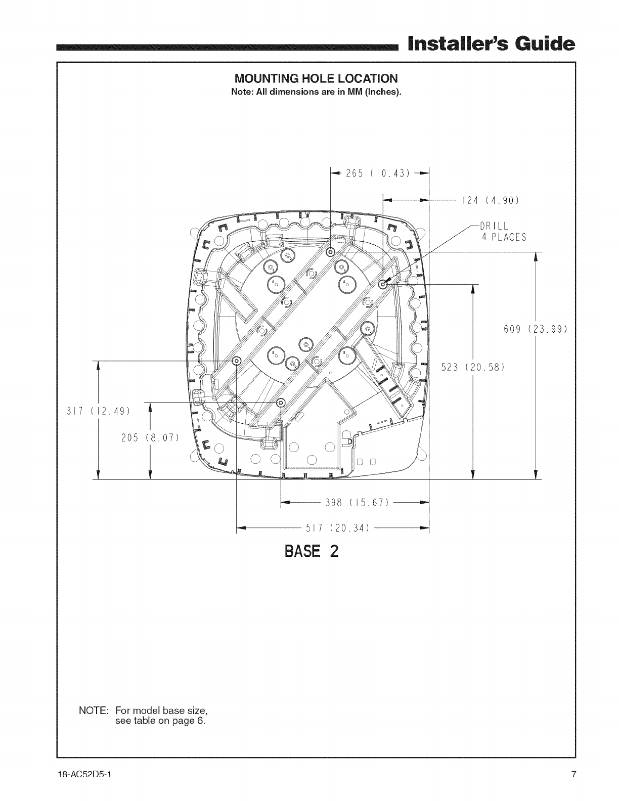
MOUNTING HOLE LOCATION
Note:All dimensionsare in IVllVl(Inches).
317 (12.49) l
2O5 (8,O7)
398
517 (20 34)
BASE 2
265 (10 43)
124 (4.90)
ILL
4 PLACES
15.67
523 (2O,58)
609 (23.99)
NOTE: For model base size,
see table on page 6.
18-AC52D5-1 7
|nsta||er's Guide
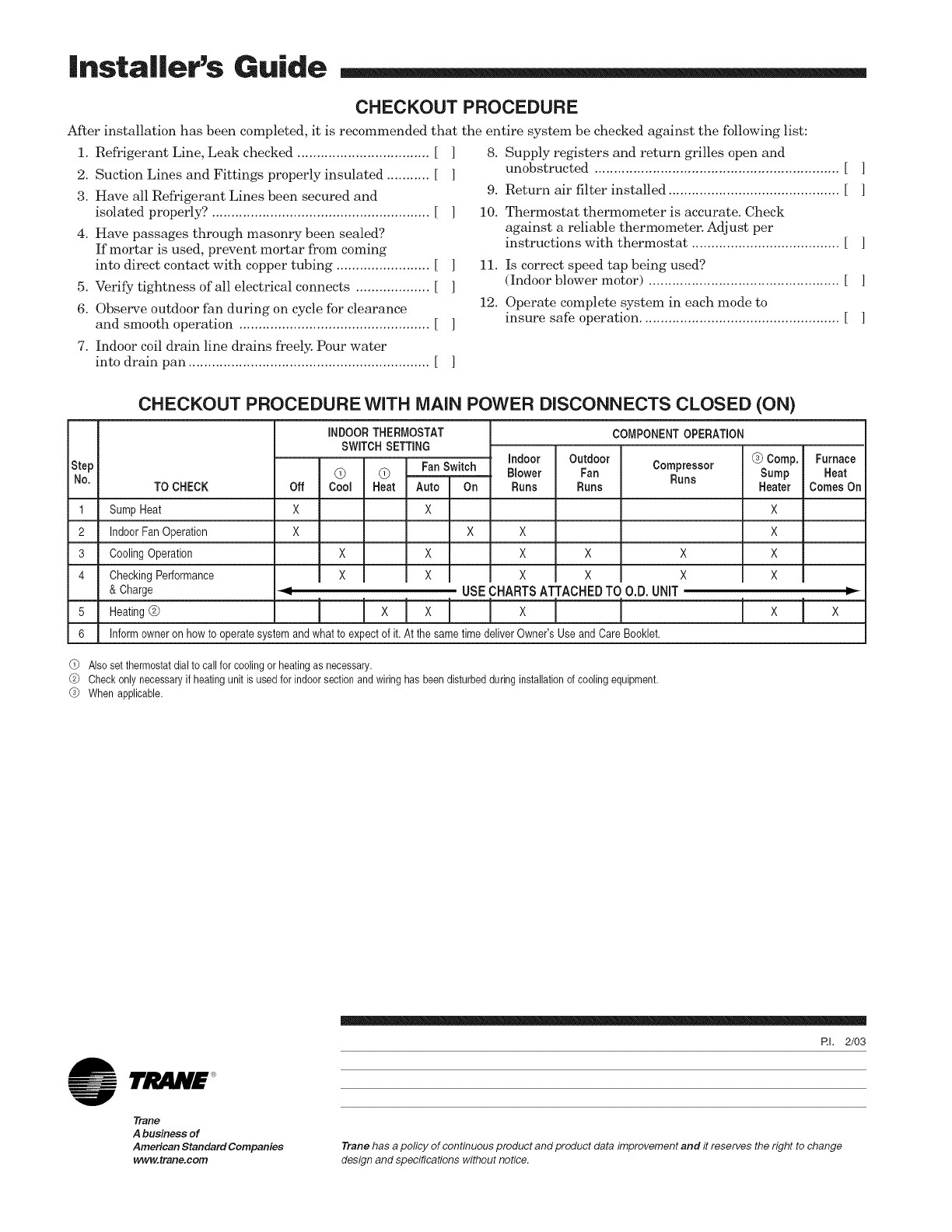
CHECKOUT PROCEDURE
After installation has been completed, it is recommended that the entire system be checked against the following list:
1. Refrigerant Line, Leak checked .................................. [
2. Suction Lines and Fittings properly insulated ........... [
3. Have all Refrigerant Lines been secured and
isolated properly? ........................................................ [
4. Have passages through masonry been sealed?
If mortar is used, prevent mortar from coining
into direct contact with copper tubing ........................ [
5. Verify tightness of all electrical connects ................... [
6. Observe outdoor fan during on cycle for clearance
and smooth operation ................................................. [
]
]
]
]
8. Supply registers and return grilles open and
unobstructed ............................................................... [ ]
9. Return air filter installed ............................................ [ ]
10. Thermostat thermometer is accurate. Check
against a reliable thermometer. Adjust per
instructions with thermostat ...................................... [ ]
11. Is correct speed tap being used?
(Indoor blower motor) ................................................. [ ]
12. Operate complete system in each mode to
insure safe operation ................................................... [ ]
7. Indoor coil drain line drains freely. Pour water
into drain pan .............................................................. [
CHECKOUT PROCEDUREWITH MAiN P(
Step
No. TO CHECK
1 Sump Heat
2 Indoor Fan Operation
3 Cooling Operation
4 CheckingPerformance
& Charge
5 Heating@
6
Off
iNDOORTHERMOSTAT
SWITCH SETTING
@ @ FanSwitch
CoN Heat Auto On
X X
x x
Ix Ix
I
)WER DISCONNECTS CLOSED (ON)
COMPONENTOPERATION
Compressor @Comp. Furnace
Runs Sump Heat
Heater Comes On
indoor Outdoor
Blower Fan
Runs Runs
x x
x x x
I x I x x
USECHARTSATTACHEDTOO.D. UNiT
Ix!×l ! × I I Ix Ix
Informowner on howto operatesystemandwhat to expectof it. At the sametime deliverOwner'sUseand CareBooklet.
X
X
X
X
I=
@Also set thermostat dial to call for cooling or heating as necessary.
@ Check only necessary if heating unit is used for indoor section and wiring has been disturbed during installation of cooling equipment.
@When applicable.
RI. 2/03
1rJMN'£
Trane
A business of
American Standard Companies
www.trane.com
Trane has a policy of continuous product and product data improvement and it reserves the right to change
design and specifications without notice.
