TRANE Package Units(both Units Combined) Manual L0905292
User Manual: TRANE TRANE Package Units(both units combined) Manual TRANE Package Units(both units combined) Owner's Manual, TRANE Package Units(both units combined) installation guides
Open the PDF directly: View PDF ![]() .
.
Page Count: 20
IPTALLATIO
TIO
T A CE
ALL phases of this installation must comply with
NATIONAL, STATE AND LOCAL CODES
Library
Product Section
Product
Model
Literature Type
Sequence
Date
File No.
Supercedes
WCC-|OM-1C
18-BB33D1-4
Service Literature
Unitary
Packaged Heat Pump
WCC
Installation,Operation,Maintence
1C
NOVEMBER 2001
SV-UN-RT-WCC-IOM-1C 11/01
WCC-IOM-1B
Model:
WCC018F1
WCC024F1
WCC030F1
WCC036F1,3,4
WCC042F1,3
WCC048F1,3,4
WCC060F1,3,4
BAYLI FT002AA
LIFTING LUG KIT
Single Package
Convertible
1-1/2 -5Ton
Heat Pump
IM PORTANT--This Document is customer property and is to remain with this unit. Please return to service information pack upon compl etion of work.
II1_
All phases of this installation must comply with the NATIONAL, STATE & LOCAL CODES. In the absence of local codes, the installa-
tion must conform with National Electric Code -- ANSVNFPA 70 or "LATEST REVISION."
© 2001 American Standard Inc. All rights reserved
GENERAL iNFORMATiON
iMPORTANT: Read this entire manual before beginning instal=
lation procedures.
SAFETY NOTICE• THIS INFORMATION IS INTENDED FOR
USE BY INDIVIDUALS POSSESSING ADEQUATE BACK-
GROUNDS OF ELECTRICAL AND MECHANICAL EXPERI-
ENCE. ANY ATTEMPT TO REPAIR A CENTRAL AIR CONDI-
TIONING PRODUCT MAY RESULT IN PERSONAL INJURY
AND/OR PROPERTY DAMAGE• THE MANUFACTURER OR
SELLER CANNOT BE RESPONSIBLE FOR THE INTERPRE-
TATION OF THIS INFORMATION, NOR CAN IT ASSUME
LIABILITY IN CONNECTION WITH ITS USE.
iMPORTANT: RECONNECT ALL GROUNDING DEVICES•
ALL PARTS OF THIS PRODUCT CAPABLE OF CONDUCTING
ELECTICAL CURRENT ARE GROUNDED• IF GROUNDING
WIRES, SCREWS, STRAPS, CLIPS NUTS OR WASHERS
USED TO COMPLETE A PATH TO GROUND ARE REMOVED
FOR SERVICE• THEY MUST BE RETURNED TOTHIER ORIGI-
NAL POSITION AND PROPERLY FASTENED•
IMPORTANT: ALL POWER LEGS MAY NOT BE BROKEN BY
CONTACTORS. SEE WIRING DIAGRAM ON UNIT CONTROL
BOX COVER•
BEFORE STARTING THE COMPRESSOR, THE CRANKCASE
HEATER SHOULD BE ENERGIZED FOR EIGHT HOURS
Read this manual carefully before attempting to install, operate, or
perform maintenance on this unit. Installation and maintenance
should be performed by qualified service technicians only.
NOTE: "Warnings" and "Cautions" appear at appropriate
places in this manual Your personal safety and the proper
operation of this air conditioning product require that you follow
them carefully. The manufacturer assumes no fiabifity for
installations or servicing performed by unquafified personnel.
INSPECTION
1. Check for damage after the unit is unloaded. Report promptly,
to the carrier, any damage found to the unit. Do not drop the unit.
IMPORTANT: The use of "spreader bars" is required when |
3
hoisting the unit ( to prevent damage to sides and top ). 1
2• Check the unit's nameplate to determine if the unit is correct for
the intended application• The power supply must be adequate
for both the unit and all accessories•
3• Check to be sure the refrigerant charge has been retained during
shipment• Access to 1/4" flare pressure taps may be gained by
removing the furnace compartment access panel•
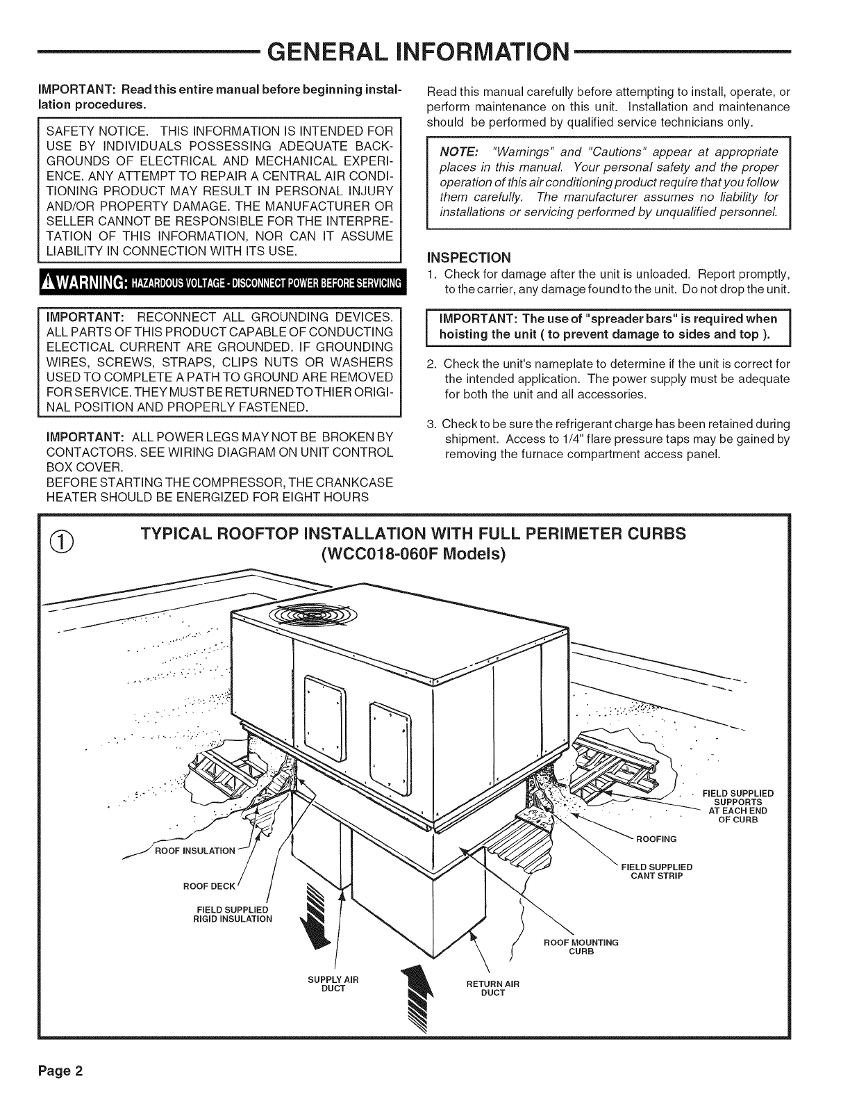
TYPICAL ROOFTOP INSTALLATION WITH FULL PERIMETER CURBS
(WCC018-060F Models)
~ • •FIELD SUPPLIED
SUPPORTS
AT EACH END
OFCURB
ROOF
FIELD SUPPLIED
RIGIDINSULATION
SUPPLY AIR
DUCT RETURN AIR
DUCT
ROOF MOUNTING
CURB
FIELD SUPPLiED
CANT STRIP
Page 2
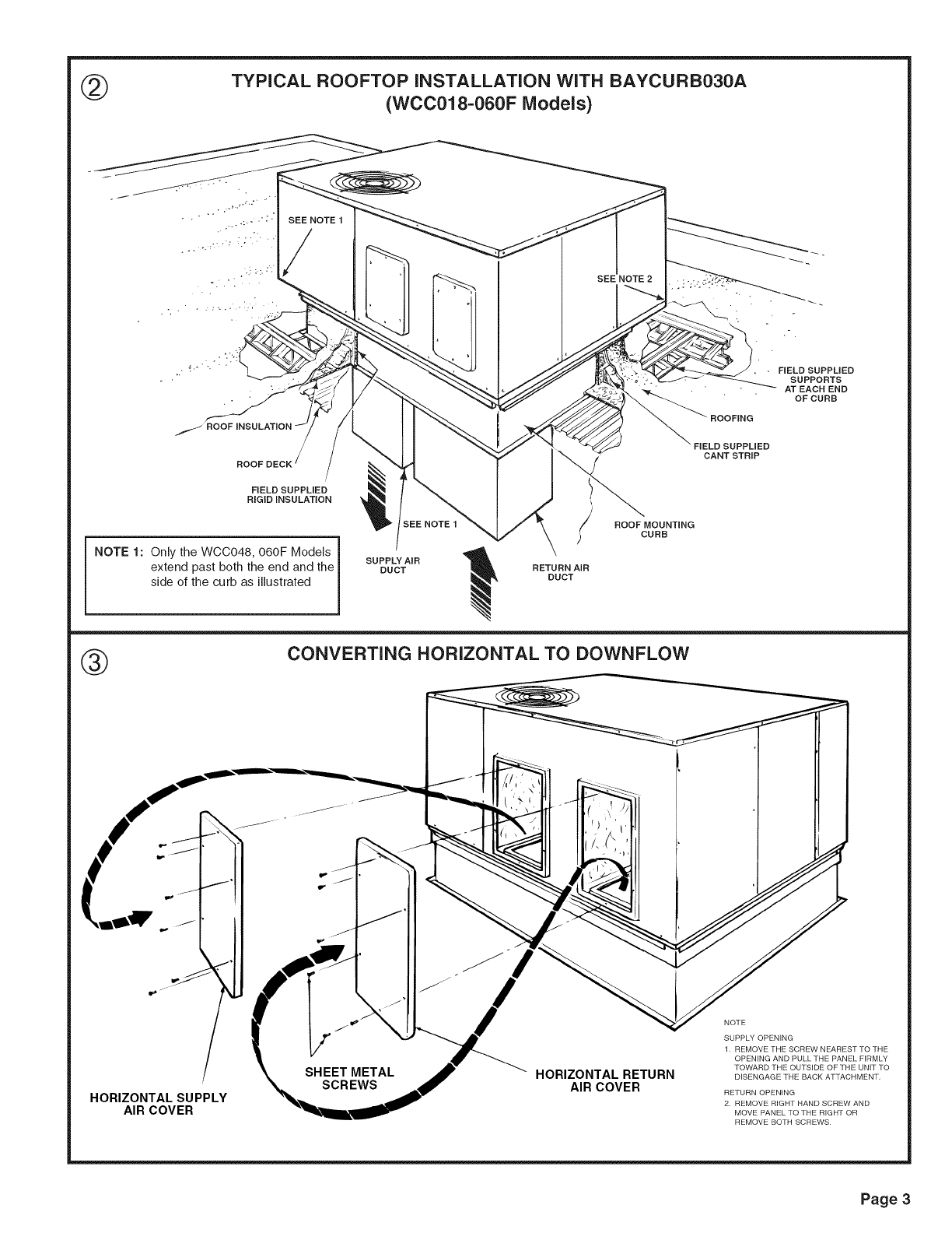
@TYPICAL ROOFTOP iNSTALLATiON WITH BAYCURB030A
(WCC018-060F Models)
SEE NOTE 1
SEE NOTE2
•FIELD SUPPLIED
SUPPORTS
AT EACH END
OFCURB
/ROOF
ROOF
FIELD SUPPLIED
RIGID iNSULATiON
NOTE 1: Only the WCC048, 060F Models
extend past both the end and the
side of the curb as illustrated
SEE NOTE 1
SUPPLY AiR
DUCT
ROOF MOUNTING
)CURB
RETURN AiR
DUCT
FIELD SUPPLIED
CANT STRIP
®CONVERTING HORIZONTAL TO DOWNFLOW
HORIZONTAL SUPPLY
AIR COVER
SHEET METAL
SCREWS HORIZONTAL RETURN
AIR COVER
NOTE
SUPPLY OPENING
1 REMOVE THE SCREW NEAREST TO THE
OPENING AND PULL THE PANEL FIRMLY
TOWARD THE OUTSIDE OF THE UNIT TO
DISENGAGE THE BACK ATTACHMENT,
RETURN OPENING
2 REMOVE RIGHT HAND SCREW AND
MOVE PANEL TO THE RIGHT OR
REMOVE BOTH SCREWS
Page 3
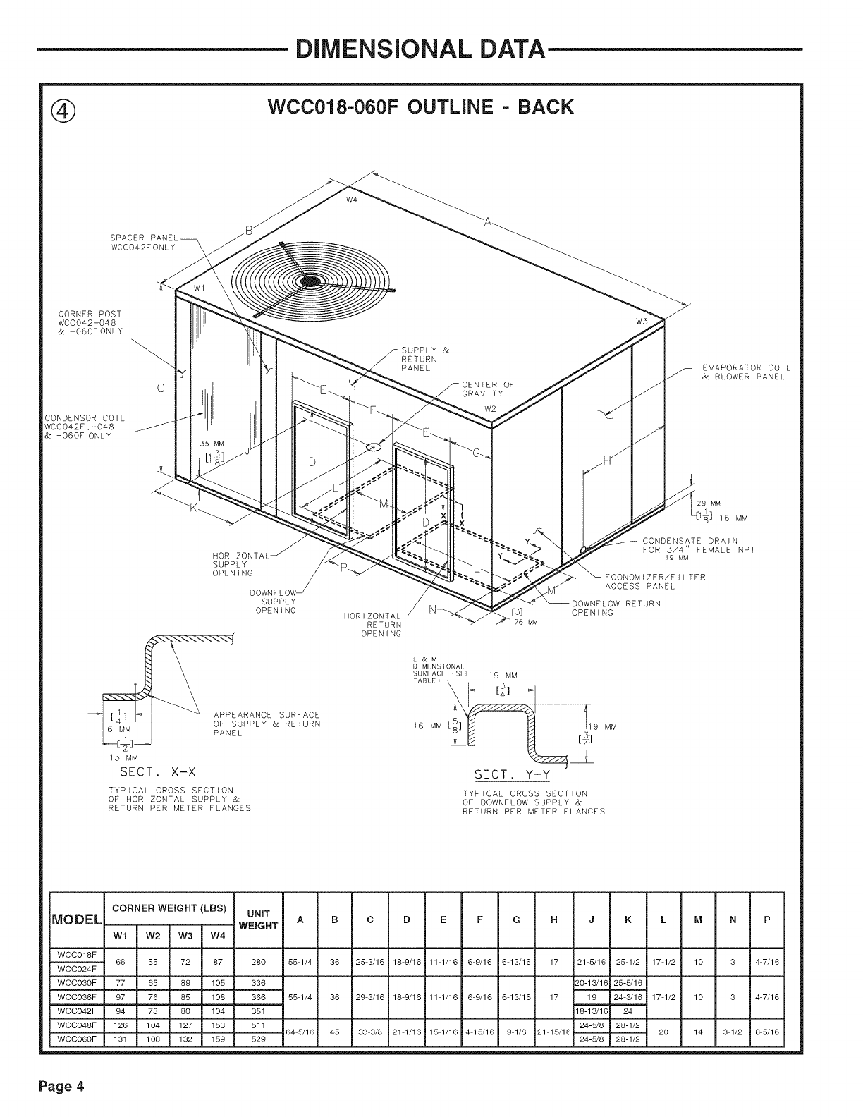
DiMENSiONAL DATA
WCC018-060F OUTLINE - BACK
_ _ L_ APPEARANCE SURFACE
OF SUPPLY & RETURN
6 MM PANEL
15 MM
SECT. X-X
OPENING
L &M
DIMENSIONAL
SURFACE (SEE 19 MM
16 MM -- M P 19 MM
SECT. Y-Y
TYPICAL CROSS SECTION
OF HORIZONTAL SUPPLY &
RETURN PERIMETER FLANGES
TYPICAL CROSS SECTION
OF DOWNFLOW SUPPLY &
RETURN PERIMETER FLANGES
MODEL CORNER WEIGHT (LRS) UNIT
WEIGHT
Wl W2 W3 W4
WCCO18F 66 55 72 87
WCCO24F
WCCO30F 77 65 89 105
WCCO36F 97 76 85 108
WCCO42F 94 73 80 104
WCCO48F 126 104 127 153
WCCO60F 131 108 132 159
280 55-1/4 36 25-3/16 18-9/16 11-1/16 6-9/16 6-13/16 17 21-5/16 25-1/2 17-1/2 10 3 4-7/16
336 20-13/1C 25-5/16
366 55-1/4 36 29-3/16 18-9/16 11-1/16 6-9/16 6-13/16 17 19 24-3/16 17-1/2 10 3 4-7/16
351 18-13/1¢ 24
511 24-5/8 28-1/2
64-5/16 45 33-3/8 21-1/16 15-1/16 4-15/16 9-1/8 21-15/16 20 14 3-1/2 8-5/16
529 24-5/8 28-1/2
Page 4
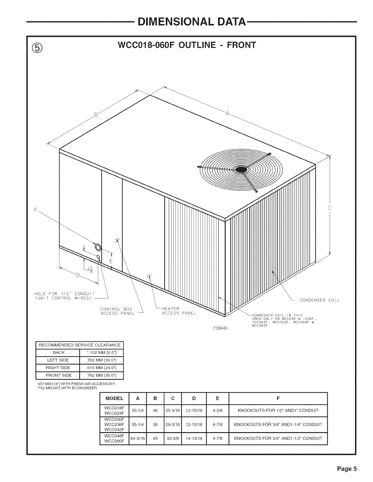
DiMENSiONAL DATA
WCC018-060F OUTLINE FRONT
HOLE FOR 1/2" CONDUIT
(UNIT CONTROL WIRES) --
CONTROL BOX HEATER
ACCESS PANEL ACCESS PANEL
729945
CONDENSER COIL
COIL ]N TH]S
AREA ONLY ON WCC050 & -056F,
TCC042F, WCC042F, WCCO48F &
WCCO6OF
RECOMMENDED SERVICE CLEARANCE
BACK * 152 MM [6.0"]
LEFT SIDE 762 MM [30.0"]
RIGHT SIDE 610 MM [24.0"]
FRONT SIDE 762 MM [30.0"]
•457 MM [18"] WITH FRESH AIR ACCESSORY
•762 MM [30"] WITH ECONOMIZER
MODEL
WCCO18F
WCCO24F
WCCO30F
WCCO36F
WCCO42F
WCCO48F
WCCO60F
A
55-1/4
55-1/4
64-5/16
B
36
36
45
C
25 3/16
29-3/16
33-3/8
D
12-1 _16
12-1 _16
14-1 _16
E
4-3/8
4-7/8
4-7/8
F
KNOCKOUTSFORI£"ANDI"CONDUIT
KNOCKOUTSFOR3_"ANDI-I_"CONDUIT
KNOCKOUTSFOR3_"ANDI-I£"CONDUIT
Page 5
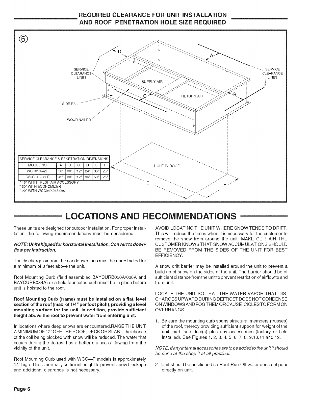
REQUIRED CLEARANCE FOR UNiT INSTALLATION
AND ROOF PENETRATION HOLE SiZE REQUIRED
®
SERVICE
CLEARANCE
LINES
-_. SERVICE
CLEARANCE
LINES
SIDE RAIL
J
J
WOOD NAILER _
SERVICE CLEARANCE & PENETRATION DIMENSIONS
MODEL NO. A B C D E F
WCC018-42F 30" 30" "12" 24" 36" 25"
WCC048-060F 42" 30" "12" 36" 50" 25"
* 18" WITH FRESH AIR ACCESSORY
* 30" WITH ECONOMIZER
* 20" WITH WCC042,048,060
HOLE IN ROOF
LOCATIONS AND RECOMMENDATIONS
These units are designed for outdoor installation. For proper instal-
lation, the following recommendations must be considered.
NOTE: Unit shipped for horizontal installation. Convert to down-
flow per instruction.
The discharge air from the condenser fans must be unrestricted for
a minimum of 3 feet above the unit.
Roof Mounting Curb (field assembled BAYCURB030A!038A and
BAYCURB034A) or a field fabricated curb must be in place before
unit is hoisted to the roof.
Roof Mounting Curb (frame) must be installed on a flat, level
section of the roof (max. of 1/4" per foot pitch), providing a level
mounting surface for the unit. In addition, provide sufficient
height above the roof to prevent water from entering unit.
In locations where deep snows are encountered,RAiSE THE UNIT
AMINIMUM OF 12" OFFTHE ROOF, DECKOR SLAB--the chance
of the coil being blocked with snow will be reduced. The water that
occurs during the defrost has a better chance of flowing from the
vicinity of the unit.
Roof Mounting Curb used with WCC--F models is approximately
14" high. This is normally sufficient height to prevent snow blockage
and additional clearance is not necessary.
AVOID LOCATING THE UNIT WHERE SNOWTENDS TO DRIFT.
This will reduce the times when it is necessary for the customer to
remove the snow from around the unit. MAKE CERTAIN THE
CUSTOMER KNOWS THAT SNOW ACCUMULATIONS SHOULD
BE REMOVED FROM THE SIDES OF THE UNIT FOR BEST
EFFICIENCY.
A snow drift barrier may be installed around the unit to prevent a
build up of snow on the sides of the unit. The barrier should be of
sufficient distance from the unitto prevent restriction of airflowto and
from unit.
LOCATE THE UNIT SO THAT THE WATER VAPOR THAT DIS-
CHARGES UPWARD DURING DEFROST DOES NOT CONDENSE
ON WINDOWS AN D FOG THEM OR CAUSE ICICLES TO FORM ON
OVERHANGS.
1. Be sure the mounting curb spans structural members (trusses)
of the roof, thereby providing sufficient support for weight of the
unit, curb and duct(s) plus any accessories (factory or field
installed). See Figures 1,2, 3, 4, 5, 6, 7, 8, 9,10,11 and 12.
NOTE: If any internal accessories are to be added to the unit it should
be done at the shop if at all practical.
2. Unit should be positioned so Roof-Run-Off water does not pour
directly on unit.
Page 6
3. For "Roof Top Application," unit must be elevated above roof with
a mounting Curb or Frame.
4. Exhaust vents or other sources of contaminated air should not
be near unit air inlet if outside air is to be introduced as a make-
up air or the economizer ventilation feature is to be used.
5. Check the handling facilities to insure the safety of personnel and
the unit(s).
6. CAUTION MUST BE TAKEN AT ALL TIMES TO AVOID PER-
SONAL INJURIES AND/OR DAMAGE TO EQUIPMENT.
7. The unit must be mounted level for proper drainage of defrost
water through the holes in the base pan.
8. Flexible duct connectors must be of a flame retardant material. All
duct work outside of the structure must be insulated and weath-
erproofed in accordance with local codes.
9. Roof flashing must be installed to seal the roof curb cavity and
must conform to local building codes.
10. Holes through exterior walls must be sealed in accordance with
local codes.
11. Access and service clearances for the unit must be given careful
consideration when locating the duct entrance openings. Fig-
ures 6 and 8 provide unit dimensions.
12. All fabricated outdoor ducts should be as short as possible.
13. Be sure the hole in the structure for the ducts is large enough to
accommodate the fabricated ducts and the insulation sur-
rounding them. (See Figure 6.)
CLEARANCES
1. The recommended clearances for single-unit installations are
illustrated in Figures 5 and 6. These minimum requirements are not
only an important consideration when determining unit placement,
but they are also essential to ensure adequate serviceability,
maximum capacity, and peak operating efficiency.
2. Any reduction of the unit clearances indicated in this illustration
may result in condenser coil starvation, or the recirculation of warm
condenser air. Actual clearances which appear to be inadequate
should be reviewed with a local sales engineer.
IMPORTANT!: To convert to downflow remove covers from
the downflow supply and return air openings and placethem
over the horizontal supply and return air openings (painted
side out) and secure with sheet metal screws.
iNSTALLATiON
UNIT SUPPORT
If unit is to be roof mounted, check building codes for weight
distribution requirements. Refer to accessory roof curb mounting
instructions. Check unit nameplate for supply voltage required.
Determine if adequate electrical power is available. Refer to speci-
fication sheet.
LOCATION AND CLEARANCES
Installation of the unit should conform to local building codes or, in
the absence of local codes, to the ANSI/NFPA No. 70-1987 National
Electrical Code or "Latest Revision." Canadian installations must
conform to CSA and local codes.
IMPORTANT!: DO NOT LIFT THE UNIT WITHOUT TEST-
LIFTING FOR BALANCE AND RIGGING.DO NOT LIFT THE
UNiT IN WINDY CONDITIONS OR ABOVE PERSONNEL. DO
NOT LiFT THE UNiT BY ATTACHING A CLEVIS, HOOKS,
PINS OR BOLTS TO THE UNiT CASING, CASING HARD-
WARE, ANGLES, TABS OR FLANGES. FAILURE TO OB=
SERVE THESE WARNINGS MAY RESULT IN EQUIPMENT
DAMAGE.
4. When the curb and air ducts have been properly installed, the unit
is ready to be hoisted to the roof and set in position.
I MPORTANT!: "Spreader Bars" must be used when
hoisting unit.
5. IMPORTANT: The unit must be lowered into position P.V.C.
rubber tape on the curb flange permits the unit to be
repositioned if required without destroying the P.V.C. rub=
bet seals affixed to mounting curb.
Select a location that will permit unobstructed airflow into the
condenser coil and away from the fan discharge and permit unob-
structed service access into the compressor compartment. Sug-
gested airflow clearances and service clearances are given in
Figure 5.
PLACING AND RIGGING
1. Before preparing the unit for lifting, check the outline drawing for
center of gravity for lifting safety. Because of placement of
internal components, the unit weight may be unevenly distrib-
uted. Approximate unit weights are given in outline drawing on
page 3.
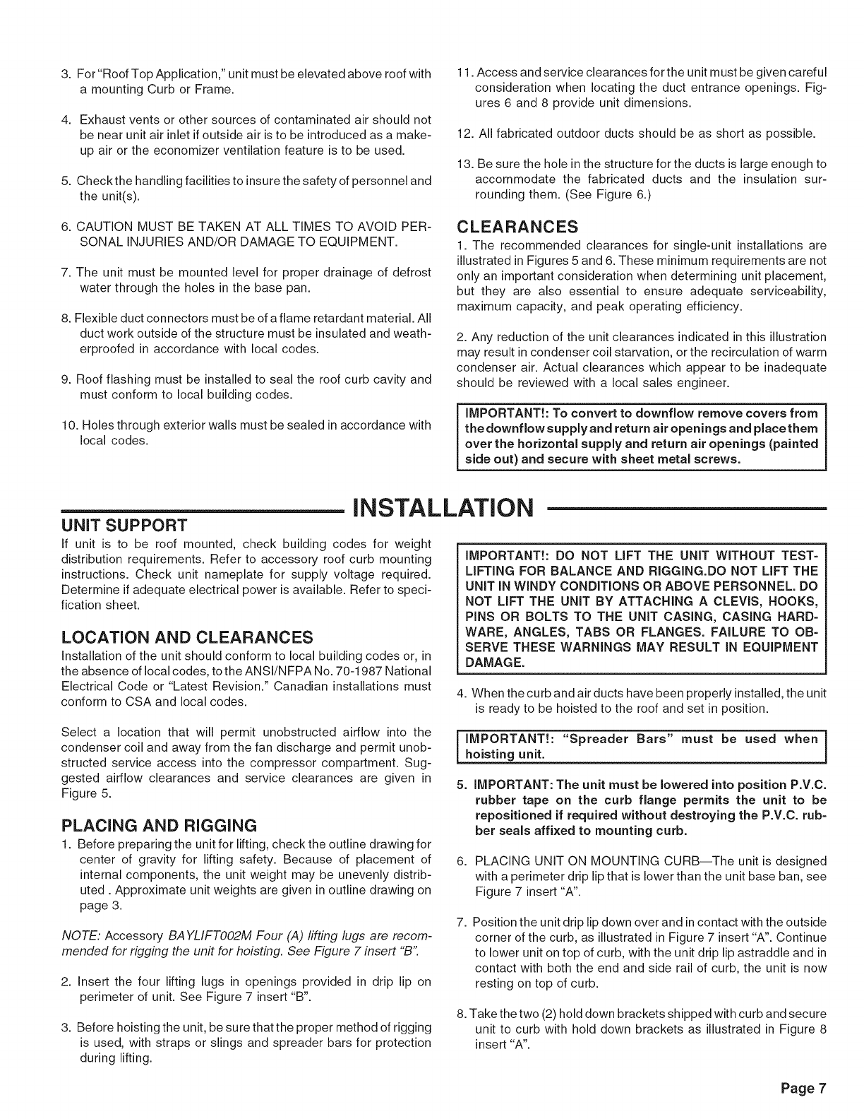
NOTE: Accessory BA YLIFTOO2M Four (,4) lifting lugs are recom-
mended for rigging the unit for hoisting. See Figure 7 insert "B"
2. Insert the four lifting lugs in openings provided in drip lip on
perimeter of unit. See Figure 7 insert "B".
3. Before hoisting the unit, be sure that the proper method of rigging
is used, with straps or slings and spreader bars for protection
during lifting.
6. PLACING UNIT ON MOUNTING CURB--The unit is designed
with a perimeter drip lip that is lower than the unit base ban, see
Figure 7 insert "A".
7. Position the unit drip lip down over and in contact with the outside
corner of the curb, as illustrated in Figure 7 insert "A". Continue
to lower unit on top of curb, with the unit drip lip astraddle and in
contact with both the end and side rail of curb, the unit is now
resting on top of curb.
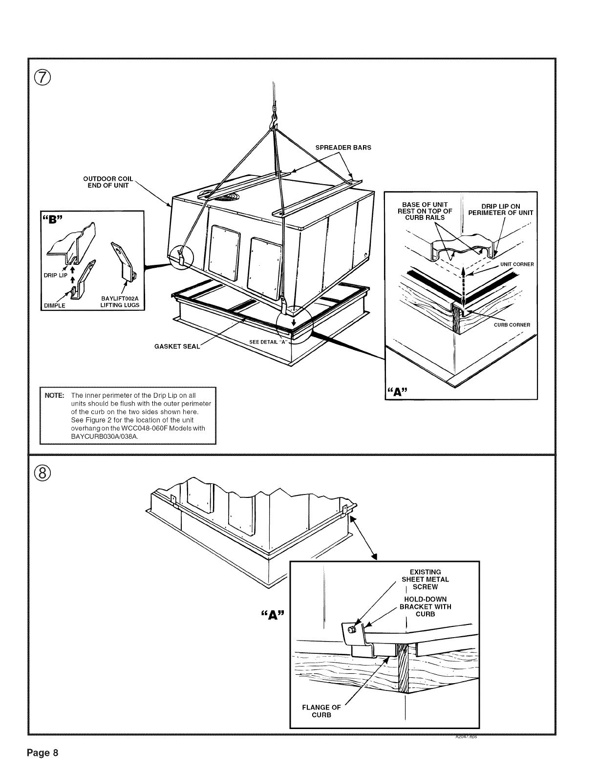
8. Take the two (2) hold down brackets shipped with curb and secure
unit to curb with hold down brackets as illustrated in Figure 8
insert "A".
Page 7
®
SPREADER BARS
OUTDOORCOIL
END OFUNIT
_)_ BAYLIFT002_A
DIMPLE LIFTING LUGS
GASKET SEAL'
NOTE: The inner perimeter of the Drip Lip on all
units should be flush with the outer perimeter
of the curb on the two sides shown here.
See Figure 2 for the location of the unit
overhang on the WCC048-060F Models with
BAYCURB030A/038A.
BASE OFUNIT
RESTONTOPOF
CURB RAILS
DRIP LIP ON
PERIMETER OF UNIT
!
CURB CORNER
J
®
Page 8
l;liA_lgl
FLANGE OF
CURB
EXISTING
SHEET METAL
I SCREW
HOLD-DOWN
BRACKET WITH
CURB
_u4/.eps
iNSTALLATiON
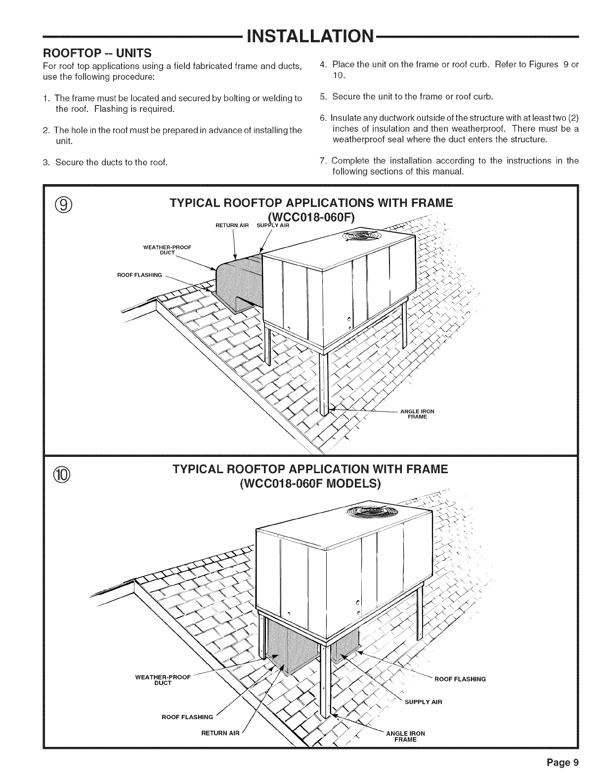
ROOFTOP -- UNITS
For roof top applications using a field fabricated frame and ducts, 4. Place the unit on the frame or roof curb. Refer to Figures 9 or
use the following procedure: 10.
1. The frame must be located and secured by bolting or welding to
the roof. Flashing is required.
2. The hole in the roof must be prepared in advance of installing the
unit.
5. Secure the unit to the frame or roof curb.
6. Insulate any ductwork outside of the structure with at least two (2)
inches of insulation and then weatherproof. There must be a
weatherproof seal where the duct enters the structure.
3. Secure the ducts to the roof. 7. Complete the installation according to the instructions in the
following sections of this manual.
®TYPICAL ROOFTOP APPLICATIONS WITH FRAME
lwccol8-060F)
RETURN AIR SUP 1 •
WEATHER-PROOF
DUCT
ROOF FLASHING
ANGLE IRON
/FRAME
@
/
TYPICAL ROOFTOP APPLICATION WITH FRAME
(WCC018-060F MODELS) /
DUCT
ROOF FLASHING
RETURN AIR
/
SUPPLY AIR
FRAME
FLASHING
Page 9
iNSTALLATiON
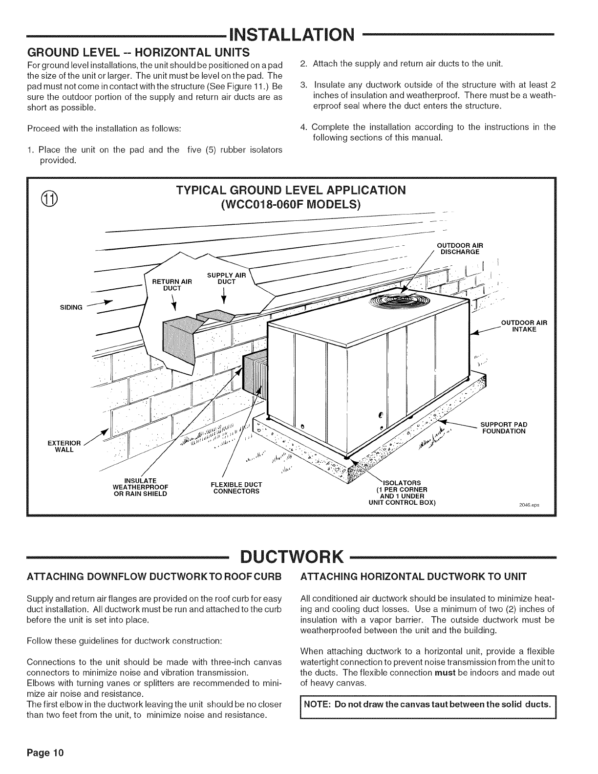
GROUND LEVEL -- HORIZONTAL UNITS
For ground level installations, the unit should be positioned on a pad
the size ofthe unit or larger. The unit must be level on the pad. The
pad must not come in contact with the structure (See Figure 11.) Be
sure the outdoor portion of the supply and return air ducts are as
short as possible.
2. Attach the supply and return air ducts to the unit.
3. Insulate any ductwork outside of the structure with at least 2
inches of insulation and weatherproof. There must be a weath-
erproof seal where the duct enters the structure.
Proceed with the installation as follows:
1. Place the unit on the pad and the five (5) rubber isolators
provided.
4. Complete the installation according to the instructions in the
following sections of this manual.
©TYPICAL GROUND LEVEL APPLICATION
(WCC018-060F MODELS)
SUPPLY AIR
RETURN AIR DUCT
DUCT
SIDING 1""_'I1_
OUTDOOR AIR
DISCHARGE
1
:t
! '
EXTERIOR
WALL
OUTDOOR AIR
INTAKE
SUPPORT PAD
FOUNDATION
INSULATE
WEATHERPROOF FLEXIBLE DUCT ISOLATORS
OR RAIN SHIELD CONNECTORS (1 PER CORNER
AND1 UNDER
UNITCONTROLBOX) 2046,eps
DUCTWORK
ATTACHING DOWNFLOW DUCTWORKTO ROOF CURB ATTACHING HORIZONTAL DUCTWORK TO UNIT
Supply and return air flanges are provided on the roof curb for easy
duct installation. All ductwork must be run and attached to the curb
before the unit is set into place.
Follow these guidelines for ductwork construction:
Connections to the unit should be made with three-inch canvas
connectors to minimize noise and vibration transmission.
Elbows with turning vanes or splitters are recommended to mini-
mize air noise and resistance.
The first elbow in the ductwork leaving the unit should be no closer
than two feet from the unit, to minimize noise and resistance.
All conditioned air ductwork should be insulated to minimize heat-
ing and cooling duct losses. Use a minimum of two (2) inches of
insulation with a vapor barrier. The outside ductwork must be
weatherproofed between the unit and the building.
When attaching ductwork to a horizontal unit, provide a flexible
watertight connection to prevent noise transmission from the unit to
the ducts. The flexible connection must be indoors and made out
of heavy canvas.
NOTE: Do not draw the canvas taut between the solid ducts, i
Page 10
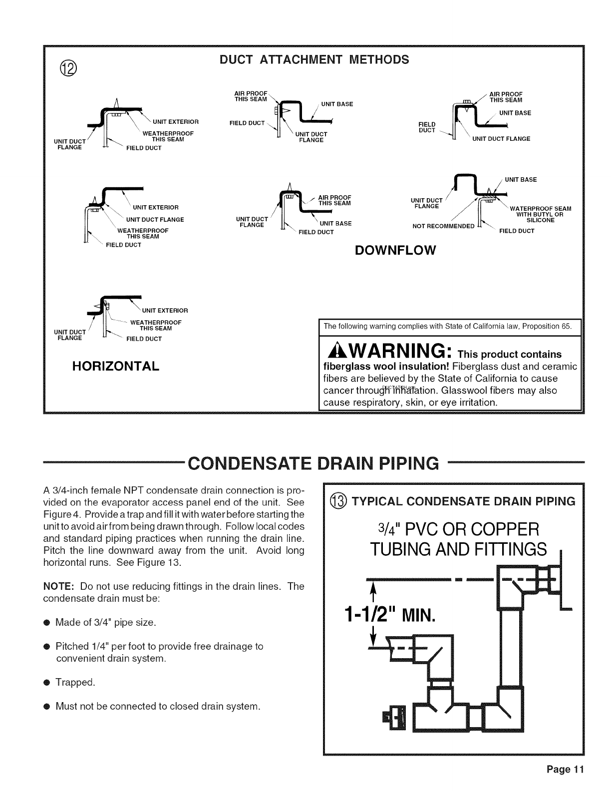
@DUCT ATTACHMENT METHODS
UNIT DUCT /I _'-_ THIS SEAM
FLANGE "_ " FIELD DUCT
AIR PROOF\
THIS SEAM
BASE
FIELD DUCTql X "_=======_
J.J "UNIT DUCT
FLANGE
AIR PROOF
3__ THIS SEAM
FIELDDucT_._ _ L_IT BASE
UNIT DUCT FLANGE
"FIELD DUCT
UNIT DUCT
FLANGE
PROOF
THIS SEAM UNIT DUCT
FLANGE
UNIT BASE
BASE NOT RECOMMENDED
FIELD DUCT FIELD DUCT
DOWNFLOW
SEAM
WITH BUTYL OR
SILICONE
'°R
UNIT DUCT
FLANGE FIELD DUCT
The following warning complies with State of California law, Proposition 65.
_:_WARNING: This product contains
HORIZONTAL fiberglass wool insulation! Fiberglass dust and ceramic
fibers are believed by the State of California to cause
cancer throug°Hfiff_ration. Glasswool fibers may also
cause respiratory, skin, or eye irritation.
CONDENSATE DRAIN PiPiNG
A 3/4-inch female NPT condensate drain connection is pro-
vided on the evaporator access panel end of the unit. See
Figure 4. Provide atrap and fill it with water before starting the
unit to avoid air from being drawn through. Follow local codes
and standard piping practices when running the drain line.
Pitch the line downward away from the unit. Avoid long
horizontal runs. See Figure 13.
NOTE: Do not use reducing fittings in the drain lines. The
condensate drain must be:
• Made of 3/4" pipe size.
• Pitched 1/4" per foot to provide free drainage to
convenient drain system.
• Trapped.
• Must not be connected to closed drain system.
@TYPICAL CONDENSATE DRAIN PiPiNG
3/4"PVC OR COPPER
TUBING AND FITTINGS
m
1-1/2"MIN.
Page 11
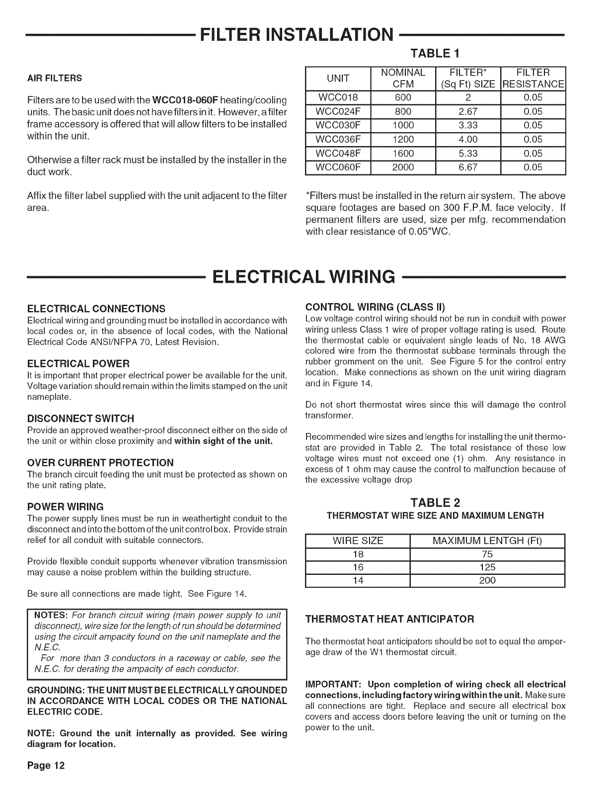
FILTER iNSTALLATiON
TABLE 1
AIR FILTERS
Filters are to be used with the WCC018-060F heating/cooling
units. The basic unit does not havefilters init. However, afilter
frame accessory isoffered that will allow filters to be installed
within the unit.
Otherwise a filter rack must be installed by the installer in the
duct work.
NOMINAL FILTER* FILTER
UNIT CFM (Sq Ft) SIZE RESISTANCE
WCC018 600 2 0.06
WCC024F 800 2.67 0.06
WCC030F 1000 3.33 0.06
WCC036F 1200 4.00 0.06
WCC048F 1600 6.33 0.06
WCC060F 2000 6.67 0.06
Affix the filter label supplied with the unit adjacent to the filter
area. *Filters must be installed in the return air system. The above
square footages are based on 300 F.P.M. face velocity. If
permanent filters are used, size per mfg. recommendation
with clear resistance of 0.05"WC.
ELECTRICAL WIRING
ELECTRICAL CONNECTIONS
Electrical wiring and grounding must be installed in accordance with
local codes or, in the absence of local codes, with the National
Electrical Code ANSI/NFPA 70, Latest Revision.
ELECTRICAL POWER
It is important that proper electrical power be available for the unit.
Voltage variation should remain within the limits stamped on the unit
nameplate.
DISCONNECT SWITCH
Provide an approved weather-proof disconnect either on the side of
the unit or within close proximity and within sight of the unit.
OVER CURRENT PROTECTION
The branch circuit feeding the unit must be protected as shown on
the unit rating plate.
POWER WiRiNG
The power supply lines must be run in weathertight conduit to the
disconnect and into the bottom of the unit control box. Provide strain
relief for all conduit with suitable connectors.
Provide flexible conduit supports whenever vibration transmission
may cause a noise problem within the building structure.
Be sure all connections are made tight. See Figure 14.
NOTES: For branch circu# wiring (main power supply to unit
disconnect), wire size for the length of run should be determined
using the circu# ampacity found on the unit nameplate and the
N.E.C.
For more than 3 conductors in a raceway or cable, see the
N.E.C. for derating the ampacity of each conductor.
GROUNDING: THE UNIT MUST BE ELECTRICALLY GROUNDED
IN ACCORDANCE WITH LOCAL CODES OR THE NATIONAL
ELECTRIC CODE.
NOTE: Ground the unit internally as provided. See wiring
diagram for location.
CONTROL WiRiNG (CLASS ll)
Low voltage control wiring should not be run in conduit with power
wiring unless Class 1 wire of proper voltage rating is used. Route
the thermostat cable or equivalent single leads of No. 18 AWG
colored wire from the thermostat subbase terminals through the
rubber gromment on the unit. See Figure 5 for the control entry
location. Make connections as shown on the unit wiring diagram
and in Figure 14.
Do not short thermostat wires since this will damage the control
transformer.
Recommended wire sizes and lengths for installing the unit thermo-
stat are provided in Table 2. The total resistance of these low
voltage wires must not exceed one (1) ohm. Any resistance in
excess of 1 ohm may cause the control to malfunction because of
the excessive voltage drop
TABLE 2
THERMOSTAT WIRE SIZE AND MAXIMUM LENGTH
WIRE SIZE MAXIMUM LENTGH (Ft)
18 75
16 125
14 200
THERMOSTAT HEAT ANTiCiPATOR
The thermostat heat anticipators should be set to equal the amper-
age draw of the W1 thermostat circuit.
IMPORTANT: Upon completion of wiring check all electrical
connections, including factory wiring within the unit. Make sure
all connections are tight. Replace and secure all electrical box
covers and access doors before leaving the unit or turning on the
power to the unit.
Page 12
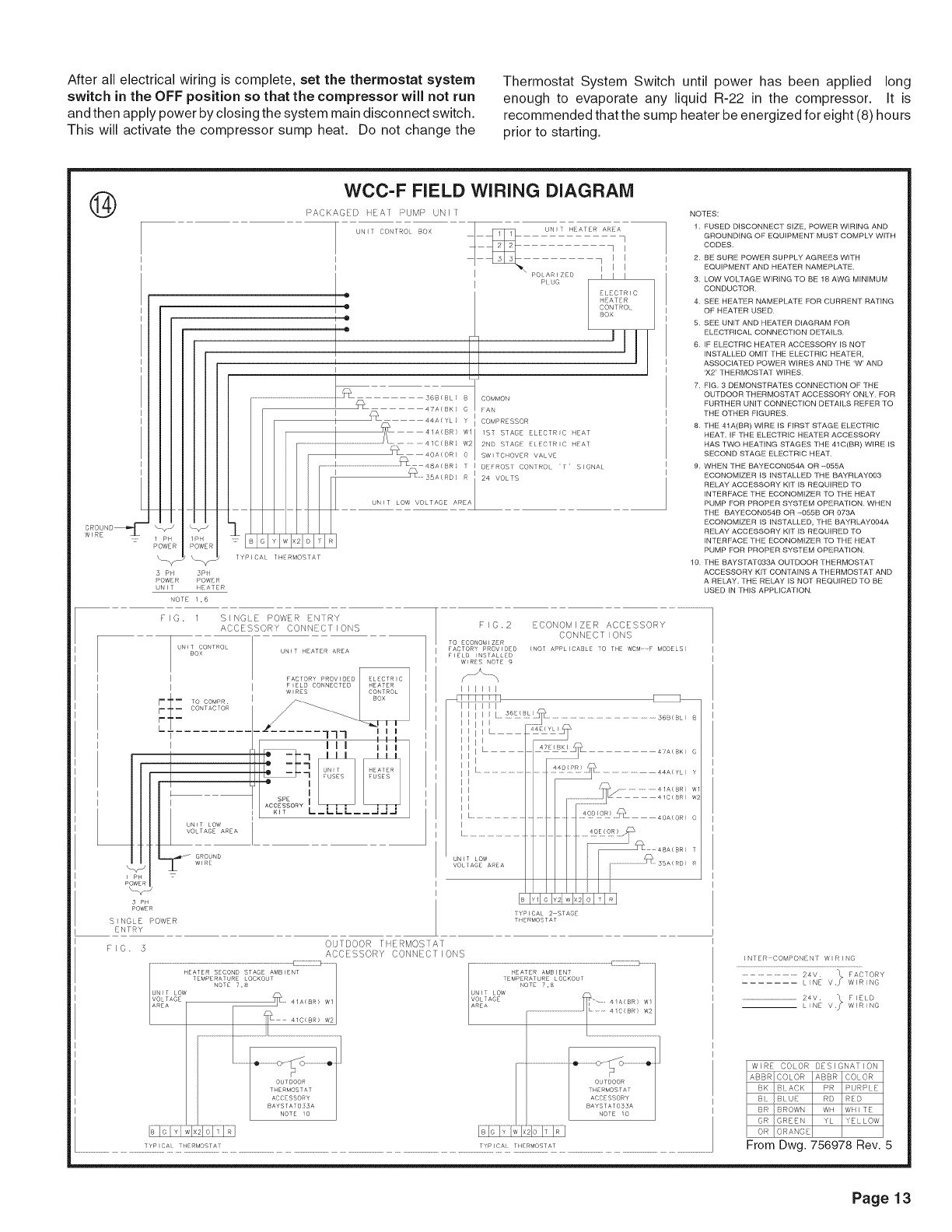
After all electrical wiring is complete, set the thermostat system
switch in the OFF position so that the compressor will not run
and then apply power by closing the system main disconnect switch.
This will activate the compressor sump heat. Do not change the
Thermostat System Switch until power has been applied long
enough to evaporate any liquid R-22 in the compressor. It is
recommended that the sump heater be energized for eight (8) hours
prior to starting.
@WCC-F FIELD WiRiNG DIAGRAM
Y
PH
ROWER
5 PI
POWER
UNIT
,s
H
_F
5Pt
POW R
HEATER
NOTE 1,6
PACKAGED qFAI RUM s UNI[
UN I (O IROI BOX
1
I
I
o
T •
I •
I
I
...........................................................................:++<+L>
/ _ 47AlSKl
IQ
U_ UN+T HALER AR ?
I I
1 I I
I I I
Pc AR I Z D I I I
PL UO
E CTRIC
H AT:R
CONTROL
BOX
B COMMON
G FAN
I i-x 44A(YI / I COMPR SSOR
I _ 41A(BR) Wll 1ST STAGE ELECTRC qEAT
i
...................................................................................... 41C(BR} W2 2N} SlAG El CIR C H A1
I _ 55A(RD} R 24 VO TS
//
I: UNIT LOW VOLTAGE AREA_
+IG. 1 SINGE POWER EN[RY
ACCF SSORY CONN/:C[ I ONS
UNIT CONTROL
80X
I
I
it:............
CONTACTOR
_Z
I
,
bN T LOW
VOLTAGE AREA
.,,,_ _ GROUND
WIRE
177 I I I
POWER
S NGLE POWER
ENTRY
FIG. 5
F}O.2 ECONOMIZER ACCESSORY
CONNECTIONS
TO ECONOMIZER
FACTORY PROV+DE© (NOT APPLICABLE TO THE WCM-F MODELS_
FIELD +NSTAILED
W_RES NOTE 9
III1_1
I1+1
I I I c_ f{_[_!_ .............................................................. sGB B+ +3
i I ............I
• 44 Y }
i I _
I • _SL +XA{BK_ C
1........................................!£ I!} /J\......................44A(Y )
/_ .....................41A(BR)
W2
..................................... _!)!_)R! _L 40A(OR) 0
40E(OR)
NIT LOW .....
........ 5A(I_D) R
VO AG[ A_,+: A
hi+ q+l_qol:l_l
?YP CAI 2 STAC_
THERMOSTAT
Ok#DOOR +:RMOS AT
ACC:SSO::(Y CONN::C IONS
OU DO01:I
3H RMOSTA
ACCESSORY
BAYS :A :055A
NOTE 0
IYP CA I I[RMOSTA? TYP CA TII RMOS]AT
NOTES:
1 FUSED DISCONNECT SIZE, POWER WIRING AND
GROUNDING OF EQUIPMENT MUST COMPLY WITH
CODES
2 BE SURE POWER SUPPLY AGREES WITH
EQUIPMENT AND HEATER NAMEPLATE
3 LOW VOLTAGE WIRING TO BE 18 AWG MINIMUM
CONDUCTOR
4 SEE HEATER NAMEPLATE FOR CURRENT RATING
OF HEATER USED
5 SEE UNIT AND HEATER DIAGRAM FOR
ELECTRICAL CONNECTION DETAILS
6 IF ELECTRIC HEATER ACCESSORY IS NOT
INSTALLED OMIT THE ELECTRIC HEATER,
ASSOCIATED POWER WIRES AND THE 'W' AND
'X2' THERMOSTAT WIRES
7 FIG, 3 DEMONSTRATES CONNECTION OF THE
OUTDOOR THERMOSTAT ACCESSORY ONLY FOR
FURTHER UNIT CONNECTION DETAILS REFER TO
THE OTHER FIGURES
8 THE 41A(BR) WIRE IS FIRST STAGE ELECTRIC
HEAT, IF THE ELECTRIC HEATER ACCESSORY
HAS TWO HEATING STAGES THE 41C(BR) WIRE IS
SECOND STAGE ELECTRIC HEAT
9 WHEN THE BAYECON054A OR 055A
ECONOMIZER IS INSTALLED THE BAYRLAY003
RELAY ACCESSORY KIT IS REQUIRED TO
INTERFACE THE ECONOMIZER TO THE HEAT
PUMP FOR PROPER SYSTEM OPERATION WHEN
THE BAYECON054B OR 055B OR 073A
ECONOMIZER IS INSTALLED, THE BAYRLAY004A
RELAY ACCESSORY KIT IS REQUIRED TO
INTERFACE THE ECONOMIZER TO THE HEAT
PUMP FOR PROPER SYSTEM OPERATION
10 THE BAYSTAT033A OUTDOOR THERMOSTAT
ACCESSORY KIT CONTAINS A THERMOSTAT AND
A RELAY, THE RELAY IS NOT REQUIRED TO BE
USED IN THIS APPLICATION
INTER COMPONENI W}RINO
......................... 24V _ FACTORY
L}NE V.J WIR+NO
.......................................................................24V _ FIEID
LiNE V _ WIR+NO
WIRE COLOR DESIGNATION
ABBRICOLOR ABBR COLOR
BK }B}ACK PR RURP}E
} Bt }8tLJEI RD REID
BR IBROWN WH WHITE
OR IGREEN YL YELLOW
OR IORANCE
From Dwg. 756978 Rev. 5
Page 13
START-. UP
PRE-START QUICK CHECKLIST
•Is the unit properly located and level with the proper clearance?
See Figure 5.
• Is the duct work correctly sized, run, taped, insulated, and
weatherproofed with proper unit arrangement. See Ductwork
Installation section.
• Is the condensate line properly sized, run, trapped, and pitched?
• Is the filter of the correct size and number? Is it clean and in place?
• Is the wiring properly sized and run according to the unit wiring
diagram?
• Are all the wiring connections, including those in the unit, tight?
• Has the unit been properly grounded and fused with the recom-
mended fuse size? See Wiring Data.
• Is the thermostat level, correctly wired, well located, and set for the
proper heat anticipation?
• Have the air conditioning systems been checked at the service
ports for charge and leak tested if necessary?
To start the unit in the cooling mode, set the thermostat system
switch to COOL and move the thermostat COOL indicator to a
setting below room temperature. The condenser (outdoor) fan
motor compressor and evaporator (indoor) fan motor will operate
automatically.
OPERATING PRESSURES
After the unit has operated in the cooling mode for a short period of
time, install pressure gauges on the gauge ports of the discharge
and suction line valves. Check the suction and discharge pressures
and compare them to the normal operating pressures provided in
the unit's SERVICE FACTS.
NOTE: Do not use the pressures from the unit's SERVICE FACTS
to determine the unit refrigerant charge. The correct charge is
shown on the unit nameplate. To charge the system accurately,
weigh in tlhe charge according to the unit nameplate.
VO LTAG E
With the compressor operating, check the line voltage at the unit.
The voltage should be within the range shown on the unit name-
plate. If Iowvoltage is encountered, check the size and length of the
supply line from the main disconnect to the unit. The line may be
undersized for the length of the run.
•Do the condenser fan and indoor blower turn free without rubbing,
and are they tight on the shafts?
•Has the indoor blower speed been determined and the proper
speed been set? See the Unit Wiring Diagram.
• Has all work been done in accordance with applicable local and
national codes?
• Are all covers and access panels in place to prevent air loss and
safety hazards?
STARTING THE UNIT iN THE COOLING MODE
CAUTION: Before startingthe system on the cooling cycle, turn the
thermostat switch to OFF and close the unit disconnect switch. This
procedure energizes the compressor crankcase heater, vaporizing
any liquid refrigerant in the crankcase. This is a precaution against
foaming at startup which could damage the compressor bearings.
Allow the heater to operate a minimum of eight (8) hours.
NOTE: See the section on "Sequence of Operation" for a descrip-
tion of the cooling operating sequence.
COOLING SHUT DOWN
Place the system selector in the OFF position or reset thermostat at
a setting above room temperature.
Do not de-energize the main power disconnect except when unit it
to be serviced. Power is required to keep the heat pump compres-
sor warm and boil off refrigerant in the compressor.
STARTING THE UNIT iN THE HEATING MODE
NOTE: See the section on "Sequence of Operation" for a descrip-
tion of the heat pump heating operating sequence.
Check to make sure all grilles an registers are open an all unit
access doors are closed before start-up.
Slowly set the thermostat above tom temperature until achieving a
first stage call for heat and place the fan switch in the AUTO or ON
position.
HEATING SHUT-DOWN
Place the system selector switch at OFF or place the heating
selector lever at a setting below room temperature.
WARNING: DONOTOPERATETHEUNIT
WITHOUT THE EVAPORATOR FAN ACCESS PANEL IN
PLACE. REINSTALL THE ACCESS PANEL AFTER
PERFORMING ANY MAINTENANCE PROCEDURES ON THE
FAN. OPERATING THE UNIT WITHOUT THE ACCESS
PANEL PROPERLY INSTALLED MAY RESULT IN SEVERE
PERSONAL INJURY OR DEATH.
Page 14
SEQUENCE OF OPERATION
Heat Pump -- General
Operation of the unit heating and cooling cycles is automatic when
the system is in the HEAT or COOL functions. (The optional
automatic changeover thermostat, when in the AUTO position,
automatically changes to heat or cool with an appropriate room
temperature change.) The fan switch can be placed in the ON
position, causing continuous indoor fan operation. The fan switch
may also be placed in the AUTO position causing fan operation to
coincide with heating or cooling run cycles.
Cooling Mode
With the disconnect in the ON position, current is supplied to the
sump heater and control transformer. The sump heater supplies
heat to the compressor to prevent liquid refrigerant from accumulat-
ing in the compressor during the off cycle.
The thermostat temperature switch (TSC-1) closes completing the
24 volt circuit from terminal "R" to terminal "O" energizing the
switchover valve solenoid coil (SC). (Nothing else occurs.)
Second Stage Cooling (after a 0.7°Fto 1.5°F temperature rise): The
thermostat temperature switch (TSC=2) closes completing the 24
volt circuit from terminal "R" to terminal "Y" energizing the compres-
sor contactor (MS) and to terminal "G" to energize the fan relay (F).
The MS-1 and MS-2 contacts close simultaneously energizing the
compressor,and outdoor fan motor. The F=I contact closes and
energizes the indoor fan motor. When the (TSC=2) switch closes, the
cooling anticipator is bypassed.
Heating Mode
The thermostat heating switch (TSH=I) closes completing the 24 volt
circuit from terminal "R" to terminal "Y" energizing the compressor
contactor and to terminal "G" to energize the fan relay (F). When
(TSH-1) closes, the heat anticipator (HA)is energized. (The heat
anticipator provides heat to the thermostat bimetal during operation
of the heat pump or resistance heat cycle. The switchover valve (SO)
is not energized due to the voltage drop across the heat anticipator.)
The MS-1 and MS=2 contacts close simultaneously and energize the
compressor,and the outdoor fan motor. At the same time, the F=I
contacts close and energize the indoor fan motor and the F=2
contacts provide a fan interlock for the heater control circuit
Second Stage Heating (after a 0.7°F to 1.5° F temperature drop):
The thermostat heating switch TSH-2 closes and completes a 24 volt
circuit from terminal "R" to terminals "W" and "U" which are bussed
together and thereby energizes the blue light on the thermostat.
Emergency Heat
Positioning the emergency resistance heat switch (RHS) in the
thermostat to the ON position will de-energize the refrigerant system
and the supplementary heat will come on through the second stage
heating contact (TSH-2) of the thermostat. Prior to this, the first
stage heating contact (TSH-1) would have closed the circuit to the
indoor blower, which will continue to run through the emergency heat
cycle and will stop when TSH-1 is satisfied and opens. A red light
indicator is visible when the switch is set to emergency heat.
Electronic Time and Temperature Defrost
Defrost Cycle
The electronic defrost board is a combination time/temperature
device. It is designed to control the removal of frost and ice from the
outdoor coil of a heat pump when coil temperatures are low.
Defrosting of the coil is initiated at a pre-selected time interval,
provided the outdoor coil is below the preset initiation temperature.
One of three time intervals (50, 70, or 90 minutes) may be chosen,
allowing the installer to adjust the time for his particular climate. In
humid and northern climates, for example, the time interval may
need to be shorter than in dry climates.
The electronic defrost board terminates the defrosting cycle when
the outdoor coil temperature rises to the preset termination tem-
perature or after a preset defrost time has passed, regardless of
windvelocity. This helps ensurethatthe heat pump stays in defrost
only as long as is necessary to remove the frost and ice from the
outdoor coil.
OPERATION: Power to the defrost board (DFC) is provided when
the temperature sensing switch (DT) on the outdoor coil is closed.
Defrost time interval is accumulated with starts and stops of the wall
thermostat's call for heating. At the end of the chosen time interval,
assuming the temperature sensing switch is closed, a defrost cycle
starts. When the defrost cycle starts, the contacts on the defrost
board close thereby energizing the switchover valve relay (SOV)
and the electric heater contactor. A normally closed contact on the
defrost board opens the circuit to the outdoor fan motor (ODM).
The defrost cycle is terminated when the temperature sensing
switch opens or the 10 minute override interrupts the defrost period.
On termination of the defrost cycle, the timing period is reset.
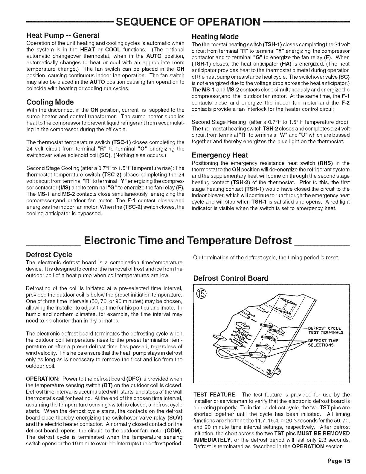
Defrost Control Board
®
SELECTIONS
TEST FEATURE: The test feature is provided for use by the
installer or serviceman to verify that the electronic defrost board is
operating properly. To initiate a defrost cycle, the two TST pins are
shorted together until the cycle has been initiated. All timing
functions are shortened to 11.7, 16.4, or 20.3 seconds for the 50, 70,
and 90 minute time interval settings, respectively. After defrost
initiation, the short across the two TST pins MUST BE REMOVED
IMMEDIATELY, or the defrost period will last only 2.3 seconds.
Defrost is terminated as described in the OPERATION section.
Page15
FINAL iNSTALLATiON CHECKLIST
• Does the unit run and operate as described in the section on
"Sequence of Operation" in response to the room thermostat?
• Are the condenser fan and indoor flower operating correctly with
proper rotation and without undue noise?
• Is the compressor operating correctly and has the system been
checked with a charging chart?
• Has the voltage and running current been checked to determine
if it is within limits?
• Has the thermostat been checked for calibration and the air
discharge grilles adjusted to balance the system?
• Has the ductwork been checked for air leaks and condensation?
• Has the furnace manifold pressure been checked and adjusted if
necessary?
• Has the heating air temperature rise been checked?
• Has the unit been checked for tubing and sheet metal rattles? Are
there any other unusual noises to be checked?
• Are all covers and panels in place and properly fastened?
• Has the owner or maintenance personnel been given this manual
and the warranty? Has the owner or maintenance been instructed
on proper operation and maintenance of this unit?
Page 16
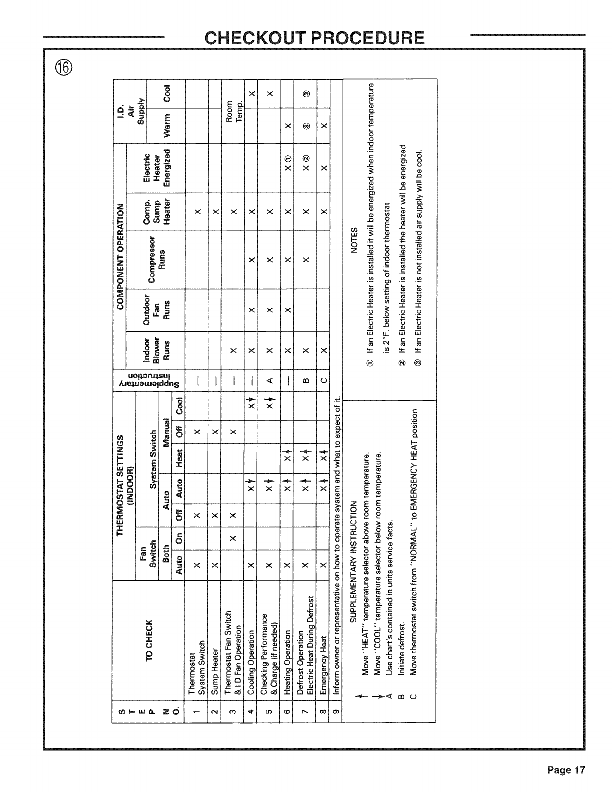
CHECKOUT PROCEDURE
®
w
Io,._
ZI _--=
__l E =;
0 _0
0 _
uop._ruJ.sul
/u_ueu, Jeiddn S
8
°g
_ C
0
0-_ =--
:E < g
W
<
M,I
_w_ zd
x
t
x
m
X
x
r.*
o
k.-O_
cd
OE
o_
X x
x
x X
X X
x
x
q3 _C:
"I" 0
x x
X x
X X
x x
X X
J<
x x
x x
x x
o
0
÷i
xi x
i
x i x
xIx
×i
X X
x X
X X
x X
0
c c._c
0 0 _"
o_
O
x
O
J=
¢=
E
o}
o
o
O
o_
E
O
c
03
C_
E
O
3°_ _=
"_ _ 0
c "8 c c
._- o_ .-_ .-_
LM LL LLI LU
® @ @
.o
0
O_ Z
E E
8 o
._ o
_'_ _ E
Page 17
MAINTENANCE
ROUTINE MAINTENANCE BY OWNER
You can do some of the periodic maintenance functions for
your WCC-F unit yourself; this includes replacing the dispos-
able or cleaning the permanent air filters, cleaning the unit
cabinet, clearing the condenser coil, and conducting a general
unit inspection on a regular basis.
Be su re to inspect them at least once each month when the
system is in constant operation. (In new homes, check the
filters every week for the first four (4) weeks.)
MAINTENANCE PERFORMED BY SERVICEMAN==
HEATING SEASON
Complete the unit inspections and service routines described
below at the beginning of each heating season.
• Visually inspect the unit to ensure that the airflow required for
condenser coil is not obstructed from the unit.
• Inspect the control panel wiring to verify that all electrical
connections are tight and that the wire insulation is intact.
If you have disposable-type filters, replace them with new
filters of the same type and size. Do not attempt to clean
disposable filters.
Permanent-type filters can be cleaned by washing them with a
mild detergent and water. Make sure that the filters are
thoroughly dry before re-installing them in the unit (or duct
system).
NOTE: It may be necessary to replace permanent filters
annually if washing fails to clean the filter or if the filter shows
signs of deterioration. Be sure to use the same type and size
as was originally installed.
CONDENSER COIL
Unfiltered air circulates through the unit's condenser coil and
can cause the coil's surface to become clogged with dust, dirt,
etc. To clean the coil, vertically (i.e., with the fins) stroke the
coil surface with a soft-bristled brush.
Be sure to keep all vegetation away from the condenser coil
area.
MAINTENANCE PERFORMED BY SERVICEMAN==
COOLING SEASON
To keep your unit operating safely and efficiently, the manufac-
turer recommends that a qualified serviceman checkthe entire
system at least once each year and any other time that you feel
one is needed. Your serviceman should examine these areas
of your WCC-F unit:
• filters (for cleaning or replacement)
• motors and drive system components
• gaskets (for possible replacement)
• safety controls (for mechanical cleaning)
• electrical components and wiring (for possible replacement and
connection tightness)
• condensate drain (for cleaning)
• unit duct connections (to see that they are physically sound and
sealed to the unit casing)
• unit mounting support (for structural integrity)
WARNING: TO PREVENT INJURY OR DEATH
DUE TO ELECTRICAL SHOCK OR CONTACT WITH MOVING
PARTS. LOCK UNIT DISCONNECT SWITCH IN OPEN
POSITION BEFORE SERVICING UNIT.
WARNING: TO PREVENT AN EXPLOSION I
OR POSSIBLE INJURY, DEATH AND EQUIPMENT DAMAGE, I
DO NOT STORE COMBUSTIBLE MATERIALS, GASOLINE I
OR OTHER FLAMMABLE VAPORS OR LIQUIDS NEAR THE I
UNIT. J
The following warning complies with State of California law, Proposition 65.
WARNING: This product contains
fiberglass wool insulation! Fiberglass dust and ceramic
fibers are believed by the State of California to cause
cancer through inhalation. Glasswool fibers may also
cause respiratory, skin, or eye irritation.
PRECAUTIONARY MEASURES
•Avoid breathing fiberglass dust.
• Use a NIOSH approved dust/mist respirator.
• Avoid contact with the skin or eyes. Wear long-
sleeved, loose-fitting clothing, gloves, and eye
protection.
• Wash clothes separately from other clothing: rinse
washer thoroughly.
Operations such as sawing, blowing, tear-out, and
spraying may generate fiber concentrations requiring
additional respiratory protection. Use the appropriate
NIOSH approved respirator in these situations.
FIRST AID MEASURES
Eye Contact - Flush eyes with water to remove dust.
If symptoms persist, seek medical
attention.
Skin Contact Wash affected areas gently with soap
and warm water after handling.
A150988P01
• the unit (for obvious unit deterioration)
Page 18
Limited Warranty
Heat Pump
WCC, WCD, WCH,
WCM and WSC (Parts ©nly)
Models Less Than 20 Tons for ResidentiaJ Use*
This limited warranty is extended by American Standard inc., to the original purchaser and to any succeeding owner of
the real property to which the Heat Pump is originally affixed, and applies to products purchased and retained for use
within the U.S.A. and Canada.
If any part of your Heat Pump fails because of a manufacturing defect within five years from the date of the original
purchase, Warrantor will furnish without charge the required replacement part. Any local transportation, related service
labor, diagnosis calls, refrigerant and related items are not included.
If the sealed motor-compressor fails because of a manufacturing defect within five years from the date of original
purchase, Warrantor will furnish without charge the required replacement compressor. Any local transportation, related
service labor, diagnosis calls, refrigerant and related items are not included.
This limited warranty does not cover failure of your Heat Pump if it is damaged while in your possession, failure
attributable or caused by unreasonable use of the Heat Pump and/or failure to properly maintain the Heat Pump as set
forth in the Use and Care manual.
This limited warranty applies to product installed on or after 10/1/2001 where product is manufactured after 1/1/2000.
This limited warranty is not retroactive to any installations prior to 10/1/2001 or on product produced prior to 2000.
THE LIMITED WARRANTY AND LIABILITY SET FORTH HEREIN ARE IN LIEU OF ALL OTHER
WARRANTIES AND LIABILITIES, WHETHER IN CONTRACT OR IN NEGLIGENCE, EXPRESS OR
IMPLIED, IN LAW OR IN FACT, INCLUDING IMPLIED WARRANTIES OF MERCHANTABILITY AND
FITNESS FOR PARTICULAR USE, AND IN NO EVENT SHALL WARRANTOR BE LIABLE FOR ANY
INCIDENTAL OR CONSEQUENTIAL DAMAGES.
Some states do not allow limitations on how long an implied limited warranty lasts or do not allow the exclusion or
limitation of incidental or consequential damages, so the above limitation or exclusion may not apply to you. This
limited warranty gives you specific JegaJ rights, and you may also have other rights which vary from state to state.
Parts will be provided by our factory organization through an authorized service organization in your area listed in the
yellow pages. If you wish further help or information concerning this limited warranty, contact:
American Standard Inc.
Troup Highway
Tyler, TX 75711-9010
Attention: Manager, After Sales Support
GW-611-4001
* This limited warranty is for residential usage of this equipment and not applicable when this equipment is used for a
commercial application. A commercial use is any application where the end purchaser uses the product for other than
personal, family or household purposes.
Page19
LiMiTED WARRANTY
HiGH EFFiCiENCY HEAT PUMP
WCZ, WCY, WCX, WCC, WCD, WCH, WCM and WSC
Models Less Than 20 Tons for Commercial Use*
(Parts Only)
This warranty is extended by American Standard Inc., to the original purchaser and to any
succeeding owner of the real property to which the Heat Pump is originally affixed, and applies to
products purchased and retained for use within the U.S.A. and Canada. There is no warranty
against corrosion, erosion or deterioration.
If any part of your Heat Pump fails because of a manufacturing defect within one year from the date
of the original purchase, Warrantor will furnish without charge the required replacement part.
In addition, if the sealed motor-compressor fails because of a manufacturing defect within the
second through fifth year from the date of original purchase, Warrantor will furnish without charge
the required replacement compressor. Warrantor's obligations and liabilities under this warranty
are limited to furnishing F.O.B. Warrantor factory or warehouse replacement parts for Warrantor's
products covered under this warranty. Warrantor shall not be obligated to pay for the cost of lost
refrigerant. No liability shall attach to Warrantor until products have been paid for and then liability
shall be limited solely to the purchase price of the equipment under warranty shown to be
defective.
THE WARRANTY AND LIABILITY SET FORTH HEREIN ARE IN LIEU OF ALL
OTHER WARRANTIES AND LIABILITIES, WHETHER IN CONTRACT OR IN
NEGLIGENCE, EXPRESS OR IMPLIED, IN LAW OR IN FACT, INCLUDING
IMPLIED WARRANTIES OF MERCHANTABILITY AND FITNESS FOR
PARTICULAR USE, AND IN NO EVENT SHALL WARRANTOR BE LIABLE
FOR ANY INCIDENTAL OR CONSEQUENTIAL DAMAGES.
Some states do not allow limitations on how long an implied warranty lasts or do not allow the
exclusion or limitation of incidental or consequential damages, so the above limitation or exclusion
may not apply to you. This warranty gives you specific legal rights, and you may also have other
rights which vary from state to state.
American Standard Inc.
Troup Highway
Tyler, TX 75711-9010
Attention: Manager, After Sales Support
GW-604-4800
* This warranty is for commercial usage of said equipment and not applicable when the equipment
is used for a residential application. Commercial use is any application where the end purchaser
uses the product for other than personal, family or household purposes.
Since American-Standard has a policy of continuous product and
product data improvement, it reserves the right to change design and
specification without notice.
American-Standard Inc.
6200 Troup Highway
Tyler,TX 75703 0( )0sTechnical Literature - Printed in U.S.A.
Page 20
