TRENDNET TEW421PC 802.11G WLAN CARD BUS ADAPTER User Manual WLG 1101 Manual
TRENDNET, INC. 802.11G WLAN CARD BUS ADAPTER WLG 1101 Manual
UserManual.wiki
>
TRENDNET
>
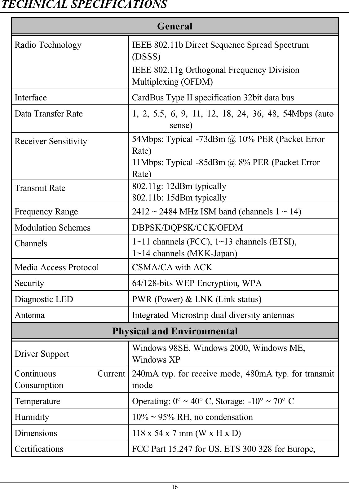
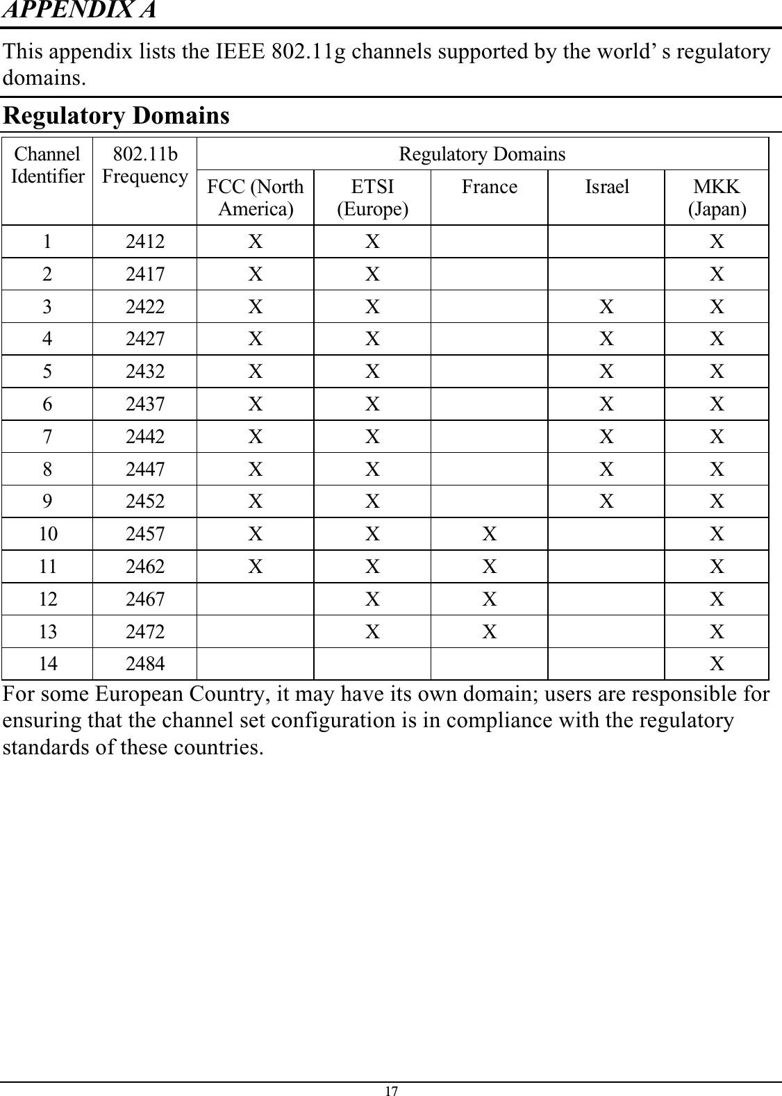
TEW421PC User Manual
USERS MANUAL
Navigation menu
Upload a User Manual
Namespaces
Wiki Guide
HTML
PDF
Info
Views
User Manual
Discussion / Help
Navigation