TRENDNET TEW430APB 802.11g WIRELESS ACCESS POINT User Manual USERS MANUAL
TRENDNET, INC. 802.11g WIRELESS ACCESS POINT USERS MANUAL
UserManual.wiki
>
TRENDNET
>
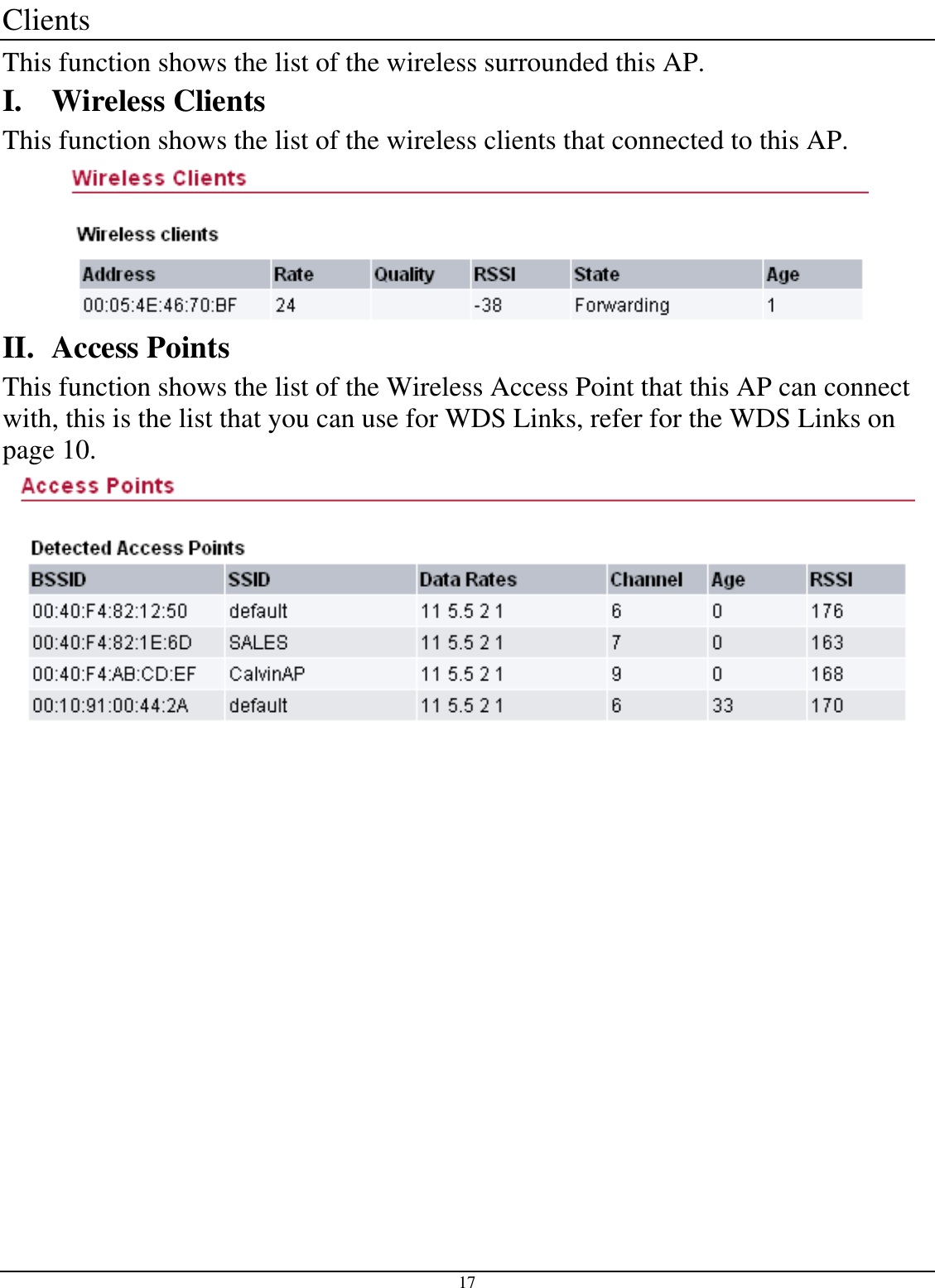
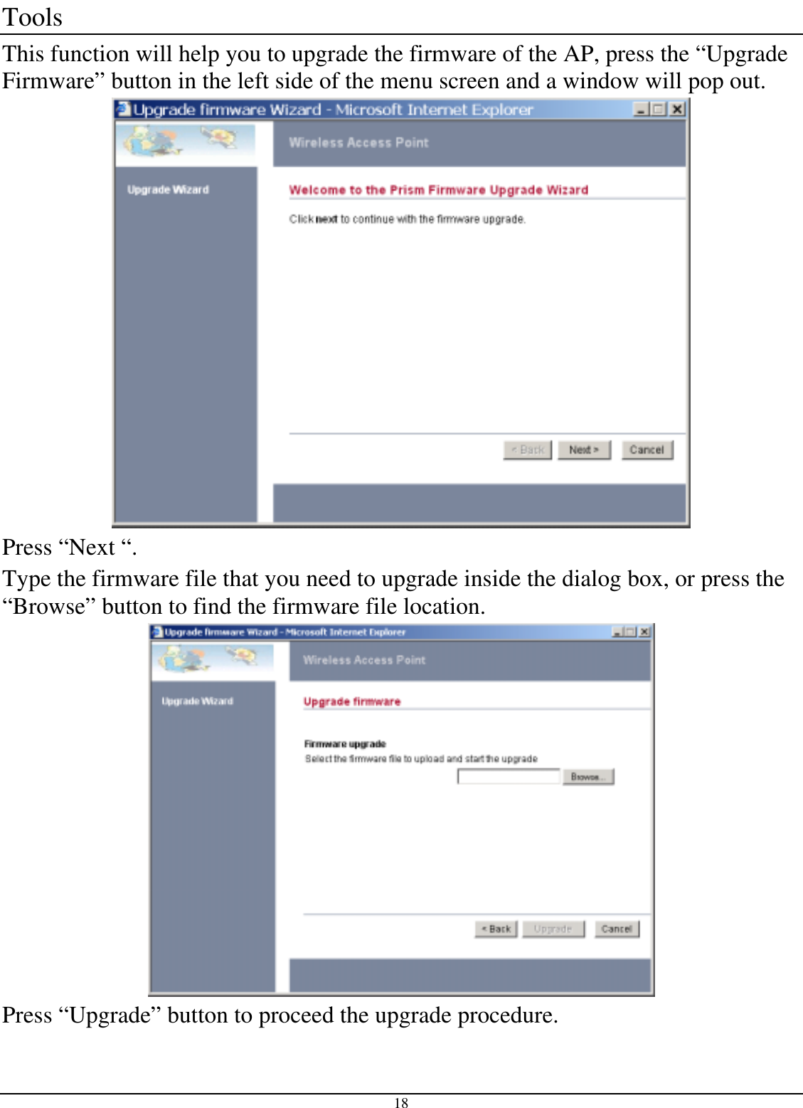
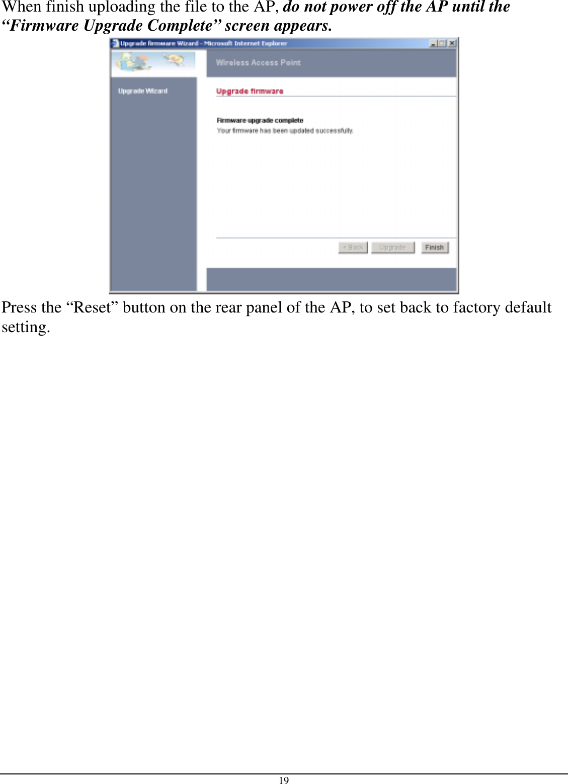
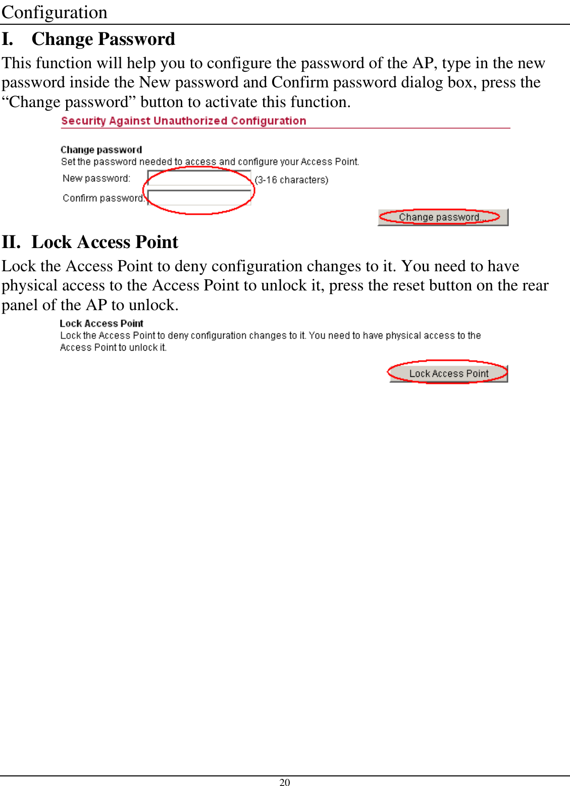
TEW430APB User Manual
USERS MANUAL
Navigation menu
Upload a User Manual
Namespaces
Wiki Guide
HTML
PDF
Info
Views
User Manual
Discussion / Help
Navigation