TRENDNET TEW610-611 108Mbps 802.11g MIMO Wireless miniPCI Module User Manual
TRENDNET, INC. 108Mbps 802.11g MIMO Wireless miniPCI Module
UserManual.wiki
>
TRENDNET
>
TEW610 611 User Manual
Users Manual
Navigation menu
Upload a User Manual
Namespaces
Wiki Guide
HTML
PDF
Info
Views
User Manual
Discussion / Help
Navigation
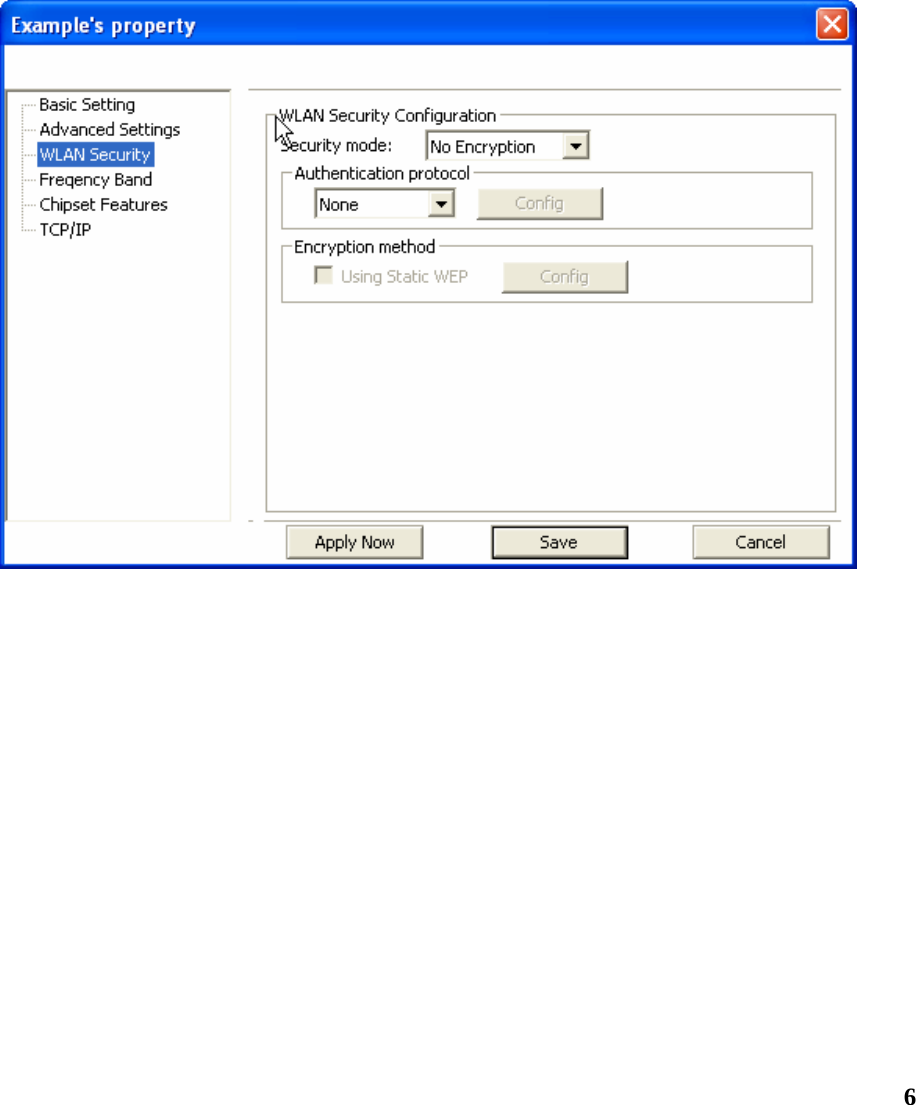
![5Getting Started This chapter introduces the module and prepares you to use the Wireless Utility. About Your 802.11g WLAN MIMO mPCI The Module is an IEEE 802.11b, and 802.11g compliant wireless LAN adapter. With the Module, you can enjoy wireless mobility within almost any wireless networking environment. The following lists the main features of your Module. 9 Your Module can communicate with other IEEE 802.11b/g compliant wireless devices. 9 Automatic rate selection. 9 Standard data transmission rates up to 54 Mbps. 9 Proprietary Atheros transmission rates of 108 Mbps 9 Offers 64-bit, 128-bit and 152-bit WEP (Wired Equivalent Privacy) data encryption for network security. 9 Supports IEEE802.1x and WPA (Wi-Fi Protected Access). 9 Low CPU utilization allowing more computer system resources for other programs. 9 Support external antennas Configuring Wireless Security This chapter covers the configuration of security options in the Wireless Utility. Configuring Security You can configure your security settings at any time. Simply select the profile you wish to edit under the [Profile] tab, select [Properties] and then choose [WLAN Security]. You are also presented with the option to configure security during the profile creation process. Whether changing the security settings of an existing profile or creating a new profile, the steps to configure your security settings remain the same. Configuring WEP](https://usermanual.wiki/TRENDNET/TEW610-611/User-Guide-572588-Page-6.png)
![71. Select [WEP] under [Security Mode] 2. Put a check mark next to [Using Static WEP] 3. Click [Config]. You will then see the screen below. 4. [WEP Method] Select the correct encryption level to match your access point. Either 64, 128, or 152-bit. The encryption level set her must match the encryption level used by your access point. a. [Authentication] You can choose between Auto, Open System, and Shared. Please see section 2.5 for more information on the different types of authentication. For most installations choosing “Auto” is the best choice. b. Enter the WEP key exactly as you did in your access point. There are three ways of generating a WEP Key: Make key using PassPhrase: a WEP Key is automatically generated as you type in any PassPhrase of your choice. Use this feature when you have used a PassPhrase to generate your WEP key on your access point. Manual Input (ASCII): You generate your own WEP Key using ASCII characters (5 characters for 64-bit, 13 characters for 128-bit, 16 characters for 152-bit)](https://usermanual.wiki/TRENDNET/TEW610-611/User-Guide-572588-Page-8.png)
![8Manual Input (Hexadecimal): You generate your own WEP Key using hexadecimal characters (10 characters for 64-bit, 26 characters for 128-bit, 32 characters for 152-bit). 5. Click [OK] to save your settings and return to the previous screen. 6. If you want to use 802.1x authentication with WEP, you will need to configure your 802.1x settings. Please see section 4.5 for details on configuring 802.1x. Configuring WPA-PSK 1. Select [WPA-PSK] under [Security Mode]. 2. Select [Encryption method]. You can choose between TKIP or AES. Most access points use TKIP for WPA-PSK. 3. Under [PSK Pass Phrase] enter the same pass phrase used to configure WPA-PSK on your access point.](https://usermanual.wiki/TRENDNET/TEW610-611/User-Guide-572588-Page-9.png)
![9Configuring WPA 1. Select [WPA-PSK] under [Security Mode]. 2. Select [Encryption method]. You can choose between TKIP or AES. Most access points use TKIP for WPA. 3. See section 4.5 for configuring 802.1x for WPA. Configuring 802.1x 1. Choose the EAP method under [Authentication protocol]. 2. Depending on the EAP method chosen the options under [User Information] will change. Configuring 802.1x – EAP-MD5 1. EAP-MD5 is only a choice when use WEP. MD5 is not allowed for WPA. 2. Enter in unique User ID and Password under [User Information]](https://usermanual.wiki/TRENDNET/TEW610-611/User-Guide-572588-Page-10.png)
![10Configuring 802.1x – EAP-LEAP 1. Enter in unique User ID and Password under [User Information] Configuring 802.1x – EAP-PEAP 1. Click [Config] under [Authentication protocol] 2. Select inner PEAP protocol. You choices are [MS-CHAP v2] or [TLS]. 3. Click [OK] to finish and return to the previous screen. 4. Enter in unique User ID and Password under [User Information]. 5. If using a user6 or server certificate click [Config certificate]. The following window appears: 6 You must first have a wired connection to a network and obtain the certificate(s) from a certificate authority (CA). Consult your network administrator for more information.](https://usermanual.wiki/TRENDNET/TEW610-611/User-Guide-572588-Page-11.png)
![11 [Use user certificate]: Put a check in the box to activate user certificate. Then select certificate from the pull down menu. [Validate server certificate]: Put a check in the box to activate server certificate. Then select the certificate authority from the pull down menu. [Server name]: Name of server used for 802.1x authentication. [Server name should match exactly]: Check this box to force server name to match exactly the same in the certificate. 6. Click [OK] to finish and return to the previous screen.](https://usermanual.wiki/TRENDNET/TEW610-611/User-Guide-572588-Page-12.png)
![12Configuring 802.1x – EAP-TLS 1. Enter in unique User ID and Password under [User Information]. 2. TLS requires you to configure both a server and user7 certificate. 3. Click [Config certificate]. The following window appears: 7 You must first have a wired connection to a network and obtain the certificate(s) from a certificate authority (CA). Consult your network administrator for more information.](https://usermanual.wiki/TRENDNET/TEW610-611/User-Guide-572588-Page-13.png)
![13 [Use user certificate]: Put a check in the box to activate user certificate. Then select certificate from the pull down menu. [Validate server certificate]: Put a check in the box to activate server certificate. Then select the certificate authority from the pull down menu. [Server name]: Name of server used for 802.1x authentication. [Server name should match exactly]: Check this box to force server name to match exactly the name in the certificate. 4. Make selections and then click [OK] to finish and return to the previous screen.](https://usermanual.wiki/TRENDNET/TEW610-611/User-Guide-572588-Page-14.png)
![14Configuring 802.1x – EAP-TTLS 1. Enter in unique User ID and Password under [User Information]. 2. Select inner TTLS protocol. You can choose between [PAP], [CHAP], [MS-CHAP], [MS-CHAPv2], or [MD5-Challenge]. 3. Click [OK] to finish and return to the previous screen. 4. Click [Config certificate]. The following window appears:](https://usermanual.wiki/TRENDNET/TEW610-611/User-Guide-572588-Page-15.png)
![15 [Use user certificate]: Put a check in the box to activate user certificate. Then select certificate from the pull down menu. [Validate server certificate]: Put a check in the box to activate server certificate. Then select the certificate authority from the pull down menu. [Server name]: Name of server used for 802.1x authentication. [Server name should match exactly]: Check this box to force server name to match exactly the name in the certificate. 5. Make selections and then click [OK] to finish and return to the previous screen. Server certificate must be configured for TTLS to work.](https://usermanual.wiki/TRENDNET/TEW610-611/User-Guide-572588-Page-16.png)