TRENDNET TEW651BR 150Mbps Wireless N Home Router User Manual UG TEW 651BR 1 02
TRENDNET, Inc. 150Mbps Wireless N Home Router UG TEW 651BR 1 02
TRENDNET >
Contents
- 1. UserMan-1_XU8TEW651BR
- 2. UserMan-2_XU8TEW651BR
UserMan-2_XU8TEW651BR
26
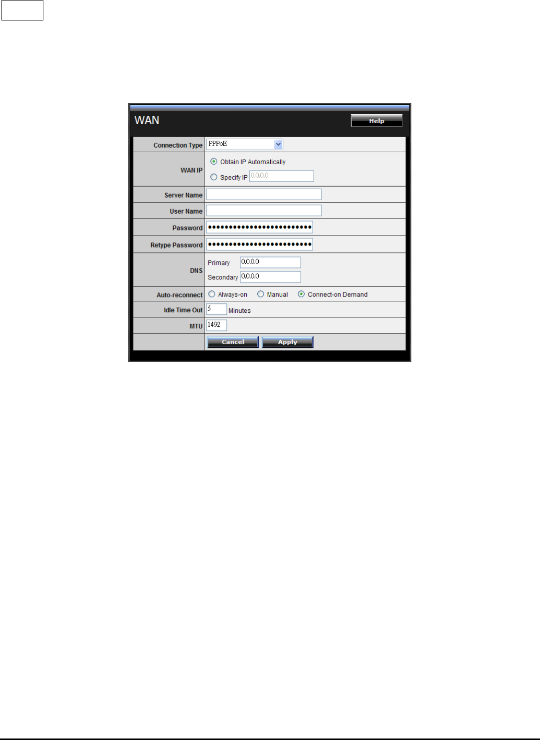
PPPoE
If connected to the Internet using a PPPoE (Dial-up xDSL) Modem, the ISP will
provide a Password and User Name, and then the ISP uses PPPoE. Choose this
option and enter the required information.
WAN IP: Select the WAN IP address Obtain from ISP automatically or enter the
specified IP address.
Server Name: Enter the server name provided by ISP (optional).
User Name: Enter the user name provided by ISP.
Password: Enter the password provided by ISP.
Retype Password: Enter the password again.
DNS: Enter the IP address of specified DNS server here, default value 0.0.0.0 is get
the DNS settings from ISP.
Auto-reconnect: Select the connection type for Always-on, Manual or Connect-on
Demand connecting.
Idle Time Out: Enter the idle time out for Connect on Daemon, when no Internet
access during the idle time, the PPPoE connection will auto disconnect.
27
MTU: Enter the specified MTU (Maximum Transmission Unit). The default value is
1492 bytes.
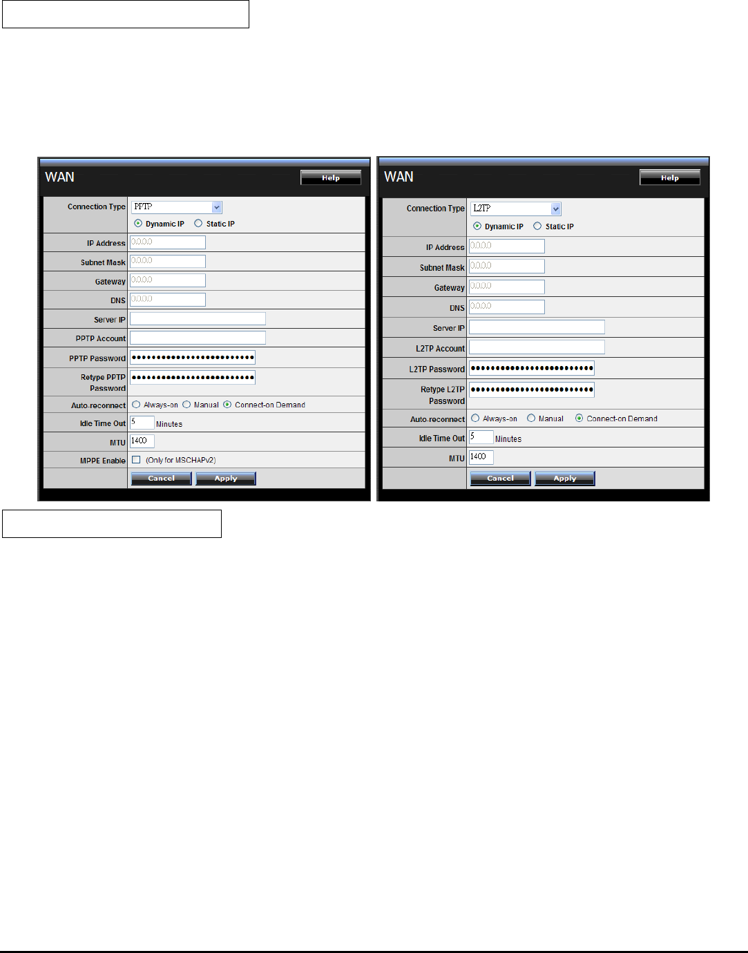
PPTP/L2TP with Dynamic IP
If connected to the Internet using a PPTP/L2TP (Dial-up xDSL) with dynamic IP
connection, enter the your Server IP, PPTP/L2TP Account and PPTP/L2TP Password,
if your ISP has provided you with a DNS IP address, enter it in the DNS field,
otherwise, leave it zero.
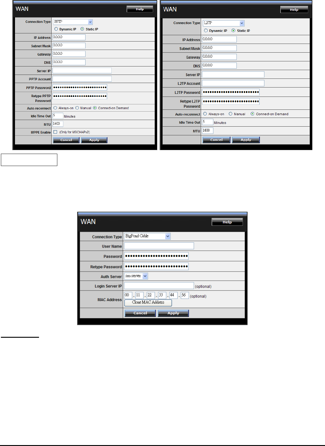
PPTP/L2TP with Static IP
If connected to the Internet using a PPTP/L2TP (Dial-up xDSL) with static IP
connection, enter the your IP Address, Subnet Mask, Gateway IP address, DNS IP
address, Server IP address, PPTP Account and PPTP Password.
28
BigPond Cable
If your ISP is Big Pond Cable, the ISP will provide a User Name, Password,
Authentication Server and Login Server IP (Optional). Choose this option and
enter the required information.
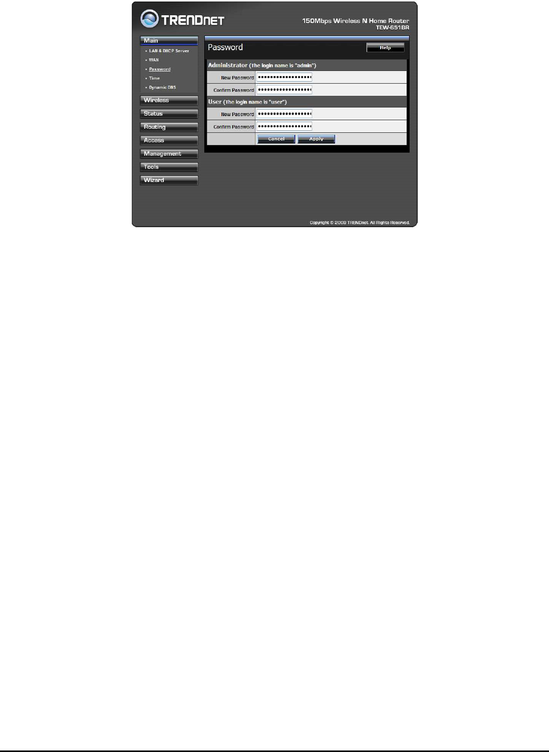
Password
This screen enables users to set administrative and user passwords. These
passwords are used to gain access to the WLAN Router interface.
29
Administrator: Type the password the Administrator will use to log into the
system. The password must be typed again for confirmation. The Administrator
can also authorize users the ability to configure the WLAN Router.
User: Type the password the User will use to log in to the system. The password
must be typed again for confirmation.
30
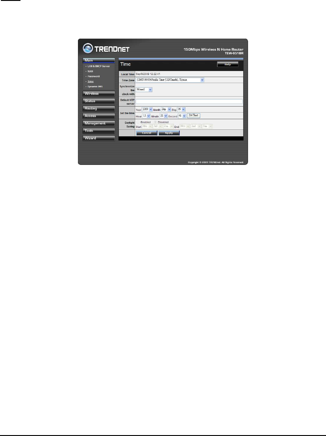
Time
This screen enables users to set the time and date for the WLAN Router's real-time
clock, select properly time zone, and enable or disable daylight saving.
Local Time: Displays the local time and date.
Time Zone: Select the time zone from the drop-down list.
Synchronize the clock with: Select the clock adjustment method form the drop-
down list.
Automatic: Automatically adjust the system time from NTP Server.
Manual: Manually adjust the system time when you press the Set Time button.
Default NTP server: The Simple Network Time Protocol (SNTP) server allows the
WLAN Router to synchronize the system clock to the global Internet through the
SNTP Server. Specify the NTP domain name or IP address in the text box.
Set the time: Manually setting the WLAN Router system time, press the Set Time
button to update the system time.
Daylight Saving: Enables users to enable or disable daylight saving time. When
enabled, select the start and end date for daylight saving time.
31
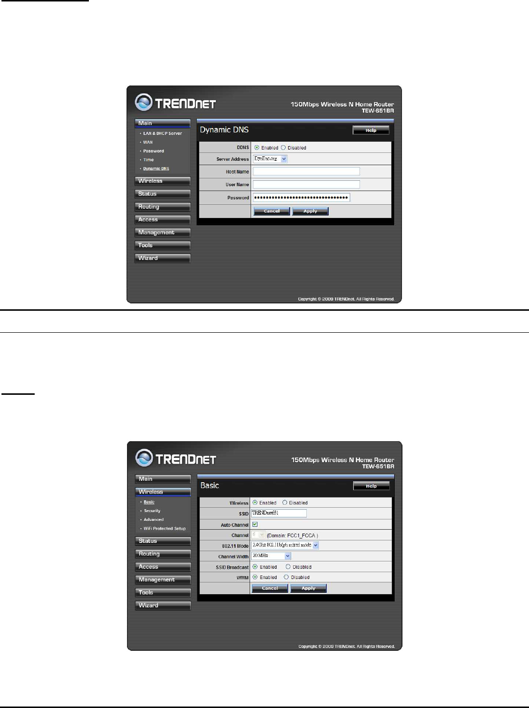
Dynamic DNS
This synchronizes the DDNS server with your current Public IP address when you
are online. First, you need to register your preferred DNS with the DDNS provider.
Then, please select the DDNS address in the Server Address and fill the related
information in the below fields: Host Name, User Name and Password.
Wireless
This section enables users to configuration the wireless communications
parameters for the WLAN Router.
Basic
This page allow user to enable and disable the wireless LAN function, create a SSID,
and select the channel for wireless communications.

32
Enable/Disable: Enables or disables wireless LAN via the WLAN Router.
SSID: Type an SSID in the text box. The SSID of any wireless device must match the
SSID typed here in order for the wireless device to access the LAN and WAN via
the WLAN Router.
Channel: Select a transmission channel for wireless communications. The channel
of any wireless device must match the channel selected here in order for the
wireless device to access the LAN and WAN via the WLAN Router.
802.11 Mode: Select one of the following:
2.4Ghz 802.11b/g mixed mode - Select if you are using both 802.11b and
802.11g wireless clients.
2.4Ghz 802.11b/g/n mixed mode - Select if you are using a mix of 802.11n,
11g, and 11b wireless clients.
2.4Ghz 802.11n only - Select if you are using 802.11n wireless clients only.
Channel Width: Select the Channel Width:
20MHz – This is the default setting. Select this option if you are not using any
802.11n wireless clients.
Auto 20/40 MHz - Select this option if you are using both 802.11n and non-
802.11n wireless devices.
SSID Broadcast: While SSID Broadcast is enabled, all wireless clients will be able to
view the WLAN Router’s SSID.
WMM: Enable the Wi-Fi Multi-Media will offer Wi-Fi networks stable that improve
the user experience for audio, video, and voice applications by prioritizing data
traffic.
33
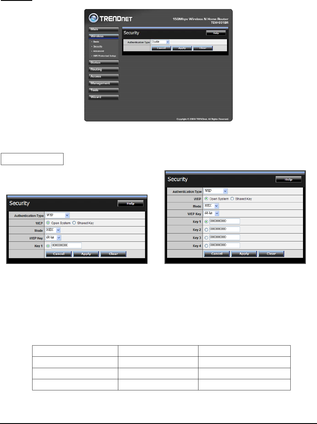
Security
Authentication Type: The authentication type default is set to open system.
There are four options: Disabled, WEP, WPA, WPA2 and WPA-Auto.
WEP Encryption
WPS Enabled WPS Disabled
WEP: Open System and Shared Key requires the user to set a WEP key to
exchange data with other wireless clients that have the same WEP key.
Mode: Select the key type: ASCII or HEX
WEP Key: Select the level of encryption from the drop-down list. The WLAN
Router supports, 64 and 128-bit encryption.
Key Length Hex ASCII
Type characters 0-9, A-F, a-f alphanumeric format
64-bit 10 characters 5 characters
128-bit 26 characters 13 characters
34
Key 1: Enables users to create WEP keys with WPS enabled. Manually enter a set
of values for Key 1.
Key 1 ~ Key 4: Enables users to create up to 4 different WEP keys with WPS
disabled. Manually enter a set of values for each key. Select a key to use by
clicking the radio button next to the key.
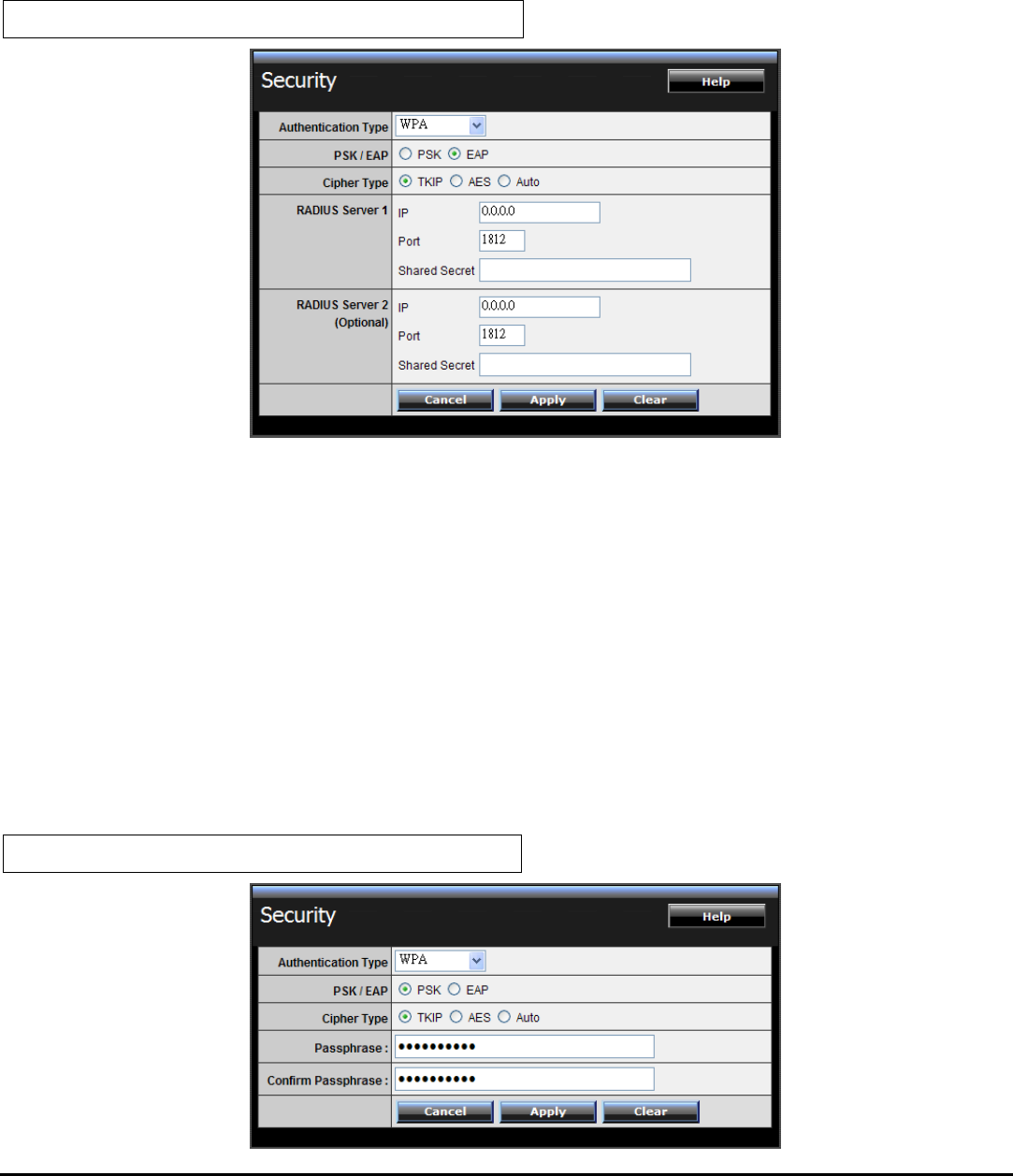
WPA/WPA2/WPA-Auto Security with EAP
If WPA, WPA2 or WPA-Auto EAP is selected, the above screen is shown. Please
set the length of the encryption key and the parameters for the RADIUS server.
Cipher Type: Select the cipher type for TKIP or AES encryption, Selected Auto for
auto detects the cipher type.
RADIUS Server 1/2:
1. Enter the IP address, Port used and Shared Secret by the Primary Radius
Server 1.
2. Enter the IP address, Port used and Shared Secret by the Secondary Radius
Server 2. (optional)
WPA/WPA2/WPA-Auto Security with PSK
35
If WPA, WPA2 or WPA-Auto PSK is selected.
Cipher Type: Select the cipher type for TKIP or AES encryption, Selected Auto for
auto detects the cipher type.
Passphrase: The length should be 8 characters at least.
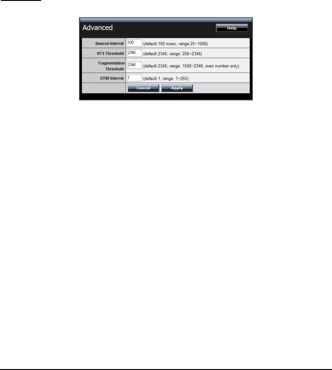
Advanced
This screen enables users to configure advanced wireless functions.
Beacon Interval: Type the beacon interval in the text box. User can specify a value
from 25 to 1000. The default beacon interval is 100.
RTS Threshold: Type the RTS (Request-To-Send) threshold in the text box. This
value stabilizes data flow. If data flow is irregular, choose values between 256 and
2346 until data flow is normalized.
Fragmentation Threshold: Type the fragmentation threshold in the text box. If
packet transfer error rates are high, choose values between 1500 and 2346 until
packet transfer rates are minimized. (NOTE: set this fragmentation threshold value
may diminish system performance.)
DTIM Interval: Type a DTIM (Delivery Traffic Indication Message) interval in the
text box. User can specify
36
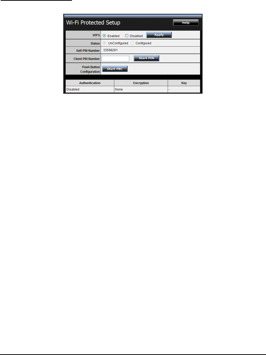
Wi-Fi Protected Setup
This screen enables users to configure the Wi-Fi Protected Setup function.
WPS: Enable or Disable the WPS (Wi-Fi Protected Setup) function
Status: Display the status (Un-configured State/Configured State) information of
WPS.
Self-PIN Number: Display the current PIN number of the WLAN Router.
Client PIN Number: Type Client’s PIN number the client uses to negotiate with the
WLAN Router via WPS connection. It is only used when users want their station to
join Router's network.
Push Button Configuration: Clicking the Start PBC button will invoke the Push
Button Configuration (PBC) method of WPS. Push the WPS button on the client
side when users want their station to join Router’s network.
37
Status
This selection enables users to view the status of the WLAN Router LAN, WAN and
Wireless connections, and view logs and statistics pertaining to connections and
packet transfers.
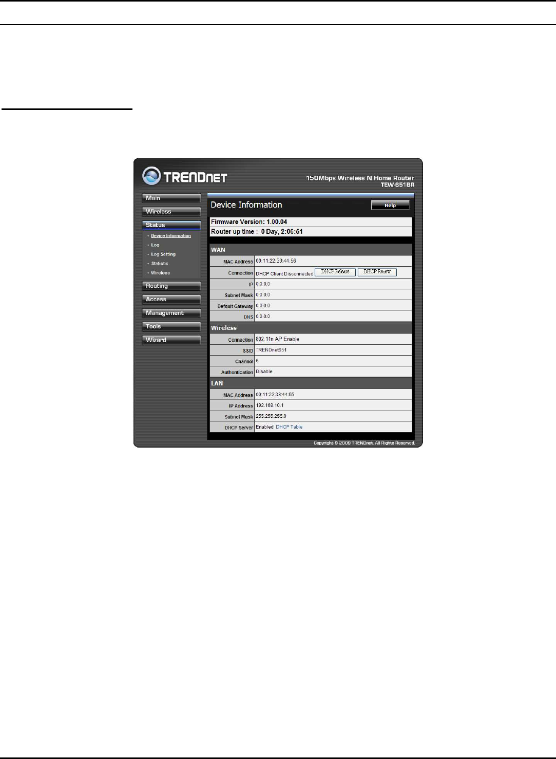
Device Information
This screen enables users to view the WLAN Router’s LAN, Wireless and WAN
configurations.
Firmware Version: Displays the latest build of the WLAN Router firmware
interface. After updating the firmware in Tools - Firmware, check this to ensure
that the firmware was successfully updated.
WAN: This section displays the WAN interface configuration including the MAC
address, Connection status, DHCP client status, IP address, Subnet mask, Default
gateway, and DNS.
Wireless: This section displays the wireless configuration information, including
the MAC address, the Connection status, SSID, Channel and Authentication type.
LAN: This section displays the LAN interface configuration including the MAC
address, IP Address, Subnet Mask, and DHCP Server Status. Click “DHCP Table” to
view a list of client stations currently connected to the WLAN Router LAN interface.
Click “DHCP Release” to release all IP addresses assigned to client stations
connected to the WAN via the WLAN Router. Click “DHCP Renew” to reassign IP
addresses to client stations connected to the WAN.
38
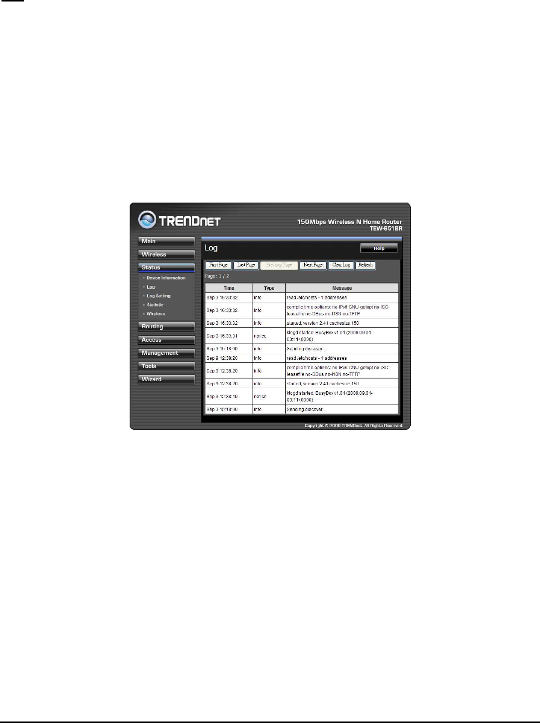
Log
This screen enables users to view a running log of Router system statistics, events,
and activities. The log displays up to 200 entries. Older entries are overwritten by
new entries. The Log screen commands are as follows:
Click “First Page” to view the first page of the log
Click “Last Page” to view the final page of the log
Click “Previous Page” to view the page just before the current page
Click “Next Page” to view the page just after the current page
Click “Clear Log” to delete the contents of the log and begin a new log
Click “Refresh” to renew log statistics
Time: Displays the time and date that the log entry was created.
Message: Displays summary information about the log entry.
39
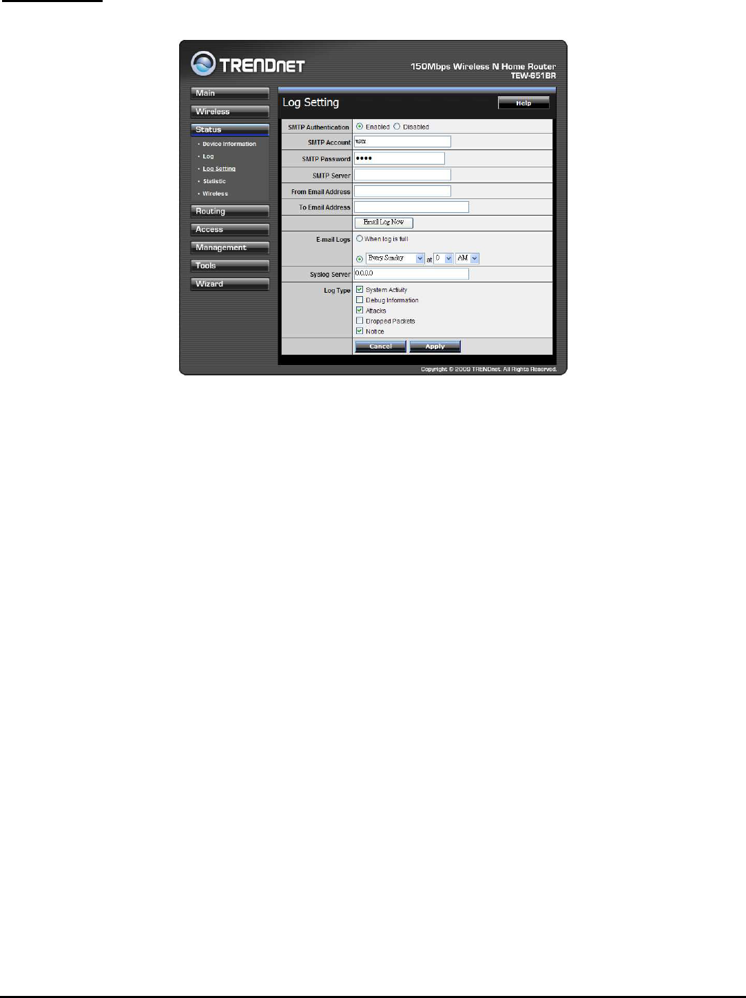
Log Setting
This screen enables users to set Router Log parameters.
SMTP Authentication: Selected the Enabled if the SMTP server need for
authentication, fill in account name and password in SMTP Account field and
SMTP Password field.
SMTP Account: If the SMTP Authentication enabled, fill in the SMTP account name
here.
SMTP Password: If the SMTP Authentication enabled, fill in the password of the
SMTP account here.
SMTP Server: Type your SMTP server address here.
From Email address: Type an email address for the log to be sent from.
To Email address: Type an email address for the log to be sent to. Click “Email Log
Now” to immediately send the current log.
E-mail Logs: Email the logs to specified email receiver.
When log is full - The time is not fixed. The log will be sent when the log is full,
which will depend on the volume of traffic.
Every day, Every Monday ... - The log is sent on the interval specified.
If "Every day" is selected, the log is sent at the time specified.
If the day is specified, the log is sent once per week, on the specified
day.
40
Select the time of day you wish the E-mail to be sent.
If the log is full before the time specified to send it, it will be sent
regardless.
Syslog Server: Type the IP address of the Syslog Server if user wants the WLAN
Router to listen and receive incoming Syslog messages.
Log Type: Enables users to select what items will be included in the log:
System Activity: Displays information related to WLAN Router operation.
Debug Information: Displays information related to errors and system
malfunctions.
Attacks: Displays information about any malicious activity on the network.
Dropped Packets: Displays information about packets that have not been
transferred successfully.
Notice: Displays important notices by the system administrator.
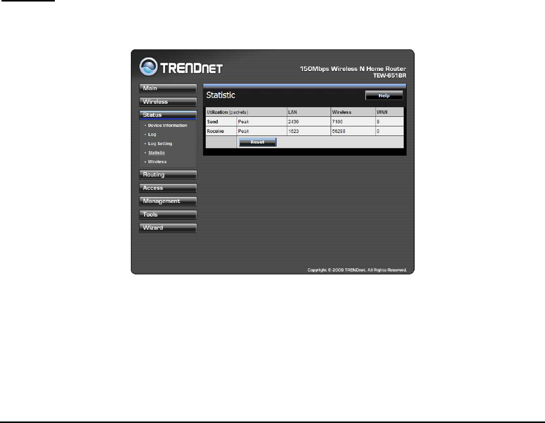
Statistic
This screen displays a table that shows the rate of packet transmission via the
WLAN Router’s LAN, Wireless and WAN ports (in bytes per second).
Click “Reset” to erase all statistics and begin logging statistics again.
41
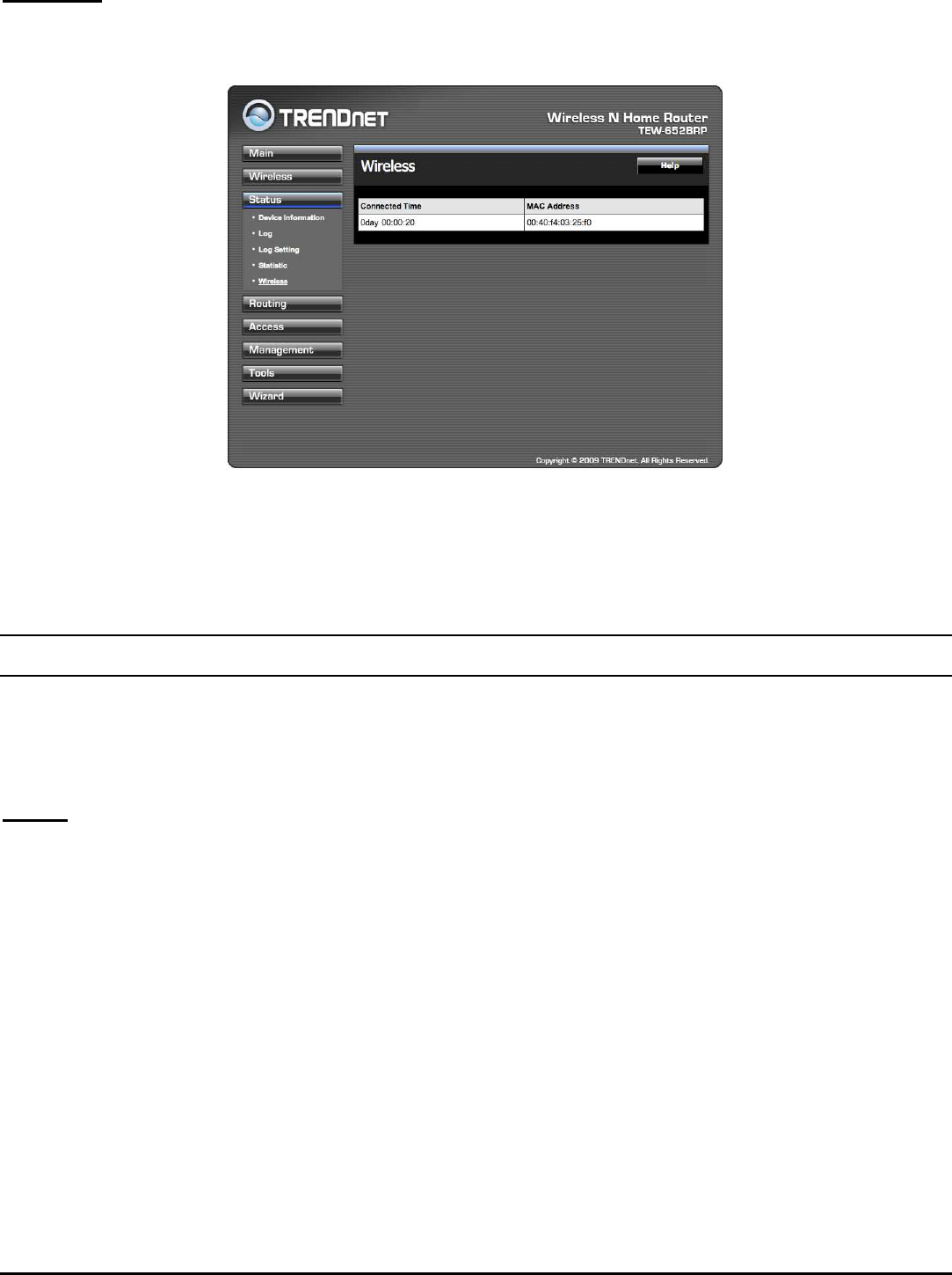
Wireless
This screen enables users to view information about wireless devices that are
connected to the WLAN Router.
Connected Time: Displays the time duration of wireless clients connection to the
WLAN Router.
MAC Address: Displays the wireless client’s MAC address.
Routing
This selection enables users to set how the WLAN Router forwards data: Static and
Dynamic. Routing Table enables users to view the information created by the
WLAN Router that displays the network interconnection topology.
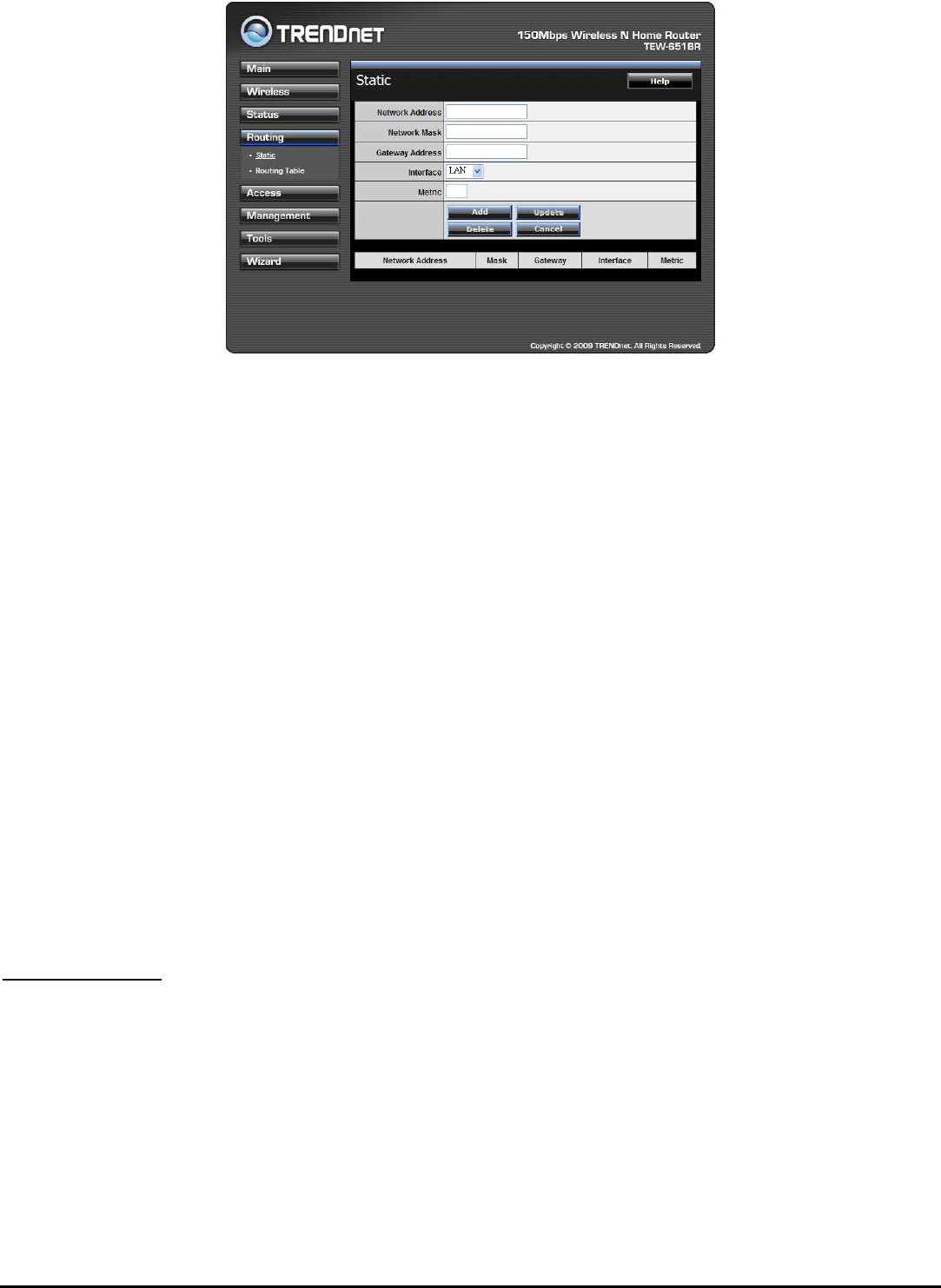
Static
It enables users to set parameters by which the WLAN Router forwards data to its
destination if the network has a static IP address.
42
Network Address: Type the static IP address the network uses to access the
Internet. Contact the ISP or network administrator for this information.
Network Mask: Type the network (subnet) mask of the network. If this field is left
blank, the network mask defaults to 255.255.255.0. Contact the ISP or network
administrator for this information.
Gateway Address: Type the gateway address of the network. Contact the ISP or
network administrator for this information.
Interface: Select an interface, WAN or LAN, to connect to the Internet.
Metric: Select which metric that the user wants to apply to this configuration.
Add: Click to add the configuration to the static IP address table at the bottom of
the page.
Update: Select one of the entries in the static IP address table at the bottom of
the page, and after changing parameters, click “Update” to confirm the changes.
Delete: Select one of the entries in the static IP address table at the bottom of the
page and click “Delete” to remove the entry.
Cancel: Click the Cancel button to erase all fields and enter new information.
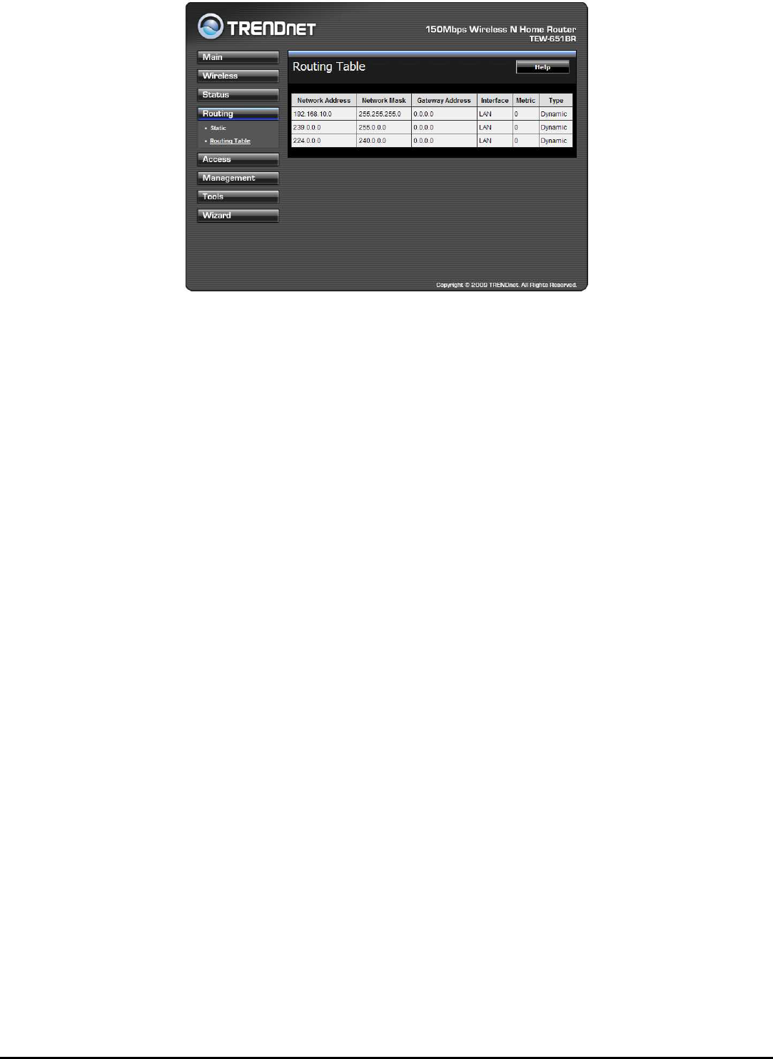
Routing Table
This screen enables users to view the routing table of the WLAN Router. The
routing table is a database created by the WLAN Router that displays the network
interconnection topology.
43
Network Address: Displays the network IP address of the connected node.
Network Mask: Displays the network (subnet) mask of the connected node.
Gateway Address: Displays the gateway address of the connected node.
Interface: Displays whether the node is connected via a WAN or LAN.
Metric: Displays the metric of the connected node.
Type: Displays whether the node has a static or dynamic IP address
44
Access
This page enables you to define access restrictions, set up protocol and IP filters,
create virtual servers, define access for special applications such as games, and set
firewall rules.
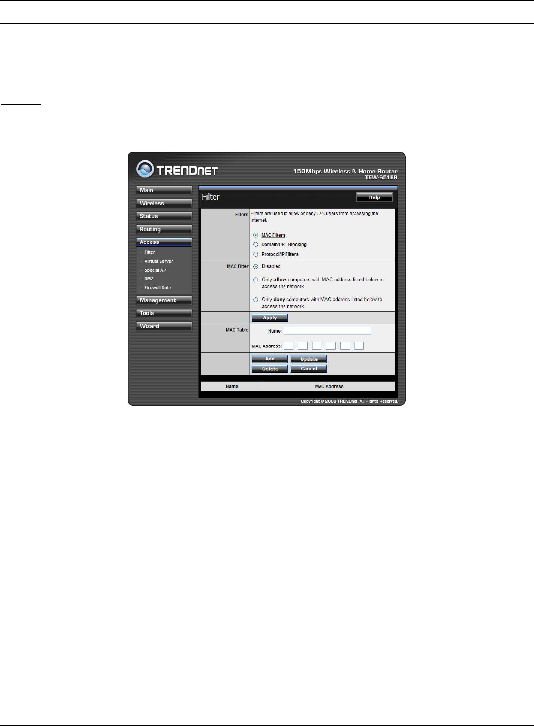
Filters
Using filters to deny or allow the users to access to the internet. Three types of
filters can be select: MAC, Domain/URL blocking, and Protocol/IP filter.
45
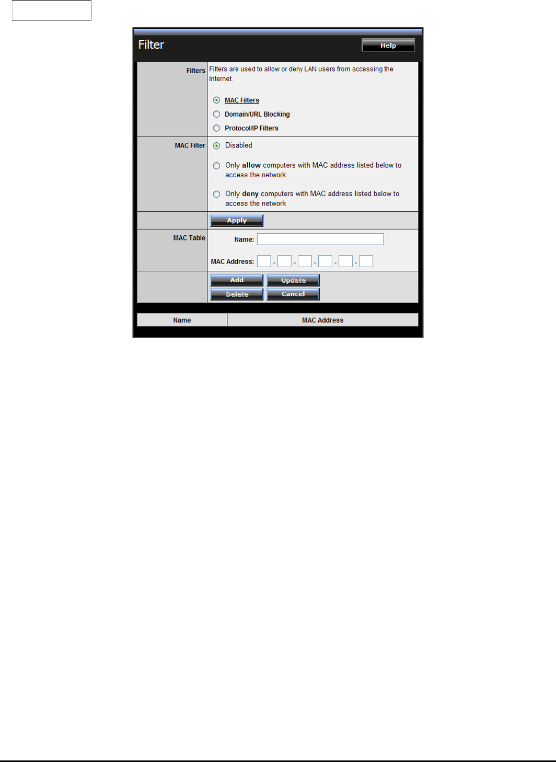
MAC Filters
MAC Filter: Enables you to allow or deny accessing the internet.
Disable: Disable the MAC filter function.
Allow: Only allow computers with MAC address listed in the MAC Table.
Deny: Computers in the MAC Table are denied Internet access.
MAC Table: Use this section to create a user profile which internet access is
denied or allowed. The user profiles are listed in the table at the bottom of the
page. (Note: Click anywhere in the item. Once the line is selected, the fields
automatically load the item's parameters, which you can edit.)
Name: Type the name of the user to be permitted/denied access.
MAC Address: Type the MAC address of the user's network interface.
Add: Click to add the user to the list at the bottom of the page.
Update: Click to update information for the user, if you have changed any of
the fields.
Delete: Select a user from the table at the bottom of the list and click Delete to
remove the user profile.
Cancel: Click Cancel to erase all fields and enter new information.
46
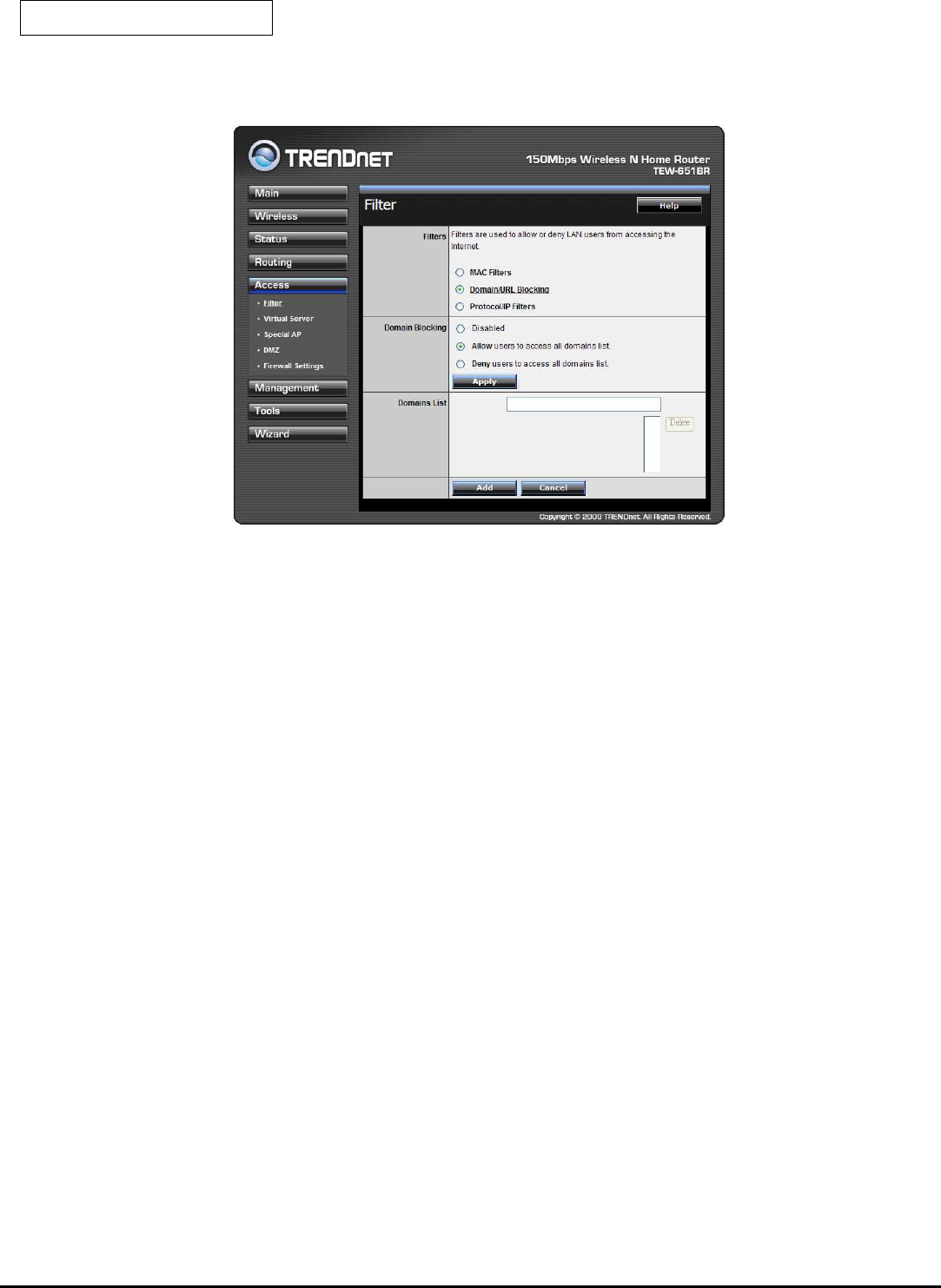
Domain/URL Blocking
You could specify the domains that allow users to access or deny by clicking one
of the two items. Also, add the specified domains in the text box.
Disable: Disable the Domain/URL Blocking function.
Allow: Allow users to access all domains except “Domains List”.
Deny: Deny users to access all domains except “Domains List”.
Domains List: List Domain/URL you will Denied or Allowed.
Delete: Select a Domain/URL from the table at the bottom of the list and
click Delete to remove the Domain/URL.
Add: Click to Add button to add domain to the Domains list.
Cancel: Click the Cancel button to erase all fields and enter new information.
47
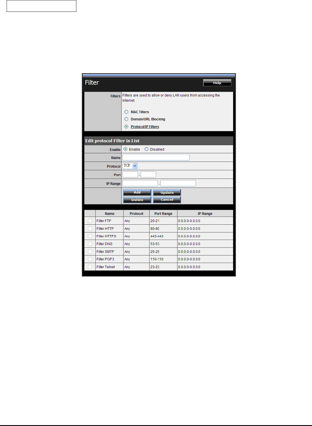
Protocol/IP Filters
This screen enables you to define a minimum and maximum IP address range
filter; all IP addresses falling within the range are not allowed accessing internet.
The IP filter profiles are listed in the table at the bottom of the page. (Note: Click
anywhere in the item. Once the line is selected, the fields automatically load the
item's parameters, which you can edit.)
Enable: Click to enable or disable the IP address filter.
Name: Type the name of the user to be denied access.
Protocol: Select a protocol (TCP or UDP) to use for the virtual server.
Port: Type the port range of the protocol.
IP Range: Type the IP range. IP addresses falling between this value and the
Range End are not allowed to access the Internet.
Add: Click to add the IP range to the table at the bottom of the screen.
Update: Click to update information for the range if you have selected a list
item and have made changes.
Delete: Select a list item and click Delete to remove the item from the list.
48
Cancel: Click the Cancel button to erase all fields and enter new information.
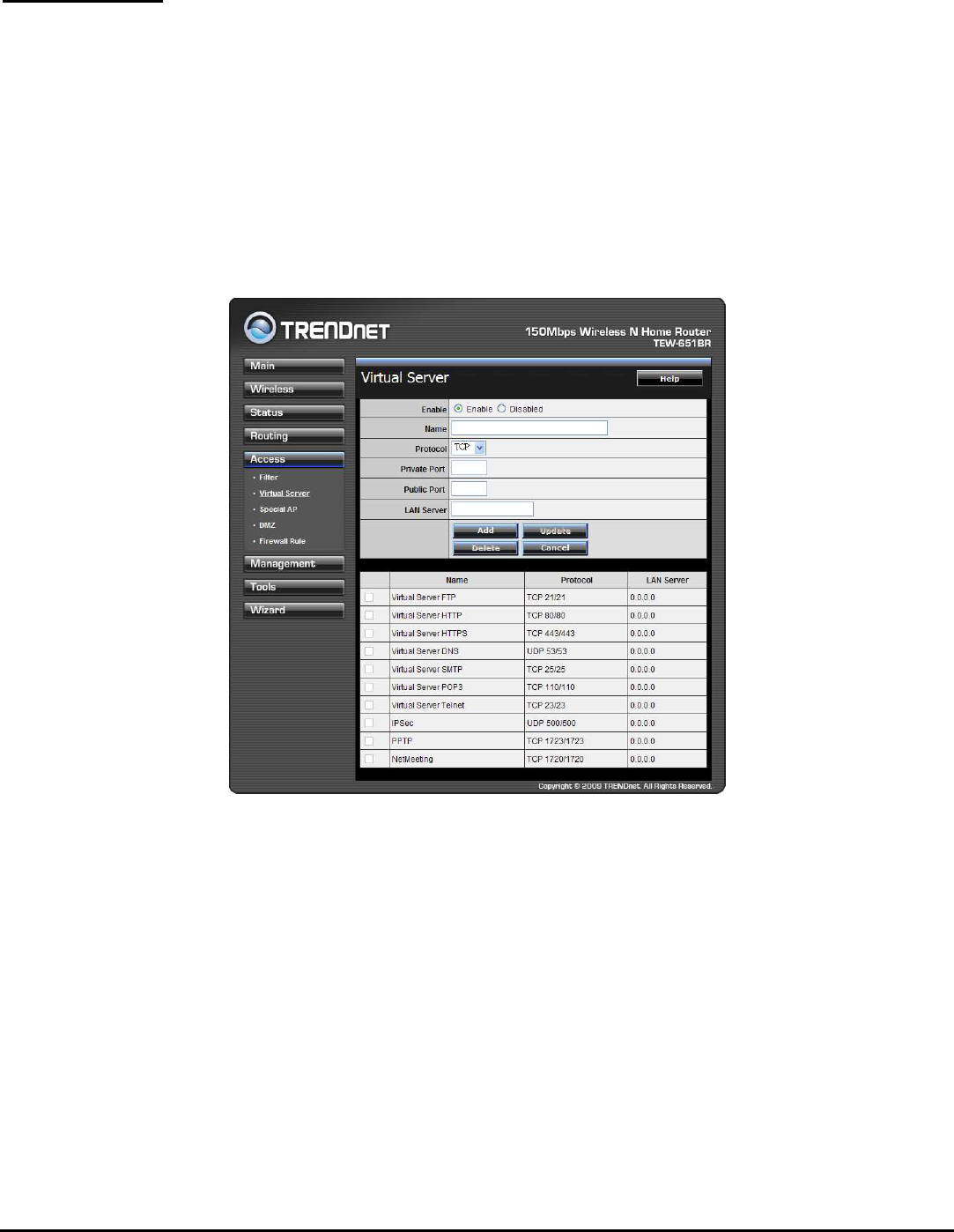
Virtual Server
This screen enables user to create a virtual server via the WLAN Router. If the
WLAN Router is set as a virtual server, remote users requesting Web or FTP
services through the WAN are directed to local servers in the LAN. The WLAN
Router redirects the request via the protocol and port numbers to the correct LAN
server. The Virtual Sever profiles are listed in the table at the bottom of the page.
Note: When selecting items in the table at the bottom, click anywhere in the item.
The line is selected, and the fields automatically load the item's parameters, which
user can edit.
Enable: Click to enable or disable the virtual server.
Name: Type a descriptive name for the virtual server.
Protocol: Select a protocol (TCP or UDP) to use for the virtual server.
Private Port: Type the port number of the computer on the LAN that is being used
to act as a virtual server.
Public Port: Type the port number on the WAN that will be used to provide access
to the virtual server.
LAN Server: Type the LAN IP address that will be assigned to the virtual server.
Add: Click to add the virtual server to the table at the bottom of the screen.
49
Update: Click to update information for the virtual server if the user has
selected a listed item and has made changes.
Delete: Select a listed item and click Delete to remove the item from the list.
Cancel: Click Cancel button to erase all fields and enter new information.
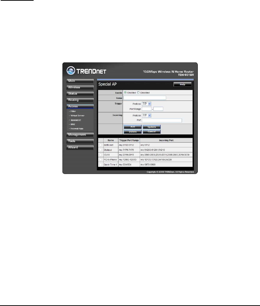
Special AP
This screen enables users to specify special applications, such as games which
require multiple connections that are blocked by NAT. The special applications
profiles are listed in the table at the bottom of the page.
Note: When selecting items in the table at the bottom, click anywhere in the item.
The line is selected, and the fields automatically load the item's parameters, which
user can edit.
Enable: Click to enable or disable the application profile. When enabled, users will
be able to connect to the application via the WLAN Router’s WAN connection.
Click “Disabled” on a profile to prevent users from accessing the application on the
WAN connection.
Name: Type a descriptive name for the application.
Trigger: Defines the outgoing communication that determines whether the user
has legitimate access to the application.
Protocol: Select the protocol (TCP, UDP, or * for TCP+UDP) that can be used
to access the application.
Port Range: Type the port range that can be used to access the application in
the text boxes.
50
Incoming: Defines which incoming communications users are permitted to
connect with.
Protocol: Select the protocol (TCP, UDP, or * for TCP+UDP) that can be used
by the incoming communication.
Port: Type the port number that can be used for the incoming
communication.
Add: Click to add the special application profile to the table at the bottom of
the screen.
Update: Click to update information for the special application if user have
selected a list item and have made changes.
Delete: Select a list item and click Delete to remove the item from the list.
Cancel: Click Cancel button to erase all fields and enter new information.
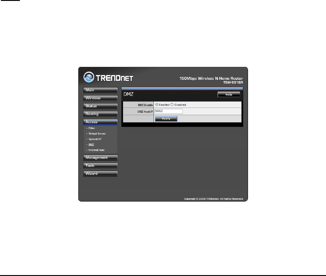
DMZ
This screen enables users to create a DMZ for those computers that cannot access
Internet applications properly through the WLAN Router and associated security
settings.
Note: Any clients added to the DMZ exposes the clients to security risks such as
viruses and unauthorized access.
Enable: Click to enable or disable the DMZ.
DMZ Host IP: Type a host IP address for the DMZ. The computer with this IP
address acts as a DMZ host with unlimited Internet access.
Apply: Click to save the settings.
51
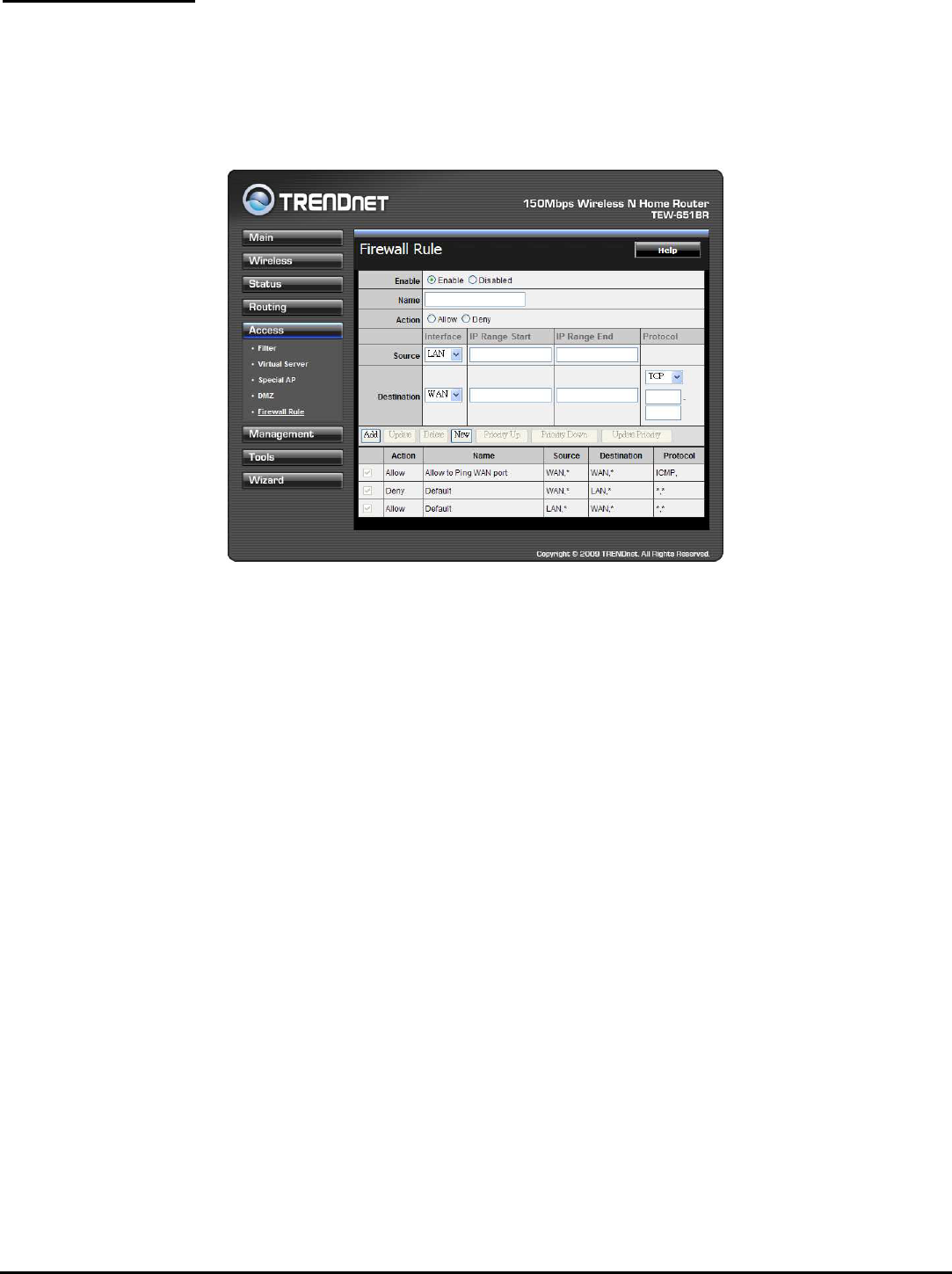
Firewall Settings
This screen enables users to set up the firewall. The WLAN Router provides basic
firewall functions, by filtering all the packets that enter the WLAN Router using a
set of rules. The rules are listed in sequential order--the lower the rule number,
the higher the priority the rule has.
Enable: Click to enable or disable the firewall rule profile.
Name: Type a descriptive name for the firewall rule profile.
Action: Select whether to allow or deny packets that conform to the rule.
Source: Defines the source of the incoming packet that the rule is applied to.
● Interface: Select which interface (WAN or LAN) the rule is applied to.
● IP Range Start: Type the start IP address that the rule is applied to.
● IP Range End: Type the end IP address that the rule is applied to.
Destination: Defines the destination of the incoming packet that the rule is
applied to.
● Interface: Select which interface (WAN or LAN) the rule is applied to.
● IP Range Start: Type the start IP address that the rule is applied to.
● IP Range End: Type the end IP address that the rule is applied to.
● Protocol: Select the protocol (TCP, UDP, or ICMP) of the destination.
● Port Range: Select the port range.
Add: Click to add the rule profile to the table at the bottom of the screen.
Update: Click to update information for the rule if the user has selected a listed
item and has made changes.
52
Delete: Select a listed item and click Delete button to remove the entry from the
list.
New: Click “New” to erase all fields and enter new information.
Priority Up: Select a rule from the list and click “Priority Up” to increase the
priority of the rule.
Priority Down: Select a rule from the list and click “Priority Down” to decrease the
priority of the rule.
Update Priority: After increasing or decreasing the priority of a rule, click “Update
Priority” to save the changes.
Management
Management enables users to set up the Remote Management feature.
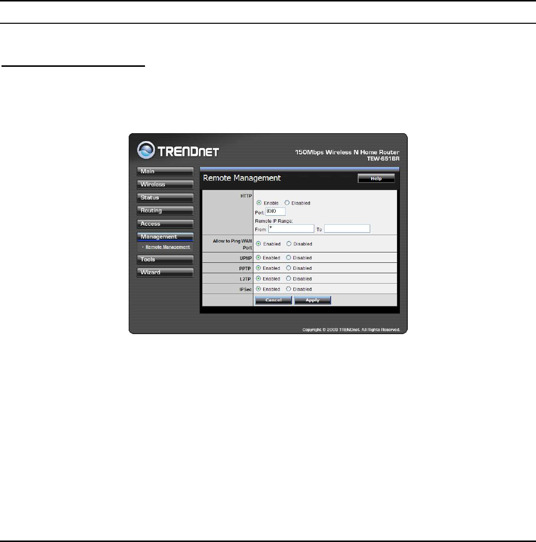
Remote Management
This screen enables users to set up remote management. Using remote
management, the WLAN Router can be configured through the WAN via a Web
browser. A user name and password are required to perform remote management.
HTTP: Enables users to set up HTTP access of the Port number, and Remote IP
Range for remote management.
Allow to Ping WAN Port: Type a range of Router IP addresses that can be pinged
from remote locations
UPnP Enable: UPnP is short for Universal Plug and Play that is a networking
architecture that provides compatibility among networking equipment, software,
and peripherals. The WLAN Router is an UPnP-enabled Router and will only work
with other UPnP devices/software. If user does not want to use the UPnP
functionality, select “Disabled” to disable it.

53
PPTP: Enables users to set up PPTP access for remote management.
L2TP: Enables users to set up L2TP access for remote management.
IPSec: Enables users to set up IPSec access for remote management.
54
Tools
This page enables users to restart the system, save and load different settings as
profiles, restore factory default settings, run a setup wizard to configure WLAN
Router settings, upgrade the firmware, and ping remote IP addresses.
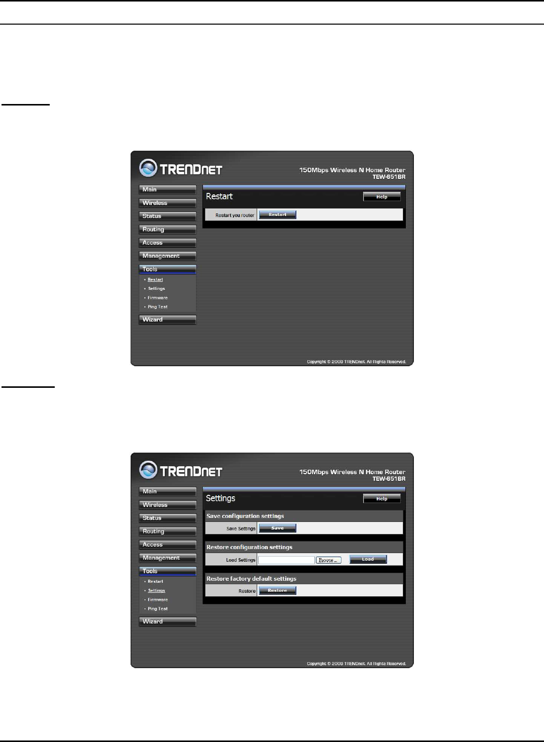
Restart
Click “Restart” to restart the system in the event the system is not performing
correctly.
Settings
This screen enables users to save settings as a profile and load profiles for
different circumstances. User can also load the factory default settings, and run a
setup wizard to configure the WLAN Router and Router interface.
Save Settings: Click “Save” to save the current configuration as a profile that can
load when necessary.
55
Load Settings: Click “Browse” and go to the location of a stored profile. Click
“Load” to load the profile's settings.
Restore Factory Default Settings: Click “Restore” to restore the default settings.
All configuration changes will lose.
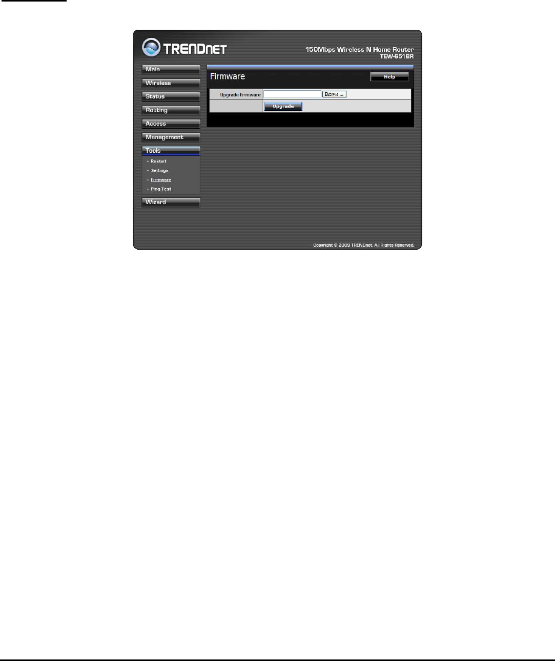
Firmware
This screen enables users to keep the WLAN Router firmware up to date.
Please follow the below instructions:
Download the latest firmware from the manufacturer's Web site, and save it to
disk.
Click “Browse” and go to the location of the downloaded firmware file.
Select the file and click “Upgrade” to update the firmware to the latest release.
56
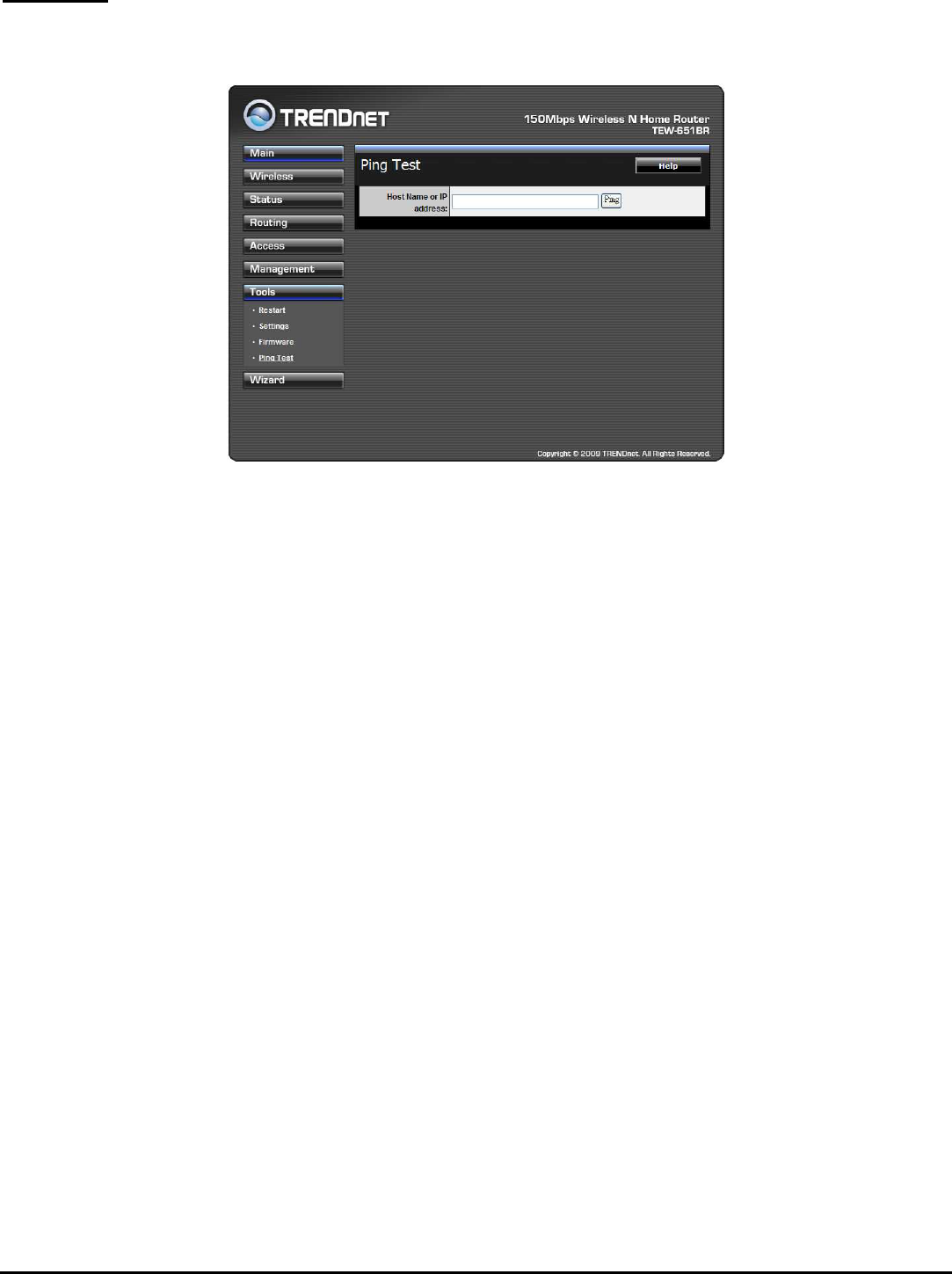
Ping Test
The ping test enables users to determine whether an IP address or host is present
on the Internet. Type the host name or IP address in the text box and click Ping.

57
TECHNICAL SPECIFICATIONS
Hardware
Standards Wired: IEEE 802.3 (10Base-T), IEEE 802.3u (100Base-TX)
Wireless: IEEE 802.11b, IEEE 802.11g, IEEE 802.11n , IEEE 802.11e QoS
WAN 1 x 10/100Mbps Auto-MDIX port (Internet)
LAN 4 x 10/100Mbps Auto-MDIX ports
WPS Button Enables Wi-Fi Protected Setup (WPS) function
Connection Type Dynamic IP, Static (Fixed) IP, PPPoE, PPTP, L2TP, Big Pond
UPnP UPnP IGD 1.0 compliant
DMZ DMZ host & Virtual Servers
DNS Static or WAN assigned DNS servers; 3 verified services for DDNS
Internet Access Control MAC Address Filter, Domain/URL Filter, Protocol/IP Filter
Logging 5 types of event logging; email report
LED Indicator Power, LAN1~LAN4, WAN, WLAN, Status
Power Adapter 5V DC, 1.2A external power adapter
Power Consumption 3.5watts (max)
Dimension (L x W x H) 150 x 110 x 30mm (5.9 x 4.3 x 1.2in)
Weight 225g (7.8oz)
Temperature Operation: 0°~ 40°C (32°F~ 104°F); Storage: -10°~ 70°C (14°F~158 °F)
Humidity Max. 90% (non-condensing)
Certifications CE, FCC
Wireless
Frequency 2.412~2.484GHz band
Antenna 1 x 2dBi fixed dipole antennas
Media Access Protocol CSMA/CA with ACK
Data Rate
802.11b: up to 11Mbps
802.11g: up to 54Mbps
802.11n: up to 150Mbps
Security WEP(HEX/ASCII): 64/128-bit
WPA(AES/TKIP): WPA/WPA2-Radius, WPA-PSK/WPA2-PSK
Output Power 25 dBm
Receiving Sensitivity
802.11b: -85dBm (typical) @ 11Mpbs
802.11g: -68dBm (typical) @ 54Mbps
802.11n: -62dBm (typical) @ 150Mbps
Channels 1~ 11 (FCC), 1~13 (ETSI)

58
LIMITED WARRANTY
TRENDnet warrants its products against defects in material and workmanship, under normal use and service, for the following
lengths of time from the date of purchase.
TEW-651BR – 3 Years Warranty
AC/DC Power Adapter, Cooling Fan, and Power Supply carry 1 year warranty.
If a product does not operate as warranted during the applicable warranty period, TRENDnet shall reserve the right, at its expense,
to repair or replace the defective product or part and deliver an equivalent product or part to the customer. The repair/replacement
unit’s warranty continues from the original date of purchase. All products that are replaced become the property of TRENDnet.
Replacement products may be new or reconditioned. TRENDnet does not issue refunds or credit. Please contact the point-of-
purchase for their return policies.
TRENDnet shall not be responsible for any software, firmware, information, or memory data of customer contained in, stored on, or
integrated with any products returned to TRENDnet pursuant to any warranty.
There are no user serviceable parts inside the product. Do not remove or attempt to service the product by any unauthorized
service center. This warranty is voided if (i) the product has been modified or repaired by any unauthorized service center, (ii) the
product was subject to accident, abuse, or improper use (iii) the product was subject to conditions more severe than those specified
in the manual.
Warranty service may be obtained by contacting TRENDnet within the applicable warranty period and providing a copy of the dated
proof of the purchase. Upon proper submission of required documentation a Return Material Authorization (RMA) number will be
issued. An RMA number is required in order to initiate warranty service support for all TRENDnet products. Products that are sent to
TRENDnet for RMA service must have the RMA number marked on the outside of return packages and sent to TRENDnet prepaid,
insured and packaged appropriately for safe shipment. Customers shipping from outside of the USA and Canada are responsible for
return shipping fees. Customers shipping from outside of the USA are responsible for custom charges, including but not limited to,
duty, tax, and other fees.
WARRANTIES EXCLUSIVE: IF THE TRENDNET PRODUCT DOES NOT OPERATE AS WARRANTED ABOVE, THE CUSTOMER’S SOLE
REMEDY SHALL BE, AT TRENDNET’S OPTION, REPAIR OR REPLACE. THE FOREGOING WARRANTIES AND REMEDIES ARE EXCLUSIVE
AND ARE IN LIEU OF ALL OTHER WARRANTIES, EXPRESSED OR IMPLIED, EITHER IN FACT OR BY OPERATION OF LAW, STATUTORY OR
OTHERWISE, INCLUDING WARRANTIES OF MERCHANTABILITY AND FITNESS FOR A PARTICULAR PURPOSE. TRENDNET NEITHER
ASSUMES NOR AUTHORIZES ANY OTHER PERSON TO ASSUME FOR IT ANY OTHER LIABILITY IN CONNECTION WITH THE SALE,
INSTALLATION MAINTENANCE OR USE OF TRENDNET’S PRODUCTS.
TRENDNET SHALL NOT BE LIABLE UNDER THIS WARRANTY IF ITS TESTING AND EXAMINATION DISCLOSE THAT THE ALLEGED DEFECT
IN THE PRODUCT DOES NOT EXIST OR WAS CAUSED BY CUSTOMER’S OR ANY THIRD PERSON’S MISUSE, NEGLECT, IMPROPER
INSTALLATION OR TESTING, UNAUTHORIZED ATTEMPTS TO REPAIR OR MODIFY, OR ANY OTHER CAUSE BEYOND THE RANGE OF THE
INTENDED USE, OR BY ACCIDENT, FIRE, LIGHTNING, OR OTHER HAZARD.
LIMITATION OF LIABILITY: TO THE FULL EXTENT ALLOWED BY LAW TRENDNET ALSO EXCLUDES FOR ITSELF AND ITS SUPPLIERS ANY
LIABILITY, WHETHER BASED IN CONTRACT OR TORT (INCLUDING NEGLIGENCE), FOR INCIDENTAL, CONSEQUENTIAL, INDIRECT,
SPECIAL, OR PUNITIVE DAMAGES OF ANY KIND, OR FOR LOSS OF REVENUE OR PROFITS, LOSS OF BUSINESS, LOSS OF INFORMATION
OR DATE, OR OTHER FINANCIAL LOSS ARISING OUT OF OR IN CONNECTION WITH THE SALE, INSTALLATION, MAINTENANCE, USE,
PERFORMANCE, FAILURE, OR INTERRUPTION OF THE POSSIBILITY OF SUCH DAMAGES, AND LIMITS ITS LIABILITY TO REPAIR,
REPLACEMENT, OR REFUND OF THE PURCHASE PRICE PAID, AT TRENDNET’S OPTION. THIS DISCLAIMER OF LIABILITY FOR DAMAGES
WILL NOT BE AFFECTED IF ANY REMEDY PROVIDED HEREIN SHALL FAIL OF ITS ESSENTIAL PURPOSE.
Governing Law: This Limited Warranty shall be governed by the laws of the state of California.

59
Some TRENDnet products include software code written by third party developers. These codes are subject to the GNU General
Public License ("GPL") or GNU Lesser General Public License ("LGPL").
Go to http://www.trendnet.com/gpl or http://www.trendnet.com Download section and look for the desired TRENDnet product to
access to the GPL Code or LGPL Code. These codes are distributed WITHOUT WARRANTY and are subject to the copyrights of the
developers. TRENDnet does not provide technical support for these codes. Please go to http://www.gnu.org/licenses/gpl.txt or
http://www.gnu.org/licenses/lgpl.txt for specific terms of each license.
PWP05202009v2
60