TRENDNET TEW672GR Dual Band Wireless N Gigabit Router User Manual WRT 790L 0530
TRENDNET, INC. Dual Band Wireless N Gigabit Router WRT 790L 0530
TRENDNET >
Users Manual
2.4/5GHz Dual-Band Wireless 802.11n(DRAFT) Giga
Router
TEW-672GR
Rev 0.7
User Manual
1
Federal Communication Commission Interference Statement
This equipment has been tested and found to comply with the limits for a Class B digital device,
pursuant to Part 15 of the FCC Rules. These limits are designed to provide reasonable protection
against harmful interference in a residential installation. This equipment generates, uses and can
radiate radio frequency energy and, if not installed and used in accordance with the instructions,
may cause harmful interference to radio communications. However, there is no guarantee that
interference will not occur in a particular installation. If this equipment does cause harmful
interference to radio or television reception, which can be determined by turning the equipment off
and on, the user is encouraged to try to correct the interference by one of the following measures:
- Reorient or relocate the receiving antenna.
- Increase the separation between the equipment and receiver.
- Connect the equipment into an outlet on a circuit different from that to which the receiver is
connected.
- Consult the dealer or an experienced radio/TV technician for help.
This device complies with Part 15 of the FCC Rules. Operation is subject to the following two
conditions: (1) This device may not cause harmful interference, and (2) this device must accept any
interference received, including interference that may cause undesired operation.
FCC Caution: Any changes or modifications not expressly approved by the party responsible for
compliance could void the user's authority to operate this equipment.
IMPORTANT NOTE:
FCC Radiation Exposure Statement:
This equipment complies with FCC radiation exposure limits set forth for an uncontrolled
environment. This equipment should be installed and operated with minimum distance 20cm
between the radiator & your body.
This transmitter must not be co-located or operating in conjunction with any other antenna or
transmitter.
For product available in the USA/Canada market, only channel 1~11 can be operated. Selection of
other channels is not possible.
This device is going to be operated in 5.15~5.25GHz frequency range, it is restricted in indoor
environment only.
The availability of some specific channels and/or operational frequency bands are country
dependent and are firmware programmed at the factory to match the intended destination. The
firmware setting is not accessible by the end user.
Copyright
This publication, including all photographs, illustrations and software, is protected under international
copyright laws, with all rights reserved. Neither this manual, nor any of the material contained herein, may
be reproduced without written consent of the author.
2
Copyright 2006
Trademark recognition
All product names used in this manual are the properties of their respective owners and are acknowledged.
3
Table of Contents
Getting Started with the WRT-790L ------------------------------------- 3
Package Contents ------------------------------------------------------- 4
Minimum System Requirements ------------------------------------ 4
Wireless LAN Networking -------------------------------------------------- 5
Introduction -------------------------------------------------------------- 9
Features ------------------------------------------------------------------- 9
Hardware Overview ---------------------------------------------------------- 10
LED Indications --------------------------------------------------------- 10
Rear Panel ---------------------------------------------------------------- 10
Installation Considerations -------------------------------------------- 11
Getting Started ----------------------------------------------------------- 11
Using the Configuration Menu ---------------------------------------------- 12
Network -------------------------------------------------------------------- 13
Wireless -------------------------------------------------------------------- 20
Advanced ------------------------------------------------------------------ 28
Administrator ------------------------------------------------------------ 42

4
Getting Started with the WRT-790L
Congratulations on purchasing the WRT-790L! This manual provides information for setting up and
configuring the WRT-790L. This manual is intended for both home users and professionals.
The following conventions are used in this manual:
THE NOTE SYMBOL INDICATES ADDITIONAL INFORMATION ON THE
TOPIC AT HAND.
THE TIP SYMBOL INDICATES HELPFULL INFORMATION AND TIPS TO
IMPROVE YOUR NETWORK EXPERIENCE.
THE CAUTION SYMBOL ALERTS YOU TO SITUATIONS THAT MAY
DEGRADE YOUR NETWORKING EXPERIENCE OR COMPROMISE
LIKE NOTES AND TIPS, THE IMPORTANT SYMBOL INDICATES
INFORMATION THAT CAN IMPROVE NETWORKING. THIS INFORMATION
SHOULD NOT BE OVERLOOKED.

5
Package Contents
WRT-790L 2.4/5GHz Dual-Band Wireless 802.11n(DRAFT) Giga Router
CAT-5 Ethernet Cable
Power Adapter (12V, 1A)
CD-ROM with Manual
Quick Installation Guide
Using a power supply with a different voltage than the one included with your product will
cause damage and void the warranty for this product.
Minimum System Requirements
Ethernet-Based Cable or DSL Modem
Computers with Windows, Macintosh, or Linux-based operating systems with an installed Ethernet
adapter and CD-ROM Drive
Internet Explorer Version 6.0 or Netscape Navigator Version 7.0 and Above

6
Wireless LAN Networking
This section provides background information on wireless LAN networking technology. Consult the
Glossary for definitions of the terminology used in this section.
THE INFORMATION IN THIS SECTION IS FOR YOUR REFERENCE. CHANGING
NETWORK SETTINGS AND PARTICULARLY SECURITY SETTTINGS SHOULD ONLY BE
DONE BY AN AUTHORIZED ADMINISTRATOR.
Transmission Rate (Transfer Rate)
The WRT-790L provides various transmission (data) rate options for you to select. In most networking
scenarios, the factory default Best (automatic) setting proves the most efficient. This setting allows your
WRT-790L to operate at the maximum transmission (data) rate. When the communication quality drops
below a certain level, the WRT-790L automatically switches to a lower transmission (data) rate.
Transmission at lower data speeds is usually more reliable. However, when the communication quality
improves again, the WRT-790L gradually increases the transmission (data) rate again until it reaches the
highest available transmission rate.
Types of Wireless Networks
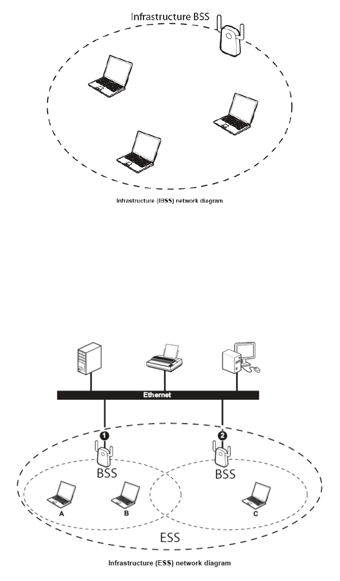
Wireless LAN networking works in either of the two modes: ad-hoc and infrastructure. In infrastructure
mode, wireless devices communicate to a wired LAN via access points. Each access point and its wireless
devices are known as a Basic Service Set (BSS). An Extended Service Set (ESS) is two or more BSSs in the
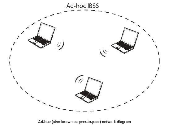
same subnet. In ad hoc mode (also known as peer-to-peer mode), wireless devices communicate with each
other directly and do not use an access point. This is an Independent BSS (IBSS).
To connect to a wired network within a coverage area using access points, set the operation mode to
Infrastructure (BSS). To set up an independent wireless workgroup without an access point, use Ad-hoc (IBSS)
mode.
AD-HOC (IBSS) NETWORK
Ad-hoc mode does not require an access point or a wired network. Two or more wireless stations
communicate directly to each other. An ad-hoc network may sometimes be referred to as an Independent
Basic Service Set (IBSS).
To set up an ad-hoc network, configure all the stations in ad-hoc mode. Use the same SSID and channel for
each station.
7
8
When a number of wireless stations are connected using a single access point, you have a Basic Service Set
(BSS).
In the ESS diagram below, communication is done through the access points, which relay data packets to
other wireless stations or devices connected to the wired network. Wireless stations can then access
resources, such as a printer, on the wired network.
9
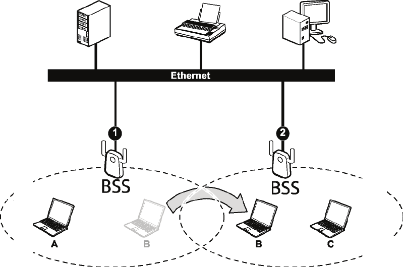
In an ESS environment, users are able to move from one access point to another without losing the
connection. In the diagram below, when the user moves from BSS (1) to BSS (2) the WLAN client devices
automatically switches to the channel used in BSS (2).
Roaming in an ESS network diagram
10
Introduction
The WRT-790L 2.4/5GHz Dual-Band Wireless 802.11n(DRAFT) Giga Router is an high-performance, wireless router
that supports high-speed wireless networking at home, at work or in public places.
Unlike most routers, the WRT-790L provides data transfers at up to 300Mbps when using 11n (Draft) connection. This
router is also back compatible with 802.11a or 802.11g or 11b devices. This means that you do not need to change your
entire network to maintain connectivity. You may sacrifice some of 11n’s (Draft) speed when you mix 11n (Draft) and
11a/b/g devices, but you will not lose the ability to communicate when you incorporate the 11n (Draft) standard into
your 11a/b/g network. You may choose to slowly change your network by gradually replacing the 11a/b/g devices with
11n (Draft) devices.
Features
Supports draft IEEE 802.11n & 11a/b/g 2.4/5GHz Dual-Band wireless Local Area Network (WLAN)
application
2.412 to 2.484GHz, 5.150 to 5250GHz, 5.725 to 5.825GHz frequency band operation
Compliant with IEEE 802.3, 802.3u, and 802.3ab standards
Support OFDM and CCK modulation
High-Speed up to 300Mbps Data Rate using IEEE 802.11n (draft) connection
Supports Cable/DSL Modems with Dynamic IP, Static IP, PPPoE, PPTP, L2TP Connection Types
Firewall features Network Address Translation (NAT)
Traffic Control with Virtual Server and DMZ
UPnP (Universal Plug & Play) and ALGs Support for Internet applications such as Email, FTP, Gaming,
Streaming, Net Meeting, Telnet, and more
Provides Additional Security of Enable/Disable SSID, Internet Access Control (IP/Port range blocking)
Supports IPSec, L2TP and PPTP VPN Pass-Through Sessions
Flash Memory for Firmware Upgrade, Save/Restore Settings
Easy Management via Web Browser (HTTP) and Remote Management
Supports 64/128-bit WEP, WPA/WPA2, and WPA-PSK/WPA2-PSK.
Easy wireless setup via PBC or PIN of WiFi Protected Setup
Work with IE6.0 and above, web browsers.
Support 4 x 10/100/1000Mbps Auto-MDIX LAN Port and 1 x 10/100/1000Mbps WAN Port (Internet)
Built-in 3 External Antennas to support high speed performance and great coverage
Support Russian ISP Cobrina WAN connection.
11
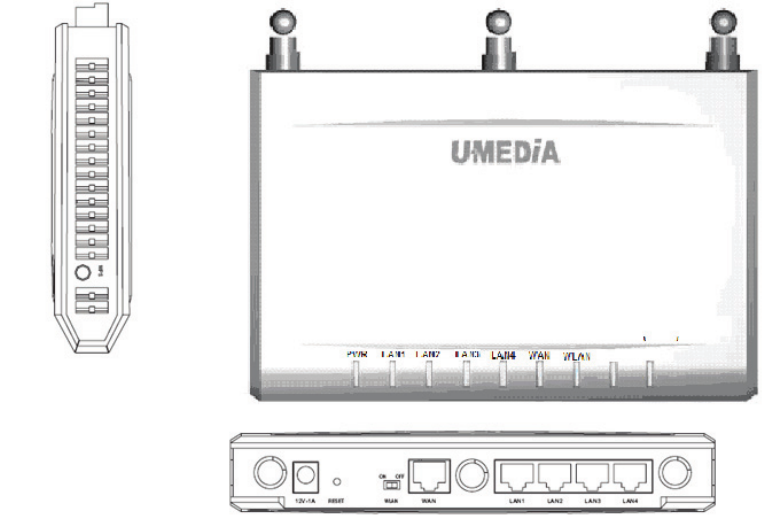
Hardware Overview
LED Indications: (from bottom to top)
PWR
WAN
LAN1
LAN2
LAN3
LAN4
Wireless
WPS
Reserve
Reserve
Rear panel: (from bottom to top)
DC-IN
RESET
WAN
LAN1
LAN2
LAN3
LAN4
12
Installation Considerations
The WRT-790L 2.4/5GHz Dual-Band Wireless 802.11n(DRAFT) Giga Router lets you access your network, using a
wireless connection, from virtually anywhere within its operating range. Keep in mind, however, that the number,
thickness and location of walls, ceilings, or other objects that the wireless signals must pass through, may limit the
range. Typical ranges vary depending on the types of materials and background RF (radio frequency) noise in your
home or business. The key to maximizing wireless range is to follow these basic guidelines:
1 Keep the number of walls and ceilings between the WRT-790L and other network devices to a minimum -
each wall or ceiling can reduce your wireless product’s range from 3-90 feet (1-30 meters.) Position your
devices so that the number of walls or ceilings is minimized.
2 Be aware of the direct line between network devices. A wall that is 1.5 feet thick (.5 meters), at a 45-degree
angle appears to be almost 3 feet (1 meter) thick. At a 2-degree angle it looks over 42 feet (14 meters) thick!
Position devices so that the signal will travel straight through a wall or ceiling (instead of at an angle) for better
reception.
3 Building Materials can impede the wireless signal - a solid metal door or aluminum studs may have a negative
effect on range. Try to position wireless devices and computers with wireless adapters so that the signal passes
through drywall or open doorways and not other materials.
4 Keep your product away (at least 3-6 feet or 1-2 meters) from electrical devices or appliances that generate
extreme RF noise.
Getting Started
For a typical wireless setup at home, please do the following:
1. You will need broadband Internet access (a Cable or DSL-subscriber line into your home or office)
2. Consult with your Cable or DSL provider for proper installation of the modem.
3. Connect the Cable or DSL modem to the WRT-790L Wireless Broadband Router (WAN port).
4. Ethernet LAN ports of the WRT-790L are Auto MDI/MDIX and will work with both
Straight-Through and Cross-Over cable.
13
Using the Configuration Menu
Whenever you want to configure your WRT-790L, you can access the Configuration Menu through your PC by
opening the Web-browser and typing in the IP Address of the WRT-790L. The WRT-790L’s default IP Address
is http://192.168.0.1
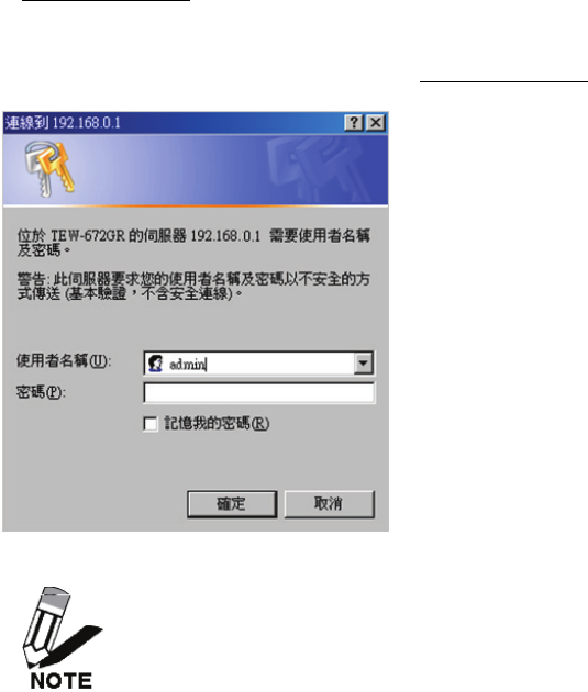
Open the Web browser.
Type in the IP Address of the Router (http://192.168.0.1).
If you have changed the default IP Address assigned to the WRT-790L, make sure to enter the
correct IP Address.
Select admin in the User Name field.
Leave the Password blank.
Click Login In.
14
Network
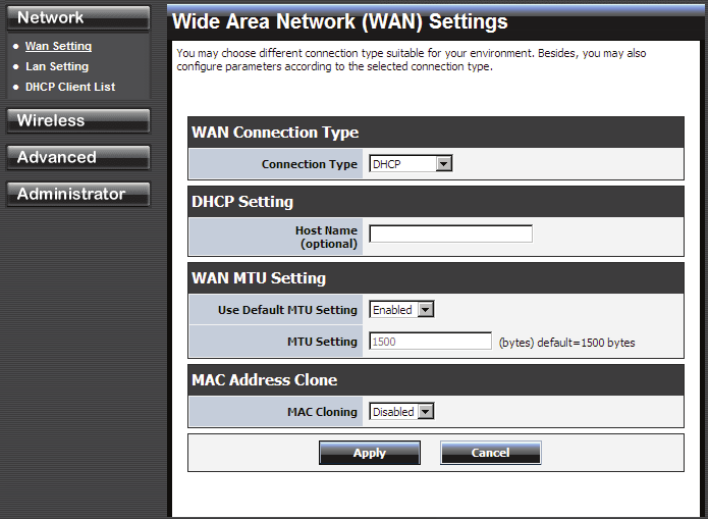
Network: Wan Setting
WAN Connection Type
There are several connection types to choose from: Static IP, DHCP, PPPoE, PPTP, L2TP, and Russia
PPTP. If you are unsure of your connection method, please contact your Internet Service Provider.
Static
Used when your ISP provides you a set IP address that does not change. The IP information is manually
entered in your IP configuration settings. You must enter the IP address, Subnet Mask, Gateway, Primary
DNS Server, and Secondary DNS Server. Your ISP provides you with all of this information.
DHCP
A method of connection where the ISP assigns your IP address when your router requests one from the
ISP's server.
Host Name: Some ISP's may check your computer's Host Name. The Host Name identifies your system
to the ISP's server.
PPPoE
Select this option if your ISP requires you to use a PPPoE (Point to Point Protocol over Ethernet)
connection. DSL providers typically use this option. This method of connection requires you to enter a
Username and Password (provided by your Internet Service Provider) to gain access to the Internet.
Reconnect Mode: Typically PPPoE connections are not always on. The router allows you to set the
reconnection mode. The settings are:
Always on: A connection to the Internet is always maintained.
On demand: A connection to the Internet is made as needed.
15
Manual: You have to open up the Web-based management interface and click the Connect button
manually any time that you wish to connect to the Internet.
Maximum Idle Time: Time interval the machine can be idle before the PPPoE connection is
disconnected. The Maximum Idle Time value is only used for the "On demand" and "Manual" reconnect
modes.
L2TP
L2TP (Layer Two Tunneling Protocol) uses a virtual private network to connect to your ISP. This
method of connection requires you to enter a Username and Password (provided by your Internet
Service Provider) to gain access to the Internet.
L2TP Server IP Address: The ISP provides this parameter, if necessary. The value may be the same as
the Gateway IP Address.
Reconnect Mode: Typically PPPoE connections are not always on. The router allows you to set the
reconnection mode. The settings are:
Always on: A connection to the Internet is always maintained.
On demand: A connection to the Internet is made as needed.
Manual: You have to open up the Web-based management interface and click the Connect button
manually any time that you wish to connect to the Internet.
Maximum Idle Time: Time interval the machine can be idle before the PPPoE connection is
disconnected. The Maximum Idle Time value is only used for the "On demand" and "Manual" reconnect
modes.
WAN Interface IP Type
Static: If your ISP has assigned a fixed IP address, select this option. The ISP provides the values for
the following fields for WAN Interface IP Setting:
IP Address, Subnet Mask , Default Gateway.
Dynamic: If the ISP's servers assign the router's IP addressing upon establishing a connection, select
this option.
PPTP
PPTP (Point to Point Tunneling Protocol) uses a virtual private network to connect to your ISP. This
method of connection is primarily used in Europe. This method of connection requires you to enter a
Username and Password (provided by your Internet Service Provider) to gain access to the Internet.
PPTP Server IP Address: The ISP provides this parameter, if necessary. The value may be the same as
the Gateway IP Address.
Reconnect Mode: Typically PPPoE connections are not always on. The router allows you to set the
reconnection mode. The settings are:
Always on: A connection to the Internet is always maintained.
On demand: A connection to the Internet is made as needed.
Manual: You have to open up the Web-based management interface and click the Connect button
manually any time that you wish to connect to the Internet.
Maximum Idle Time: Time interval the machine can be idle before the PPPoE connection is
disconnected. The Maximum Idle Time value is only used for the "On demand" and "Manual" reconnect
modes.
16
WAN Interface IP Type
Static: If your ISP has assigned a fixed IP address, select this option. The ISP provides the values for
the following fields for WAN Interface IP Setting:
IP Address, Subnet Mask , Default Gateway, and optional for DNS Server
Dynamic: If the ISP's servers assign the router's IP addressing upon establishing a connection, select
this option.
Russia PPTP
The Russia PPTP can configure IP address on the WAN interface and establish PPTP to get IP
address, subnet mask, default gateway and DNS for ANOTHER logical IP interface on WAN
port. So the physical WAN port will have 2 logical IP interfaces and can communicate with
internal ISP’s network resources and also communicate with Internet through PPTP tunnel. It is
specified by Russia Cobrina ISP, user can configure it the same as the normal PPTP and
PPTP server IP Address can use the domain name string.
WAN MTU Setting
The Maximum Transmission Unit (MTU) is a parameter that determines the largest packet size (in
bytes) that the router will send to the WAN. If LAN devices send larger packets, the router will
break them into smaller packets. Ideally, you should set this to match the MTU of the connection
to your ISP. Typical values are 1500 bytes for an Ethernet connection and 1492 bytes for a PPPoE
connection. If the router's MTU is set too high, packets will be fragmented downstream. If the
router's MTU is set too low, the router will fragment packets unnecessarily and in extreme cases
may be unable to establish some connections. In either case, network performance can suffer. t
modes.
MAC Address Clone
Each networking device has it's own unique MAC address defined by the hardware manufacturer.
Some ISP's may check your computer's MAC address. Some ISP's record the MAC address of the
network adapter in the computer or router used to initially connect to their service. The ISP will
then only grant Internet access to requests from a computer or router with this particular MAC
address. This router has a different MAC address than the computer or router that initially
connected to the ISP. If you need to change the MAC address of the rounter's WAN-side Ethernet
interface, either type in an alternate MAC address (for example, the MAC address of the router
initially connected to the ISP) or copy the MAC address of a PC. To copy the MAC address of the
computer that initially connected to the ISP, connect to the router using that computer and click
the Clone Your PC's MAC Address button. The WAN interface will then use the MAC address
of the network adapter in your computer.
17
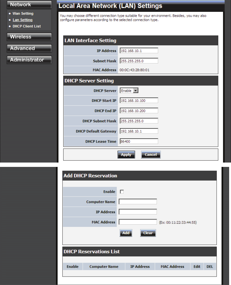
Network: Lan Setting
LAN Interface Setting
IP Address
The IP address of the this device on the local area network. Assign any unused IP address in the range of
IP addresses available for the LAN. For example, 192.168.0.101.
Subnet Mask
The subnet mask of the local area network.
DHCP Server Settings
DHCP stands for Dynamic Host Configuration Protocol. The DHCP section is where you configure the
built-in DHCP Server to assign IP addresses to the computers and other devices on your local area
18
network (LAN).
Enable DHCP Server
Once your router is properly configured and this option is enabled, the DHCP Server will manage the IP
addresses and other network configuration information for computers and other devices connected to
your Local Area Network. There is no need for you to do this yourself.
The computers (and other devices) connected to your LAN also need to have their TCP/IP configuration
set to "DHCP" or "Obtain an IP address automatically". When you set Enable DHCP Server, the
following options are displayed.
DHCP IP Address Range
These two IP values (Start and End) define a range of IP addresses that the DHCP Server uses when
assigning addresses to computers and devices on your Local Area Network. Any addresses that are
outside of this range are not managed by the DHCP Server; these could, therefore, be used for manually
configured devices or devices that cannot use DHCP to obtain network address details automatically.
It is possible for a computer or device that is manually configured to have an address that does reside
within this range. In this case the address should be reserved, so that the DHCP Server knows that this
specific address can only be used by a specific computer or device.
Your router, by default, has a static IP address of 192.168.0.1. This means that addresses 192.168.0.2 to
192.168.0.254 can be made available for allocation by the DHCP Server.
Subnet Mask
The subnet mask of the local area network.
Gateway
The IP address of the router on the local area network. For example, 192.168.0.1.
DHCP Lease Time
The amount of time that a computer may have an IP address before it is required to renew the lease. The
lease functions just as a lease on an apartment would. The initial lease designates the amount of time
before the lease expires. If the tenant wishes to retain the address when the lease is expired then a new
lease is established. If the lease expires and the address is no longer needed than another tenant may use
the address.
Add/Edit DHCP Reservation
This option lets you reserve IP addresses, and assign the same IP address to the network device with the
specified MAC address any time it requests an IP address. This is almost the same as when a device has
a static IP address except that the device must still request an IP address from the router. The router will
provide the device the same IP address every time. DHCP Reservations are helpful for server computers
on the local network that are hosting applications such as Web and FTP. Servers on your network should
either use a static IP address or use this option.
Computer Name
You can assign a name for each computer that is given a reserved IP address. This may help you keep
track of which computers are assigned this way. Example: Game Server.
IP Address:
The LAN address that you want to reserve.
MAC Address

19
To input the MAC address of your system, enter it in manually or connect to the router's
Web-Management interface from the system and click the Copy Your PC's MAC Address button.
A MAC address is usually located on a sticker on the bottom of a network device. The MAC address is
comprised of twelve digits. Each pair of hexadecimal digits are usually separated by dashes or colons
such as 00-0D-88-11-22-33 or 00:0D:88:11:22:33. If your network device is a computer and the network
card is already located inside the computer, you can connect to the router from the computer and click
the Copy Your PC's MAC Address button to enter the MAC address.
Clear
Re-initialize this area of the screen, discarding any changes you have made.
DHCP Reservations List
This shows clients that you have specified to have reserved DHCP addresses. Click the Enable checkbox
at the left to directly activate or de-activate the entry. An entry can be changed by clicking the Edit icon
or can be deleted by clicking the Delete icon. When you click the Edit icon, the item is highlighted, and
the "Edit DHCP Reservation" section is activated for editing.
20
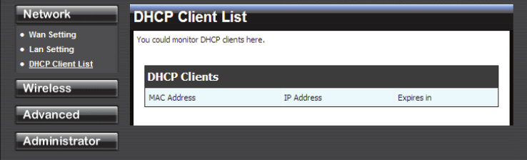
Network: DHCP Client List
DHCP Client List
In this section you can see what LAN devices are currently leasing IP addresses.
21
Wireless
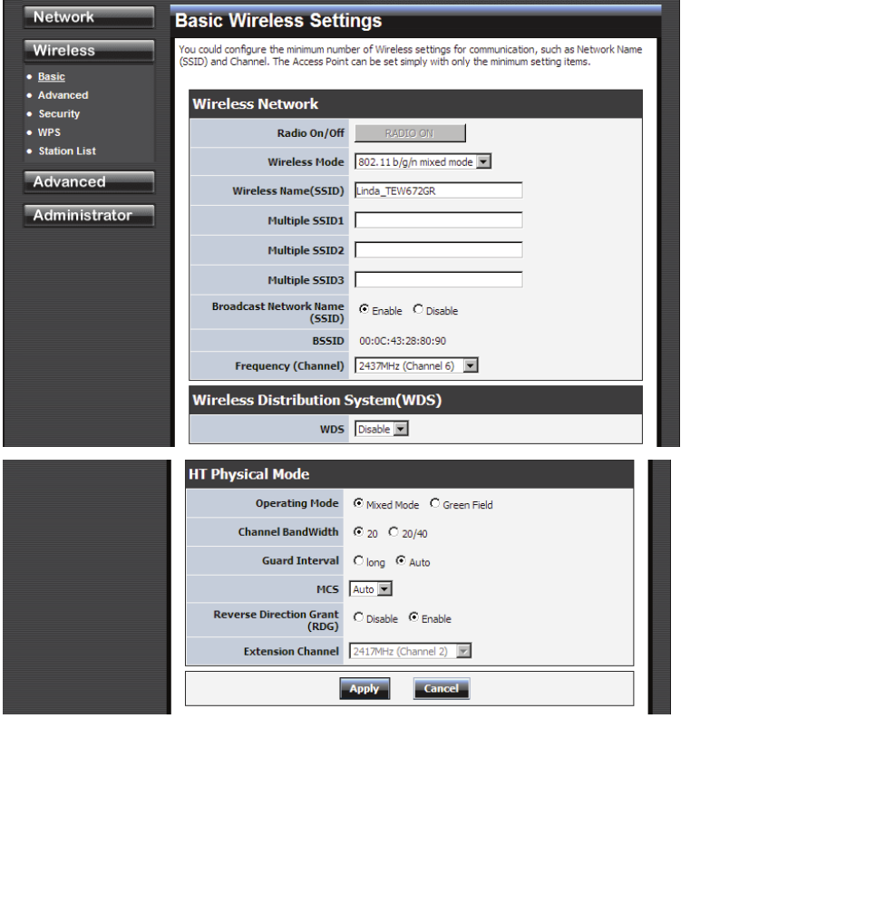
Wireless: Basic
Radio On/Off
This indicates the wireless operating status. The wireless can be turned on or off by the slide switch.
When the radio is on, the following parameters are in effect.
Wireless Mode
If all of the wireless devices you want to connect with this router can connect in the same transmission
mode, you can improve performance slightly by choosing the appropriate "Only" mode. If you have
some devices that use a different transmission mode, choose the appropriate "Mixed" mode.
Wireless Network Name (SSID)
When you are browsing for available wireless networks, this is the name that will appear in the list
(unless Visibility Status is set to Invisible, see below). This name is also referred to as the SSID. For
security purposes, it is highly recommended to change from the pre-configured network name.
Frequency (Channel)

22
A wireless network uses specific channels in the wireless spectrum to handle communication between
clients. Some channels in your area may have interference from other electronic devices. Choose the
clearest channel to help optimize the performance and coverage of your wireless network.
23
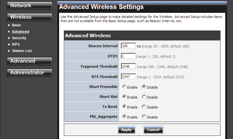
Wireless: Advanced
Beacon Interval
Beacons are packets sent by a wireless router to synchronize wireless devices. Specify a Beacon Period
value between 20 and 1000. The default value is set to 100 milliseconds.
DTIM
A DTIM is a countdown informing clients of the next window for listening to broadcast and multicast
messages. When the wireless router has buffered broadcast or multicast messages for associated clients,
it sends the next DTIM with a DTIM Interval value. Wireless clients detect the beacons and awaken to
receive the broadcast and multicast messages. The default value is 1. Valid settings are between 1 and
255.
Fragmentation Threshold
Wireless frames can be divided into smaller units (fragments) to improve performance in the presence of
RF interference and at the limits of RF coverage. Fragmentation will occur when frame size in bytes is
greater than the Fragmentation Threshold. This setting should remain at its default value of 2346 bytes.
Setting the Fragmentation value too low may result in poor performance.
RTS Threshold
When an excessive number of wireless packet collisions are occurring, wireless performance can be
improved by using the RTS/CTS (Request to Send/Clear to Send) handshake protocol. The wireless
transmitter will begin to send RTS frames (and wait for CTS) when data frame size in bytes is greater
than the RTS Threshold. This setting should remain at its default value of 2346 bytes.
Short Preamble and Slot
Using a short (400ns) guard interval can increase throughput. However, it can also increase error rate in
some installations, due to increased sensitivity to radio-frequency reflections. Select the option that
works best for your installation.
24
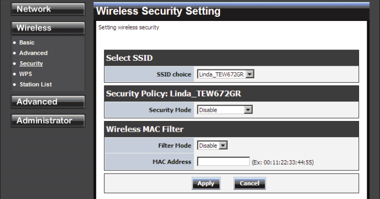
Wireless: Security
Security Mode
Unless one of these encryption modes is selected, wireless transmissions to and from your wireless
network can be easily intercepted and interpreted by unauthorized users.
WEP
A method of encrypting data for wireless communication intended to provide the same level of privacy
as a wired network. WEP is not as secure as WPA encryption. To gain access to a WEP network, you
must know the key. The key is a string of characters that you create. When using WEP, you must
determine the level of encryption. The type of encryption determines the key length. 128-bit encryption
requires a longer key than 64-bit encryption. Keys are defined by entering in a string in HEX
(hexadecimal - using characters 0-9, A-F) or ASCII (American Standard Code for Information
Interchange - alphanumeric characters) format. ASCII format is provided so you can enter a string that is
easier to remember. The ASCII string is converted to HEX for use over the network. Four keys can be
defined so that you can change keys easily. A default key is selected for use on the network.
WPA-Personal and WPA-Enterprise
Both of these options select some variant of Wi-Fi Protected Access (WPA) -- security standards
published by the Wi-Fi Alliance. The WPA Mode further refines the variant that the router should
employ.
WPA Mode: WPA is the older standard; select this option if the clients that will be used with the router
only support the older standard. WPA2 is the newer implementation of the stronger IEEE 802.11i
security standard. With the "WPA2" option, the router tries WPA2 first, but falls back to WPA if the
client only supports WPA. With the "WPA2 Only" option, the router associates only with clients that
also support WPA2 security.
Cipher Type: The encryption algorithm used to secure the data communication. TKIP (Temporal Key
Integrity Protocol) provides per-packet key generation and is based on WEP. AES (Advanced
Encryption Standard) is a very secure block based encryption. With the "TKIP and AES" option, the
router negotiates the cipher type with the client, and uses AES when available.
Group Key Update Interval: The amount of time before the group key used for broadcast and multicast
data is changed.

25
Group Key Update Interval: The amount of time before the group key used for broadcast and
multicast data is changed.
WPA-Personal
This option uses Wi-Fi Protected Access with a Pre-Shared Key (PSK).
Pre-Shared Key: The key is entered as a pass-phrase of up to 63 alphanumeric characters in ASCII
(American Standard Code for Information Interchange) format at both ends of the wireless connection. It
cannot be shorter than eight characters, although for proper security it needs to be of ample length and
should not be a commonly known phrase. This phrase is used to generate session keys that are unique
for each wireless client.
WPA-Enterprise
This option works with a RADIUS Server to authenticate wireless clients. Wireless clients should have
established the necessary credentials before attempting to authenticate to the Server through this
Gateway. Furthermore, it may be necessary to configure the RADIUS Server to allow this Gateway to
authenticate users.
Authentication Timeout: Amount of time before a client will be required to re-authenticate.
RADIUS Server IP Address: The IP address of the authentication server.
RADIUS Server Port: The port number used to connect to the authentication server.
RADIUS Server Shared Secret: A pass-phrase that must match with the authentication server.
Wireless MAC Filtering
Choose the type of MAC filtering needed.
Turn MAC Filtering Disable: When "Disable" is selected, MAC addresses are not used to control
network access.
Add MAC Filtering Rule
Use this section to add MAC addresses to the list below.
MAC Address
Enter the MAC address of a computer that you want to control with MAC filtering. Computers that have
obtained an IP address from the router's DHCP server will be in the DHCP Client List. Select a device
from the drop down menu.
26
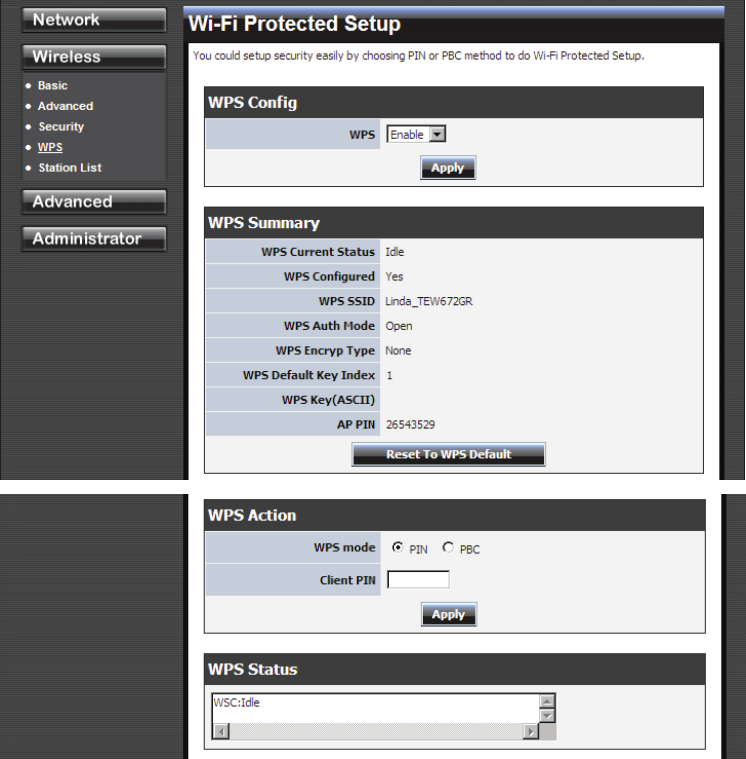
Wireless: WPS
WPS
Enable
Enable the WPS feature.
Lock Wireless Security Settings
Locking the wireless security settings prevents the settings from being changed by any new external
registrar using its PIN. Devices can still be added to the wireless network using WPS.
PIN Settings
A PIN is a unique number that can be used to add the router to an existing network or to create a new
network. The default PIN may be printed on the bottom of the router. For extra security, a new PIN can
be generated. You can restore the default PIN at any time. Only the Administrator ("admin" account) can
change or reset the PIN.
Current PIN
Shows the current value of the router's PIN.
Reset To WPS Default
27
Restore the default PIN of the router.
Generate New PIN
Create a random number that is a valid PIN. This becomes the router's PIN. You can then copy this PIN
to the user interface of the registrar.
28
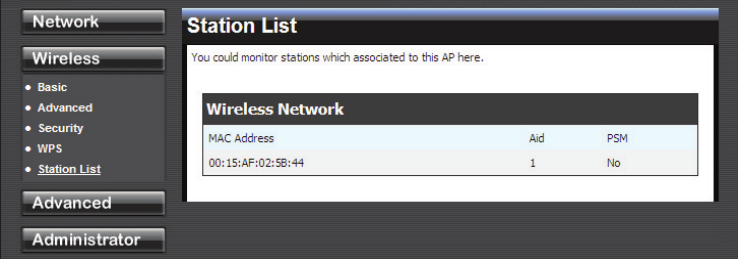
Wireless: Station List
29
Advanced
Advanced: DMZ
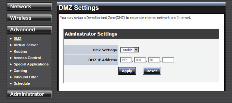
DMZ Setting
DMZ means "Demilitarized Zone." If an application has trouble working from behind the router, you
can expose one computer to the Internet and run the application on that computer.
When a LAN host is configured as a DMZ host, it becomes the destination for all incoming packets that
do not match some other incoming session or rule. If any other ingress rule is in place, that will be used
instead of sending packets to the DMZ host; so, an active session, virtual server, active port trigger, or
port forwarding rule will take priority over sending a packet to the DMZ host. (The DMZ policy
resembles a default port forwarding rule that forwards every port that is not specifically sent anywhere
else.)
The router provides only limited firewall protection for the DMZ host. The router does not forward a
TCP packet that does not match an active DMZ session, unless it is a connection establishment packet
(SYN). Except for this limited protection, the DMZ host is effectively "outside the firewall". Anyone
considering using a DMZ host should also consider running a firewall on that DMZ host system to
provide additional protection.
Packets received by the DMZ host have their IP addresses translated from the WAN-side IP address of
the router to the LAN-side IP address of the DMZ host. However, port numbers are not translated; so
applications on the DMZ host can depend on specific port numbers.
The DMZ capability is just one of several means for allowing incoming requests that might appear
unsolicited to the NAT. In general, the DMZ host should be used only if there are no other alternatives,
because it is much more exposed to cyberattacks than any other system on the LAN. Thought should be
given to using other configurations instead: a virtual server, a port forwarding rule, or a port trigger.
Virtual servers open one port for incoming sessions bound for a specific application (and also allow port
redirection and the use of ALGs). Port forwarding is rather like a selective DMZ, where incoming traffic
targeted at one or more ports is forwarded to a specific LAN host (thereby not exposing as many ports as
a DMZ host). Port triggering is a special form of port forwarding, which is activated by outgoing traffic,
and for which ports are only forwarded while the trigger is active.
Few applications truly require the use of the DMZ host. Following are examples of when a DMZ host
might be required:
• A host needs to support several applications that might use overlapping ingress ports such that
two port forwarding rules cannot be used because they would potentially be in conflict.

30
• To handle incoming connections that use a protocol other than ICMP, TCP, UDP, and IGMP
(also GRE and ESP, when these protocols are enabled by the PPTP and IPSec ALGs ).
Enable DMZ
Putting a computer in the DMZ may expose that computer to a variety of security risks. Use of this
option is only recommended as a last resort.
DMZ IP Address
Specify the LAN IP address of the LAN computer that you want to have unrestricted Internet
communication.
31
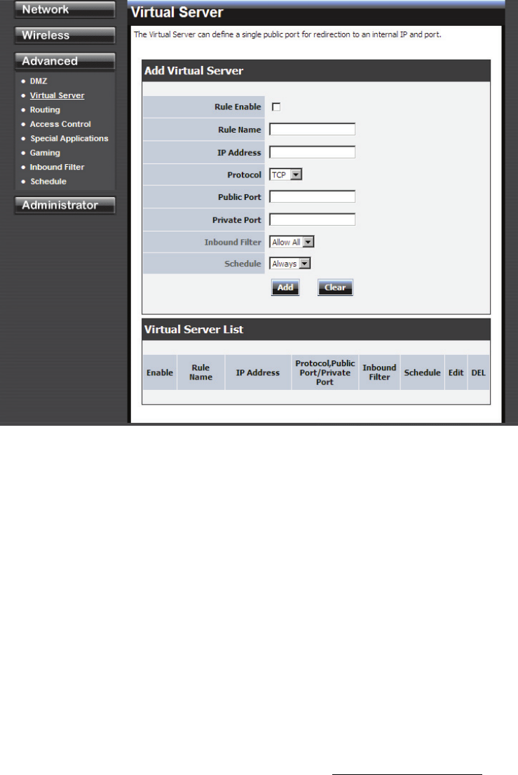
Advanced: Virtual Server
Add/Edit Virtual Server
Enable
Specifies whether the entry will be active or inactive.
Name
Assign a meaningful name to the virtual server, for example Web Server. Several well-known types of
virtual server are available from the "Application Name" drop-down list. Selecting one of these entries
fills some of the remaining parameters with standard values for that type of server.
IP Address
The IP address of the system on your internal network that will provide the virtual service, for example
192.168.0.50. You can select a computer from the list of DHCP clients in the "Computer Name"
drop-down menu, or you can manually enter the IP address of the server computer.
Protocol
Select the protocol used by the service. The common choices -- UDP, TCP, and both UDP and TCP --
can be selected from the drop-down menu. To specify any other protocol, select "Other" from the list,
then enter the corresponding protocol number (as assigned by the IANA) in the Protocol box.
Private Port
The port that will be used on your internal network.
Public Port
32
The port that will be accessed from the Internet.
Schedule
Select a schedule for when the service will be enabled. If you do not see the schedule you need in the list
of schedules.
Clear
Re-initialize this area of the screen, discarding any changes you have made.
33
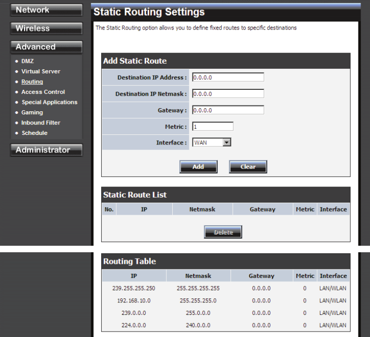
Advanced: Routing
Add/Edit Route
Adds a new route to the IP routing table or edits an existing route.
Destination IP
The IP address of packets that will take this route.
Gateway
Specifies the next hop to be taken if this route is used. A gateway of 0.0.0.0 implies there is no next hop,
and the IP address matched is directly connected to the router on the interface specified: LAN or WAN.
Metric
The route metric is a value from 1 to 16 that indicates the cost of using this route. A value of 1 is the
lowest cost, and 15 is the highest cost. A value of 16 indicates that the route is not reachable from this
router. When trying to reach a particular destination, computers on your network will select the best
route, ignoring unreachable routes.
Interface
Specifies the interface -- LAN or WAN -- that the IP packet must use to transit out of the router, when
this route is used.
Clear
Re-initialize this area of the screen, discarding any changes you have made.
34
Routes List
The section shows the current routing table entries. Certain required routes are predefined and cannot be
changed. Routes that you add can be changed by clicking the Edit icon or can be deleted by clicking the
Delete icon. When you click the Edit icon, the item is highlighted, and the "Edit Route" section is
activated for editing. Click the Enable checkbox at the left to directly activate or de-activate the entry.
35
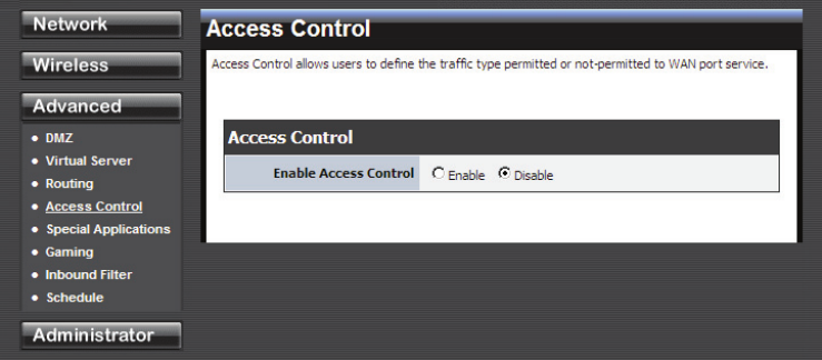
Advanced: Access Control
Enable
By default, the Access Control feature is disabled. If you need Access Control, check this option.
Note: When Access Control is disabled, every device on the LAN has unrestricted access to the Internet.
However, if you enable Access Control, Internet access is restricted for those devices that have an
Access Control Policy configured for them. All other devices have unrestricted access to the Internet.
36
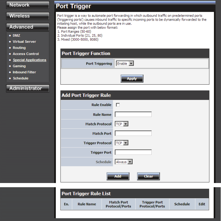
Advanced: Special Applications
Add/Edit Port Trigger Rule
Enable
Specifies whether the entry will be active or inactive.
Name
Enter a name for the Special Application Rule, for example Game App, which will help you identify the
rule in the future. Alternatively, you can select from the Application list of common applications.
Protocol
Select the protocol used by the service. The common choices -- UDP, TCP, and both UDP and TCP --
can be selected from the drop-down menu.
Trigger Port
Enter the outgoing port range used by your application (for example 6500-6700).
Schedule
Select a schedule for when this rule is in effect.
Clear
37
Re-initialize this area of the screen, discarding any changes you have made.
Port Trigger Rule List
This is a list of the defined application rules. Click the Enable checkbox at the left to directly activate or
de-activate the entry. An entry can be changed by clicking the Edit icon or can be deleted by clicking the
Delete icon.
38
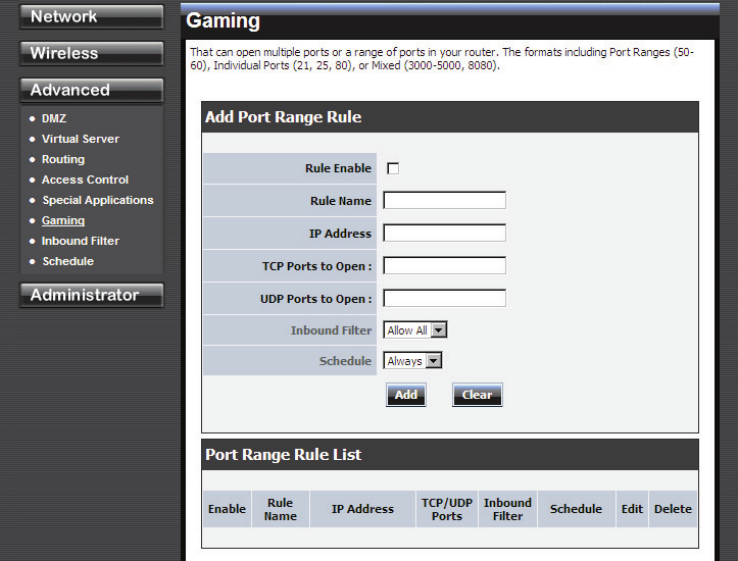
Advanced: Gaming
Add/Edit Port Range Rule
Use this section to add a Port Range Rule to the following list or to edit a rule already in the list.
Rule Enable
Specifies whether the entry will be active or inactive.
Rule Name
Give the rule a name that is meaningful to you, for example Game Server. You can also select from a
list of popular games, and many of the remaining configuration values will be filled in accordingly.
However, you should check whether the port values have changed since this list was created, and you
must fill in the IP address field.
IP Address
Enter the local network IP address of the system hosting the server, for example 192.168.0.50. You can
select a computer from the list of DHCP clients in the "Computer Name" drop-down menu, or you can
manually enter the IP address of the server computer.
TCP Ports to Open
Enter the TCP ports to open (for example 6159-6180, 99).
UDP Ports to Open
Enter the UDP ports to open (for example 6159-6180, 99).
Inbound Filter
Select a filter that controls access as needed for this rule.
39
Schedule
Select a schedule for the times when this rule is in effect.
Clear
Re-initialize this area of the screen, discarding any changes you have made.
Port Range Rule List
This is a list of the defined Port Range Rules. Click the Enable checkbox at the left to directly activate or
de-activate the entry. An entry can be changed by clicking the Edit icon or can be deleted by clicking the
Delete icon. When you click the Edit icon, the item is highlighted, and the "Edit Port Forwarding Rule"
section is activated for editing.
40
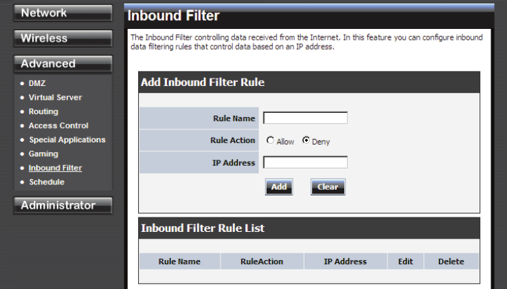
Advanced: Inbound Filter
Add/Edit Inbound Filter Rule
Here you can add entries to the Inbound Filter Rules List below, or edit existing entries.
Name
Enter a name for the rule that is meaningful to you.
Action
The rule can either Allow or Deny messages.
Remote IP Range
Define the ranges of Internet addresses this rule applies to. For a single IP address, enter the same
address in both the Start and End boxes. Up to eight ranges can be entered. The Enable checkbox
allows you to turn on or off specific entries in the list of ranges.
Clear
Re-initialize this area of the screen, discarding any changes you have made.
Inbound Filter Rules List
The section lists the current Inbound Filter Rules. An entry can be changed by clicking the Edit icon or
can be deleted by clicking the Delete icon. When you click the Edit icon, the item is highlighted, and the
"Edit Inbound Filter Rule" section is activated for editing.
In addition to the filters listed here, two predefined filters are available wherever inbound filters can be
applied:
Allow All
Permit any WAN user to access the related capability.
Deny All
Prevent all WAN users from accessing the related capability. (LAN users are not affected by Inbound
Filter Rules.)
41
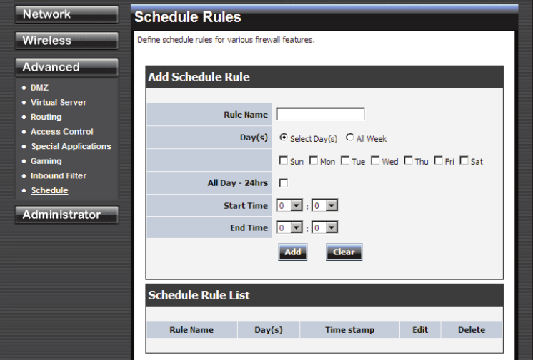
Advanced: Schedule
Add/Edit Schedule Rule
In this section you can add entries to the Schedule Rules List below or edit existing entries.
Name
Give the schedule a name that is meaningful to you, such as "Weekday rule".
Day(s)
Place a checkmark in the boxes for the desired days or select the All Week radio button to select all
seven days of the week.
All Day - 24 hrs
Select this option if you want this schedule in effect all day for the selected day(s).
Start Time
If you don't use the All Day option, then you enter the time here. The start time is entered in two fields.
The first box is for the hour and the second box is for the minute. Email events are normally triggered
only by the start time.
End Time
The end time is entered in the same format as the start time. The hour in the first box and the minutes in
the second box. The end time is used for most other rules, but is not normally used for email events.
Clear
Re-initialize this area of the screen, discarding any changes you have made.
Schedule Rules List
42
This section shows the currently defined Schedule Rules. An entry can be changed by clicking the Edit
icon or can be deleted by clicking the Delete icon. When you click the Edit icon, the item is highlighted,
and the "Edit Schedule Rule" section is activated for editing.
43
Administrator
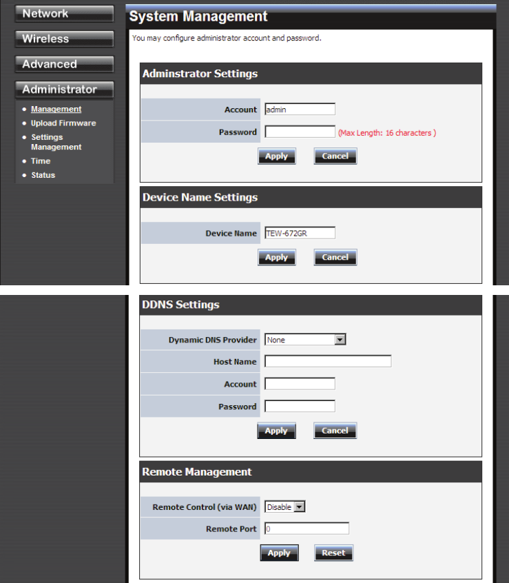
Administrator: Management
Admin Password
Enter a password for the user "admin", who will have full access to the Web-based management
interface.
Device Name
The name of the router can be changed here.
Enable Dynamic DNS
Enable this option only if you have purchased your own domain name and registered with a dynamic
DNS service provider. The following paramters are displayed when the option is enabled.
Dynamic DNS Provider
44
Select a dynamic DNS service provider from the pull-down list.
Host Name
Enter your host name, fully qualified; for example: myhost.mydomain.net.
Account
Enter the account provided by your service provider. If the Dynamic DNS provider supplies only a key,
enter that key in all three fields.
Password
Enter the password provided by your service provider. If the Dynamic DNS provider supplies only a key,
enter that key in all three fields.
45
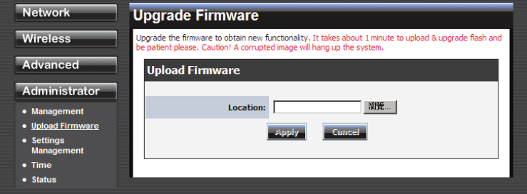
Administrator: Upload Firmware
Upload Firmware
Upload Firmware
Once you have a firmware update on your computer, use this option to browse for the file and then
upload the information into the router.
46
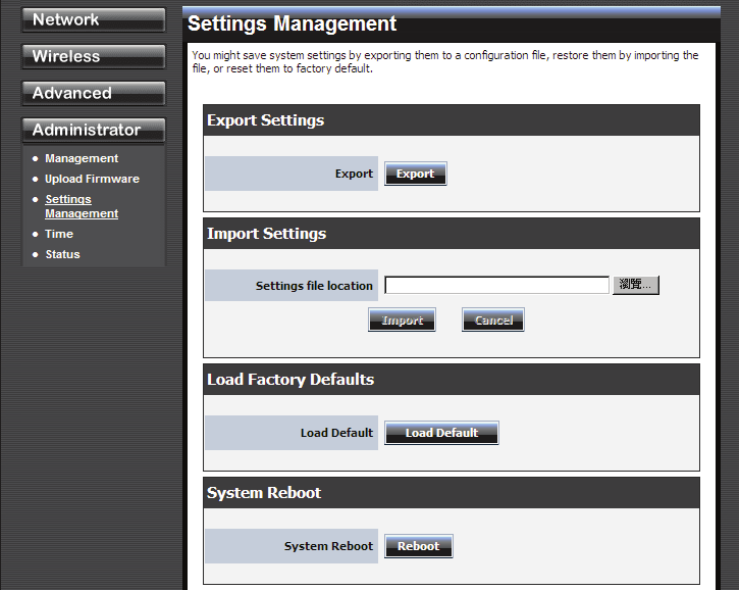
Administrator: Setting Management
Export Settings
This option allows you to export and then save the router's configuration to a file on your computer. Be
sure to save the configuration before performing a firmware upgrade.
Import Settings
Use this option to restore previously saved router configuration settings.
Load Factory Defaults
This option restores all configuration settings back to the settings that were in effect at the time the router
was shipped from the factory. Any settings that have not been saved will be lost. If you want to save your
router configuration settings, use the Export Settings option above.
System Reboot
This restarts the router. It is useful for restarting when you are not near the device.
47
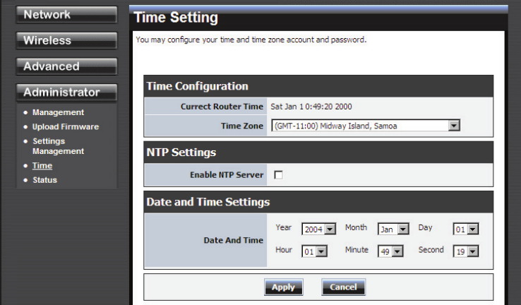
Administrator: Time
Time Configuration
Current Router Time
Displays the time currently maintained by the router. If this is not correct, use the following options to
configure the time correctly.
Time Zone
Select your local time zone from pull down menu.
Automatic Time Configuration
Enable NTP Server
Select this option if you want to synchronize the router's clock to a Network Time Server over the
Internet. If you are using schedules or logs, this is the best way to ensure that the schedules and logs are
kept accurate.
Note that, even when NTP Server is enabled, you must still choose a time zone and set the daylight
saving parameters.
NTP Server Used
Select a Network Time Server for synchronization. You can type in the address of a time server or select
one from the list. If you have trouble using one server, select another.
Set the Date and Time Manually
If you do not have the NTP Server option in effect, you can either manually set the time for your router
here.
48
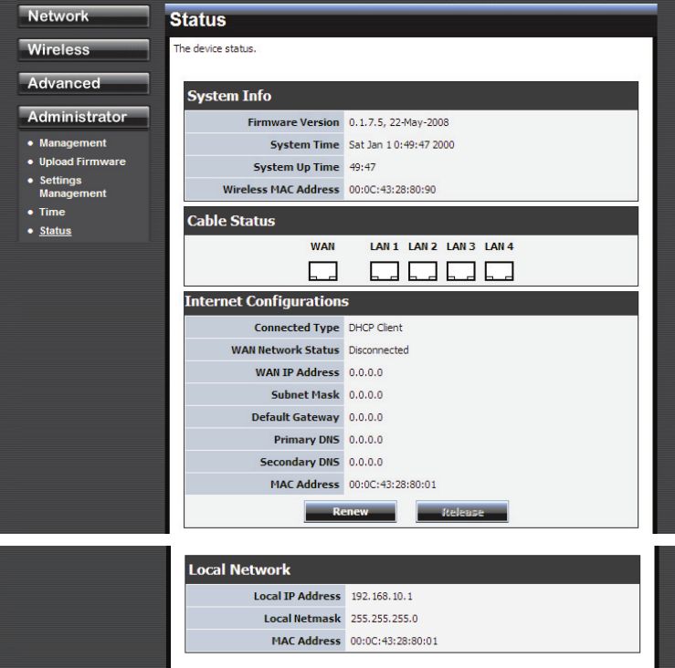
Administrator: Status