TRENDNET TEW673GRU 300Mbps Concurrent Dual Band Wireless N Gigabit Router User Manual
TRENDNET, Inc. 300Mbps Concurrent Dual Band Wireless N Gigabit Router
UserManual.wiki
>
TRENDNET
>
TEW673GRU User Manual
>
Manual Part 2
Contents
1.
Manual Part 1
2.
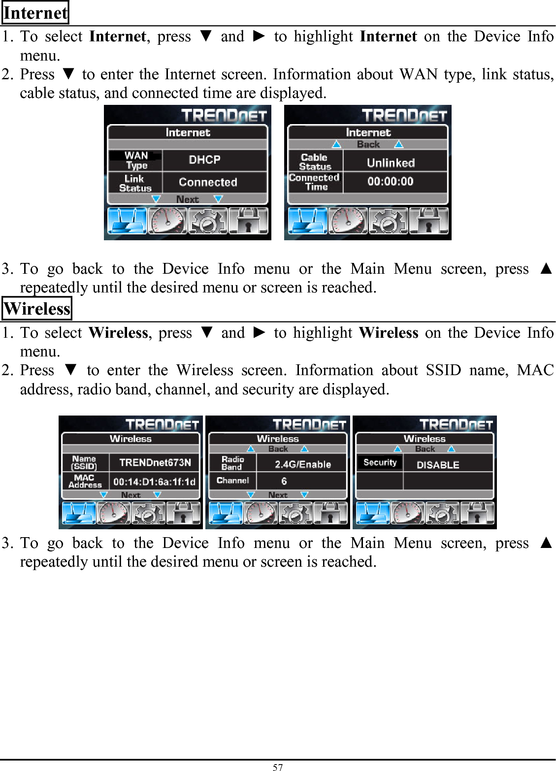
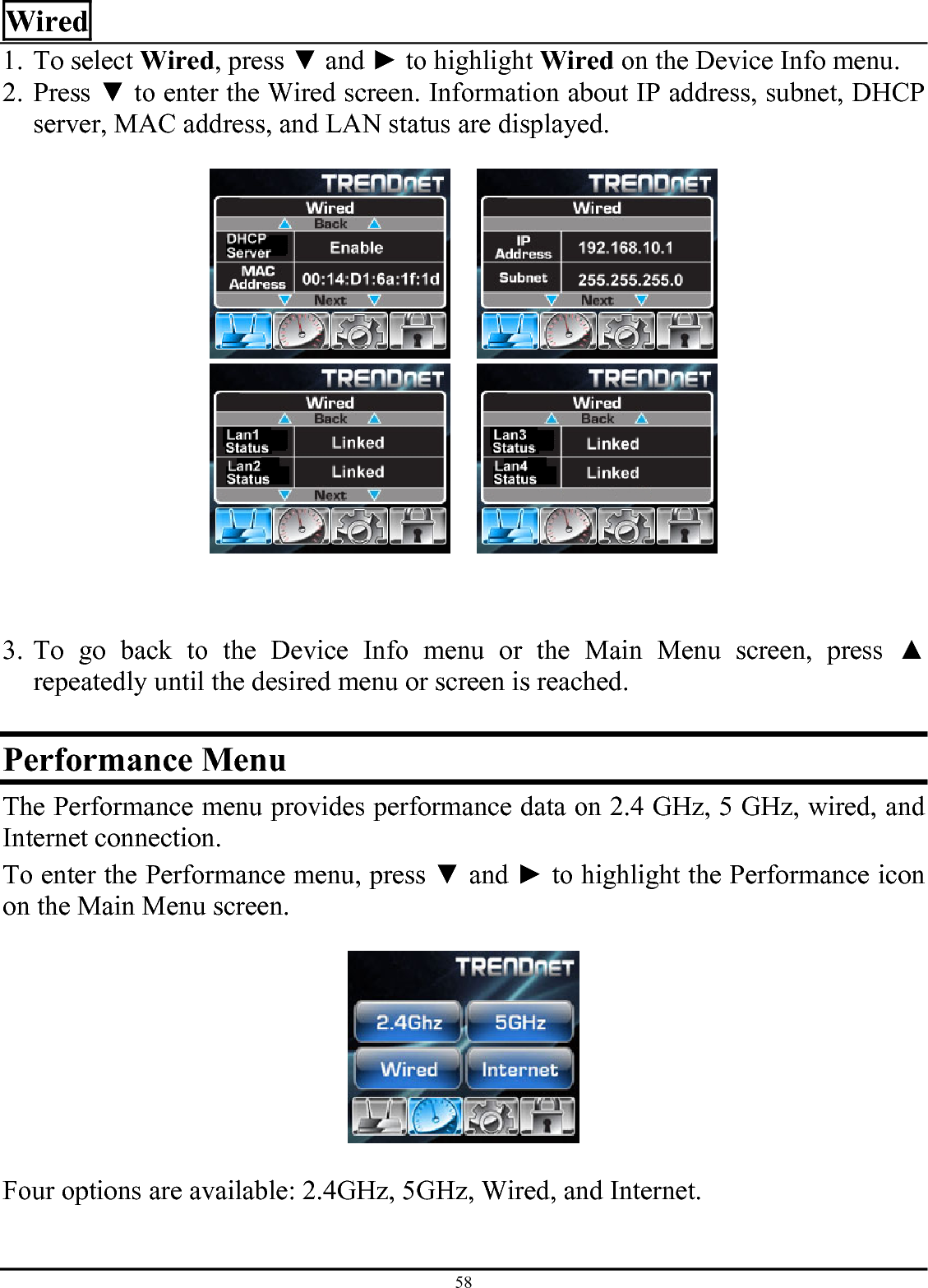
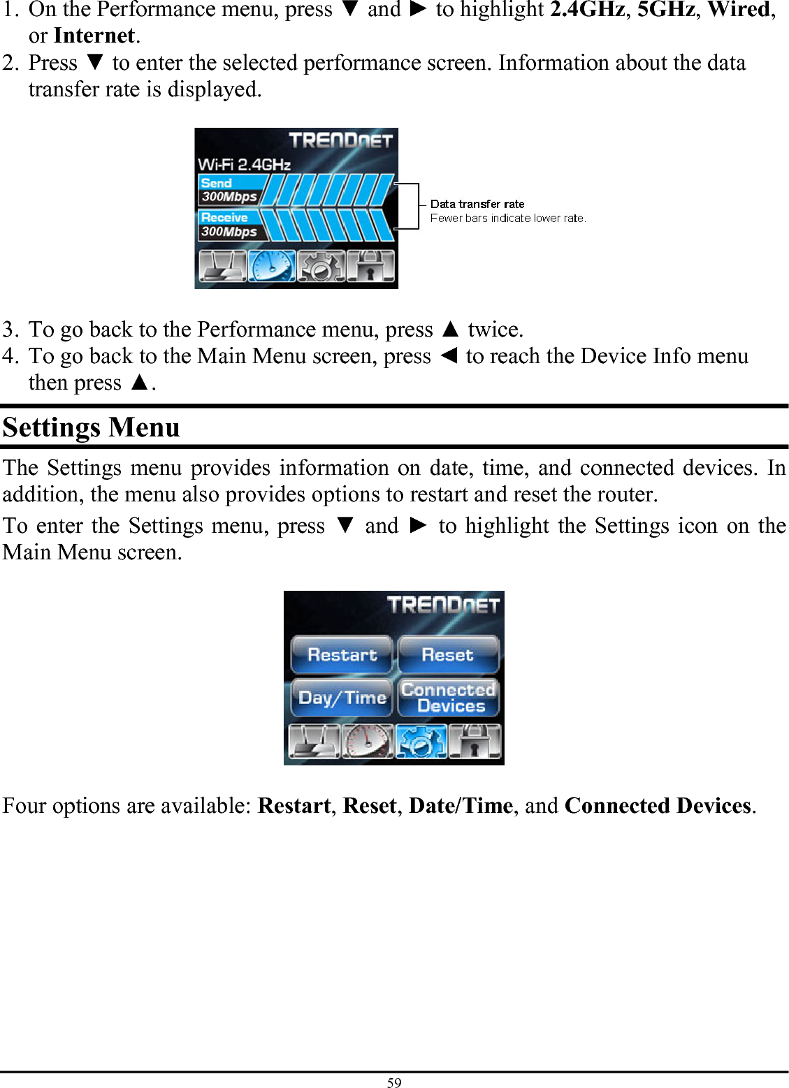
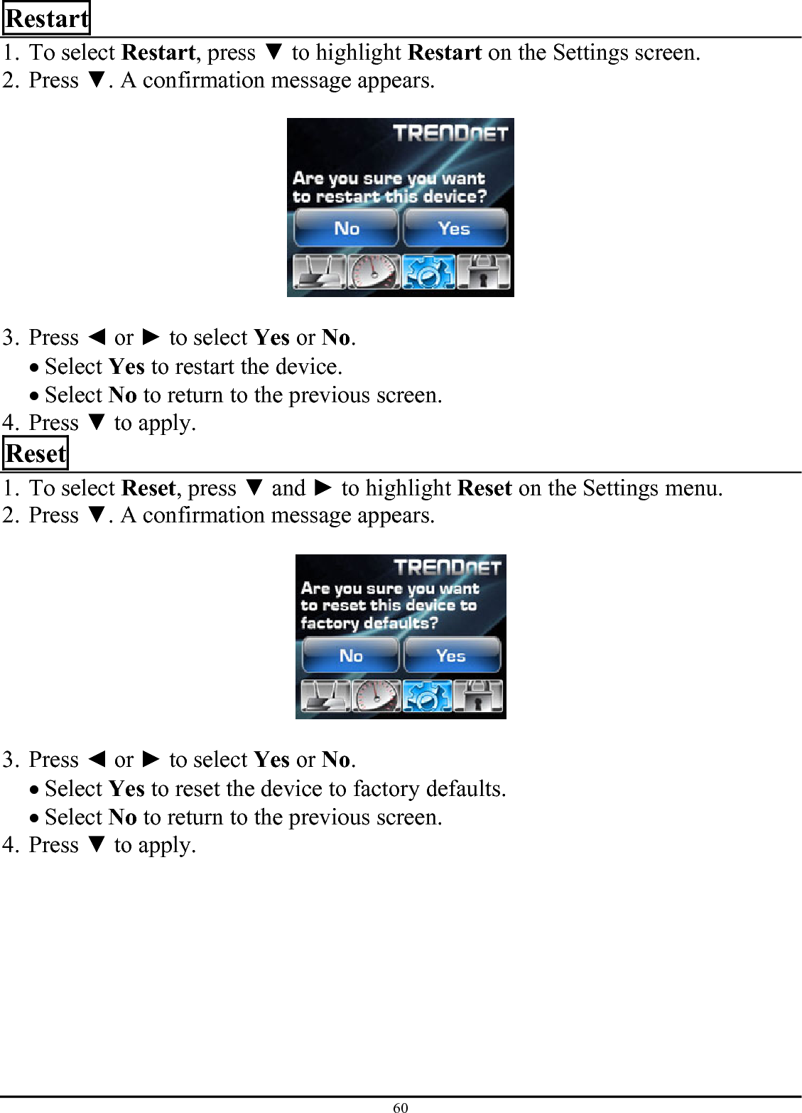
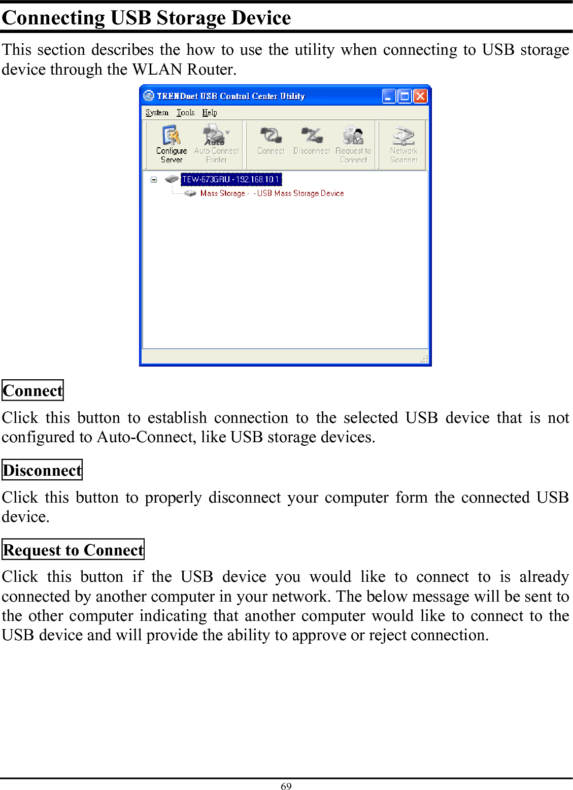
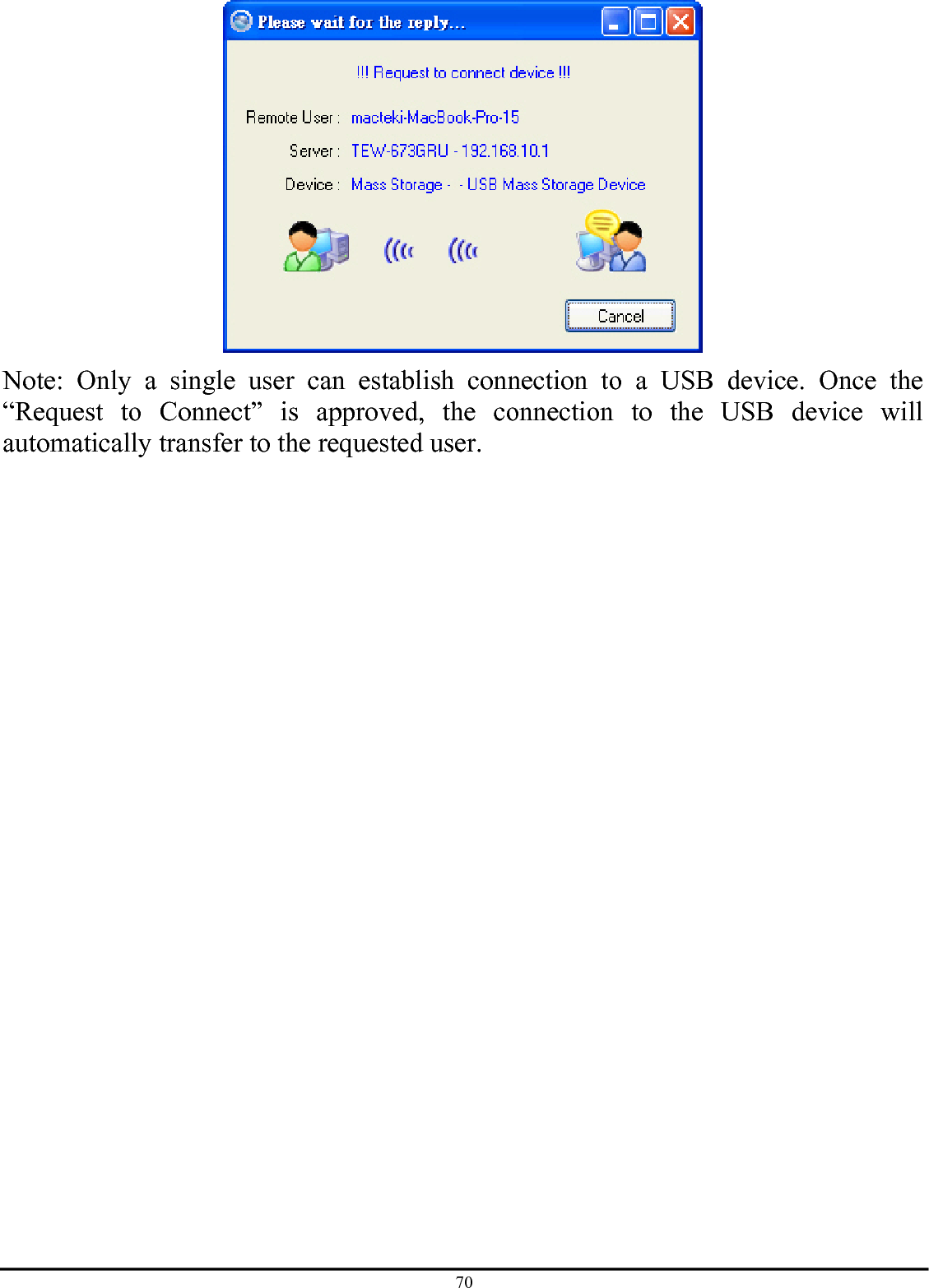
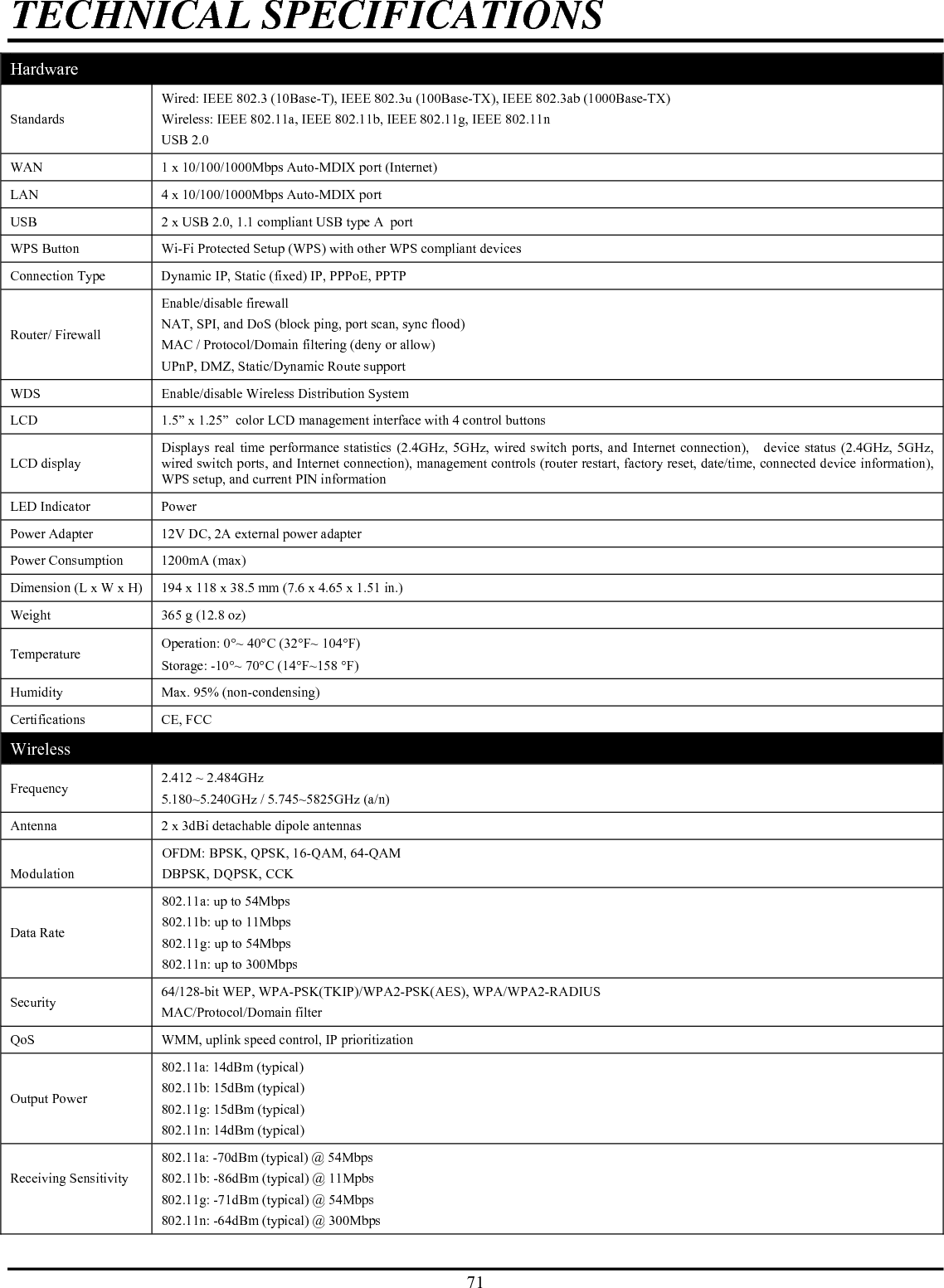
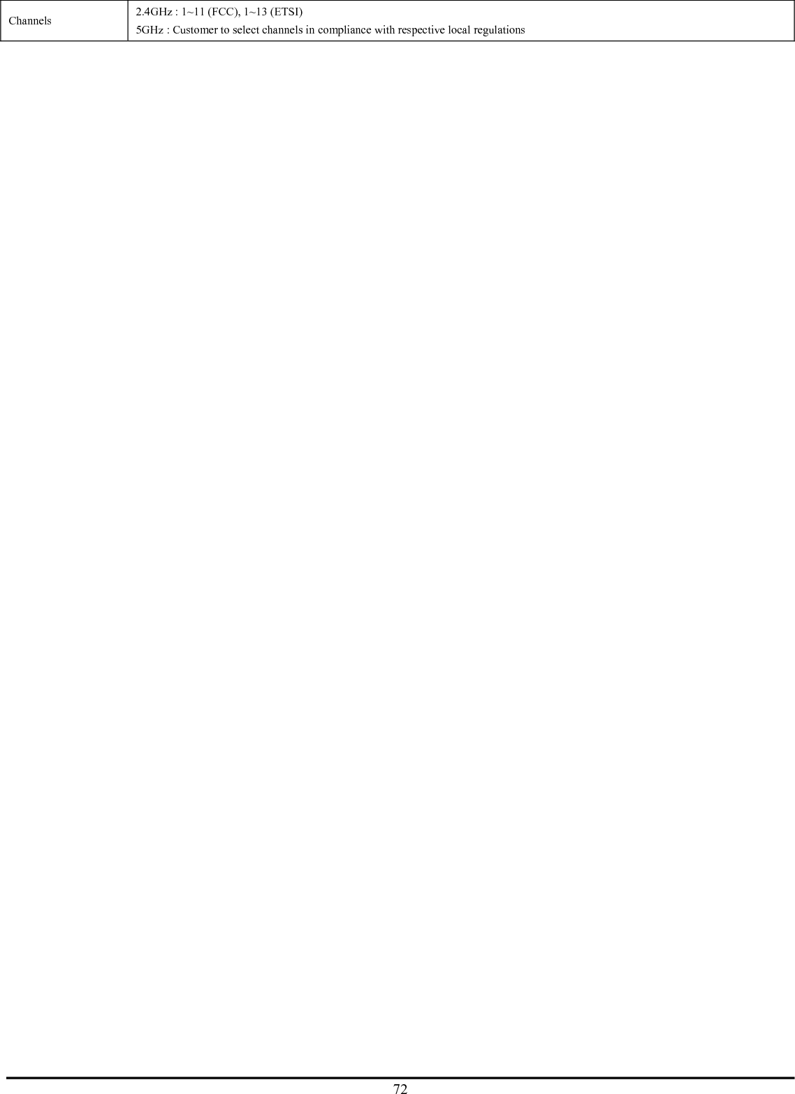
Manual Part 2
Manual Part 2
Navigation menu
Upload a User Manual
Namespaces
Wiki Guide
HTML
PDF
Info
Views
User Manual
Discussion / Help
Navigation