TRENDNET TEW713BR 150Mbps Compact Single Port Wireless N Router User Manual User s manual TEW 713x
TRENDNET, Inc. 150Mbps Compact Single Port Wireless N Router User s manual TEW 713x
UserManual.wiki
>
TRENDNET
>
TEW713BR User Manual
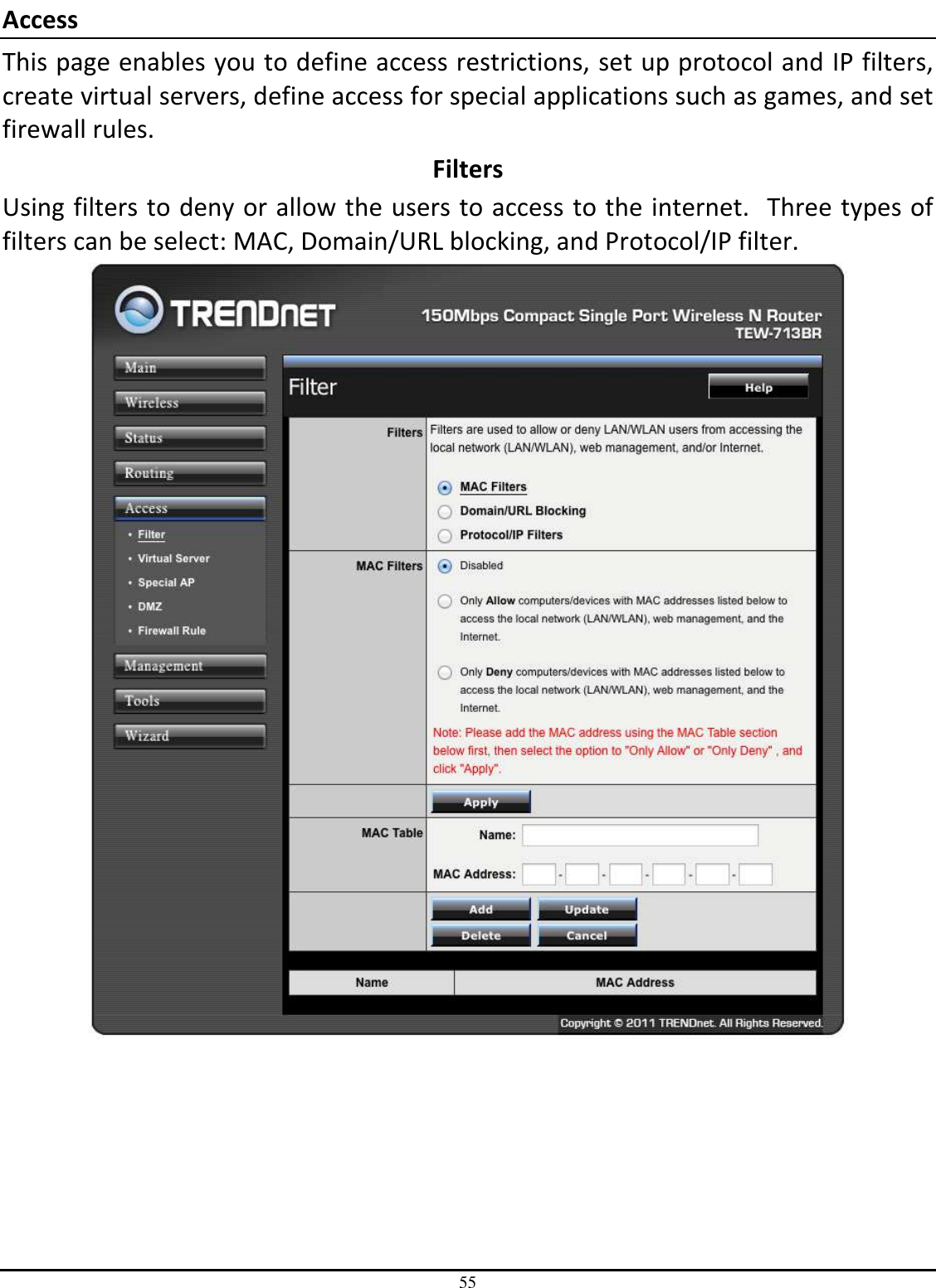
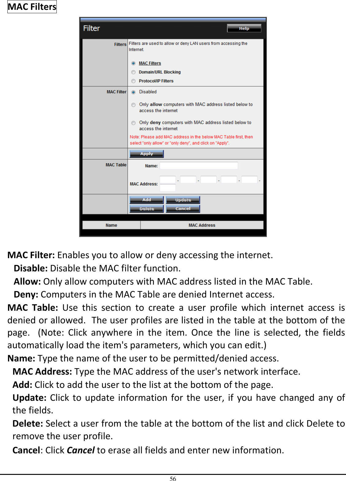
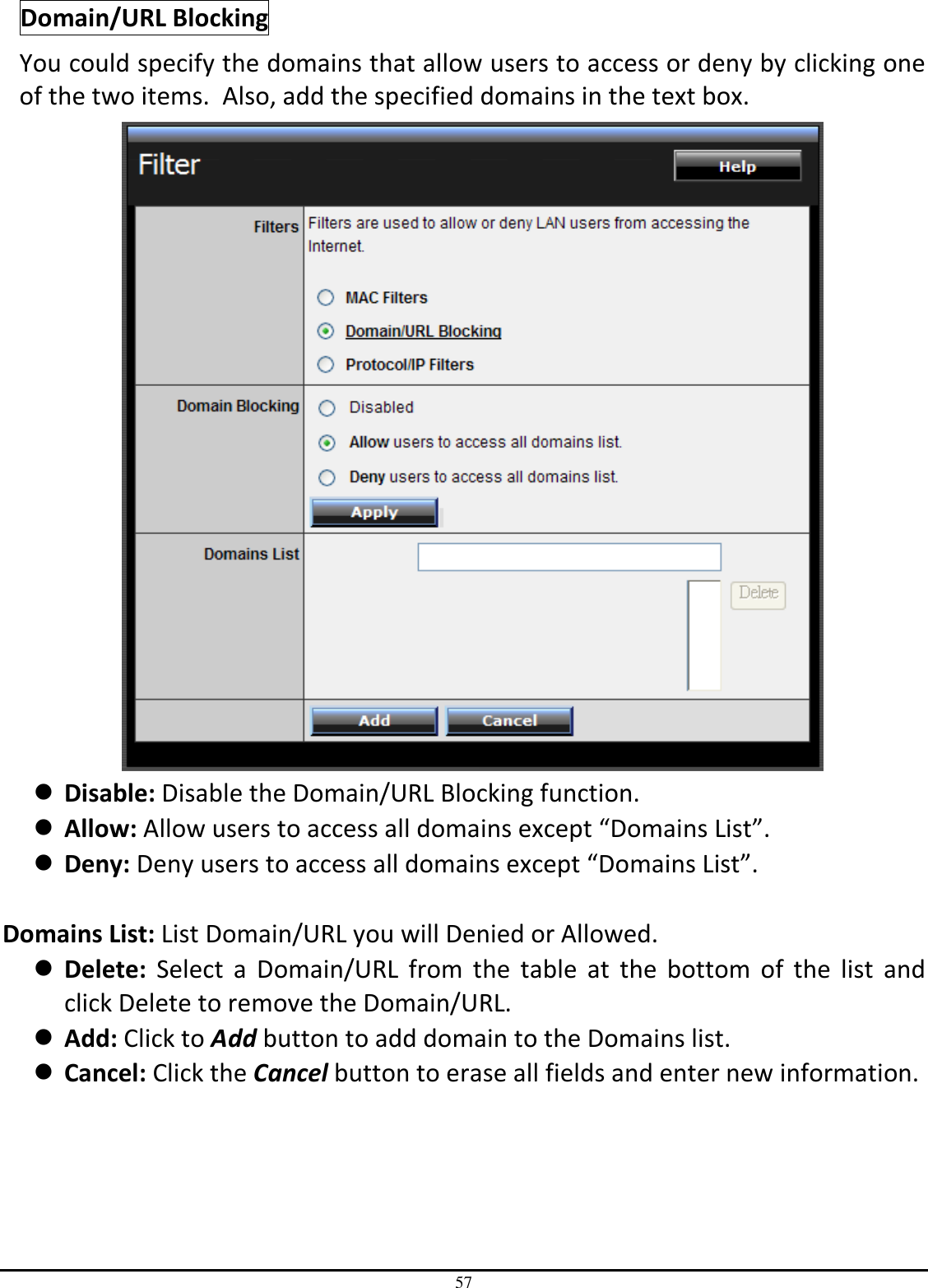
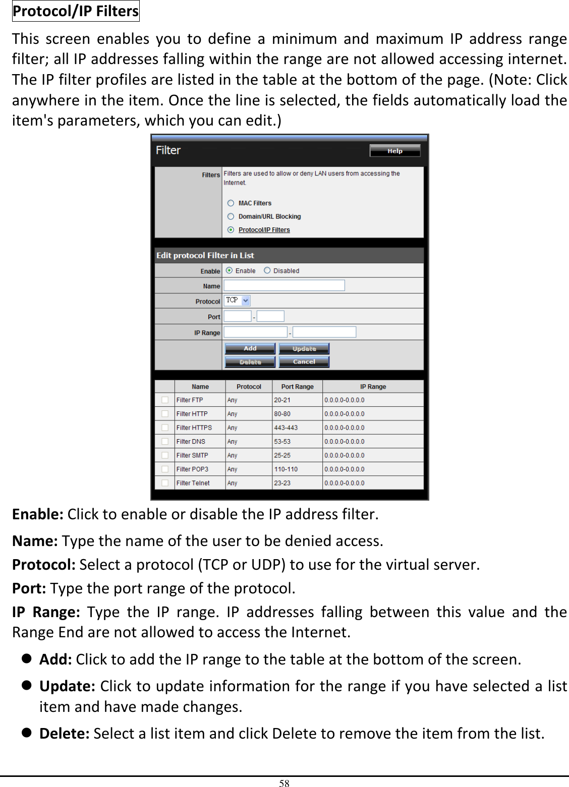
User Manual
Navigation menu
Upload a User Manual
Namespaces
Wiki Guide
HTML
PDF
Info
Views
User Manual
Discussion / Help
Navigation
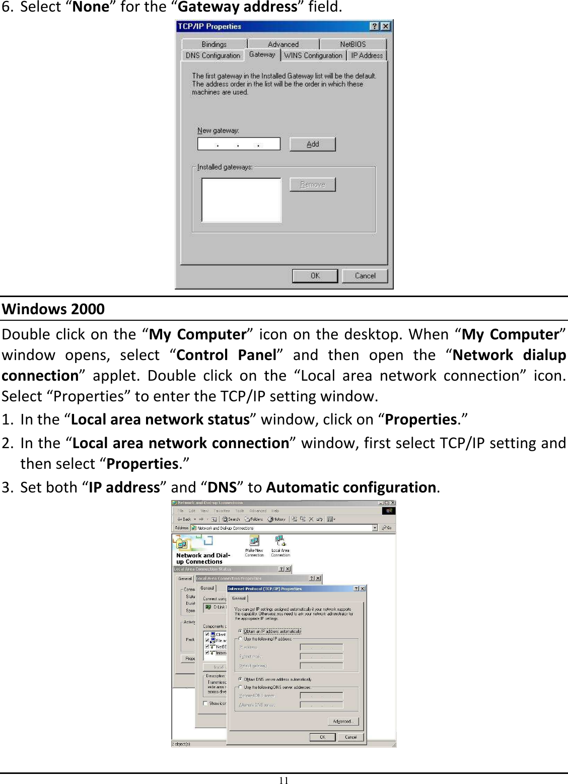
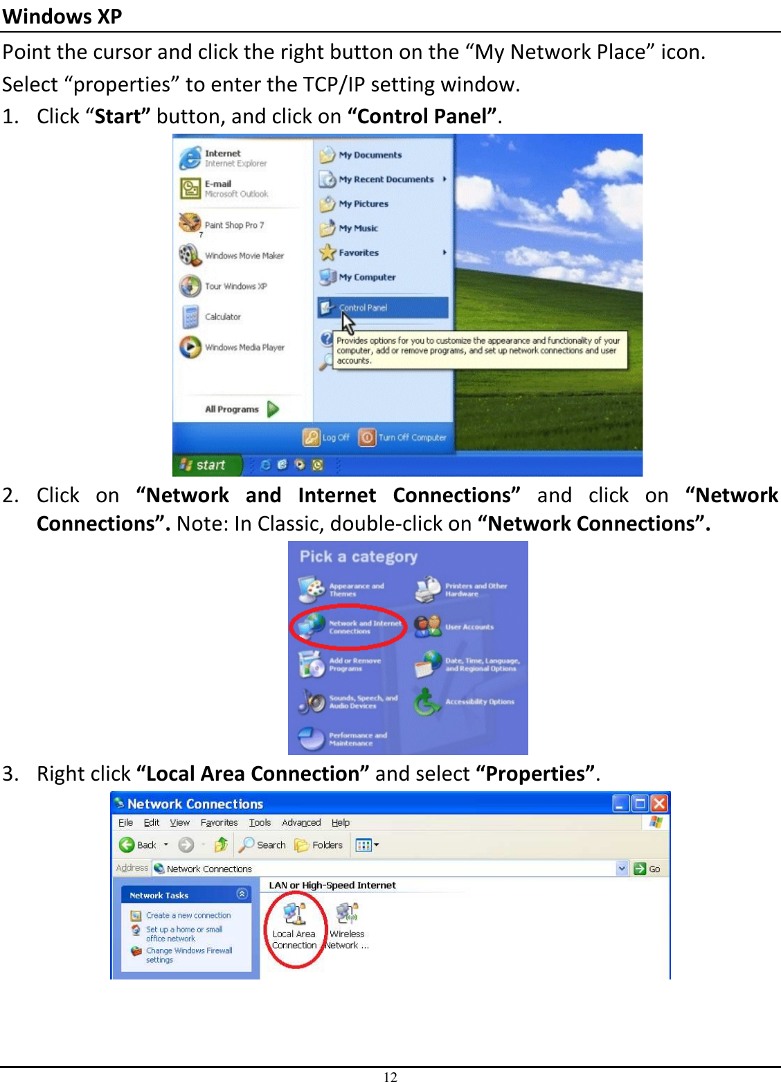
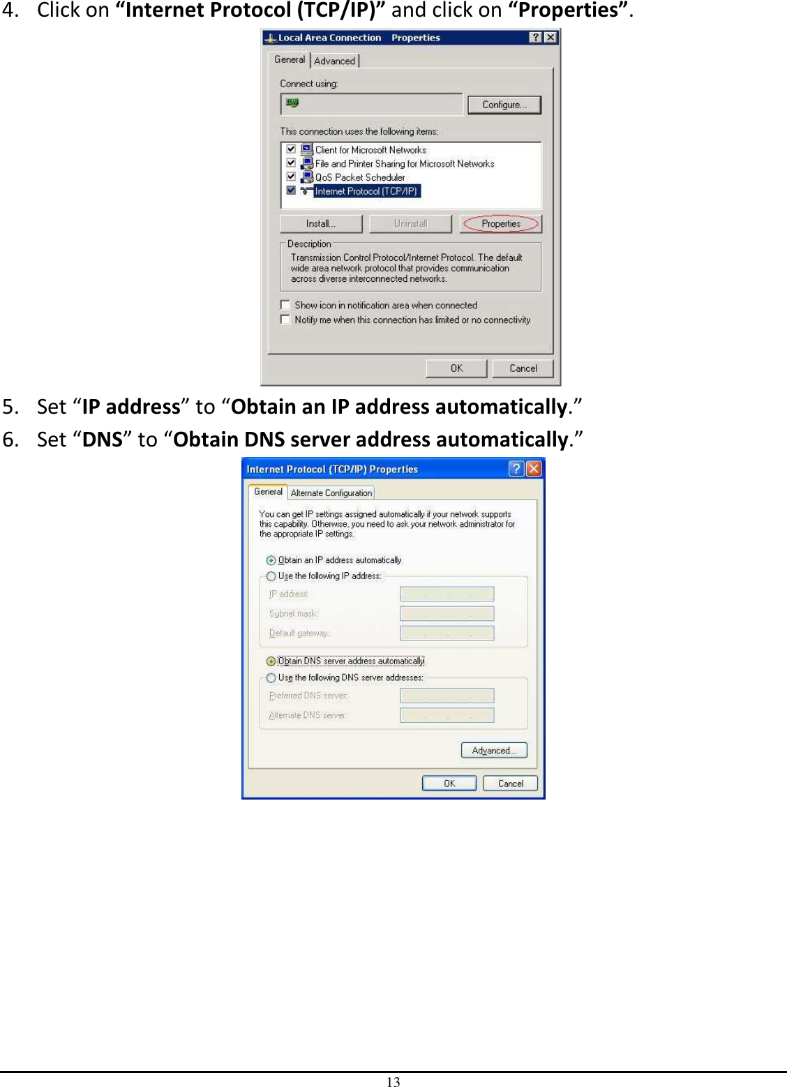
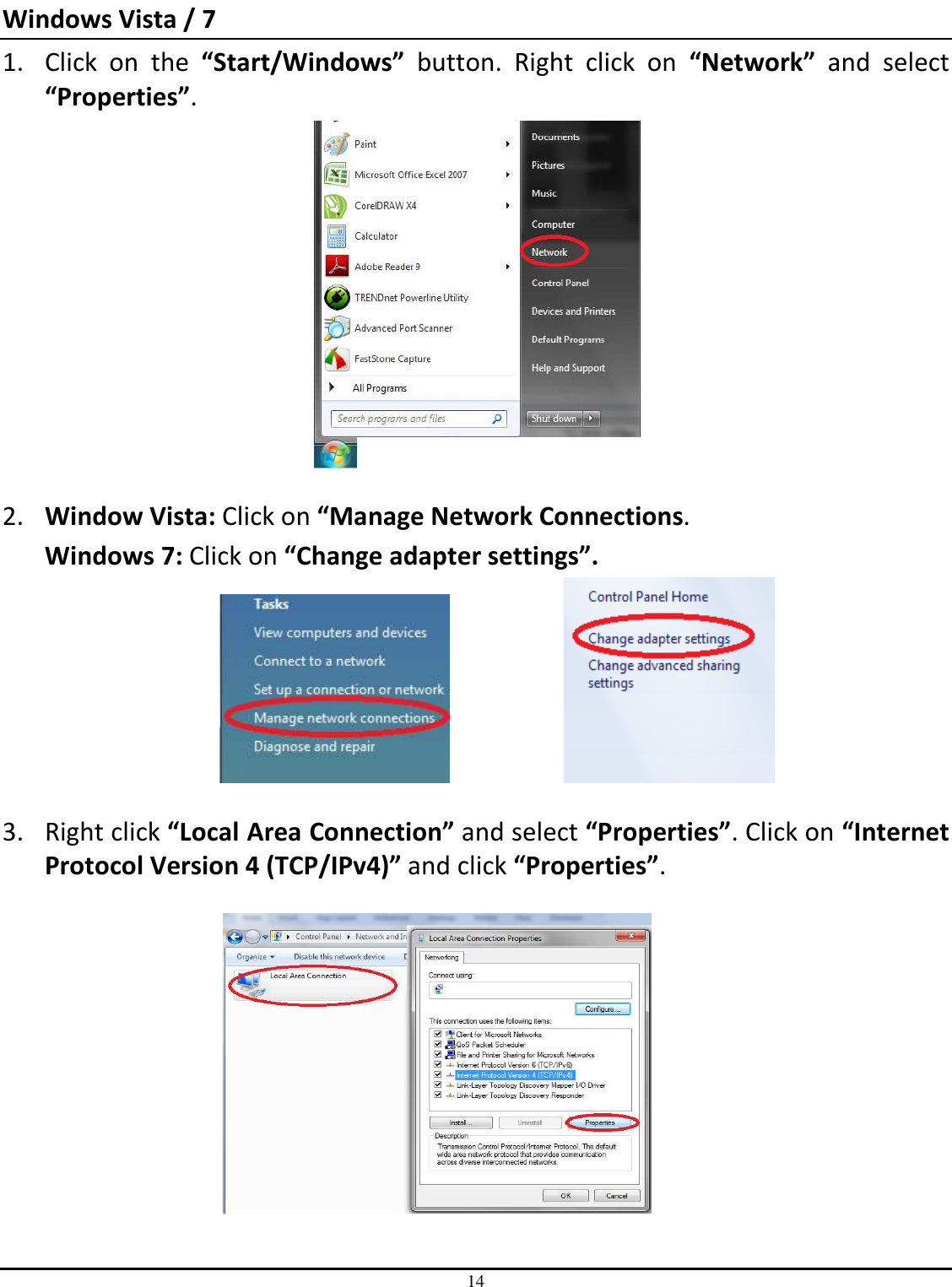
![iii EN 300 328 V1.7.1 (2006-10) Electromagnetic compatibility and Radio spectrum Matters (ERM); Wideband transmission systems; Data transmission equipment operating in the 2,4 GHz ISM band and using wide band modulation techniques; Harmonized EN covering essential requirements under article 3.2 of the R&TTE Directive EN 301 489-1 V1.8.1 (2008-04) Electromagnetic compatibility and Radio Spectrum Matters (ERM); ElectroMagnetic Compatibility (EMC) standard for radio equipment and services; Part 1: Common technical requirements EN 301 489-17 V2.1.1(2009-05) Electromagnetic compatibility and Radio spectrum Matters (ERM); ElectroMagnetic Compatibility (EMC) standard for radio equipment and services; Part 17: Specific conditions for 2,4 GHz wideband transmission systems and 5 GHz high performance RLAN equipment This device is a 2.4 GHz wideband transmission system (transceiver), intended for use in all EU member states and EFTA countries, except in France and Italy where restrictive use applies. In Italy the end-user should apply for a license at the national spectrum authorities in order to obtain authorization to use the device for setting up outdoor radio links and/or for supplying public access to telecommunications and/or network services. This device may not be used for setting up outdoor radio links in France and in some areas the RF output power may be limited to 10 mW EIRP in the frequency range of 2454 – 2483.5 MHz. For detailed information the end-user should contact the national spectrum authority in France. Česky [Czech] TRENDnet tímto prohlašuje, že tento TEW-713BR je ve shodě se základními požadavky a dalšími příslušnými ustanoveními směrnice 1999/5/ES. Dansk [Danish] Undertegnede TRENDnet erklærer herved, at følgende udstyr TEW-713BR overholder de væsentlige krav og øvrige relevante krav i direktiv 1999/5/EF. Deutsch [German] Hiermit erklärt TRENDnet, dass sich das Gerät TEW-713BR in Übereinstimmung mit den grundlegenden Anforderungen und den übrigen einschlägigen Bestimmungen der Richtlinie 1999/5/EG befindet. Eesti [Estonian] Käesolevaga kinnitab TRENDnet seadme TEW-713BR vastavust direktiivi 1999/5/EÜ põhinõuetele ja nimetatud direktiivist tulenevatele teistele asjakohastele sätetele. English Hereby, TRENDnet, declares that this TEW-713BR is in compliance with the essential requirements and other relevant provisions of Directive 1999/5/EC. Español [Spanish] Por medio de la presente TRENDnet declara que el TEW-713BR cumple con los requisitos esenciales y cualesquiera otras disposiciones aplicables o exigibles de la Directiva 1999/5/CE. Ελληνική [Greek] ΜΕ ΤΗΝ ΠΑΡΟΥΣΑ TRENDnet ΔΗΛΩΝΕΙ ΟΤΙ TEW-713BR ΣΥΜΜΟΡΦΩΝΕΤΑΙ ΠΡΟΣ ΤΙΣ ΟΥΣΙΩΔΕΙΣ ΑΠΑΙΤΗΣΕΙΣ ΚΑΙ ΤΙΣ ΛΟΙΠΕΣ ΣΧΕΤΙΚΕΣ ΔΙΑΤΑΞΕΙΣ ΤΗΣ](https://usermanual.wiki/TRENDNET/TEW713BR/User-Guide-1555983-Page-3.png)
![iv ΟΔΗΓΙΑΣ 1999/5/ΕΚ. Français [French] Par la présente TRENDnet déclare que l'appareil TEW-713BR est conforme aux exigences essentielles et aux autres dispositions pertinentes de la directive 1999/5/CE. Italiano [Italian] Con la presente TRENDnet dichiara che questo TEW-713BR è conforme ai requisiti essenziali ed alle altre disposizioni pertinenti stabilite dalla direttiva 1999/5/CE. Latviski [Latvian] Ar šo TRENDnet deklarē, ka TEW-713BR atbilst Direktīvas 1999/5/EK būtiskajām prasībām un citiem ar to saistītajiem noteikumiem. Lietuvių [Lithuanian] Šiuo TRENDnet deklaruoja, kad šis TEW-713BR atitinka esminius reikalavimus ir kitas 1999/5/EB Direktyvos nuostatas. Nederlands [Dutch] Hierbij verklaart TRENDnet dat het toestel TEW-713BR in overeenstemming is met de essentiële eisen en de andere relevante bepalingen van richtlijn 1999/5/EG. Malti [Maltese] Hawnhekk, TRENDnet, jiddikjara li dan TEW-713BR jikkonforma mal-ħtiġijiet essenzjali u ma provvedimenti oħrajn relevanti li hemm fid-Dirrettiva 1999/5/EC. Magyar [Hungarian] Alulírott, TRENDnet nyilatkozom, hogy a TEW-713BR megfelel a vonatkozó alapvetõ követelményeknek és az 1999/5/EC irányelv egyéb elõírásainak. Polski [Polish] Niniejszym TRENDnet oświadcza, że TEW-713BR jest zgodny z zasadniczymi wymogami oraz pozostałymi stosownymi postanowieniami Dyrektywy 1999/5/EC. Português [Portuguese] TRENDnet declara que este TEW-713BR está conforme com os requisitos essenciais e outras disposições da Directiva 1999/5/CE. Slovensko [Slovenian] TRENDnet izjavlja, da je ta TEW-713BR v skladu z bistvenimi zahtevami in ostalimi relevantnimi določili direktive 1999/5/ES. Slovensky [Slovak] TRENDnet týmto vyhlasuje, že TEW-713BR spĺňa základné požiadavky a všetky príslušné ustanovenia Smernice 1999/5/ES. Suomi [Finnish] TRENDnet vakuuttaa täten että TEW-713BR tyyppinen laite on direktiivin 1999/5/EY oleellisten vaatimusten ja sitä koskevien direktiivin muiden ehtojen mukainen. Svenska [Swedish] Härmed intygar TRENDnet att denna TEW-713BR står I överensstämmelse med de väsentliga egenskapskrav och övriga relevanta bestämmelser som framgår av direktiv 1999/5/EG.](https://usermanual.wiki/TRENDNET/TEW713BR/User-Guide-1555983-Page-4.png)