TRENDNET TEWMP2U Wireless MultiFunction Printer Server User Manual UG TE100 MP1U MP2U TEW MP2U
TRENDNET, INC. Wireless MultiFunction Printer Server UG TE100 MP1U MP2U TEW MP2U
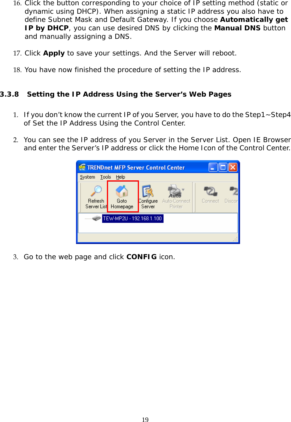
UserManual.wiki
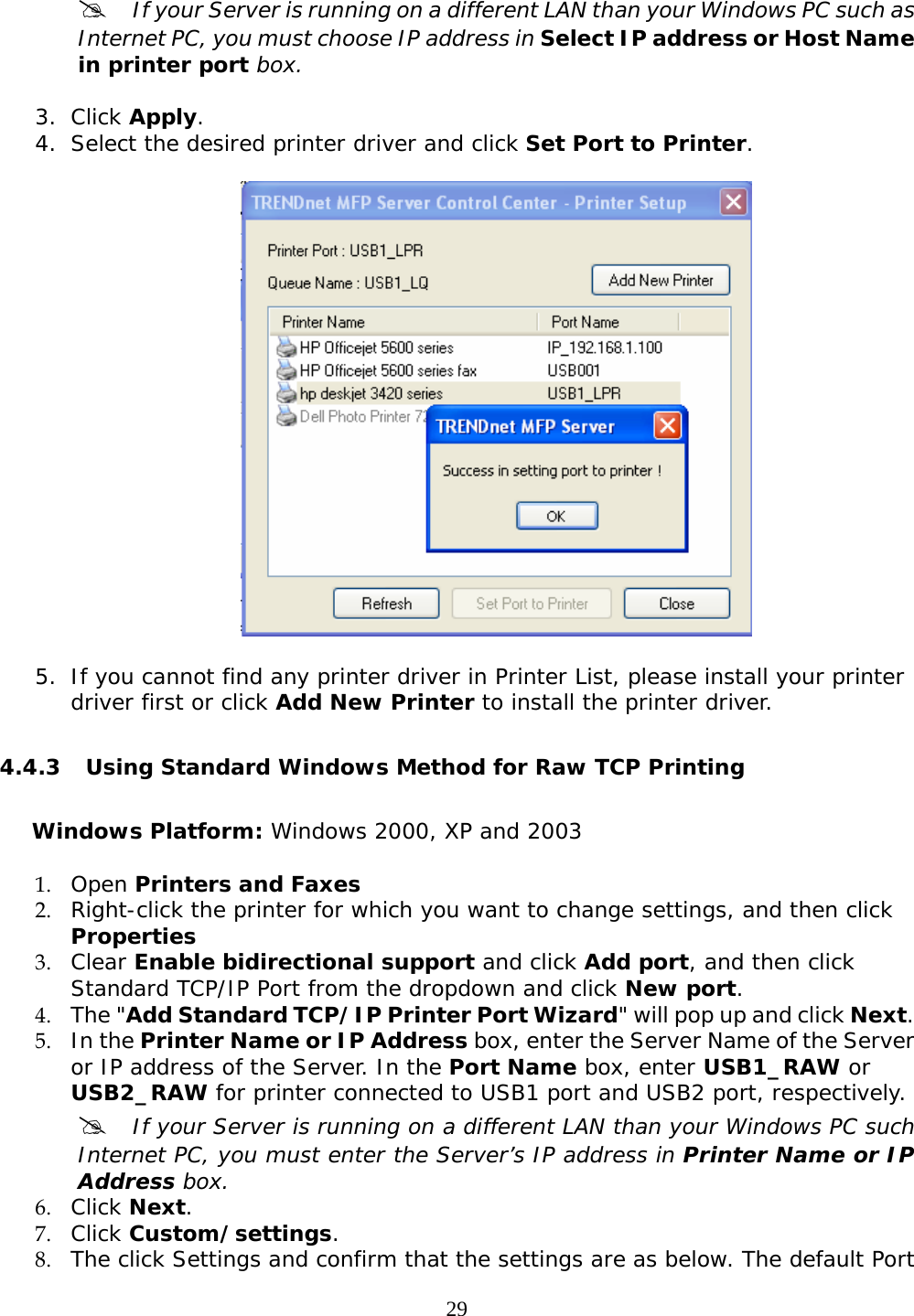
>
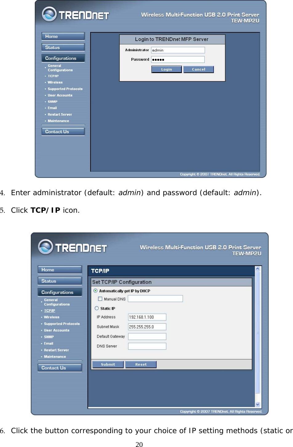
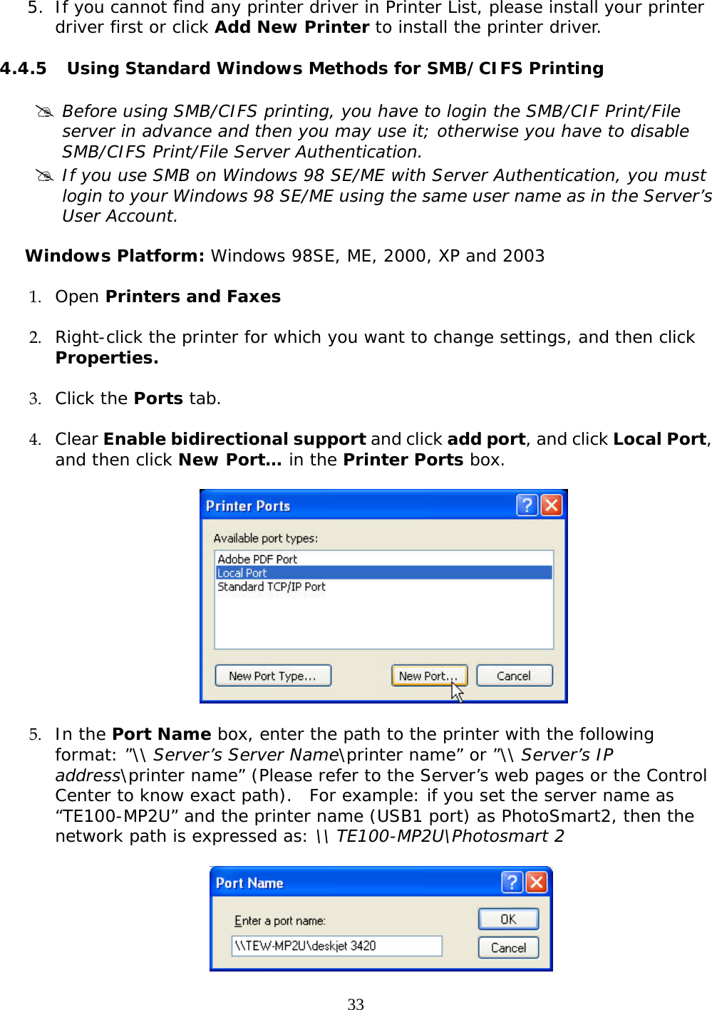
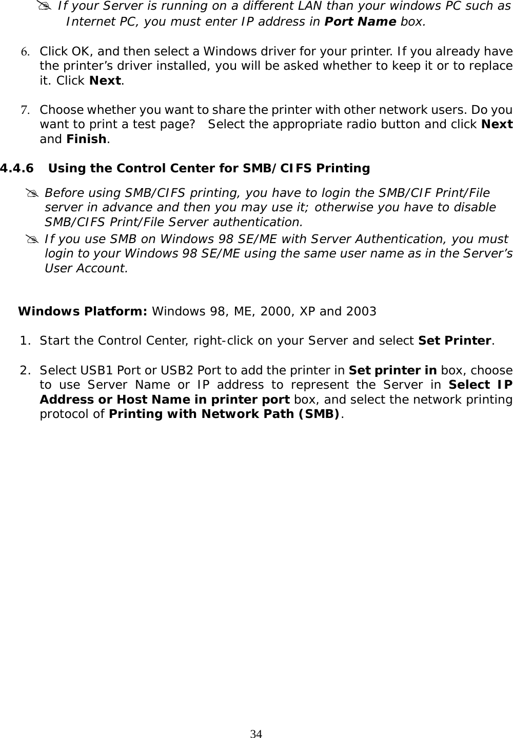
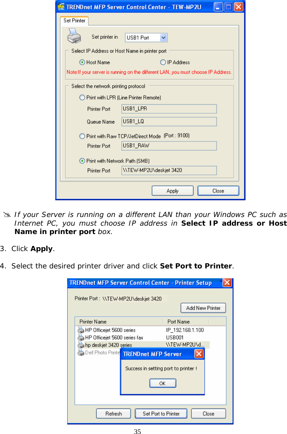
TRENDNET
>
TEWMP2U User Manual
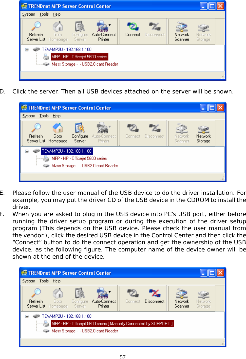
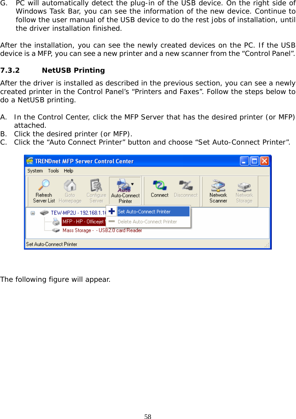
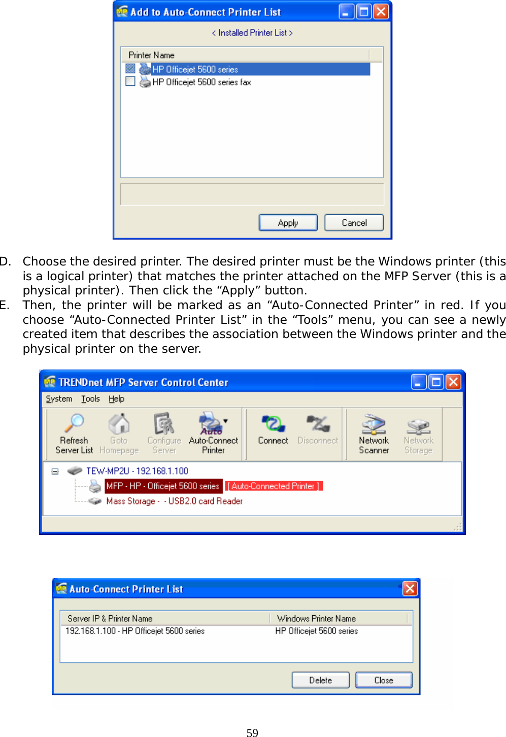
Manual
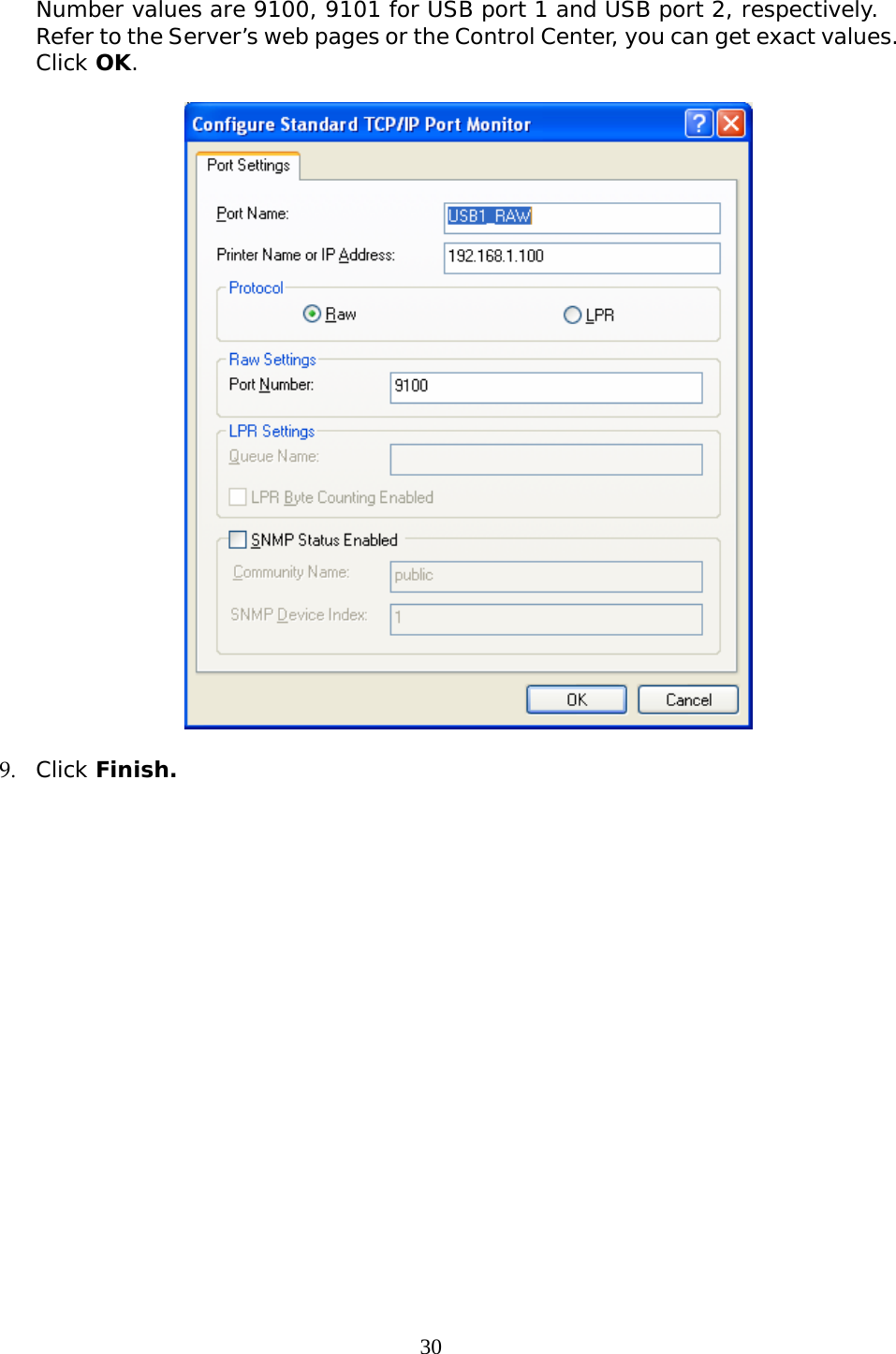
Navigation menu
Upload a User Manual
Namespaces
Wiki Guide
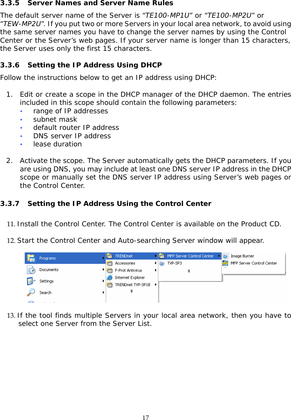
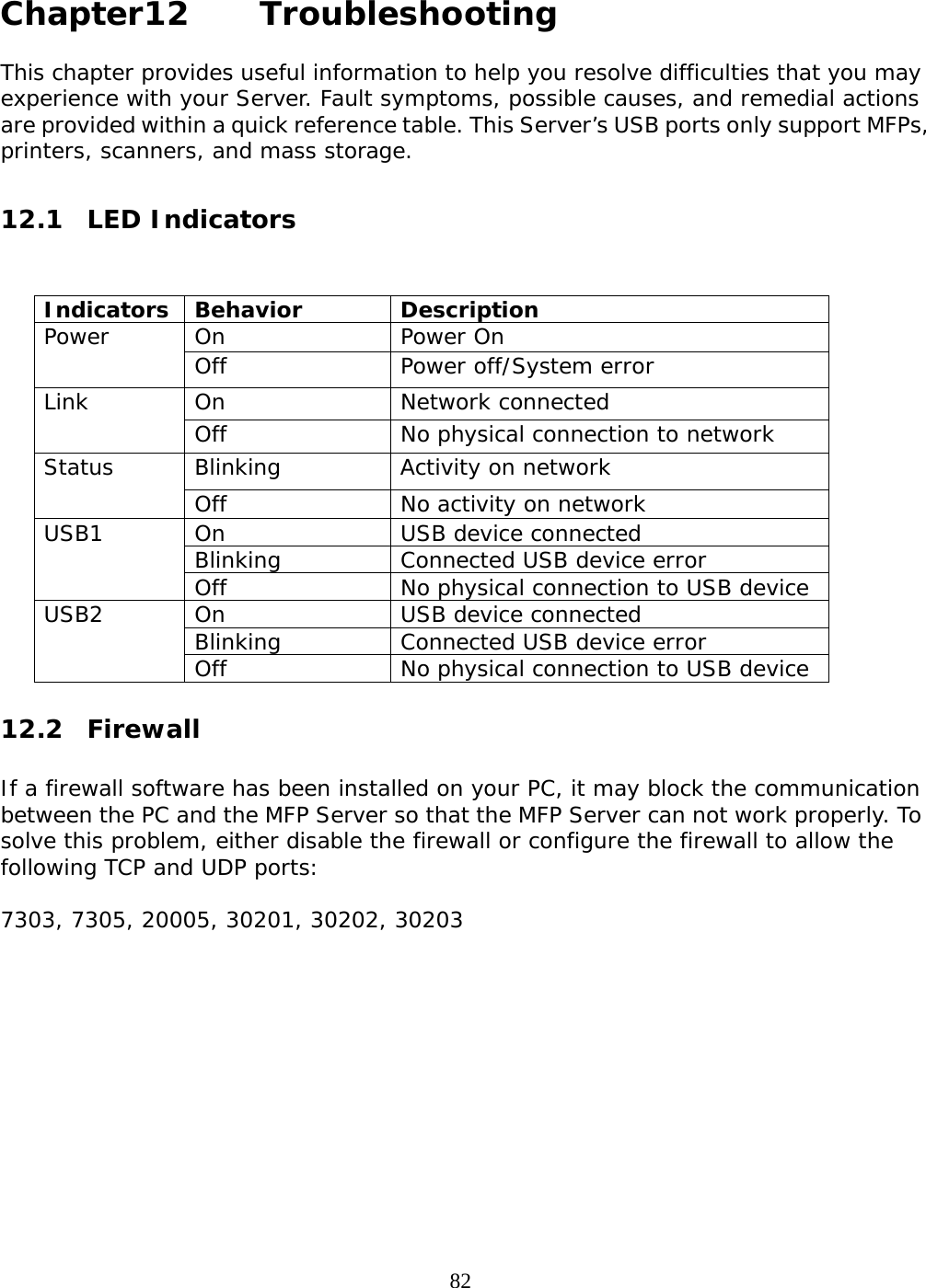
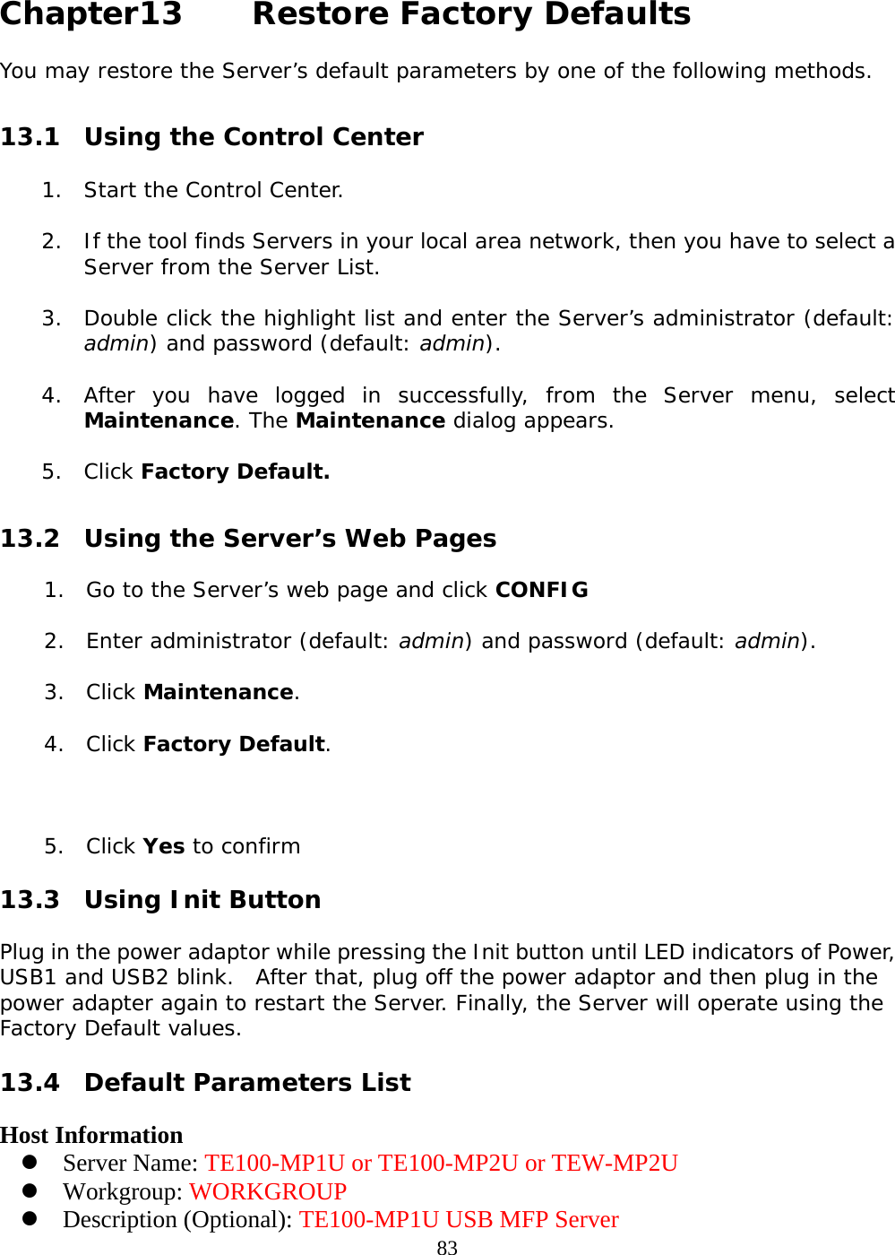
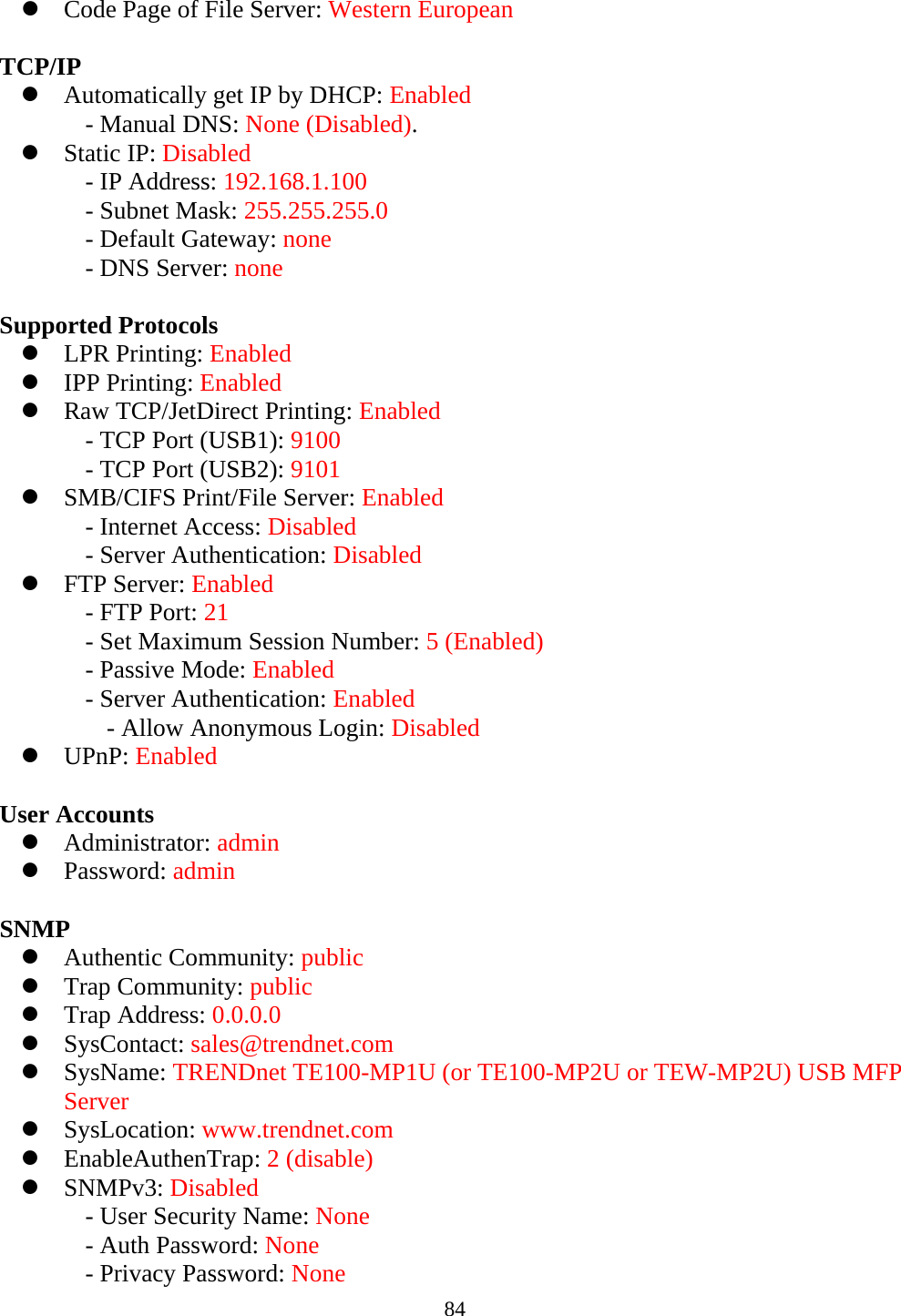
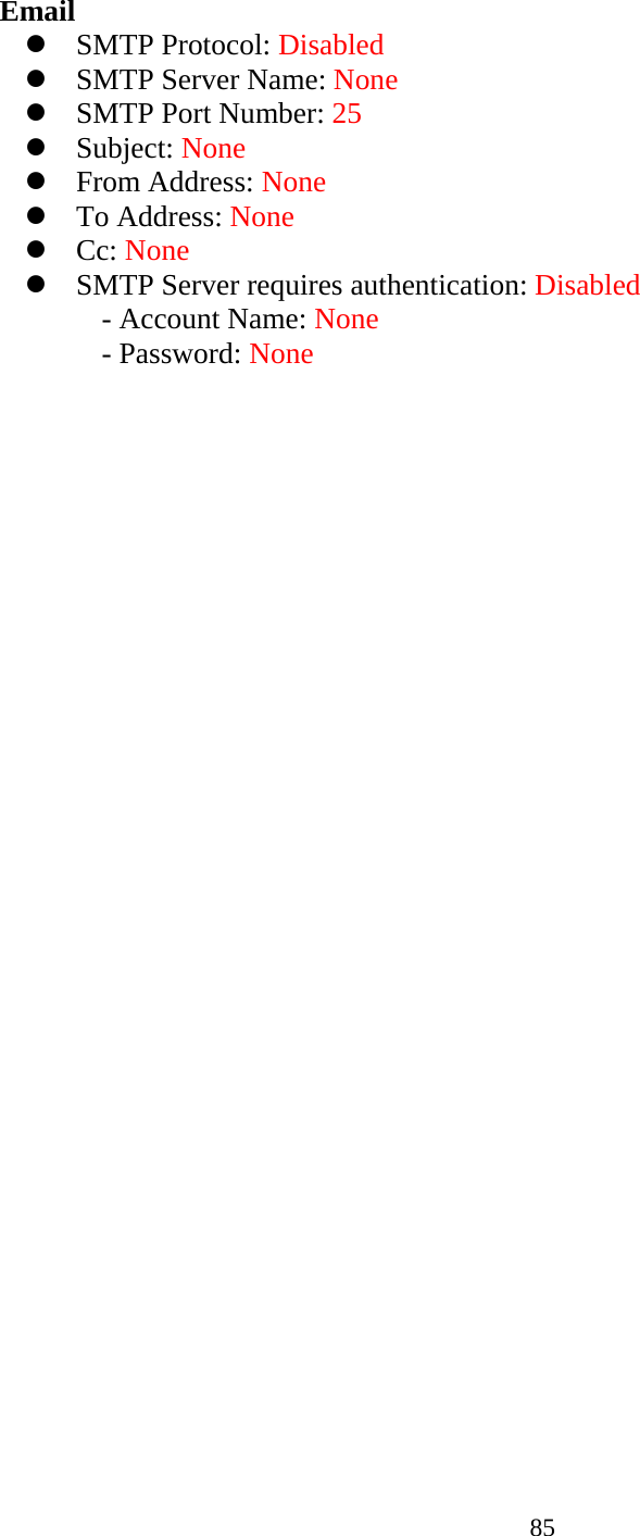
HTML
PDF
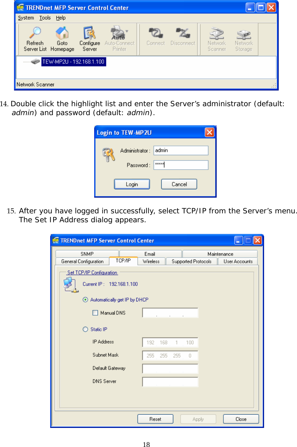
Info
Views
User Manual
Discussion / Help
Navigation