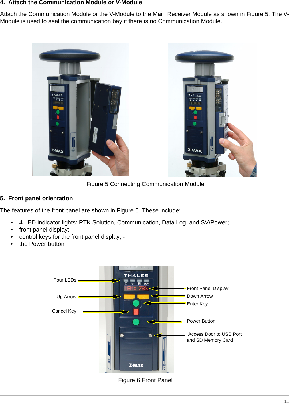
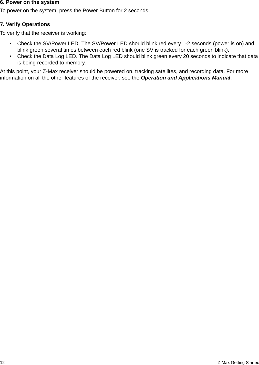
TRIMBLE EUROPE 110896 Communication Module for GPS Surveying Device User Manual Getting Started

TRIMBLE NANTES S.A.S. Communication Module for GPS Surveying Device Getting Started

Contents

Users Manual

Getting Started with Z-MaxZ-Max GPS Surveying SystemThales Navigation, Inc.471 El Camino RealSanta Clara, California  95050  USA                        Z.A.C. de La Fleuriaye,  B.P. 433                      44474 Carquefou Cedex                      France                                    www.thalesnavigation.com
  1IntroductionCongratulations! You have just acquired your new Z-Max™ GNSS Surveying System! GNSS (or Global Navigation Satellite System) has revolutionized control surveys, topographic data collection and construction surveying. Purchasing the right tools for a professional job is essential in today's competitive business environment and learning to put these tools to work quickly and efficiently will be the focus of the Z-Max user documentation.    If you're like us, then you're anxious to get started right away. You are not interested in reading a 300-page user manual or searching through five different documents trying to find out how to assemble and turn on your system.  You want the right information, at the right time as you take the steps required to master GNSS surveying. Getting Started with Z-Max is an easy-to-read booklet to help you identify and assemble the basic parts of the system. The additional documentation section of this guide provides references to other system documentation you will need as you become more familiar with the Z-Max System.    The Getting Started pamphlet will address the following questions: • What are all the pieces in the shipping case?• Did I receive everything I ordered?• How does everything fit together?• How can I quickly get started with my system?• What documentation contains what information?• Who do I contact if I need  help?The Getting Started pamphlet will not tell you how to survey with the system, or describe the technical features of the system.  The Getting Started pamphlet will give references to other user guides that will detail the technical features of the Z-Max and surveying applications. The Z-Max is a professional tool, and users are strongly advised to understand land surveying principles and procedures before using this system.
2Z-Max Getting StartedWhat is in the shipping case? You have opened your shipping case and you are looking at a collection of smaller containers that hold the system accessories.  Underneath the tray holding the smaller Z- Max parts, you will find a rugged case containing the Z-Max Main Module. The flexibility of the Z- Max system means each shipment may be different depending on your needs.  To verify your shipment,  compare each item in the case with the items listed in the Shipping Document. Important items will have part numbers on them and can be cross-referenced with the Shipping Document.   Z-Max GPS Receiver Module (P/N 800963)GPS Antenna Module (P/N 800961)Power Module and Charger Max-Run (P/N 800974) or Max-Lite (P/N 800975)This is the device that handles all the measuring, recording, and processing of satellite measurements. It also features a system control interface on the front panel.This is a highly sensitive antenna captures the faint signals from the GNSS satellites. It is required for the GPS Receiver Module to operate correctly.The Z-Max Battery Module and charger. The Battery Module provides power for the system. The charger is used to restore power in the battery.
  3Z-Max Communication Module (P/N 800964-0x)Z-Max V Module (P/N 800964-01)Interface CablesRover data link modules with UHF radios or cellular modem.For non-real-time systems, this device seals the communications bay from moisture. The V-Module looks similar to a Communications Module, so be sure to verify the part number.Cables for downloading data from the Z-Max receiver to an office computer for processing.USB Cable (P/N 110949)Serial Data Cable (P/N 700461)
4Z-Max Getting StartedTripod Mounting Tribrach adapter (P/N 101199)HI Measurement Tool (P/N 701083)HI Measurement Plate  (P/N 204456)
  5Typical Real-Time-Enabled Systems Will Include: Vortex UHF Antenna Module (P/N 800962-x0)Base Radio and AntennaThe rover UHF radio antenna.Thales U-Link Transmitter (P/N 80098x-xx)Base Radio, Data/power Cable, AntennaPacific Crest UHF Transmitter (P/N 110972-0x )Base Radio, Data/power Cable, Antenna
6Z-Max Getting StartedRTK Pole (P/N 110977)Mounting Bracket (P/N 204439)The fixed-height survey pole.Bracket used to mount the data collector to the survey pole.
  7Typical Backpack-Mounted Rover Systems Will Include:Z-Max Backpack (P/N 204437)Range Pole RF Adapter (P/N 800979)Max-RF Adapter (P/N 800978)Provides a comfortable way for a person to carry the Z-Max on their back.  Provides a cable interface on the survey pole. Used when the Z-Max is in Backpack Configuration. Provides a cable interface on the GPS Receiver Module. Used when the Z-Max is in Backpack Con-figuration.
8Z-Max Getting StartedGPS-RF Cable (P/N 730478)UHF-RF Cable (P/N 730473)The GPS-RF cable that connects the Range Pole RF Adapter to the Max-RF Adapter. The cables for the GPS RF and the UHF RF are identical except for color coding; the GPS RF cable is coded black. Cables are required when the Z-Max is in Backpack Configuration.The UHF-RF cable that connects the Range Pole RF Adapter to the Max-RF Adapter. The cables for the GPS- RF and the UHF-RF are identical except for color coding; the GPS-UHF cable is coded grey. Cables are required when the Z-Max is in Backpack Configuration.
  9Getting StartedLet's get your system operational. 1.  Charge the Power Module The Power Module will arrive partially charged, but the charge level may be from 1% to 90%. So, plug in your charger and connect the Power Module to the charger as shown in Figure 1. Charge the Power Module for at least  2-3 hours to make sure that your Power Module is charged enough to get you through this booklet.  Charging the Power Module overnight is recommended. If you don't completely charge your Power Module now, be sure to do so before going out into the field. 2.  Attach the Power Module to the GPS Receiver Module. Attach the Power Module to the GPS Receiver Module as shown in Figure 2.   Figure 1 Power Module and Charger Figure 2 Power Module and GPS Receiver Module
10 Z-Max Getting Started If you are using an external power source instead of the Power Module, plug the external power cable (attached to whatever power source you are using) into the rear panel of the Main receiver Module at the port marked 'POWER' as shown in Figure 3.  3.  Attach the GPS Antenna Module Attach the GPS Antenna Module to the GPS Receiver Module as shown in Figure 4. For the Z-Max to track satellites, the system should be outside and the GPS antenna should have a relatively open view to the sky.   Figure 3 Connecting External Power to Main Module Figure 4 Connecting GPS Antenna Module
 114.  Attach the Communication Module or V-Module Attach the Communication Module or the V-Module to the Main Receiver Module as shown in Figure 5. The V-Module is used to seal the communication bay if there is no Communication Module.  5.  Front panel orientation The features of the front panel are shown in Figure 6. These include: • 4 LED indicator lights: RTK Solution, Communication, Data Log, and SV/Power; • front panel display;• control keys for the front panel display; -• the Power button  Figure 5 Connecting Communication Module Figure 6 Front PanelFront Panel Display Down Arrow  Enter Key  Power Button  Access Door to USB Portand SD Memory CardFour LEDsUp ArrowCancel Key
12 Z-Max Getting Started6. Power on the system To power on the system, press the Power Button for 2 seconds. 7. Verify Operations To verify that the receiver is working: • Check the SV/Power LED. The SV/Power LED should blink red every 1-2 seconds (power is on) and blink green several times between each red blink (one SV is tracked for each green blink). • Check the Data Log LED. The Data Log LED should blink green every 20 seconds to indicate that data is being recorded to memory. At this point, your Z-Max receiver should be powered on, tracking satellites, and recording data. For more information on all the other features of the receiver, see the Operation and Applications Manual.
 13Additional Documentation Some additional documentation is provided in print and others are on CD-ROM. The exact documentation you received depends on what software and accessories you purchased. Z-Max Operation and Applications Manual This manual covers all aspects of the receiver as well as how to setup a static, kinematic, and an RTK survey. This manual also covers a number of  receiver functions, and reading it before performing GNSS surveys is strongly recommended. The manual comprises 3 sections: Operation and Reference section that contains: • a detailed description of each of the modules,• a description of the LEDs, the front panel display and external ports, • a more extensive Getting Started that includes monitoring receiver status and saving user parameters, • a detailed description of the front panel display menus, • operational topics such as data collection and downloading. System Guide to Post-Process Surveying section that contains:• a description of each of the modules used in a post-process survey, • detailed instructions on connecting the modules, • step-by-step guide to static and kinematic survey setup and execution, • a troubleshooting guide. System Guide to RTK Surveying section that contains:• a description of each of the modules used in an RTK survey, • detailed instructions on connecting the modules for an RTK survey, • step-by-step guide to RTK survey setup and execution, • a troubleshooting guide.Field Application Software Guide This manual covers the field application software that runs on the handheld computer/data collector. This manual covers the following: • a detailed description of the graphical interface; • a description of how to use the software to configure, execute, and monitor different kinds of surveys; • how to use the graphical and mapping capabilities in the software;  • how to use the additional surveying utilities such as COGO and Stakeout. • a brief description of the field computer hardware. Office Software Manual This manual covers all aspects of the PC software but your functionality will depend on software options that were purchased. This manual covers the following: • downloading data from the receiver or the handheld data collector;• post-processing raw data and performing quality assurance;• map making and data preparation and analysis; • creating background map projects to allow you to combine survey results with ESRI shape and raster files, • additional software utilities such as Mission Planning, WinComm, Geoids, Download, CE Download, RINEX converter, and DSNP-to-RINEX. Z-Max System Pocket Guide This pocket guide is a quick reference guide to using the Z-Max Surveying System. The guide provides a short description of the modules and their functionality including using LEDs, front panel display menus and setting up a receiver during a static, kinematic, or RTK survey. This manual is meant to be used as a quick reference reminder in the field and does not contain complete explanations for use and set up.
14 Z-Max Getting StartedAdditional Help If you have any problems with missing equipment, basic setup, or require further assistance, you can contact Technical Support by telephone, email, or Internet. If you need more information than is included in this brief Getting Started, then please spend some time with the enclosed documentation before contacting Technical Support. Thales Navigation Products Technical SupportNorth, Central, and South America (NCSA) plus International Monday thru Friday, 7:00 A.M. to 5:00 P.M. (PST, GMT -8 hours/PDT, GMT -7 hours) Tel: 800 229 2400, Option 1 (North America) Tel: 408 615 3980 or 408 615 3981 (International) Fax: 408 615 5200 Email: professionalsupport@thalesnavigation.com Europe, Middle East, and Africa (EMEA) plus International Monday thru Friday, 8:00 A.M. to 6:00 P.M. (GMT +1) Tel: 33 2 2809 39 34 Email: professionalsupportemea@thalesnavigation.comWhen contacting Technical Support, the following minimum information is required: Receiver serial number Software version number Software key serial number, if applicable Firmware version number A clear, concise description of the problem.  Also visit the Thales Navigation FTP site at ftp://ftp.thalesnavigation.com for updates to current firmware, software, product release notices, PDF versions of manuals, training materials, and FAQs. © 2003 Thales Navigation, Inc. All rights reserved. Z-Max is a trademark of Thales Navigation.
EnglishFrançaisAddendumReplacing the Thales U-Link Transmitter Power FuseThe Thales U-Link transmitter is protected by a 4-A fuse inserted in the data/power cable. This Y-shaped cable is used to connect the U-Link transmitter to the Z-Max receiver via a 7-pin connector, and to the power battery.Should you have to replace this fuse, please get a spare fuse, 4 A, fast acting, ATO type, and then do the following:• Unplug the battery end of the data/power cable• Open the fuse holder located along the data/power cable• Extract the damaged fuse• Insert the new fuse and then push the holder lid back into place• Connect the data/power cable back to the battery.Battery Charger / External Power SupplyThe Power Module contains rechargeable lithium-ion battery cells and “smart” charging circuitry. Recharging the Power Module is done using the AC/DC power supply, included with the System. This power supply can also be used to provide power directly to the Z-Max through an external connector. The charger is designed to work with a 110-240 VAC power source and delivers 12 V DC of input volt-age with at least 4-A current capability to the Power Module.Use of non-Thales power supplies for charging the Power Module is not recommended.FCC DeclarationZ-Max Receiver complies with the limits for a Class B digital device, pursuant to the Part 15 of the FCC rules when it is used in Portable Mode. See Note below related to Class B device.Class B digital devices NOTE: This equipment has been tested and found to comply with the limits for a Class B digital device, pursuant to Part 15 of the FCC Rules. These limits are designed to provide reasonable protection against harmful interference in a residential installation. This equipment generates, uses, and can radiate radio frequency energy and, if not installed and used in accordance with the instructions, may cause harmful interference to radio communi-cations. However, there is no guarantee that interference will not occur in a particular installation. If this equipment does cause harm-ful interference to radio or television reception, which can be deter-mined by turning the equipment off and on, the user is encouraged to try and correct the interference by one or more of the following measures:- Reorient or locate the receiving antenna. - Increase the separation between the equipment and receiver. - Connect the equipment into an outlet on a circuit different from that to which the receiver is connected. - Consult the dealer or an experienced radio/TV technician for help.When Z-Max is used with an external power supply or connected to an external device using the USB port, it complies with the limits for a Class A digital device, pursuant to the Part 15 of the FCC rules. See Note below related to Class A device.Class A digital devices NOTE: This equipment has been tested and found to comply with the limits for a Class A digital device, pursuant to Part 15 of the FCC Rules. These limits are designed to provide reasonable protection against harmful interference when the equip-ment is operated in a commercial environment. This equipment gen-erates, uses, and can radiate radio frequency energy and, if not installed and used in accordance with the instruction manual, may cause harmful interference to radio communications. Operation of this equipment in a residential area is likely to cause harmful interfer-ence in which case the user will be required to correct the interfer-ence at his own expense.Remark: Any changes or modifications not expressly approved by Thales Navigation, could void the right for user to operate the equip-ment.Remplacement du fusible d’alimentation de l’émetteur U-Link ThalesL’émetteur U-Link Thales est protégé par un fusible de 4 A inséré dans le câble alimentation/données. Ce câble en forme de Y est utilisé pour relier l’émetteur U-Link au récepteur Z-Max d’une part, via un connecteur 7 bro-ches, et à la batterie d’alimentation d’autre part.Au cas où vous auriez à remplacer le fusible, se procurer un fusible de rechange de 4 A rapide, type ATO, puis procéder comme suit :• Déconnecter le câble alimentation/données au niveau de la batterie• Ouvrir le support de fusible situé sur le câble alim/données• Extraire le fusible endommagé• Insérer le nouveau fusible puis refermer le couvercle du support• Re-connecter le câble alimentation/données à la batterie.Chargeur de batteries / Alimentation externeLe module Alimentation contient des batteries Li-ion rechargeables et un cir-cuit de chargement “intelligent”. Le rechargement du module Alimentation nécessite l’utilisation d’une alimentation secteur fournie avec le système. Cette alimentation peut aussi être utilisée pour alimenter directement le Z-Max via un connecteur externe. Le chargeur fonctionne à partir du secteur 110-240 V AC et fournit une tension continue de 12 V DC avec un courant de sortie d’au moins 4 A vers le module Alimentation.Il est déconseillé d’utiliser une alimentation autre que celle fournie par Thales pour charger le module Alimentation.Déclaration FCCLe récepteur Z-Max est conforme aux limites fixées pour un appareil numéri-que de classe B, conformément à la section 15 de la réglementation FCC lorsqu’il est utilisé en système portable. Voir la note ci-dessous concernant les appareils de classe B.NOTE concernant les appareils numériques de classe B : Ce type d’équipe-ment a été testé et s’est révélé conforme aux limites pour un appareil numé-rique de classe B, conformément à la section 15 de la réglementation FCC. Ces limites sont conçues pour fournir une protection convenable contre les perturbations dans une installation résidentielle. Ce type d’équipement génère, utilise, et peut émettre des ondes radio-électriques et, s’il n’est pas installé et utilisé selon les instructions fournies, peut perturber les communi-cations radio. Toutefois, il n’est pas exclu que des perturbations puissent se produire dans une installation donnée. Si ce type d’équipement perturbe la réception de la radio ou de la télévision, ce qui peut être constaté en coupant puis en rallumant l’équipement, l’utilisateur est incité à mettre fin aux pertur-bations en prenant l’une des mesures suivantes :- Réorienter ou repositionner l’antenne de réception.- Augmenter la distance entre l’équipement et le récepteur.- Connecter l’équipement sur une prise reliée à un circuit autre que celui sur lequel le récepteur est branché.- Demander de l’aide auprès du revendeur ou d’un technicien radio/TV expé-rimenté.Lorsque le Z-Max est utilisé avec une alimentation externe ou s’il est con-necté à un système externe via le port USB, il est alors conforme aux limites fixées pour un appareil de classe A, conformément à la section 15 de la réglementation FCC. Voir Note ci-dessous concernant les appareils de classe ANOTE concernant les appareils de classe A : Ce type d’équipement a été testé et s’est révélé conforme aux limites pour un appareil numérique de classe A, conformément à la section 15 de la réglementation FCC. Ces limi-tes sont conçues pour fournir une protection raisonnable contre les perturba-tions lorsque ce type d’équipement est utilisé dans un environnement commercial. Ce type d’ équipement génère, utilise, et peut émettre des ondes radio-électriques et, s’il n’est pas installé et utilisé selon les instruc-tions du manuel, peut perturber les communications radio. L’utilisation de ce type d’équipement dans une zone résidentielle a de fortes chances de pro-voquer des perturbations, auquel cas l’utilisateur devra par ses propres moyens se libérer de ses perturbations.Remarque : Tout changement ou modification non approuvé explicitement par Thales Navigation peut retirer à l’utilisateur le droit d’utiliser cet équipe-ment.
EspañolDeutschCambiar el fusible de protección del transmisor  U-Link de ThalesEl transmisor U-Link de Thales está protegido mediante un fusible de 4 A introducido en el cable de datos/alimentación. Este cable, en forma de Y, se usa para conectar el transmisor U-Link al receptor  Z-Max, por medio de un conector de 7 patillas, y a la batería de  alimentación.En caso de tener que cambiar este fusible, utilice un fusible de repuesto, de 4 A, rápido, de tipo ATO, y haga lo siguiente:• Desconecte el extremo del cable de datos/alimentación  correspondiente a la batería,• Abra el portafusibles, situado a lo largo del cable de datos/alimenta-ción,• Extraiga el fusible dañado,• Introduzca el nuevo fusible y vuelva a colocar la tapa del  portafusibles en su sitio,• Vuelva a conectar el cable de datos/alimentación a la batería.Cargador de batería / Suministro de energía externaEl módulo de alimentación contiene baterías de ión litio recargables y un cir-cuito de recarga "inteligente". La recarga del módulo de alimentación se lleva a cabo empleando el alimentador eléctrico CA/CC incluido en el sistema. Este alimentador puede utilizarse también para suministrar energía directa-mente al Z-Max por medio de un conector externo. El  cargador está diseñado para funcionar con un suministro eléctrico de 110-240 VCA, y proporciona 12 VCC de tensión de entrada, con una intensidad de al menos 4 A, al módulo de alimentación.Se recomienda no utilizar alimentadores eléctricos que no sean de Thales para cargar el módulo de alimentación.Declaración FCCEl receptor Z-Max se ajusta a los límites establecidos para los dispositivos digi-tales de Clase B, de acuerdo con la Sección 15 de las normas de la FCC, cuando se utiliza en modo portátil. Véase la nota a continuación con relación a los dispositivos de Clase B.Dispositivos digitales de Clase B NOTA: Se ha comprobado que este equipo se ajusta a los límites establecidos para los dispositivos digitales de Clase B, de acuerdo con la Sección 15 de las normas de la FCC. Dichos límites han sido diseñados para proporcionar una protección razonable  contra interferencias perjudiciales en una instalación residencial. Este equipo genera, utiliza y puede radiar energía a frecuencia de radio y, si no se instala y se utiliza de acuerdo con las instrucciones, puede provocar interferencias perju-diciales para las comunicaciones de radio. No obstante, no hay ninguna garantía de que no se producirán interferencias en una instalación concreta. En caso de que el equipo cause interferencias  perjudiciales a la recepción de radio o televisión, lo cual puede determinarse apagando y encendiendo el equipo, se recomienda al usuario que intente corre-gir las interferencias mediante la adopción de una o varias de las medidas siguientes:- Cambiar la orientación o la ubicación de la antena receptora. - Aumentar la separación entre el equipo y el receptor. - Conectar el equipo a un enchufe perteneciente a un circuito  distinto de aquél al que está conectado el receptor. - Solicitar ayuda al distribuidor o a un técnico especializado en radio/TV.Cuando Z-Max se utiliza con suministro energía externa o se conecta a un dis-positivo externo mediante el puerto USB, se ajusta a los límites  establecidos para dispositivos digitales de Clase A, de acuerdo con la  Sección 15 de las normas de la FCC. Véase la nota a continuación con relación a los dispositivos de Clase A.Dispositivos digitales de Clase A NOTA: Se ha comprobado que este equipo se ajusta a los límites establecidos para los dispositivos digitales de Clase A, de acuerdo con la Sección 15 de las normas de la FCC. Dichos límites han sido diseñados para proporcionar una protección razonable contra interferencias per-judiciales cuando el equipo se utiliza en un entorno comercial. Este equipo genera, utiliza y puede radiar energía a frecuencia de radio y, si no se instala y se utiliza de acuerdo con el manual de instrucciones, puede provocar interferen-cias perjudiciales para las comunicaciones de radio. La utilización de este equipo en una zona residencial puede provocar interferencias perjudiciales, en cuyo caso el usuario deberá corregir dichas interferencias a su propio cargo.Comentario : Algún cambio o modificación del aparato no aprobado explícita-mente por Thales Navigation podría impedir el usuario utilizar su equipo.Austausch der Sicherung des Thales U-Link-SendersIm Daten-/Stromkabel des Thales U-Link-Senders befindet sich eine Sicherung mit 4 Ampere. Dieses Y-Kabel verbindet den U-Link-Sender mit dem Z-Max (über den 7-Stift-Anschluss) und mit einer Batterie als  Spannungsquelle.Wenn Sie die Sicherung ersetzen müssen, verwenden Sie eine flinke  4 A-ATO-Sicherung und gehen Sie folgendermaßen vor:• Lösen Sie das Daten-/Stromkabel von der Batterie.• Öffnen Sie den Sicherungshalter im Kabellauf.• Entnehmen Sie die beschädigte Sicherung.• Setzen Sie die neue Sicherung ein und verschließen Sie den  Sicherungshalter.• Verbinden Sie das Daten-/Stromkabel wieder mit der Batterie.Batterieladegerät / Externe SpannungsversorgungDas Stromversorgungsmodul enthält aufladbare Lithium-Ion-Zellen und eine intelligente Ladeelektronik. Das Stromversorgungsmodul wird mit dem im Lieferumfang enthaltenen Netzteil aufgeladen. Dieses Netzteil kann auch verwendet werden, um den Z-Max direkt über einen externen Anschluss mit Strom zu versorgen. Das Ladegerät arbeitet im Bereich von 110 bis 240 Volt Wechselstrom und stellt 12 Volt Gleichstrom Eingangs-spannung mit mindestens 4 Ampere Belastbarkeit für das Stromversor-gungsmodul zur Verfügung.Von der Verwendung anderer Netzteile, als dem von Thales geliefer-ten des Stromversorgungsmoduls, wird abgeraten.FCC-ErklärungDer Z-Max-Empfänger entspricht den Grenzwerten digitaler Geräte der Klasse B, entsprechend Teil 15 der FCC-Richtlinien bei der Verwendung im portablen Modus.HINWEIS für digitale Geräte der Klasse B: Diese Ausrüstung wurde auf  Einhaltung der Grenzwerte für digitale Geräte der Klasse B gemäß Teil 15 der FCC-Richtlinien getestet. Diese Grenzwerte dienen dem Schutz gegen schädliche Strahlung in Wohnbereichen. Das Gerät generiert und benutzt Radiofrequenz-Energie und strahlt diese auch aus. Sofern es nicht in  Übereinstimmung mit der Anleitung installiert und betrieben wird, kann es  Störungen in der Radiokommunikation auslösen. Es kann jedoch nicht garantiert werden, dass unter bestimmten Voraussetzungen keine Störun-gen auftreten. Falls diese Ausrüstung den Empfang von Radio- oder  Fernsehprogrammen stört (Sie können dies durch Aus- und Einschalten der Ausrüstung feststellen), versuchen Sie, die Störung anhand folgender Maßnahmen zu beheben:- Neuausrichtung oder -positionierung der Empfangsantenne - Erhöhen des Abstandes zwischen Ausrüstung und Empfänger - Anschließen der Ausrüstung an einen anderen Stromkreis als den Empfän-ger - Wenden Sie sich an Ihren Händler oder einen erfahrenen Funk- oder Fernsehtechniker, wenn Sie Hilfe benötigen.Wenn der Z-Max mit einer externen Spannungsversorgung benutzt wird oder über den USB-Anschluss mit einem externen Gerät verbunden ist, entspricht er den Grenzwerten für digitale Geräte der Klasse A  entsprechend Teil 15 der FCC-Richtlinien.HINWEIS für digitale Geräte der Klasse A: Diese Ausrüstung wurde auf  Einhaltung der Grenzwerte für digitale Geräte der Klasse A gemäß Teil 15 der FCC-Richtlinien getestet. Diese Grenzwerte dienen dem Schutz gegen schädliche Strahlung beim Betrieb der Ausrüstung in gewerblichen  Umgebungen. Das Gerät generiert und benutzt RadiofrequenzEnergie und strahlt diese auch aus. Sofern es nicht in Übereinstimmung mit der  Betriebsanleitung installiert und betrieben wird, kann es Störungen in der Radiokommunikation auslösen. Der Betrieb der Ausrüstung in  Wohnbereichen führt wahrscheinlich zu schädlichen Störungen, so dass der Anwender die Störung auf eigene Kosten beheben muss.Bemerkung: Alle Änderungen oder Modifikationen, die nicht von Thales Navigation aussdrücklich genehmigt werden, können die Nutzerrechte für die Operation der Ausstattung beeintrachtigen.
DECLARATION OF CONFORMITYWe Thales Navigation, Inc. 471 El Camino RealSanta Clara, CA 95050 USATel: +1 408 615 5100declare under our sole responsibility that the productReference Number 800964-x Complies with Part 15 of the FCC Rules. Operation is subject to the following two condi-tions: (1) This device may not cause harmful interference, and (2) this device must accept any interference received, including interference that may cause undesired operation.

Navigation menu