TTI Tech GMRS-1200 2-WAY PORTABLE HANHELD RADIO User Manual CRN 21965 Revised
TTI Tech Co., Ltd. 2-WAY PORTABLE HANHELD RADIO CRN 21965 Revised
TTI Tech >
Contents
- 1. User Manual
- 2. Revised user manual to include FCC license info and RF exposure info
- 3. CRN 21965 Revised User Manual
CRN 21965 Revised User Manual
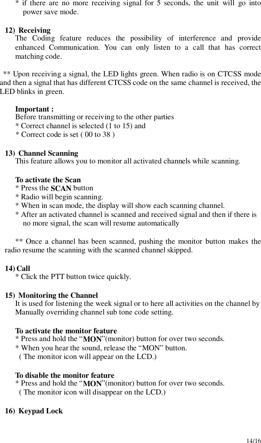
![11/163-3. SETTING AND OPERATIONIn order to communicate with other GMRS/FRS units, both you and the receiving party must be on the same channel. GMRS-1200 has 15channels indicated by the large digits on the LCD display panel. Before trying to transmit on the selected channel, you should press the Monitor Button to check the activity on that channel. If someone is already on the selected channel, you should try another channel that is clear1) On/Off & Volume control SwitchRadio ON : Press the power button at least for 2 seconds.You will hearconfirming melody to indicated the unit is on. Radio OFF : Press the power button at least for 2 seconds.Volume setting : Press up[″]or down[…] button to adjust a level that iscomfortable for you while monitor is active.2) Setting the Channel and Tone Code(CTCSS)GMRS-1200 has 15 main channels and 38 sub-channels.* 14 Frequency channels* 38 CTCSS Code ( indicated by CTC icon on the LCD )To select the channel* Turn the radio on.* Press MODE button once, [XX] digit will blink on the LCD. XX is achannel.* Press up[″]or down[…] button to choose the channel.* Press the PTT button or MODE button to confirm.To set the tone codes(CTCSS)* Press MODE button once more, [XX 00 up to 38] will appear and CTC iconand tone code digit will blink on the LCD. “00” means no CTCSS code.* Press up[″]or down[…] button to choose the desired sub-channel to use.* Press the PTT button or MODE button to confirm.NOTE : To communicate with other GMRS/FRS units, they mustbe switched to the same channel and CTCSS sub-code. Tocommunicate with other GMRS/FRS units that do not have sub-codes,switch your unit to the same channel with the sub-code set to OFF.3) VOX (Voice Operated Switching)This option enables you to have hands-free conversation. You do not have tooperate the PTT button each time when you want to transmit.You can also choose the VOX sensitivity so suit your environment ofoperation.](https://usermanual.wiki/TTI-Tech/GMRS-1200.CRN-21965-Revised-User-Manual/User-Guide-225758-Page-11.png)
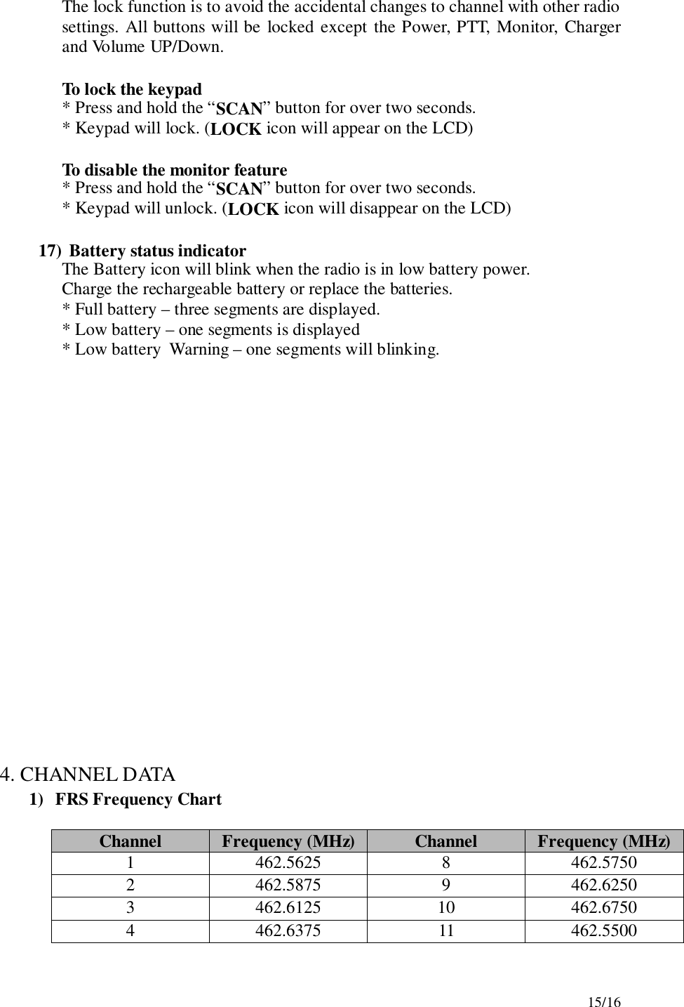
![12/16( Ex : noisy road, motor bike, factory etc. )To Set the VOX mode* Press the MODE button until the [Uo oF Or XX] appears. XX is a vox level* VOX icon will be appeared on the LCD.To Set the VOX level* Press the up[″]or down[…] button to set the VOX level from 1 to 5.“oF” is disable the VOX function.“01” is least sensitive.“05” is most sensitive.* Press the PTT button or MODE button to confirm.4) Setting the DW (dual watch)To set the DW mode* Press the MODE button until the [ oF of 01 up to 15] and DW icon blink onthe LCD.* DW icon will appear on the LCD.To set the dual watch(DW) channel* Press the up[″]or down[…] button to choose the channel.“oF” means no DW mode.“01 up to 15” means the channel that is dual-watched.* Press the PTT button or MODE button to confirm.5) Roger toneThis feature will give the tone signal to other parties when transmitting finished(when PTT button is released.)To activate or disable the Roger tone* Press the Mode button until [rb on or oF] and the roger icon blink on theLCD.* Press the up[″]or down[…] button.* Press the PTT button or MODE button to confirm.6) Beep toneTo set the beep tone* Press the Mode button until [bP on or oF] and the BELL icon blink on theLCD.* Press the up[″]or down[…] button.* Press the PTT button or MODE button to confirm.7) Setting Out of Range](https://usermanual.wiki/TTI-Tech/GMRS-1200.CRN-21965-Revised-User-Manual/User-Guide-225758-Page-12.png)
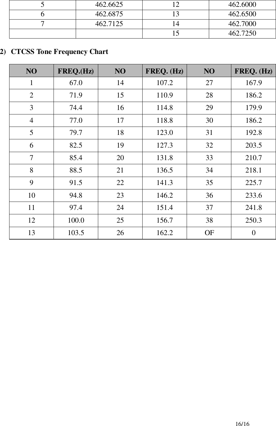
![13/16To set the Out of Range* Press the Mode button until [ir on or oF] and the Out of Range icon blinkon the LCD.* Press the up[″]or down[…] button.* Press the PTT button or MODE button to confirm.8) Setting ID codeTo set the Caller ID! Press the MODE button until the ID Icon and small segment display blinks.! Then press the Up or Down button to select the desired ID number from 01to 10. “oF” means no ID mode.! Press the PTT button or Mode button momentarily to confirm the IDnumber.** When a signal is received from the radio where the one Caller ID isselected, the radio that is receiving the signal displays the Caller ID number ofthe transmitting radio.9) Weather alert settingTo set the Weather alert receiving mode* Press the MODE button until the [AL on or oF] blinks* Press the up[″]button or down […]button to set the alert function.* While the alert is ON, weather icon will blink both in FRS and weathermode.* Weather icon will stop the blinking on the LCD when the alert is OFF.** While the unit is GMRS/FRS mode, if the alert signal is received, the unitwill set to Weather Radio mode automatically and warning beep tone willgenerate.** While the unit is in Weather mode, if the alert signal is received, the unitwill generate the warning beep tone.10) Call Ringer Selection ModeThis feature Provides 3 user selectable call ringer signal.To set your favorite call ringer signal.* Press the MODE button until the [C 01 or up to 03] appears on the LCD.* Press the up[″]or down[…] button to select the call melody type.* Press the PTT button to confirm.* To activate the call, click the “PTT” button twice quickly.11) Transmitting* Press and hold the PTT button (The LED light red during transmission.)* Speak slowly and clearly* To Stop the transmission, release the PTT button.](https://usermanual.wiki/TTI-Tech/GMRS-1200.CRN-21965-Revised-User-Manual/User-Guide-225758-Page-13.png)