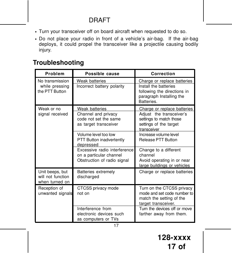
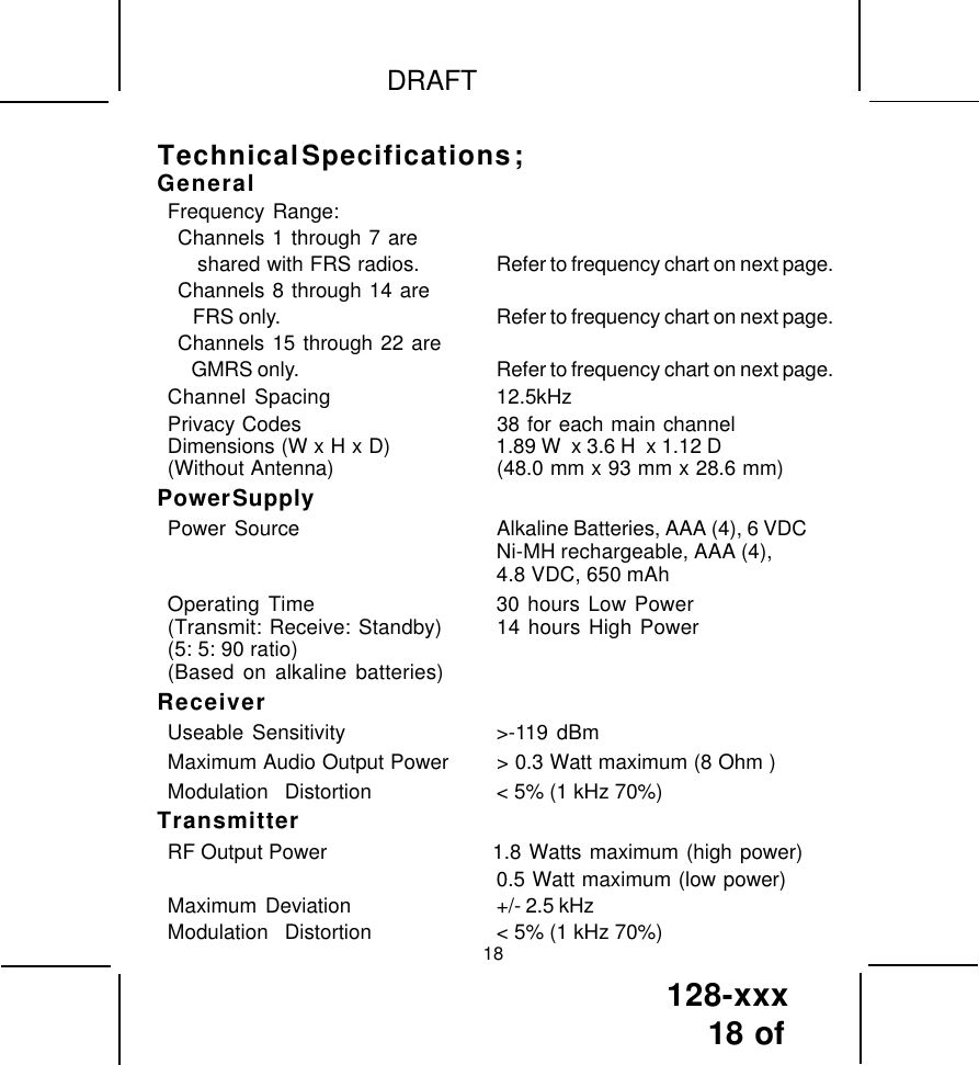
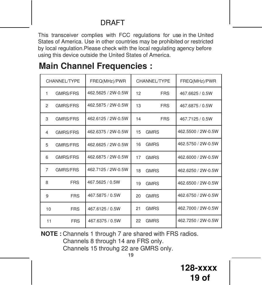
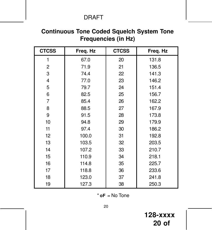
TTI Tech GMRS122 FRS/ GMRS Combination User Manual users manual

TTI Tech Co., Ltd. FRS/ GMRS Combination users manual

users manual

128-XXXX  1 of General Mobile Radio Service (GMRS)Model : GMRS122-2CHDraft :Owner's Manual1-800-290-6650DRAFT1-15-03(by TTI).
128-XXXX 2 of NEVER ATTEMPT TO CHARGE ALKALINE OR DRY CELL BATTER-IES, AS BATTERIES MAY BURST CAUSING PERSONAL INJURYAND DAMAGE TO THE PRODUCT.  WHEN RECHARGING NICKELMETAL HYDRIDE (Ni-MH) BATTERIES WITH THE AUDIOVOXCHARGER, USE ONLY AUDIOVOX APPROVED RECHARGE-ABLE BATTERIES. USE OF THE AUDIOVOX CHARGER WITHOTHER BRANDS OF BATTERIES IS NOT RECOMMENDED, ASBATTERY CHARGING TIMES WILL VARY WITHDIFFERENT BRANDS. REFER TO THE  MANUFACTURER’SINSTRUCTIONS FOR CHARGING OTHER BRANDS OF BATTERIES.AVOID PLACING THE GMRS-3000PK RADIO TRANSCEIVERFOR PROLONGED PERIODS OF TIME IN DIRECT SUNLIGHTOR TEMPERATURES BELOW -4° F (-20° C) OR ABOVE 140 ° F(60° C).KEEP THE ANTENNA  AT 1 INCH (2.5 cm) AWAY FROM YOURHEAD AND BODY.  DO NOT USE YOUR GMRS122-2CH RADIOTRANSCEIVER WITH A DAMAGED ANTENNA.PLACE THE RUBBER COVER ON JACKS WHEN NOT IN USE.GMRS LICENSE:USE OF THIS RADIO WITHIN THE UNITED STATES REQUIRES ANFCC GMRS LICENSE.  AN INDIVIDUAL18 YEARS OF AGE OROLDER, WHO IS NOT A REPRESENTATAIVE OF A FOREIGNGOVERNMENT, IS ELIGIBLE TO APPLY FOR A GMRS SYSTEMLICENSE.  YOU WILL NEED TWO FORMS FROM THE FCC; FCCFORM 159 AND FCC FORM 605 MAIN FORM AND SCHEDULE F.YOU CAN FIND THE FORMS ONLINE AT: HTTP://WWW.FCC.GOV/FORMPAGE.HTML, OR CALL 1-800-418-3676.CAUTIONS2
128-XXXX3 of DRAFT31. Battery Cover2. Monitor/Function ConfirmationButton3. Detachable Carry Clip4. Push-To-Talk (PTT) and Func-tion Confirmation Button5. Antenna6. External Speaker(SP.)/Micro-phone (MIC) Jacks7. Built-in Speaker8. Liquid Crystal Display (LCD)9. Built-in MicrophoneModel GMRS122-2CH   (FCC License Required)10. Up Channel/Volume Button11. Down Channel/VolumeButton12. MODE Button13. Power (PWR) On/Off & SCAN Button  14. Battery Charging Contacts1435412913118101273(REF)1(REF)6
128-xxxx4 of DRAFTModel GMRS 122-2CH DISPLAY41. RogerBeep Tone On/Off Indicator: 2.3. Monitor Indicator:  Icon appears when the Monitor (M) button ispressed and the channel monitor function is activated.Icon appearsalso when a signal is being received.  The icon also represents transmit signal power during   4. Large Segment Display:  Indicates the channel number in use.5. Scan Indicator:  This function allows the user to scan a channel and/or atone code every .5 second to search for a valid signal.  6. Battery Level Indicator:  Icon indicates when the battery is low level.7.  Hi/LO Indicators:  Appropriate icon appears when the transmit poweris set to desired output power.786543219Roger Beep tone is on, and disappears when tone is not in use.Transmit Indicator:transmission.This icon appears when the8. Small Segment Display:  Displays the CTCSS tone option in thechannel from (00-38). 9. Voice Activated Transmission (VOX) Indicator:  This function allowshands free conversation. The icon appears when the VOX mode isactivated.
128-xxxx5 of DRAFT5Equipment and Accessories Supplied1. Radio (2) GMRS122-2CH2. Owner’s Manual (1) 128-xxxx3. Batteries (8) Rechargeable NiMH4. Dual Desk-Top Charger DTC122-2CH5. AC Wall Adapter                                UD-1201BPowering the transceiver:Your GMRS122-2CH radio transceiver operates on four AAA batteries.Alkaline batteries will provide slightly better performance than rechargeablebatteries.  Only the supplied Audiovox-approved rechargeable batteriescan be recharged in the radio transceiver using the suppiled desk-topcharger and associated wall adapter. This will ensure optimumperformance for the GMRS122-2CH. Battery charging time is typically10-12 hours. Use of the Audiovox charger with other brands of batteries isnot recommended as battery charging times will vary. Refer to themanufacturer’s instructions for charging other brands of batteries.BatteriesThere are three methods of powering the GMRS122-2CH:1. Alkaline Batteries.WARNING:  Do not attempt to recharge Alkaline batteries.2. Audiovox Rechargeable Ni-MH Batteries - (Rechargeable Ni-MHbatteries, Wall Adapter and Charging Stand included).
128-xxxx6 of DRAFT62. Slide the coverdown and then liftcover at bottom toopen.Removecover.3. Insert four AAA batteries(positive (+) end towardthe top begining at  leftside and alternatingpositive terminals asshown).1. Using thumb,press down onbattery cover atarrow and slidecover down toopen.Use only Audiovox-approved rechargeable batteries and chargerwhen charging batteries internal to the unit.NOTE: To extend battery life, avoid overcharging the batteries.3. Various Brands of Rechargeable Batteries - Use of  theAudiovox charger with other brands of rechargeable batteries is notrecommended, as battery charging times will vary with differentbrands of batteries. Refer to the manufacturer’s instructions forcharging other brands of batteries.Installing the batteries:Battery installation  is made more convenient when the carry clip is removed.To do this, release the spring clip securing the belt clip to radio and slidethe belt clip upward and away from the radio body.   Next, press down withthe thumb at the embossed arrow, slide the battery cover down and lift offthe battery cover. Insert four AAA batteries (alternate positive ends (+) towardthe top of the transceiver, starting left-to-right.RELEASEBUTTON CLIPBATTERYCOVERBELTCLIPCOVERARROWPOSITIVETERMINALSCLIP+     ++     +
128-xxxx7 of DRAFT7The following guidelines will improve performance and provide longeroperating times for the GMRS122-2CH:1. Do not mix old and new batteries.2. The use of alkaline-type batteries is recommended to provide thelongest operating time.3. Do not mix alkaline, standard (carbon-zinc) or rechargeablebatteries.4. If the unit is not to be used for an extended period of time, remove thebatteries.  Old or leaking batteries can cause damage to the unit andwill void the warranty.AC WALLADAPTER/CHARGINGTRANSFORMERMODEL: UD-1201BINPUT     :  110VACOUTPUT :   DC12VDESKTOP CHARGING STANDPART NUMBER DTC122-2CHCHARGING STANDPWR JACKADAPTERPOWERPLUGGMRS RADIOCHARGINGCOMPARTMENTS (2)PWRCHARGINGCOMPARTMENTLEDs:RED---CHARGING+-
128-xxxx8 of 8NOTE:To differentiate between operating modes, look for HI or LO indicationRefer to the appropriate section of this manual for detailed operatinginstructions for each mode.When in standby mode,the transmit/receive indicator will flash once every 5 seconds as the unit is in thepower-save mode.GMRS122-2CH OPERATIONAL MODESGMRS/FRS BANDROGERBEEPPOWERSELECTCTCSSSELECTCHANNELSELECTbelow the battery power level indicator when in GMRS mode.
128-xxxx9 of 9Controls:Power On/Off (13) ButtonPress and hold the power on/off button (PWR  ) for at least 2 seconds. You willhear a confirming melody to indicate the unit is on.  To turn the unit off, pressand hold the button for at least 2 seconds.Adjusting the VolumeWith the unit powered on, press the Up Channel/Volume button (   ) toincrease volume and the Down Channel/Volume button (   ) to decreasevolume.  The display will indicate the current volume level by the smallnumber in the icon (UL 0 - 7     ).Monitor/Display Backlight Button (2)This button is used to to check activity on the current frequency beforetransmitting.  Check activity by pressing the Monitor (M) Button longerthan 2 seconds;the BUSY   icon will apppear on the display and you willhear static if  frequency is clear.  Do not transmit if you hear conversation.Hold down the Monitor Button again longer than 2 seconds and the icon will disapppear from the display.The monitor function will temporarily bypass the squelch setting and playall signals on a given channel.  This feature is useful when communicatingwith other parties at extreme range.By pressing the monitor button momentarily, the LCD backlight is turnedon; the LCD backlight will turn off automatically in about 5 seconds, orwhen the monitor button is pressed momentarily once again.Push To Talk (PTT) Button (4)Pressing and holding this button will allow you to speak to any transceiverthat is set to the same channel and privacy code setting as yours.  Hold thetransceiver approximately 1 to 2 inches from your face as you speak intothe built in microphone (9).  After you have finished speaking, release thePTT Button to allow  reception of incoming signals.  It is not possible to
128-xxxx10 of 10transmit and receive at the same time.   While the PTT Button ispressed and the TX indicator on the LCD will be display. Releasing the button allows the unit to revert to standby mode.  Whenreceiving an incoming signal,The PTT Button can also be used as a two-way call ringer. Pressing thebutton twice quickly will call another party on the same channel.  The Transmiticon on the LCD will displayed for 3 seconds and then go out.Up Channel/Volume Button (10)In the standby mode, pressing this button will increment the listeningvolume. When in function edit mode this button will be used to adjust theunit's settings.Down Channel/Volume Button (11)In the standby mode, pressing this button will decrement the listeningvolume. When in function edit mode this button will be used to adjust theunit's settings.MODE Button (12)This button is used to select various feature settings in the GMRS and FRS.
128-xxxx11 of 11External Speaker (SPK) / Microphone (MIC) Jacks (6)This set of jacks accepts an Audiovox headset/microphone connector.Scan  Button (13)Press this Button momentarily to enable or disable the scan mode.  Operating Modes and FeaturesGRMS/FRS Operation- From GMRS/FRS standby mode, press and hold the (PWR) button for 2 seconds to turn on power.- Press the MODE button so the Channel number flashes.- Select the desired channel with the Up (10) and Down (11) Buttons.When receiving a call, the BUSY icon on the LCD appears to indicateincoming received signal - Press and hold the PTT button (4) to transmit, then speak into themicrophone clearly and slowly. - Release PTT Button (4) to receive.- Communication can only be accomplished when the channel andCTCSS tone frequency of at least two parties are the same.
128-xxxx12 of 12Channel SelectionIn order to communicate with other GMRS/FRS units, both transmittingand receiving party must be on the same frequency.The GMRS122-2CH has 22 channels (frequencies) (1-22) indicated bythe large digits on the LCD display panel.   Channels 1 through 7 arethe shared GMRS/FRS channels. Channels 8-14 are FRS only chan-nels,while channels 15-22 are assigned GMRS only channels.If a FRSonly channel(8-14) has been selected, the HI or LO icon will not bedisplayed on the LCD panel; otherwise,for channels 1-7(GMRS/FRS)and 15-22(GMRS only), the HI or LO icon will be displayed.Communication with Audiovox GMRS/FRS and compatible units is possibleon these 22 channels. Before transmitting on the selected channel, pressthe Monitor (M) Button(2) to check the activity on that channel. If thereis activity on the selected channel,change to another channel that is clear.To change the channel,- From GMRS/FRS standby mode,  press the MODE button (12)until the channel number flashes.- Press the Up Button (10) briefly to move to the next higher mainchannel number.- Press the Down Button (11) briefly to move to the next lower mainchannel number.CTCSS Mode (Sub-Channel) SelectionCoded Tone Controlled Squelch System (CTCSS) with 38 Sub-Frequencies.This feature allows you to utilize the coded squelch tones (01–38) within amain channel. This enables you to communicate with another party on thesame main channel using the same subcode.  (This filters out unwantedtransmissions without the same coded squelch tone).  There are 38 CTCSSSub-channels for each main channel.  A different subcode may beselected for each of the 22 channels.
128-xxxx13 of 13- Press the Up or Down button to select  the desired sub-channelfor use (1-38).- Press the PTT or Power On/Off button to confirm selection.The CTCSS mode can be turned off by selecting the oF icon as the setting.NOTE: To communicate with other GMRS/FRS units, they must be switchedto the same channel and CTCSS subcode. To communicate withother GMRS/FRS units that do not have subcodes, switch your unitto the same channel with the subcode set  to oF    .The CTCSS subcodes do not prevent others from hearing yourtransmission.  This will only allow you to ignore all traffic on agiven channel not using the same subcode.VOX Selection ModeThis option enables you to have hands-free conversation. Your voice ornearby sound is detected and the radio transmits without the need topress the PTT button.To set radio for VOX operation,- From GMRS/FRS standby mode,  press and hold the MODE button  until  VOXthe       icon display on the LCD.VOX can be turned off by pressing the MODE button for 3 seconds.- From GMRS/FRS standby mode, press the MODE twice;   a flashing oF or sub-channel number is displayed. To change the CTCSS Sub-channel,
128-xxxx14 of 14Channel Scan  OperationThis feature allows you to monitor all channels automatically for validsignals.  While scanning, you can transmit and receive. When a signal isreceived, the scan is interrupted and will return to scan mode 5 secondsafter reception is terminated.NOTE:While the scan function is active,the MODE button will be inoperative.Thescan mode will reduce the overall battery life due to the battery savefunction is overridden.To enable the channel scan mode,- From GMRS/FRS standby mode,momentarily press the power Button;(SCAN) will appear on the LCD display.- The radio will display each channel (1-22) in order as the scan modeoperates to find an active main channel.- When unit doesn't find any signals and you want to transmit, pressthe PTT switch to return to home channel operation.  The transceiverwill automatically resume scanning approximately 5 seconds afterthe communication is completed.- If there is no activity and you want to leave the scan mode, press thepower button momentarily and the unit will return to normal operation;(SCAN) icon will disappear from the LCD display.Key ToneThis feature allows the transceiver to sound a confirmation tone wheneverthe following keys are pressed: Monitor (M) Button,Up/Down Button, MODEButton, SCAN Button.The key tone is always on,not available to OFF.
128-xxxx15 of 15Transmit Power Selection ModeThis feature permits selection of the transmitting power level to highor low.  Using low power the unit will have a lower transmit range butbattery life will be increased. To access the transmitter power selection function:- From GMRS standby mode, press the Function Button until the Po iconappears with a flashing HI or  Lo indication on the display.- Press the Up or Down button to toggle between the High and Low  se-lections.- Press the PTT or Power On/Off button to confirm selection.The display will indicate the current setting in standby mode.Roger Beep ToneThe Roger Beep is a tone which is automatically transmitted whenever thePTT button is released.  This tone alerts the receiving party that the trans-mission has been terminated intentionally.To enable and disable the Roger Beep tone:- From GMRS/FRS standby mode, press the Function Button  until rbappears on the display with the flashing Roger Beep icon (   ) andOn or oF.- Press the Up or Down Button to select the tone on or off as desired.- When enabled, the tone icon  (   ) appears steady on the display.- Press the PTT or Power On/Off button to confirm selection.Battery AlertWhen the battery icon (      ) blinks on the LCD panel, recharge unit or install fresh batteries.
128-xxxx16 of DRAFTNOTES FOR GOOD COMMUNICATION1 . The GMRS122-2CH 22 channels are shared on a ‘take turns’ basis.This means other groups may be talking on any of the channels.A common code of ethics/courtesy is to switch to another vacantchannel and not to attempt to talk over someone who is already usingthe channel you first selected.2. The GMRS122-2CH  has been designed to maximize performanceand improve transmission range in the field.  To avoid interference,it is recommended that you do not use the units closer than 5 feetapart.3. For best transmission results, always keep your mouth about 2-3inches from the microphone (9) and speak slowly in a normal voice.4. To increase battery life, avoid features such as Scan, Dual Watch.These features will reduce operating time considerably. Warning•Do not operate the transceiver unless you are licensed to do so.•Remove the batteries from the transceiver if it is not expected to be usedfor long periods.  This will eliminate the possibility of chemicals leakingfrom the batteries and corroding the transceiver.•Avoid exposing the transceiver to water or extremes of temperature.•Do not use this device in or near a mining facility, which uses remotelytriggered explosives or in areas labeled “Blasting Area”.  Premature oraccidental detonation may result.•Do not attempt to modify or in any way increase the output of thistransceiver.  Its output is designed to meet the legal limits set by the FCC.•Do not use this device or change its batteries in potentially explosiveatmospheres as sparks in such areas could result in an explosion.•Turn your transceiver off wherever posted notices restrict the use of radiosor cellular telephones.  Facilities such as hospitals may use equipmentthat is sensitive to RF energy. 16••••••
128-xxxx17 of DRAFTTroubleshooting17Weak or no Weak batteries Charge or replace batteriessignal received Channel and privacy Adjust  the transceiver’scode not set the same settings to match thoseas target transceiver settings of the targettransceiverVolume level too low Increase volume levelPTT Button inadvertently Release PTT ButtondepressedExcessive radio interference Change to a differenton a particular channel channelObstruction of radio signal Avoid operating in or nearlarge buildings or vehiclesUnit beeps, but Batteries extremely Charge or replace batterieswill not function dischargedwhen turned onReception of CTCSS privacy mode Turn on the CTCSS privacyunwanted signals not on mode and set code number tomatch the setting of thetarget transceiver.Interference from Turn the devices off or moveelectronic devices such farther away from them.as computers or TVsProblem Possible cause CorrectionNo transmission Weak batteries Charge or replace batterieswhile pressing Incorrect battery polarity Install the batteriesthe PTT Button following the directions inparagraph Installing theBatteries.•Turn your transceiver off on board aircraft when requested to do so.•Do not place your radio in front of a vehicle’s air-bag.  If the air-bagdeploys, it could propel the transceiver like a projectile causing bodilyinjury.
128-xxx18 of DRAFTGeneralFrequency Range:Channels 1 through 7 are   shared with FRS radios. Refer to frequency chart on next page.Channels 8 through 14 are   FRS only. Refer to frequency chart on next page.Channels 15 through 22 are   GMRS only. Refer to frequency chart on next page.Channel Spacing 12.5kHzPrivacy Codes 38 for each main channelDimensions (W x H x D)                    1.89 W  x 3.6 H  x 1.12 D(Without Antenna) (48.0 mm x 93 mm x 28.6 mm)Power SupplyPower  Source Alkaline Batteries, AAA (4), 6 VDCNi-MH rechargeable, AAA (4),4.8 VDC, 650 mAhOperating Time 30 hours Low Power(Transmit: Receive: Standby) 14 hours High Power(5: 5: 90 ratio)(Based on alkaline batteries)ReceiverUseable Sensitivity >-119 dBmMaximum Audio Output Power > 0.3 Watt maximum (8 Ohm )Modulation  Distortion < 5% (1 kHz 70%)TransmitterRF Output Power                     1.8 Watts maximum (high power)0.5 Watt maximum (low power)Maximum  Deviation +/- 2.5 kHzModulation  Distortion < 5% (1 kHz 70%)18Technical Specifications ;
128-xxxx19 of  DRAFT19CHANNEL/TYPE FREQ(MHz)/PWR CHANNEL/TYPE FREQ(MHz)/PWR1      GMRS/FRS 462.5625 / 2W-0.5W 12                FRS 467.6625 / 0.5W2      GMRS/FRS 462.5875 / 2W-0.5W 13                FRS 467.6875 / 0.5W3      GMRS/FRS 462.6125 / 2W-0.5W 14                FRS 467.7125 / 0.5W4      GMRS/FRS 462.6375 / 2W-0.5W5      GMRS/FRS 462.6625 / 2W-0.5W6      GMRS/FRS 462.6875 / 2W-0.5W7      GMRS/FRS 462.7125 / 2W-0.5W8                  FRS 467.5625 / 0.5W9                  FRS 467.5875 / 0.5W10                FRS 467.6125 / 0.5W11                FRS467.6375 / 0.5W15    GMRS 462.5500 / 2W-0.5W16    GMRS 462.5750 / 2W-0.5W17    GMRS 462.6000 / 2W-0.5W18    GMRS 462.6250 / 2W-0.5W19    GMRS 462.6500 / 2W-0.5W20    GMRS 462.6750 / 2W-0.5W21    GMRS 462.7000 / 2W-0.5W22    GMRS 462.7250 / 2W-0.5WThis  transceiver  complies  with  FCC  regulations  for  use in the UnitedStates of America. Use in other countries may be prohibited or restrictedby local regulation.Please check with the local regulating agency beforeusing this device outside the United States of America.Main Channel Frequencies :NOTE : Channels 1 through 7 are shared with FRS radios.             Channels 8 through 14 are FRS only.             Channels 15 throuhg 22 are GMRS only.
128-xxxx20 of DRAFTContinuous Tone Coded Squelch System ToneFrequencies (in Hz)CTCSS Freq. Hz CTCSS Freq. Hz1 67.0 20 131.82 71.9 21 136.53 74.4 22 141.34 77.0 23 146.25 79.7 24 151.46 82.5 25 156.77 85.4 26 162.28 88.5 27 167.99 91.5 28 173.810 94.8 29 179.911 97.4 30 186.212 100.0 31 192.813 103.5 32 203.514 107.2 33 210.715 110.9 34 218.116 114.8 35 225.717 118.8 36 233.618 123.0 37 241.819 127.3 38 250.3* oF  = No Tone20
128-xxxx21 of DRAFT90 DAY LIMITED WARRANTYAUDIOVOX CORPORATION, 150 MARCUS BLVD., HAUPPAUGE, NEW YORK  117881-800-290-6650128-5385AApplies to Audiovox Family Radio and General Mobile Service Products.AUDIOVOX CORPORATION (the Company) warrants to the original retail purchaser of thisproduct that should this product or any part thereof, under normal use and conditions, be provendefective in material or workmanship within 90 days from the date of original purchase, suchdefect(s) will be repaired or replaced with new or reconditioned product (at the Company's option)without charge for parts and repair labor.To obtain repair or replacement within the terms of this Warranty, the product is to be deliveredwith proof of warranty coverage (e.g. dated  bill of sale), specification of defect(s),transportation prepaid, to the warranty center at the address shown below.The Company disclaims liability for communications range of this product.This Warranty does not apply to any product or part thereof which, in the opinion of theCompany, has suffered or been damaged through alteration, improper installation, mishan-dling, misuse, neglect, accident, or by removal or defacement of the factory serial number/bar code label(s).  THE EXTENT OF THE COMPANY'S LIABILITY UNDER THIS WARRANTYIS LIMITED TO THE REPAIR OR REPLACEMENT PROVIDED ABOVE AND, IN NO EVENT,SHALL THE COMPANY'S LIABILITY EXCEED THE PURCHASE PRICE PAID BYPURCHASER  FOR THE PRODUCT.This Warranty is in lieu of all other express warranties or liabilities.  ANY IMPLIEDWARRANTIES, INCLUDING ANY IMPLIED WARRANTY OF MERCHANTABILITY, SHALL BELIMITED TO THE DURATION OF THIS WRITTEN WARRANTY.  ANY ACTION FOR BREACHOF ANY WARRANTY HEREUNDER INCLUDING ANY IMPLIED WARRANTY OF MER-CHANTABILITY MUST BE BROUGHT WITHIN A PERIOD OF 30 MONTHS FROM DATE OFORIGINAL PURCHASE.  IN NO CASE SHALL THE COMPANY BE LIABLE FOR ANYCONSEQUENTIAL OR INCIDENTAL DAMAGES FOR BREACH OF THIS OR ANY OTHERWARRANTY, EXPRESS OR IMPLIED, WHATSOEVER.  No person or representative isauthorized to assume for the Company any liability other than expressed herein in connection withthe sale of this product.Some states do not allow limitations on how long an implied warranty lasts or the exclusionor limitation of incidental or consequential damage so the above limitations or exclusions maynot apply to you.  This Warranty gives you specific legal rights and you may also have otherrights which vary from state to state.21

Navigation menu