Tact Audio M S 2150 X Users Manual
MS - 2150 X to the manual 30f6e592-2d6d-48bf-ba99-8b73880e150c
2015-02-03
: Tact-Audio Tact-Audio-M-S-2150-X-Users-Manual-462288 tact-audio-m-s-2150-x-users-manual-462288 tact-audio pdf
Open the PDF directly: View PDF ![]() .
.
Page Count: 1

Owner’s Manual
M/S - 2150 X
True Digital Amplifier
Blank Page
3Tact Audio
WARNING
TO REDUCE THE RISK OF FIRE OR ELECTRIC SHOCK, DO
NOT EXPOSE THIS APPLIANCE TO RAIN OR MOISTURE.
CAUTION
RISK OF ELECTRIC
SHOCK DO NOT OPEN
CAUTION: TO REDUCE THE RISK OF ELECTRICAL SHOCK,
DO NOT REMOVE COVER. NO USER-SERVICEABLE PARTS
INSIDE. REFER SERVICING TO QUALIFIED PERSONNEL.
The exclamation point within an equilateral triangle is intended to alert
the user to the presence of important operating and maintenance (ser-
vicing) instructions in the literature accompanying the product.
The lightning with arrowhead symbol within an equilateral triangle is
intended to alert the user to the presence of “Dangerous Voltage”
within the product’s enclosure that maybe of sufficient magnitude to
constitute a risk of electrical shock to a person.
M/S-2150 XWARNING
CAUTIONCAUTION
4Tact Audio
1. Read these instructions entirely before installing or operating this equipment.
2. Keep these instructions.
3. Heed all warnings.
4. Do not use this equipment near water or allow it to become wet.
5. Do not block any ventilation openings. Install in accordance with the
manufacturer’s instructions.
6. Do not install near any heat sources such as radiators, heat registers, stoves, or
other appliances (including amplifiers) that produce heat,; doing so may
damage the unit and present a fire hazard.
7. Do not defeat the safety purpose of the polarized or grounding-type plug. A
polarized plug has two blades with one wider than the other. If the provided plug
does not fit into your outlet, consult an electrician for replacement of the outlet to
one that is polarized. To protect against electrical shock, match the wide blade
of the polarized plug to the wide slot in the outlet and fully insert the plug.
8. Protect the power cord from being walked on or pinched, particularly at plugs,
convenience receptacles, and the point where they exit the equipment. Do not
use this unit with a damaged cord or plug.
9. Only use attachments/accessories specified by the manufacturer.
10. Unplug this equipment during lightning storms or when unused for long periods of
time.
11. Refer all servicing to qualified service personnel.
Important Safety
Instructions
Cleaning and
Maintenance
“Note” symbol
1. Always unplug the unit from the electrical outlet before cleaning.
2. Do not use abrasive cleaners. Simply wipe the exterior with a clean soft cloth. A
small amount of nonabrasive cleaner may be used on the cloth to remove
excessive dirt or fingerprints.
The >note< symbol indicates information very useful or essential to daily
operation.
M/S-2150 XSafety
5Tact Audio
IMPORTANT!
Please record your serial number here for future reference. You will need this for
future upgrades or should you ever require service on your M/S 2150.
M/S - 2150 X serial number: _____________________
Optional modules installed:
ADC analog input ______________
Registration
© 2003 Tact Audio Corporation. All rights reserved.
No part of this document may be reproduced or transmitted in any form or by any
means, electronic, mechanical, photocopying or other wise, without the prior
written consent of Tact Audio Corporation.
TACT® is a registered trade mark of Tact Audio Corporation.
DYNAMIC ROOM CORRECTION® is a registered trade mark of Tact Audio Corpo-
ration.
The information contained in this document is subject to change without
notice.
Acknowledgments
M/S-2150 XAcknowledgments

CAUTIONCAUTION
6Tact Audio
Table of contents
Safety instructions 4
Acknowledgments/Registration 5
Unpacking the M/S-2150 X 7
Introduction 8
Dynamic Room Cirrection 9
M/S-2150 X Connections 12
Front Panel Controls 18
Remote Control 19
Front Panel Display 21
Main screen 21
MAIN menu 22
Saving Menu Settings 22
DELAY menu 23
LEVEL menu 23
POL menu 24
InOut menu 24
RCS menu 25
MSR menu 25
CRO menu 26
PAREQ menu 27
MODE menu 29
OPT menu 29
DISPL menu 30
REM menu 30
COMM menu 31
ADDR menu 31
ADC menu 32
LOCK menu 32
GAIN menu 33
TRIG menu 33
TacT M/S-2150 X Software 34
Connect your M/S2150 XP
to your Computer 35
Specification 36
TacT M/S-2150 X Crossover Package 37
M/S-2150 X

7Tact Audio
Unpacking the M/S-2150 X
Carefully remove the M/S-2150X and accessory kit from the carton and check for
shipping damage. Contact both the shipper and TacT Audio immediately if the unit
shows any sign of damage from rough handling. All TacT Audio equipment is carefully
inspected before leaving our factory.
KEEP SHIPPING CARTON AND PACKING MATERIALS for future use or in the
unlikely event that the unit needs servicing. If this unit is shipped without the original
packing, damage could occur and void the warranty.
You should find the following items in the accessory kit:
- one AC mains cord
- RJ11 data cable
- RJ11-to-RS232 adapter
- 15’ RS232 cable
- CD-rom with software
- remote control
- 2 AAA batteries
- one manual
The M/S-2150 X amplifier is configured for either 110 or 220/240 volt operation. The
operating voltage is clearly marked on the outside of the box and also on the rear
panel beneath the AC mains connector.
BEFORE CONNECTING THE POWER, MAKE SURE THAT THE LABEL INDICAT-
ING THE VOLTAGE MATCHES THE VOLTAGE FOR YOUR COUNTRY
The M/S-2150 X has three operating modes:
- OFF AC mains power is cut off, either via the front
panel mains switch, or by unplugging the amplifier from
the wall outlet.
- STANDBY The unit is powered but all outputs are muted and the
display is off. The amplifier uses very little current and
is “idling” or “sleeping”. Use the remote “STANDBY”
button to toggle between ON and STANDBY.
- ON Everything is powered and ready to use.
Accessories
Operating voltage
M/S-2150 XUnpacking

CAUTIONCAUTION
8Tact Audio
Introduction
- Ultra high precision DA conversion
- Upsampling to 384,000 Hz before conversion
- Full resolution at -30 dB
- Software upgradeable DSP section
- All floatinf point processing
- 192kHz/24bit AD converter
- Digital pre-amplification with 24-bit resolution at a playback level of -39 dB!
- Output of 2x300W into 4 Ohm load, with extreme load tolerance
- NO feedback or feedforward locally or globally is utilized in the signal path
The digital input is taken to the central processor where it is reformatted into a
pulse width modulated signal of extreme precision. The pulse rate is measured at
precisely 384,000 pulses per second. Each pulse can have 256 different widths,
with the narrowest pulse being a mere 10 nanoseconds wide. The clock frequency
therefore is 98 MHz. The central processor uses proprietary patented algorithms
(Equibit) to arrive at exactly the right combination of pulse widths produce a highly
accurate waveform. This is the most fundamental departure from conventional am-
plifiers. TacT defines the waveform mathematically - we are not trying to follow or
emulate a waveform by using feedback or feed-forward.
Once the decision of the duration of the pulse is made the central processor con-
trols FET-switches at the output with extreme precision. Voltage and current are
drawn from the power supply and fed to the speakers.
The level of playback is controlled by adjusting the voltage of the power supply. As
this voltage is switched directly to the speakers, it is of paramount importance that
the power supply be totally free of ripple and noise. For TacT digital amplifiers, a
switch mode power supply of extreme precision with ripple rejection of more than
135 dB has been developed. At full volume (voltage) the TacT M/S 2150 X delivers
58 volts, equivalent to 150 Watts into 8 ohms. To reduce the volume the voltage of
the power supply is reduced. This means that the volume control is no longer part
of an active circuit.
How does it work?
Why hasn’t anybody
thought of it before?
Why has this not been done before? - Well, try to switch 58 volts DC 384,000
times per second without creating even a whisper of noise at a distance of 1" from
the tweeter! Only in the past few years has it been possible to create a fully digital
“amplifier”.
Congratulations on your purchase of your M/S 2150X. You have now acquired the
most advanced stereo amplifier ever developed!
Features:
M/S-2150 XIntroduction
9Tact Audio
Dynamic Room Correction
M/S-2150 X is designed to support full range and subwoofer Dynamic
Room Correction (DRC). All software necessary to perform this task is built into
each M/S-2150 X. However M/S-2150 X does not have built in microphone preamp
and it does require an external digital microphone preamp such as BOZ RCS-16M.
With RCS-16M up to 16 channels of DRC can be performed. Each M/S-2150 X
channel can be configured as main (full range) or subwoofer channel. After
measurements are completed RCS-16M is no longer needed and it could be
permanently disconnected from the system.
Dynamic Room Correction (DRC) ® is new technology developed by Tact
Audio Inc. over past two years. This groundbreaking brings the science and art of
Room Correction, and specifically Tact room correction products, to yet another
level.
When we introduced our first RCS system (the Tact-2.2 in the late 90’s)
we were fully aware that we were embarking on a long term research process in
the new exciting field of room acoustics correction. As a result of this research
effort we brought to the market products such as Tact-2.0 S two channel RCS
preamp, the Tact-2.2 X two channel preamp with RCS on two main and two
subwoofer channels, and the TCS MKII ten channel theater correction system. All
these systems offer RCS technology not found in any other product on the
market. Our continued research combined with enormously valuable feedback
from our customers has resulted in this new technology that we named Dynamic
Room Correction (DRC)®.
M/S-2150 XDRC
Why do we call it Dynamic Room Correction (DRC)?
The reason we call it DRC is that the target curve used to compute correction
filters dynamically changes with the master level control. In another words, for
every 0.1 dB of level change the system uses a new target curve to compute room
correction filters. What makes this dynamic is that all computations and
adjustments are done on the fly without any interruption to the music you listen to.
Why do we need Dynamic Room Correction (DRC)?
It is well known fact that humans do not here all frequencies at the same level. It
is also known that our ears are more sensitive to frequencies between 2000 and
5000 Hz than to frequencies bellow 2000 Hz and above 5000 Hz. In addition to this
our hearing sensitivity changes with sound pressure level (SPL). This human
hearing property was first discovered and experimentally confirmed by Fletcher
and Munson at Bell Laboratories in 1933 and later refined by Robinson and
Dadson in 1956. Their work resulted in a family of equal loudness curves
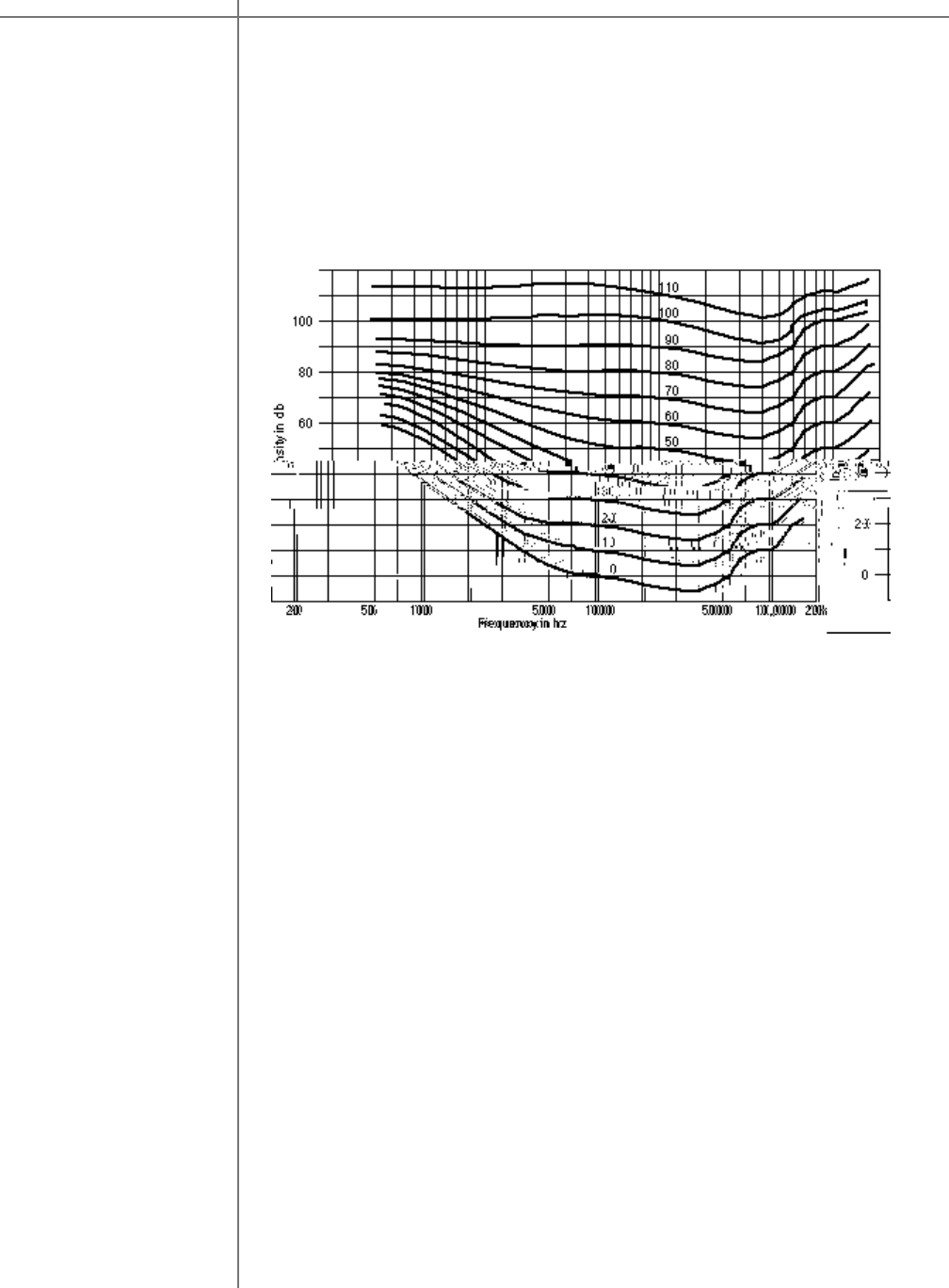
(contours), widely known as Fletcher-Munson equal loudness curves. A sample of
Fletcher-Munson loudness curves is shown in the figure bellow.
On the graph bellow there are 12 curves numbered from 0 to 110. These numbers
represent the loudness level in phons. A Phon is a unit used to describe the
loudness level of a given sound. The reason for introducing the loudness unit is
that two sounds with the same SPL (dB) do not necessarily have the same
perceived loudness. Phon is equal to SPL in decibels at 1000 Hz. For example,
80 phons means as loud as 80 dB, 1000 Hz tone.
CAUTIONCAUTION
10 Tact Audio
M/S-2150 XDRC
Equal loudness curves represent the SPL that different frequencies need to have in
order to be perceived as two tones of equal loudness. For example, a 200 Hz tone
at SPL of 50 dB will have the same perceived loudness as a 1000 Hz tone at SPL
of 40 dB. In this case both 200 Hz and 1000 Hz tones have a loudness of 40
phons, and they both belong to the 40 phons equal loudness curve.
Fletcher-Munson equal loudness curves
As it can be seen from the graph, in comparison to frequencies between 2000 and
5000 Hz, it is intrinsically harder for us to hear very low frequencies (below a few
hundred Hz) and to a lesser extent very high frequencies (above 7000 Hz). At
higher listening levels this difference gradually becomes smaller and smaller and
curves become flatter.
Traditional Tact room correction systems use one target curve that allows for full
range 20-20,000 Hz room corrections. Once selected, the same target curve
(same set of correction filters) was used at all listening levels. This approach did
not take in account the fact that our sound perception, as described by Fletcher-
Munson curves, is frequency and level dependent. Many of our customers have
realized this fact and they have used the nine correction presets (available on all
our RCS products) to program 2.0 S, 2.2 X and TCS MKII with nine different target
curves each corresponding to a different listening level. In this way they were able
to take into account the equal loudness curve effect by switching to new target
curves as the master level changes.
Thus for a number of reasons it is clear that we need a room correction system
that will perform room acoustics correction and at the same time dynamically
change the target curve (correction filters) as the system listening level changes.

11Tact Audio
How does it work?
Dynamic Room Correction (DRC) offers a very sophisticated way of handling a
multi target curve approach to solving equal loudness curve problem. The system
is based on one reference target curve and eight additional target curves called
dynamic target curves. The reference target curve is used to perform basic
reference room correction. Dynamic target curves are labeled 0, -6, -12, -18, -24, -
30, -36 and –42 dB and are combined with the reference target curve to obtain the
final target curve used to calculate correction filters.
For example, if the master level reads –10.3 dB (89.6 on the relative readout) the
system will use the –6 dB and the –12 dB dynamic target curves and by
interpolation will calculate a target curve corresponding to –10.3 dB. After that the
system will combine the 10.3 dB target curve with the reference curve to obtain
the final target curve that is then used to calculate the correction filters. New
correction filters are loaded into the signal path as the music is playing and the
new correction takes effect in a split of a second. The same process repeats
again for any new master level setting.
What is the purpose of the computer interface?
With a DRC system, a computer is used only as a graphical user interface (GUI)
and serves no other purpose. All calculations are performed inside the DRC
processor. Target curves, measurements and other correction parameters are filed
inside DRC flash memory. This approach will allow us to offer other GUI devices
besides window based personal computers.
After target curve modification is made how long does it take
for the new correction to be engaged?
Another main advantage of DRC technology is the elimination of the correction
filters calculation and programming step. If you are current Tact user you are
aware that, after the room measurement waod i .6 n nt waod 0.0006m basic
CAUTIONCAUTION
12 Tact Audio
M/S-2150 X Connections
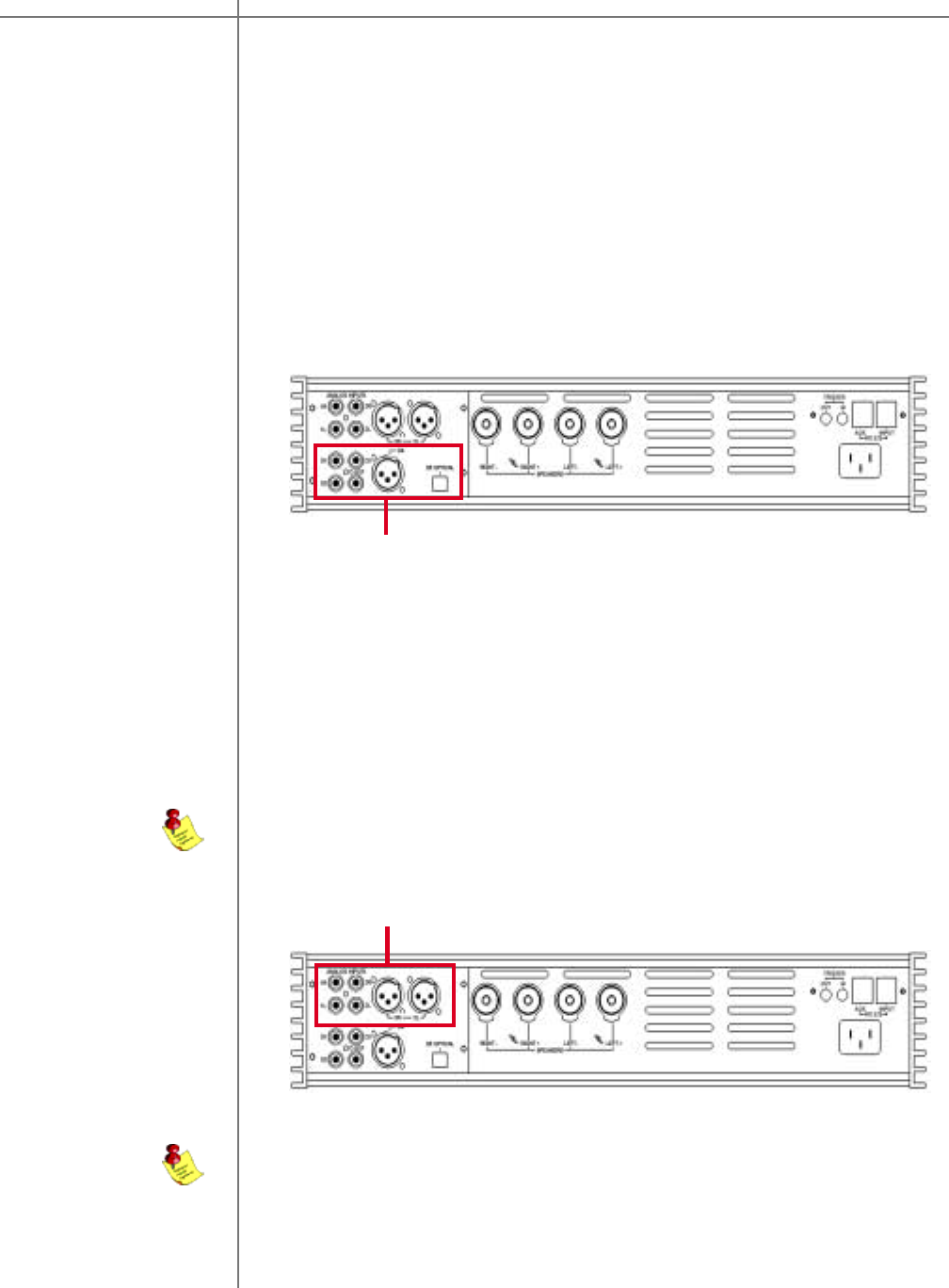
Digital input The M/S-2150 X amplifier has 5 digital inputs:
- three RCA (S/PDIF) ( D1, D2, D3)
- one AES/EBU (XLR) (D4)
- one TosLink (S/PDIF) (D5)
All of the digital inputs support PCM audio data with sampling rates from 32kHz to
96kHz /16-24 bits, however, the AES/EBU and RCA/coaxial inputs support up to
192kHz.
The M/S-2150 X amplifier has 3 stereo analog inputs whith the optional ADC module
installed:
- two analog stereo single ended (RCA) (A1, A2)
- one analog stereo balanced (XLR) (A3)
NOTE: A/D conversion is always performed at 24-bits/96kHz.
Analog input
(optional ADC module)
Digital Input Section
Analog Input Section
NOTE: The optional ADC module is required for analog inputs.
M/S-2150 XConnections
13Tact Audio
Connections
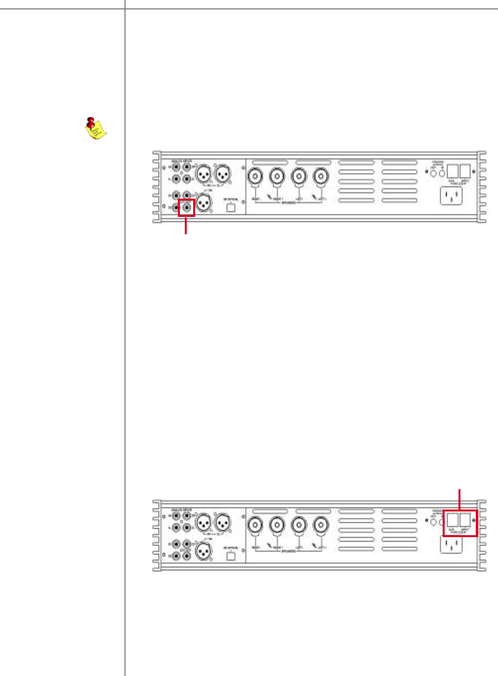
Digital output The M/S 2150 X amplifier has a digital pass through. The digital input signal is passed
to the digital output without processing or volume control. The sampling rate is the
native sampling frequency of the input.
Digital Output
NOTE: that this output is not active when analog input is selected.
RS-232 interface
ports The M/S 2150 X has two RS232 interface ports:
- INPUT
- AUX
Use the INPUT port for communication with your Tact master controller or Personal
Computer.
Use the AUX port to connect to other TacT products. This port should always be
connected to INPUT port of another device.
RS-232 Interface Ports
M/S-2150 X
CAUTIONCAUTION
14 Tact Audio
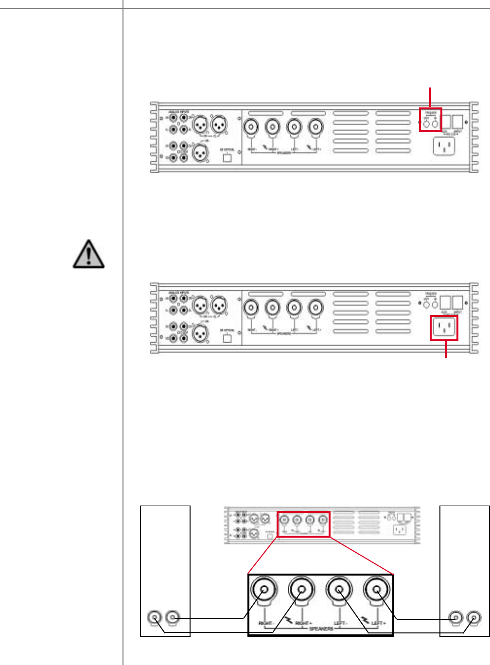
AC mains input Connect the M/S-2150 X to the AC mains wall socket.
CAUTION: Use the supplied IEC mains cable, or a 3-prong grounded cable only.
AC Main Input
Speaker output
(normal operation) The M/S-2150 X amplifier has one pair of high quality speaker terminals. These termi-
nals will accept both spade- and banana-plugs. When connecting your speakers,
please make sure that the RED/HOT terminal is connected to your speakers’ POSI-
TIVE terminal and the BLACK/COLD terminal is connected to your speakers’ NEGA-
TIVE terminal.
RIGHT
SPEAKER LEFT
SPEAKER
+ - + -
The M/S-2150 X has a trigger “IN” and “OUT” to provide on and standby control
from a trigger device and to pass the trigger signal to another device.
Trigger outputs
Trigger Connectors
Connections M/S-2150 X
15Tact Audio
LOW
HIGH
RIGHT
SPEAKER LEFT
SPEAKER
+ -
LOW
+ -
+ -
HIGH
+ -
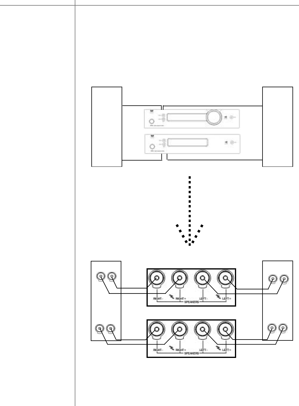
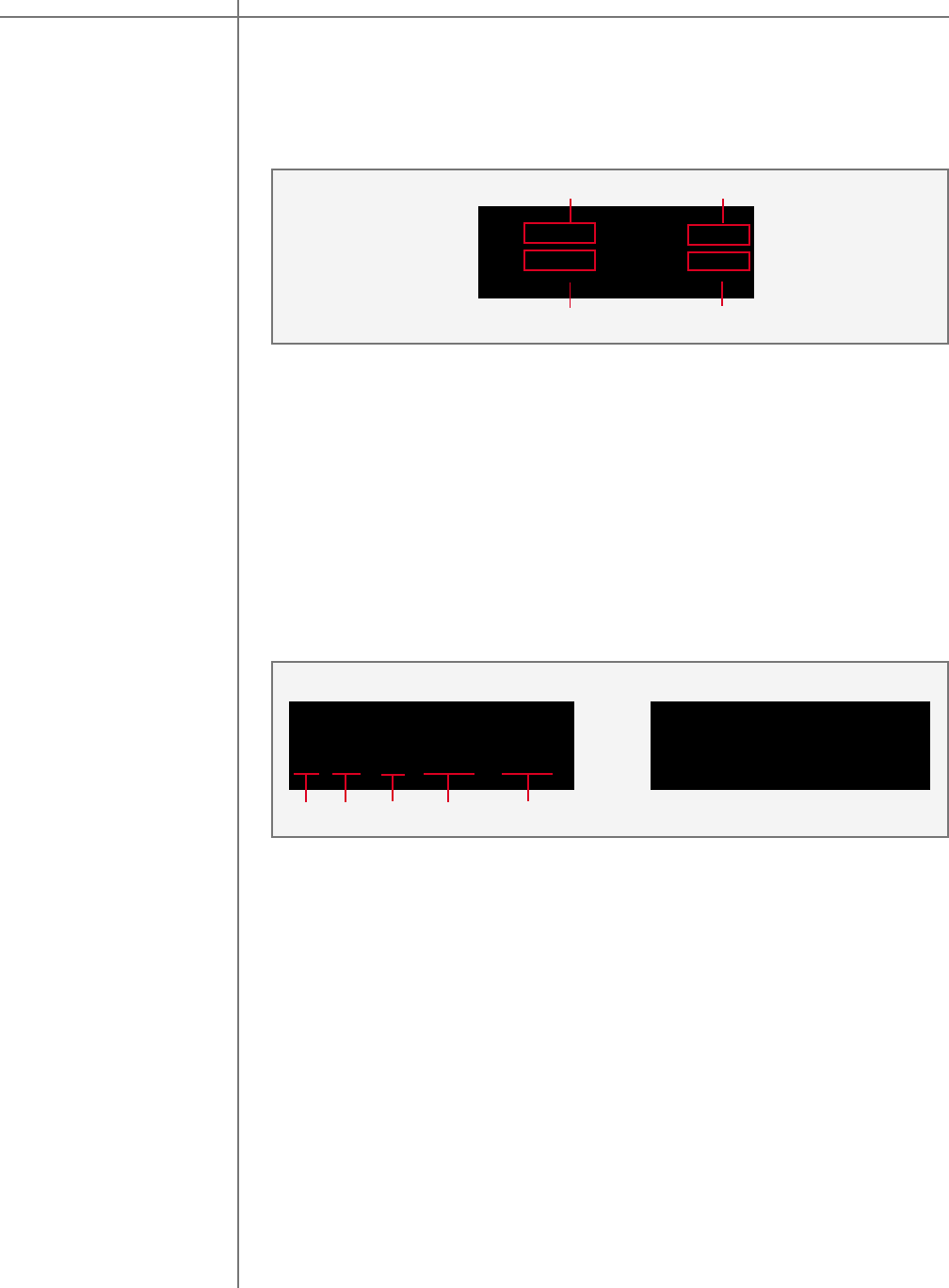
Speaker output
(Biamped operation) If you are using two or more M/S-2150 X amplifiers, and your speakers allow for multi-
amping, you can configure the system to run in biamped, tri-amped or multi-amp
mode. This type of setup allows for one amplifier channel to drive a specific driver or
frequency region. The most commonly used setup is biamped (two channels to each
speaker: high and low frequency range). The following are two examples of making a
biamped connection:
LOW
HIGH HIGH
LOW
Horizontal Biamping LEFT
SPEAKER RIGHT
SPEAKER
Connections M/S-2150 X
CAUTIONCAUTION
16 Tact Audio
LOW
HIGH
+ -
LOW
+ -
+ -
HIGH
+ -
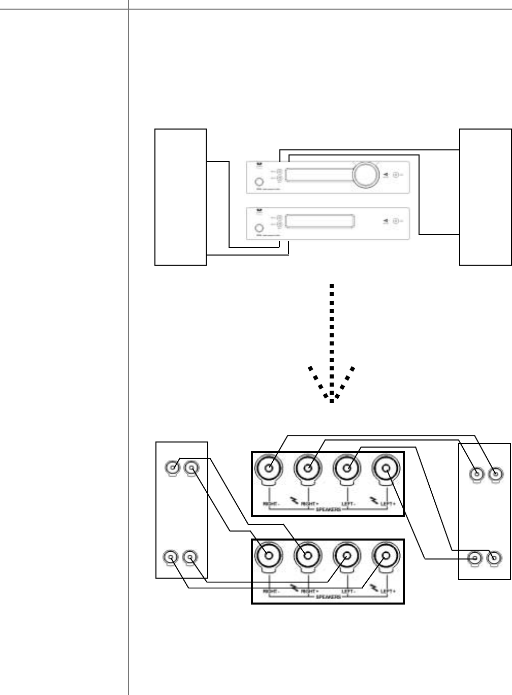
RIGHT
SPEAKER LEFT
SPEAKER
Vertical Biamping
HIGH
LOW
LOW
HIGH
LEFT
SPEAKER RIGHT
SPEAKER
Connections M/S-2150 X
17Tact Audio
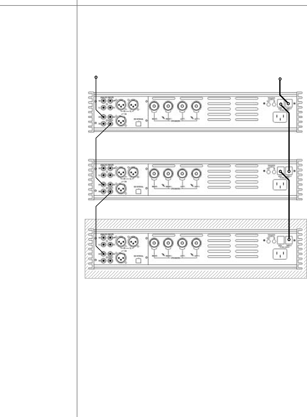
Biamping - continued When two or more M/S-2150 X amplifiers are configured in a bi-/tri-amped setup, both
the signal and the RS232 TacT System Bus must be daisy chained between the
amplifiers.
The same signal flow is applicable for both horizontal and vertical bi-amping.
From RCS2.0S, RCS2.2X or
TCS mkII *Optional
From source
AMP-1
AMP-2
AMP-3 - ONLY PRESENT IN TRI-AMPED SETUP
RS232
RS232
RS232
Digital signal
(coax/SPDIF)
Digital signal
(coax/SPDIF)
Digital signal (coax/SPDIF)
usually CD player output.
Connections
With its advanced DSP control, the M/S-2150 X can enable digital crossovers
package (high-pass, low-pass and band-pass) making it possible to configure M/
S-2150 X amplifiers to virtually fit any loudspeaker system.
Examples of how a TacT active system can be configured:
1) Active two-way. The M-2150 X operates as master amp (control unit) and the
S-2150 X operates as normal/slave amp. M-2150 X has a DSP-based high-pass
filter and drives the high-section of the 2-way loudspeaker system. S-2150 X has
a low-pass filter and drives the bass-section of both loudspeakers.
2) Active three-way. Amp 3, M-2150 X (master unit) is set to implement a high-
pass filter and drives the tweeter section. Amp 2 (normal/slave), S-2150 X is set
to implement a band-pass filter and drives the midrange section. Amp 1 (normal/
slave), S-2150 X is set to implement a low-pass filter and drives the bass sec-
tion.
M/S-2150 X
Configurations
M/S-2150 X
CAUTIONCAUTION
18 Tact Audio
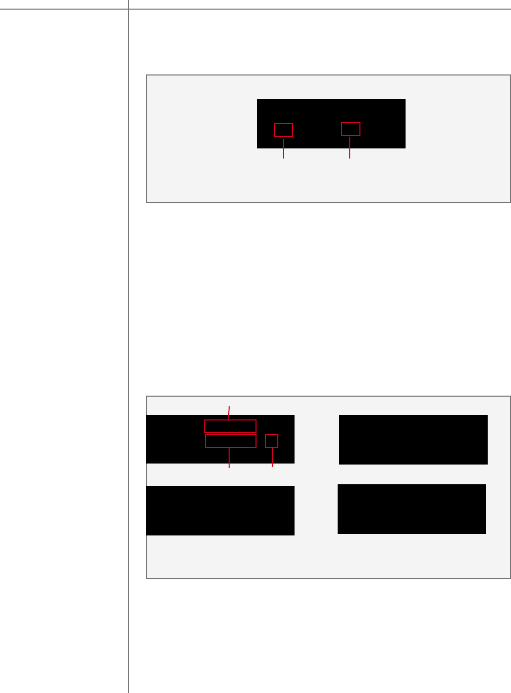
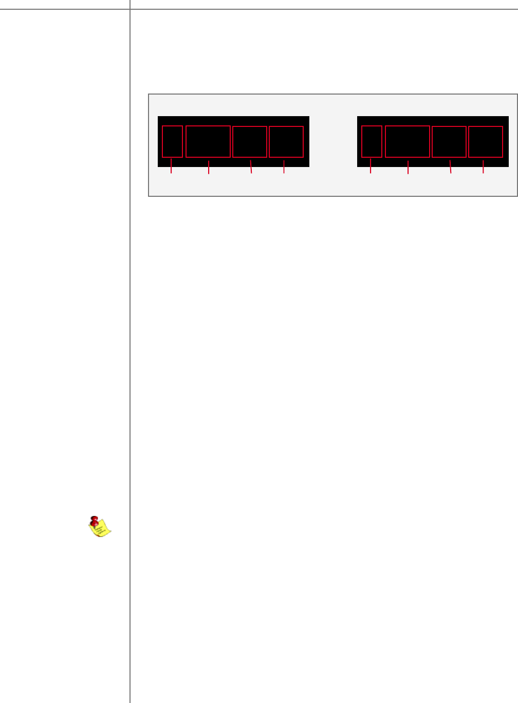
Front Panel Controls
ON/OFF Use the “ON/OFF” switch to toggle between ON and OFF operation.
(Standby mode can be selected only through the remote control)
Master volume The master volume is controlled by turning the large volume wheel. The green num-
bers on the left side of the wheel will change as you turn the wheel - this is your
master volume level indicator. Master level is displayed on the Volume Level display
and on the Main Display. Volume Level display shows master level in relative
numbers with 99.9 corresponding to the maximum level and 0.0 corresponding to the
minimum level. Main Display shows master level in dB’s with 0 dB corresponding to
the maximum level and -99.9 dB corresponding to the minimum level. The wheel
sensitivity, maximum volume and other settings can be found in the “OPT” menu.
S-2150 X master volume can be controlled only by the supplied remote control. M/S-
2150 X master volume can be controlled via RS232 connection.
Mute Use the “MUTE” button to mute or un-mute during playback. The master level indica-
tor will switch to “--” in Mute mode. You can still adjust the master volume while the
unit is in Mute mode - the master level indicator on the Main Display will show
current master level in dB’s.
Digital
input selector
Analog
input selector
Press the “DIGITAL” button to select the digital input. This is a toggle switch, and
pressing it multiple times will toggle through all of the five digital inputs. The selected
input will be displayed in the input display portion of the display screen.
Press the “ANALOG” button to select the ANALOG input. This is a toggle switch, and
pressing it multiple times will toggle through all of the three analog inputs. The
selected input will be displayed in the input display portion of the display screen.
NOTE: The optional ADC module is required for analog inputs.
The front panel controls on the 2150 X amplifier will allow you to control all of the
amplifiers main features. All secondary options are controlled with menus using the
remote control or the supplied software. The exclusive “TacT wheel” is the master
volume control. (The wheel is only available on the M-2150 X)
ON/OFF Switch
MuteMaster VolumeDigital Input Selector
Main Display
Analog Input Selector
Input Display Volume Level
M/S-2150 XFront Panel
19Tact Audio
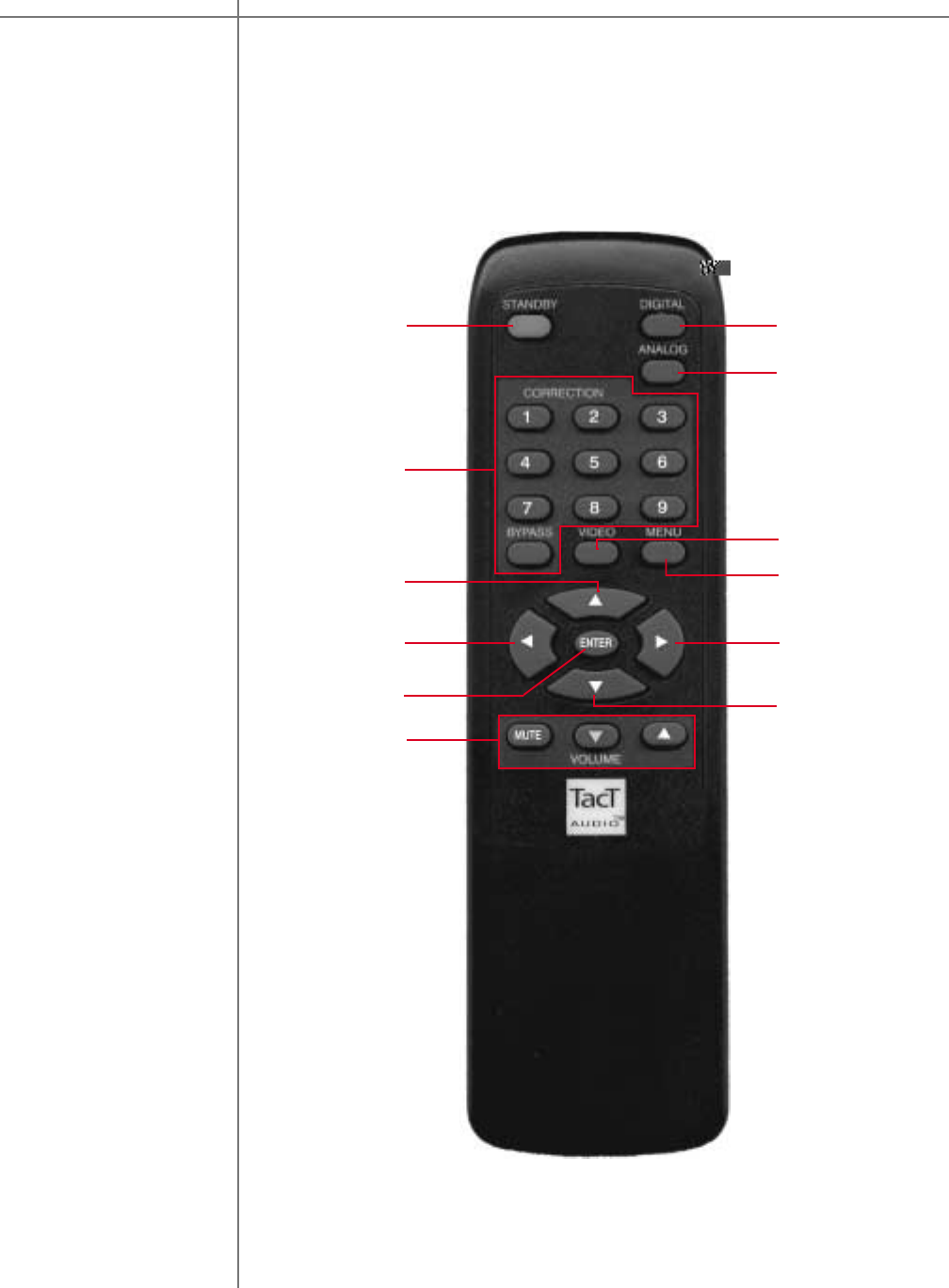
The remote control is used to access the front panel display controls and menus.
Remote Control
4
11
2
9
1
3
5
6
7
10
8
12
Remote Control M/S-2150 X

CAUTIONCAUTION
20 Tact Audio
1 - STANDBY
The STANDBY button will turn the M/S 2150 X “ON” or it will place it into
“STANDBY” mode. When in standby mode, the unit is placed into a low power
“idiling” state. The standby button is also used to save changes that were made in
the menu editing parameters. By placing the unit into standby the current settings
are saved.
2 - DIGITAL
The DIGITAL button will scroll sequentially, allowing the selection of one of the 5
digital inputs.
3 - ANALOG
The ANALOG button will scroll sequentially, allowing the selection of one of the 3
analog inputs.
4 - CORRECTION block
The CORRECTION block buttons are inactive with this unit.
5 - MENU
The MENU button will switch the front panel display from the status screen to the
main menu screen.
6. VIDEO
The VIDEO button is inactive with this unit.
7. UP
The UP navigational button is used to select menu options and/or change their
values.
8. DOWN
The DOWN navigational button is used to select menu options and/or change their
values.
9. LEFT
The LEFT navigational button is used to select menu options and/or change their
values.
10. RIGHT
The RIGHT navigational button is used to select menu options and/or change their
values.
11. ENTER
The ENTER button will select the menu option currently marked by the blinking
cursor or is used to enter an edited parameter.
12. VOLUME Block
The VOLUME block consists of three buttons.
The “MUTE” button will mute/un-mute all enabled channels.
The “UP” button will increase the master volume level
The “DOWN” button will decrease the master volume level.
Remote Control M/S-2150 X
21Tact Audio
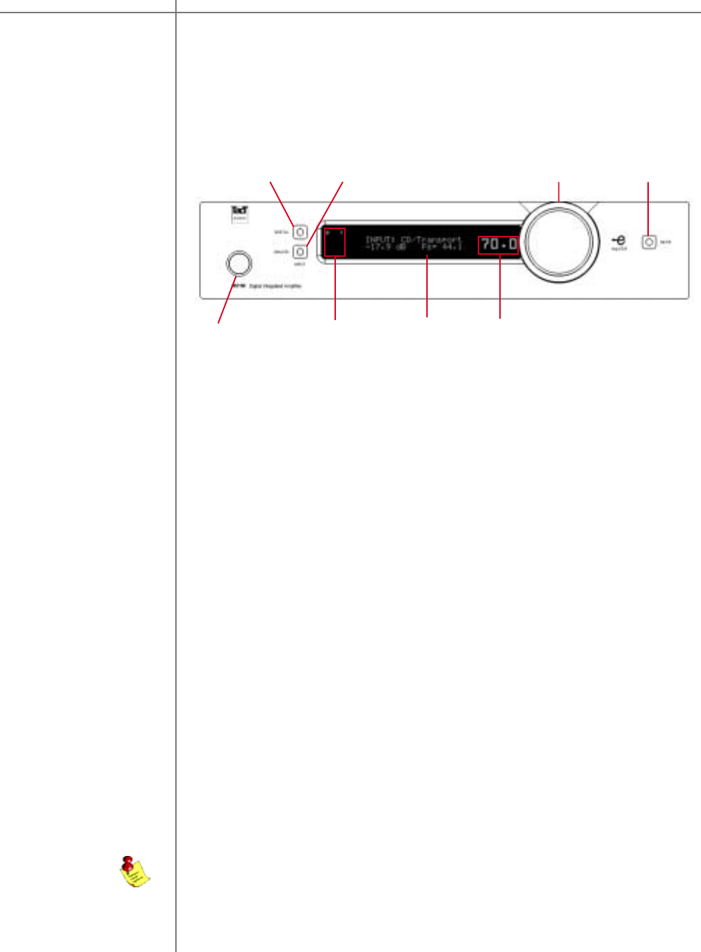
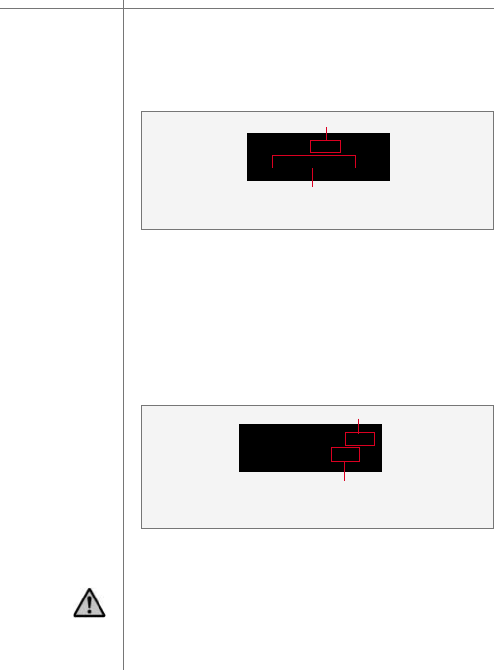
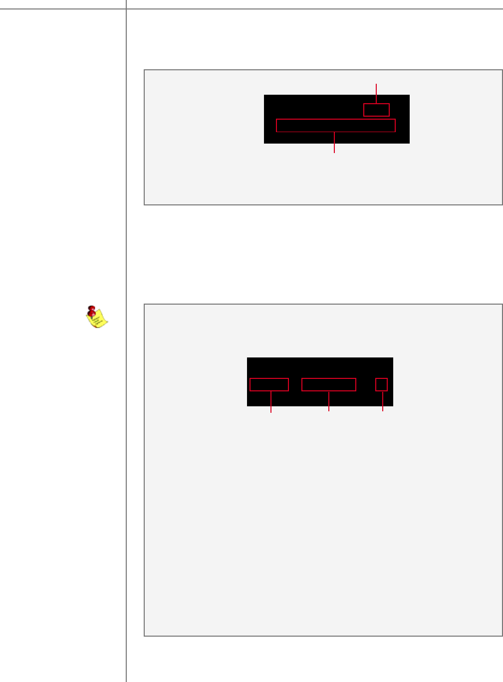
Front Panel Display
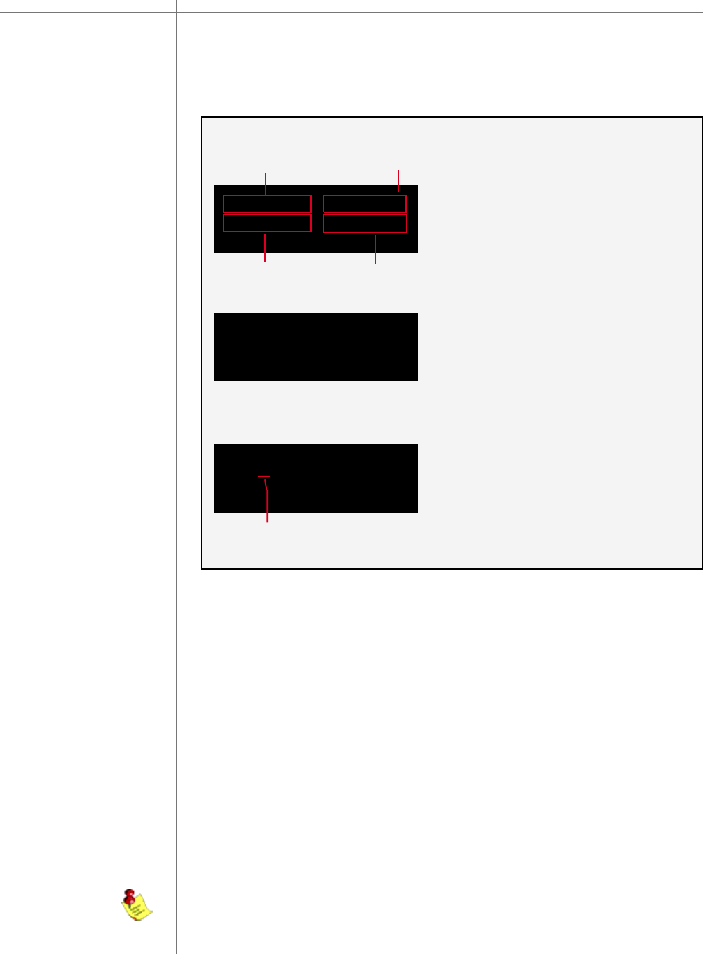
Main screen When the M/S-2150 X amplifier is turned ON and the system loading sequence has
completed, the amplifier will display the main screen.
3
2
1
Main Screen
CRO:>BP * EQ: BP *
-17.9 dB Fs= 44.1
RCS:>BP * EQ: BP *
-17.9 dB Fs= 44.1
CRO Mode
4
1 - Displays mode and preset selection as set in the MODE and DRC menu. This
field displays CRO if CRO mode is selected. It will display RCS if RCS or RCS-
SUB mode is selected and DRC menu option is set to OFF. It will display DRC if
RCS or RCS-SUB mode is selected and DRC menu option is set to ON.
2 - Displays current parametric equalizer preset.
3 - Master level in dB
4 - Input sampling frequency indicator.
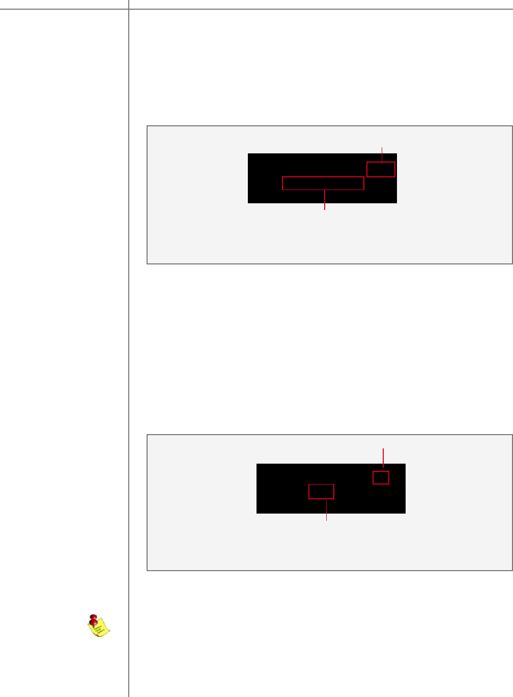
Main screen
Selecting Presets
Use remote control LEFT and RIGHT buttons to place the screen pointer, labeled with
“>” character (field 5), into field 1 for CRO or RCS/DRC preset selection or into field 2
for ParEq preset selection. When screen pointer is placed in field 1 then use remote
control CORRECTION buttons to select CRO, or RCS/DRC preset. When the screen
pointer is placed in field 2 use remote control CORRECTION buttons to select ParEq
preset.
DRC:> 1 * EQ: BP *
-17.9 dB Fs= 44.1
RCS or RCS-SUB Mode
MODE menu option is set to CRO mode. M/
S-2150 X operates in crossover mode. CRO
menu option is enabled and RCS, MSR,
DRC and DOPT menu options are disabled.
MODE menu option is set to RCS or RCS-
SUB mode. M/S-2150 X operates in room
correction mode. CRO menu option is
disabled and RCS, MSR, DRC and DOPT
menu options are enabled. DRC menu option
is set to OFF
MODE menu option is set to RCS or RCS-
SUB mode. M/S-2150 X operates in room
correction mode. CRO menu option is
disabled and RCS, MSR, DRC and DOPT
menu options are enabled. DRC menu option
is set to ON
RCS or RCS-SUB Mode
5
M/S-2150 X can support either room correction or crossover feature. Room
correction and crossover features can NOT be used at the same time.
M/S-2150 XMain Screen
CAUTIONCAUTION
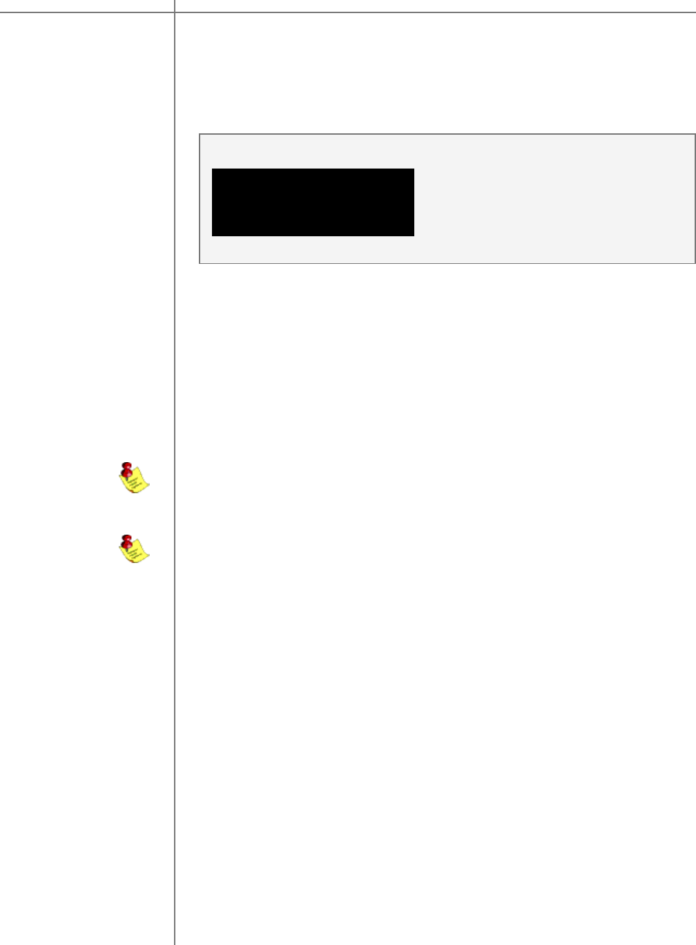
22 Tact Audio
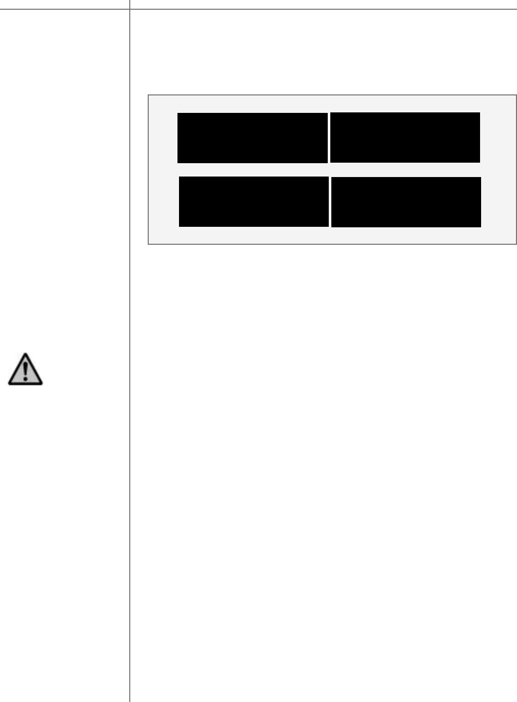
The Main menu of the M/S 2150 X has three pages of general menu selections.
<- CRO PAREQ MODE
OPT DISPL REM ->
MAIN menu
<- COMM ADDR ADC
LOCK GAIN TRIG ->
DELAY LEVEL POL
InOut RCS MSR->
Saving Menu
Settings Custom settings that are made to any of the menu selections may be permanently
saved by placing the M/S-2150 X into standby mode. If you make changes to any of
the menu items and turn the unit off before placing it into standby mode all settings
will be lost. To place the M/S-2150 X into standby mode press the red “STANDBY”
button on the remote control.
Main Menu
The remote control is needed to enter the amplifiers Menu selection pages. Press
the MENU button to enter the amplifiers menu section. Use the LEFT and RIGHT
buttons to highlight an option with the selection cursor. To enter a highlighted op-
tion press the ENTER button. Once you are in a menu option use the MENU but-
ton to go back one step (from sub-menus) or to return to the main screen.
<- VER MIC DRC
DOPT
M/S-2150 XMain Menu
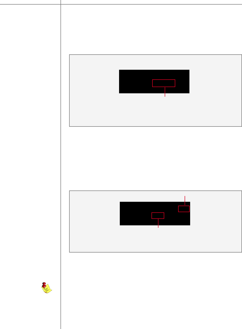
23Tact Audio
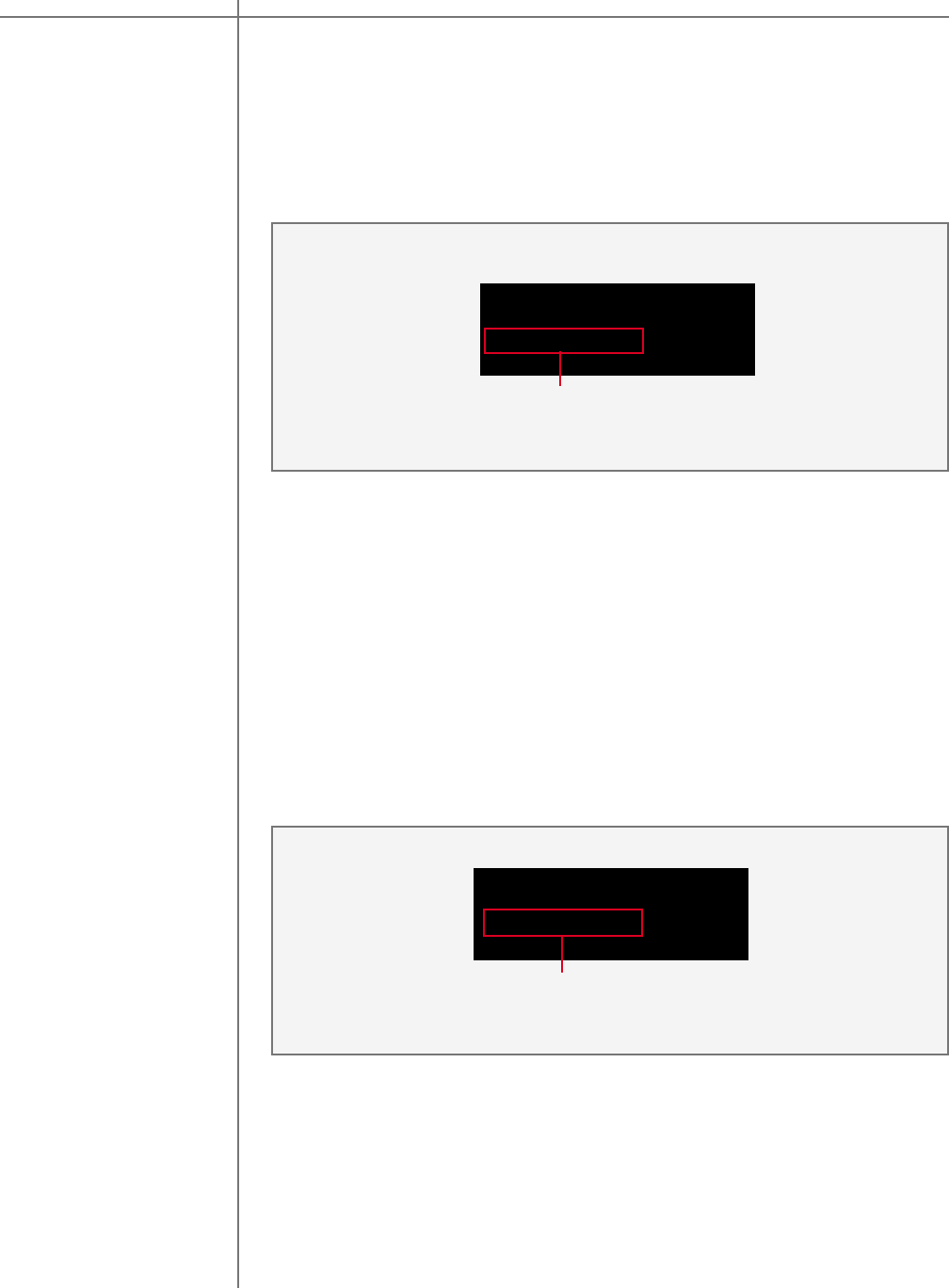
.
The Delay menu controls the system’s time alignment. The system’s time align-
ment can be adjusted by changing the delay time for the left and right outputs inde-
pendently.
DELAY menu
LEFT RIGHT
0.00 0.00 msec
1
1 - Left and Right channel delay time settings.
Delay Menu
LEVEL menu
LEFT RIGHT
0.0 0.0 dB
1
The Level menu controls channel balancing. You can adjust the system’s bal-
ance by changing the attenuation for the left and right output signals indepen-
dently.
1 - Left and Right channel level settings.
Level Menu
Use LEFT and RIGHT navigational buttons to highlight an option and use UP and
Down buttons to change its value . The maximum delay time value that can be
set is 31.95 msec (0.03195 seconds). Sound waves travel a distance 1 foot for ap-
proximately 1 msec. A unique delay time can be assigned to each crossover and
correction preset. In the CRO mode delay times can be adjusted manually. In the
RCS/DRC mode delay times can be adjusted manually or automatically as set in
DOPT menu. In any operating mode delay time resolution is approximately 10.42
micro seconds (0.00001042 seconds).
Use the LEFT and RIGHT navigational buttons to highlight an option and use the
UP and Down buttons to change its value . A unique channel level can be assigned
to each crossover and correction preset. Channel level can be changed in steps of
0.1 dB.
Main Menu Options M/S-2150 X
CAUTIONCAUTION
24 Tact Audio
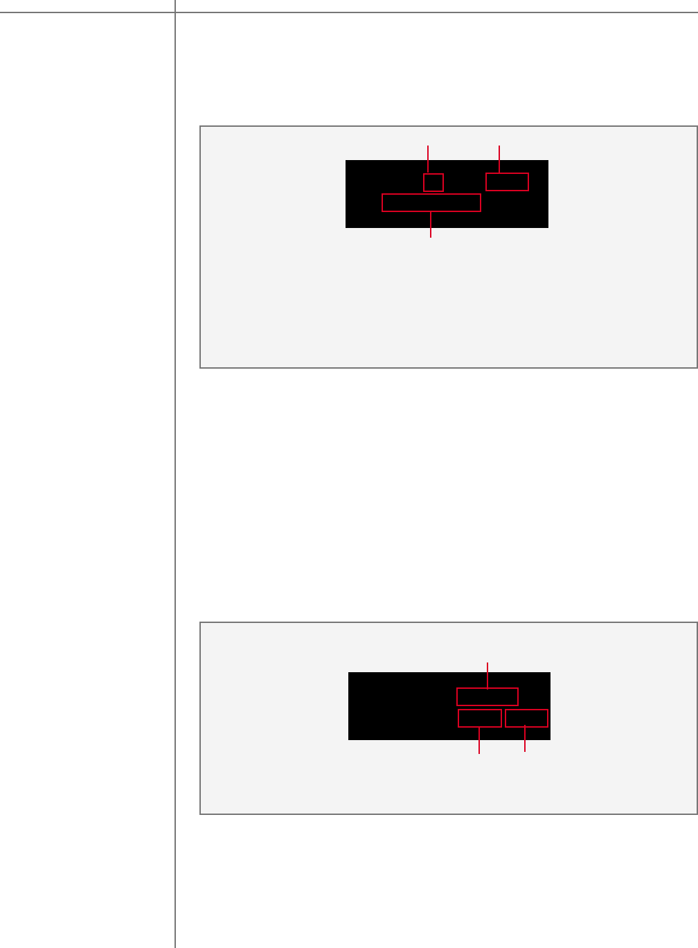
InOut Menu Use this screen to set M/S-2150 X internal signal routing. Use UP and DOWN
buttons to scroll through four possible input source combinations. To select
displayed option press ENTER button. Active selection is indicated by “*” displayed
next to it. This feature is useful for systems that use multiple of amplification
channels per loudspeaker.
The figure bellow lists all four possible combinations of the input signal assignment to
output channels.
To highlight an option use the LEFT or RIGHT buttons. To selected highlighted option
use the UP , DOWN of ENTER buttons. A unique channel polarity can be assigned to
each crossover and correction preset.
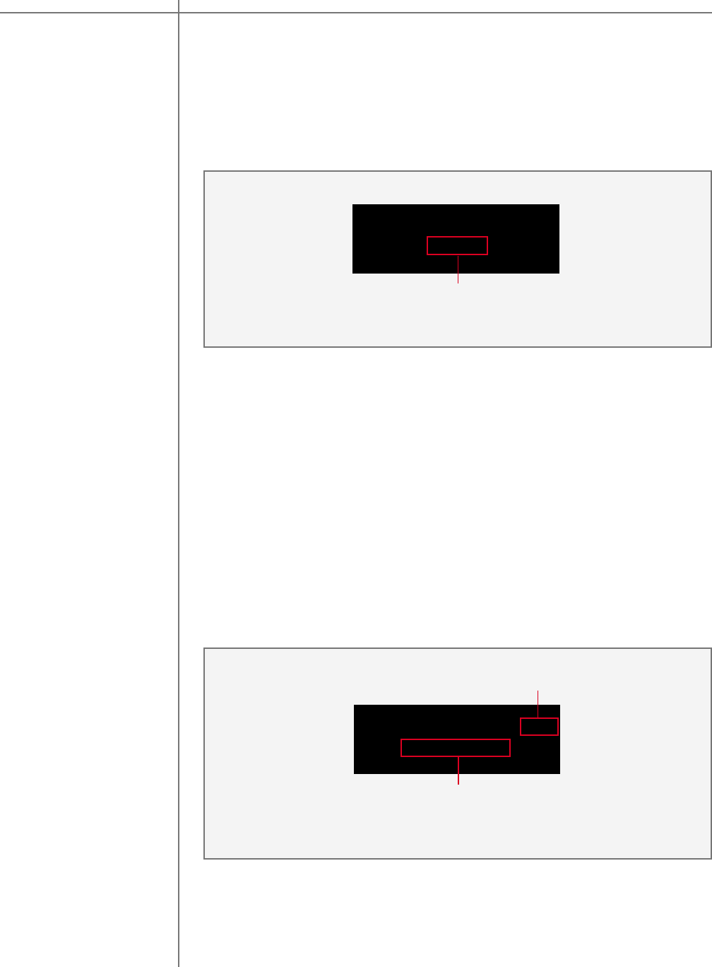
POL menu
(Polarity)
LEFT RIGHT
+ +
1 - Left channel polarity setting.
2 - Right channel polarity setting.
Use this menu to set channel polarity. Each channel can be set to + (non inverted) or
- (inverted) polarity.
Polarity Menu:
OUTPUT: L R
SOURCE: L L *
1
InOut Menu:
3
2
2
OUTPUT: L R
SOURCE: L R *
OUTPUT: L R
SOURCE: R R *
OUTPUT: L R
SOURCE: R L *
1 - Source selections for output.
2 - Fixed output speaker posts.
3 - Active source selection.
The first screen, going from left to right, assigns left input to left output and right input
to right output channel. Second figure assigns left input channel to both left and right
output channels. Third figure assigns right input channel to both left and right output
channels and the fourth figure assigns right input to left output and left input to right
output channel.
1
M/S-2150 XMain Menu Options
25Tact Audio
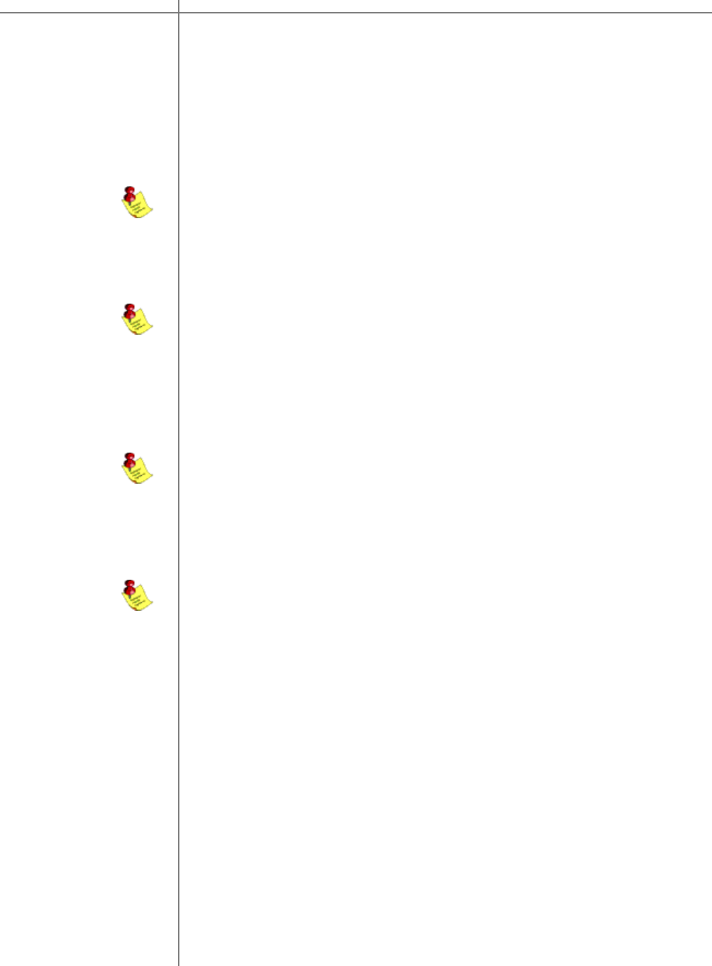
RCS Menu Use this menu to select one of the correction presets. M/S-2150 X offers 9 correc-
tion presets as well as bypass. This screen is enabled only if RCS or RCS-SUB
mode is selected (see MODE menu). Correction names are user programmable
from M/S-2150 X windows based application program..
Use this menu to select digital microphone input. Digital microphone input is nor-
mally connected to one of BOZ RCS-16M digital outputs. If microphone is not used
set this option to “---”. In order to avoid positive feedback from the microphone in-
put, selected microphone input can not be used as standard digital input signal..
Use the “UP” and “DOWN” buttons to scroll through all possible options. To select
displayed option press “ENTER” button.
RCS 1: Corr #1
1: Corr #1
1
1 - Correction preset selections.
2 - Active correction preset.
RCS Menu : 2
MEASUREMENT CH: D1
SELECT CH: D1
MSR Menu :
Use the “UP” and “DOWN” buttons to scroll through all possible options. To select
displayed option press “ENTER” button.
To avoid the possibility of getting positive feedback, after the measurements are
completed disconnect microphone from M/S-2150 X input. Positive feedback can
result in excessive output signal level that could potentially damage connected
loudspeaker system.
1 - Measurement input selection.
2 - Edit selected measurement input.
1
2
MSR menu
Main Menu Options M/S-2150 X
CAUTIONCAUTION
26 Tact Audio
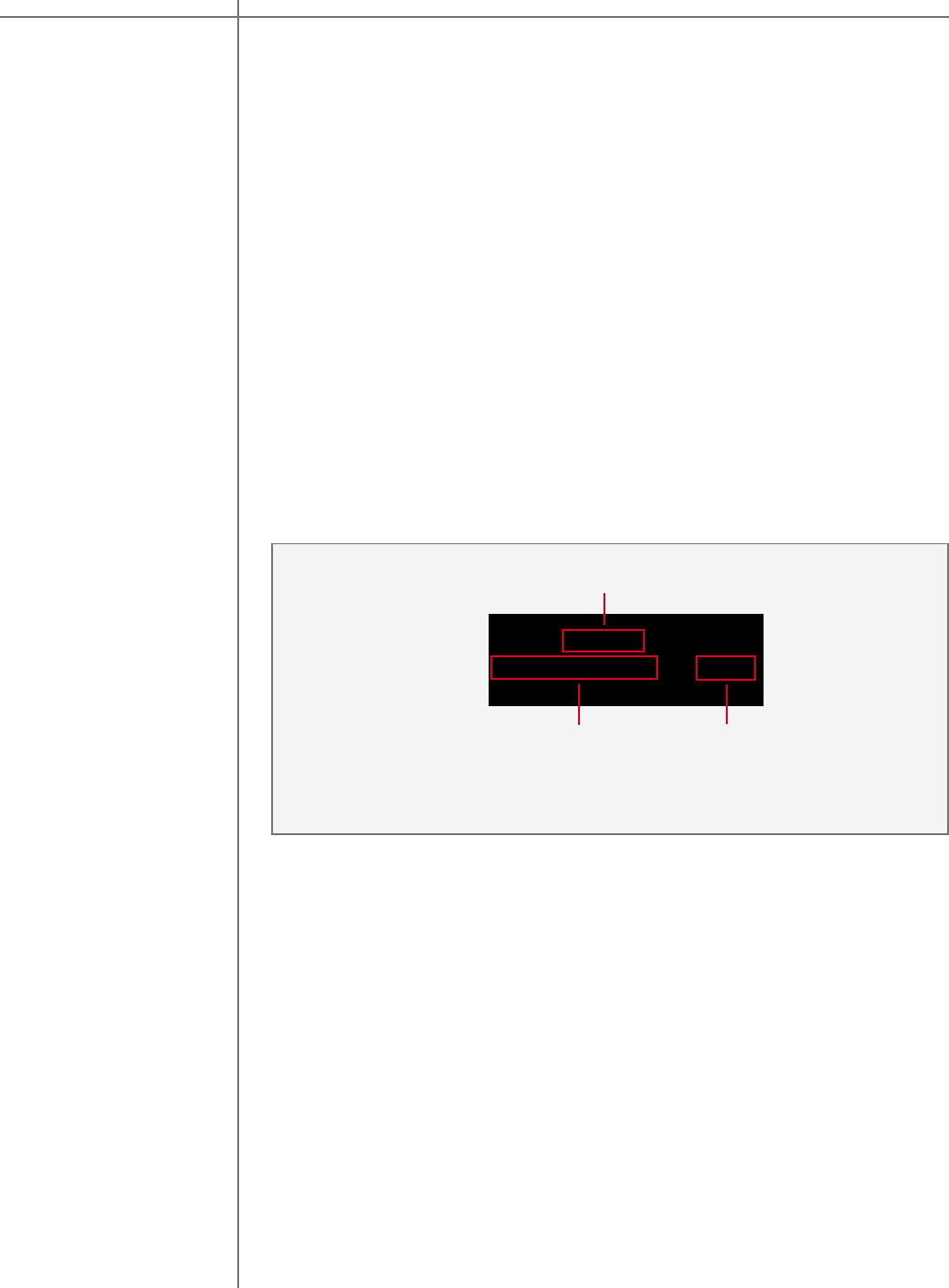
CRO menu
CRO: Bypass
1: Preset #1 EDIT
CRO Menu :
Use LEFT and RIGHT buttons to place screen cursor over Preset nad EDIT op-
tions.
Use UP and DOWN buttons to scroll through all possible CRO presets. To select/
engage displayed preset press ENTER button. Selected CRO preset will be dis-
played on the first line of the screen.
For more details on how to use CRO screen please refer to M/S-2150 X
Crossover Package section.
This menu option is disabled if in MODE menu option RCS or RCS-SUB mode is
selected.
The CRO menu is used to select CRO presets and edit their values. You can se-
lect BUTT (Butterworth filter type) or BUTTSQ (Butterworth squared filter type) and
edit HP, LP or BP filters. This menu is only accessible when CRO mode is se-
lected (see MODE menu option).
If M/S-2150 X is not used to provide active crossover filtering CRO menu option
should always be set to BYPASS.
Main Menu Options M/S-2150 X
To enable this screen set MODE
menu screen to CRO option.
27Tact Audio
PAREQ
PAREQ PRESET: BP
PR: 1 LEFT RIGHT
PAREQ Menu
Parametric EQ menu is used to apply up to twelve bands of parametric equaliza-
tion per output channel.
Use LEFT or RIGHT buttons to move the screen cursor to fields 1,2 and 3.
1 - When the screen cursor is in this field use UP/DOWN buttons to scroll through all
possible ParEq presets. To select/engage displayed ParEq preset press ENTER
button. Selected ParEq preset will be displayed in field 4.
2 - When the screen cursor is in this field press ENTER button to edit left channel
ParEq parameters of the ParEq preset displayed in field 1. This option is disabled
if BP is displayed in field 1.
3 - When the screen cursor is in this field press ENTER button to edit right channel
ParEq parameters of the ParEq preset displayed in field 1. This option is disabled
if BP is displayed in field 1.
4 - This field displays current/active ParEq preset.
3
12
4
ParEq feature can simultaneously run with the crossover and room correction pack-
age. To disable ParEq select BYPASS (BP) for ParEq preset.
Main Menu Options M/S-2150 X
CAUTIONCAUTION
28 Tact Audio
LF LEV FR OCT
1 -12.2 1400 0.29
3
12 4
LEFT Edit Menu RIGHT Edit Menu
RF LEV FR OCT
1 -12.2 1400 0.29
3
12 4
PAREQ Editing To edit ParEq parameters in ParEq MENU screen select LEFT to edit left channel
parameters or RIGHT to edit right channel parameters. Depending on the selection
one of the following screens will be displayed:
Use LEFT or RIGHT buttons to move the screen cursor to fields 1,2,3 and 4.
1 - When the screen cursor is in LF/RF (LF-left channel filter, RF-right channel filter)
field use UP/DOWN buttons to scroll through all 12 ParEq filters. Note that as
you scroll through the filters, ParEq parameters in fields 2,3 and 4 will keep
changing as they display parameters that correspond to filter number as
displayed in field 1.
2 - LEV field displays signal gain/attenuation that corresponds to the filter number as
displayed in field 1. Filter level can be set anywhere between +12.0 dB to -18.0
dB in increments of 0.1 dB. If this field is set to 0 dB that particular filter has no
effect on the audio signal. Positive values greater than 0 dB in this field indicate
that that particulat filter will amplify audio signal at and around filter frequency as
set in field 3.
3 - FR field displays filter frequency that corresponds to the filter number as
displayed in field 1. Filter frequency can be set anywhere between 15 Hz and 20
KHz with resolution of 1 Hz. If LEV parameter is set to 0 dB the value of this fiels
is irelevant.
4 - OCT field displays filter width given in octaves. Octave parameter is calculated as
1/Q-factor.
It is possible that in some cases ParEq filter settings can cause the system to en-
ter audio signal clipping region. Audio signal clipping will produce harmonic distor-
tions that could be quite audible. The probability of this happening increases with
the amount filter LEV parameter. Clipping can occur only if LEV parameter is posi-
tive (signal gain). Clapping cannot occur if LEV parameter is set to negative values
(attenuation).
ParEq Menu Options M/S-2150 X
29Tact Audio
- Max Level controls the system’s maximum signal level. For example:
if this option is set to -3.0 dB, the volume control and output can not go
above -3.0 dB.
- DTHR sets the signal detection threshold. If the absolute value of the
Left or the Right channel signal goes above this threshold
the red signaling dot will be displayed on the front panel bellow the
master volume display. This feature can be used to indicate signal pres-
ence on either channel or to indicate near clipping condition. To use it
as signal presence indicator set DTHR to a value close to -90.0 dB. To
use it as near clipping indicator set DTHR to a value close to 0.0 dB.
- WH option sets the wheel sensitivity. The maximum speed is 10 and
minimum speed is 1. For example if the speed is set to 1, the volume in-
crease is slower than if set to 10. To turn the wheel off, set the speed
setting to “--”. This setting is located one step below “1” the minimum
speed.
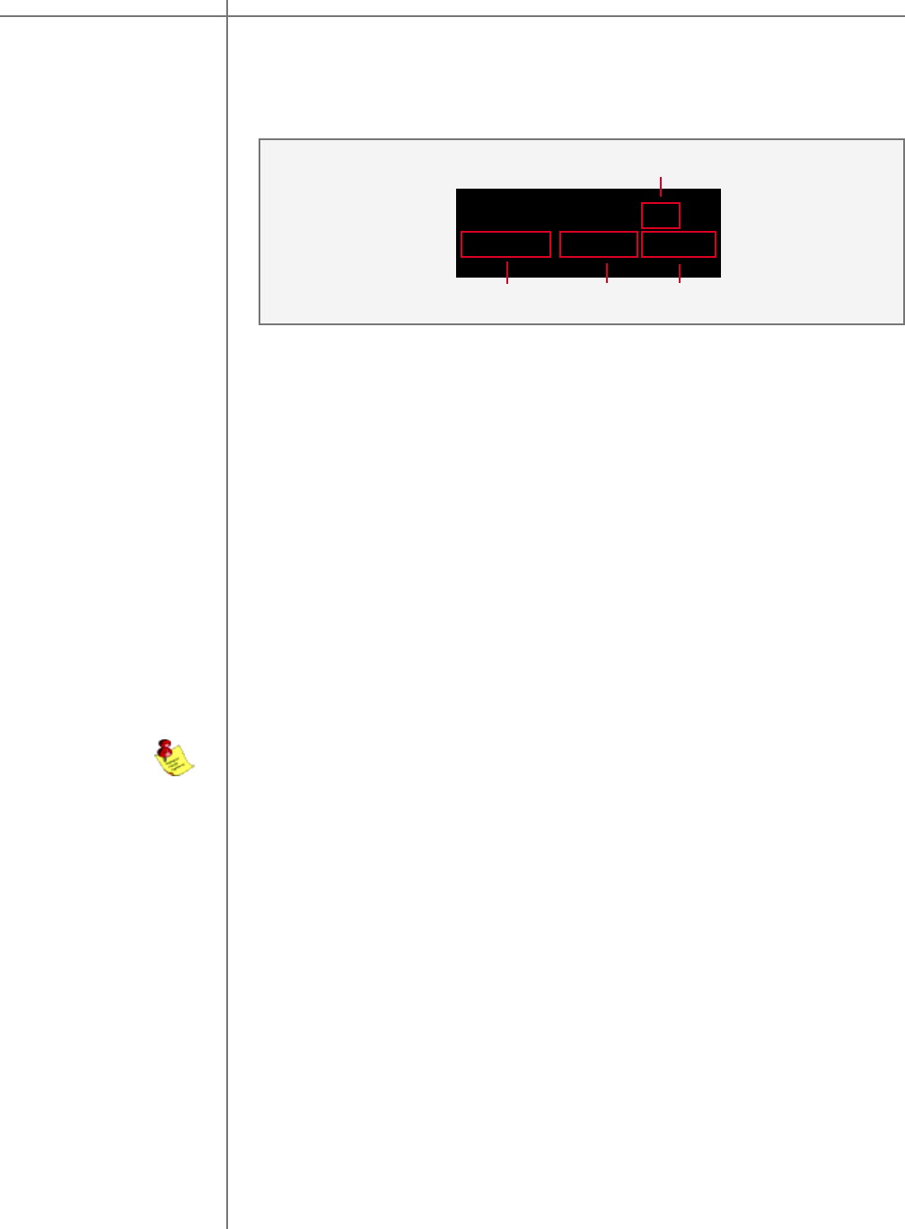
OPT menu
(Options) The options menu is designed to control the systems maximum signal level
MAXLEV, signal detection threshold DTHR and wheel speed WH.
MAXLEV DTHR WH
+12.0 -6.0 dB 5
Options Menu
1 - Maximum Level setting.
2 - Detection setting.
3 - Wheel speed setting.
13
2
To select/highlight an option use the LEFT or RIGHT buttons. To modify a selected
option use the UP and DOWN buttons.
NOTE: Wheel speed is only available on the M2150 X.
Mode menu
Use the LEFT and RIGHT buttons to highlight the desired option and select it by
pressing the ENTER button.
The Mode menu allows for selection of M/S-2150 X operating mode. If RCS mode
is not used the unit should always be set to CRO mode.
CURRENT MODE: CRO
CRO RCS RCS-SUB
1 - Display Mode selections.
2 - Active Mode setting.
1
2
Main Menu Options M/S-2150 X
CAUTIONCAUTION
30 Tact Audio
DISPL menu
(Display)
REM menu
(Remote)
Display Timeout OFF
OFF ON
DISPL Menu
1 - Display Timeout selections.
2 - Active Display Timeout setting.
2
1
The display menu controls the display Time-Out feature. This option is used to
turn the front panel display ON or OFF. When this option is set to ON the front
panel timer will turn the front display off if the front panel has not been accessed for
more than 10 seconds. To wake the display, simply turn the wheel or push any but-
ton either the front panel or the remote control. When this option is set to OFF the
display will remain lit whenever the unit is on.
Use the LEFT and RIGHT buttons to highlight the desired option and select it by
pressing the ENTER button.
REMOTE CONTROL: ON
OFF
1 - Indicates that remote is ON.
2 - From this menu remote control can only be turned OFF
REM Menu
The remote menu allows for disabling the remote control. Once the remote control
is disabled the unit can only be controlled from the front panel. An alternate way to
enable or disable the remote control is to press the front panel “ANALOG” and
“DIGITAL” buttons simultaneously- this can be used to change the remote control
state without entering the REM menu.
Press ENTER button to disable remote control.
Remote control is automatically disabled when M/S-2150 X detects an incoming
RS232 signal.
1
2
Main Menu Options M/S-2150 X
31Tact Audio
COMM menu
(Communication) Use this menu to enable MASTER or NORMAL communication mode. In the MAS-
TER mode M/S-2150 X will send master volume and mute changes as well as
standby/ON status to all M/S-2150 X units connected to AUX RS232 port. Note
that only one unit can be configured as MASTER and all others must be configured
as NORMAL units - slaves.
BAUD RATE: 57600
CONTROL: NORMAL
Communication Menu
1
Use the ENTER button switch between MASTER and NORMAL. M/S-2150 X has
fixed baud rate of 57600.
1 - Master/Normal control setting. (M2150 ONLY)
ADDR menu
(Address)
To each M/S-2150 X unit connected to the same RS232 control chain a unique de-
vice address has to be assigned. Device address can be set to any number be-
tween 1 and 255. Factory default device address setting is “001”
Use UP and DOWN buttons to select desired device address and then press EN-
TER button to select it.
Address Menu
1 - Address settings.
2 - Active address setting.
Current Address: 1
ADDRESS: 1
1
2
To permanently save device address in M/S-2150 X internal memory you must
place M/S-2150 X into stand by mode.
Main Menu Options M/S-2150 X
CAUTIONCAUTION
32 Tact Audio
ADC menu
(ADC module optional)
1 - Assignable gain values.
2 - Input channel currently selected.
3 - Active gain setting for selected input channel.
ADC Menu
The M/S-2150 X may be equipped with an optional state of the are Analog to Digital
Converter. To further enhance the converter’s performance, the system offers two
selectable gain values for the ADC input stage. These two values may be assigned
to each input independently.
To select an analog Input (2) use the ANALOG selector button found on the M/S-
2150 front panel or on the remote control to scroll to the input you would like to
edit. Use LEFT and RIGHT buttons to highlight desired option and then press EN-
TER to select it.
1
GAIN IN 2: HIGH
LOW HIGH
3
1 - Lock code.
2 - Active lock state.
3 - Set button.
Lock Menu
1
M/S 2150 : LOCKED
PASSWORD : 0000 SET
2
LOCK menu
3
The lock menu allows a lock to be set to prevent entering the M/S-2150 editing
menus without unlocking the M/S-2150 X with the lock code. By default the M/S-
2150 X is unlocked and all menus can be accessed and inputs can be changed
without entering a lock code. When the unit is locked, the only menu option that
can be entered is the LOCK menu to unlock the unit. Once the lock code is en-
tered you will be able to use the M/S-2150 X menus until the lock code is entered
again to lock the M/S-2150 X.
To lock or unlock the M/S 2150 X enter the lock code “1-2-3-4” by using the LEFT
and RIGHT remote control buttons to select each digit and use the UP and DOWN
buttons to select the desired number from 0 to 9 . Once the code is entered select
the SET option and then press the ENTER button to unlock or lock the unit. The
active lock state will be displayed in the active lock state portion of the screen.
2
LOW = -6.0dB in reference to 0.0dB. Input sensitivity: 2.2volts
HIGH = 0.0dB in reference to 0.0dB. Input sensitivity: 4.4volts.
13
Main Menu Options M/S-2150 X
33Tact Audio
The gain menu is designed to select the amount of digital amplification applied to
audio signal. Digital gain can be set from 0 to 18.0 dB in increments of 0.1 dB.
These feature should be used in cases with low audio signal levels - CD’s that are
not fully modulated (do not cover full signal range). Increasing the amount of digital
gain does not increase M/S-2150 X output power. It will only give sufficient boost to
the input signal so that it covers entire M/S-2150 X output power range.
1 - Active gain setting.
Gain Menu
1
GAIN menu
To set DIGITAL GAIN use UP and DOWN buttons. Selected gain is immediately
activated.
TRIG menu
TRIG Menu
The trigger menu is used to control the behavior of the M/S 2150 X amplifier when a
trigger signal is detected. When TRIGGER INPUT is set to ON and a trigger sig-
nal is detected the amplifier will turn ON. The amplifier will switch to STANDBY
mode if there is no trigger signal detected. When the input trigger is set to OFF
the unit will not respond to a trigger signal. However, the trigger signal will still be
passed through the Trigger OUT terminal on the rear panel.
TRIGGER INPUT: OFF
OFF ON
1 - Trigger input selections.
2 - Active trigger input setting.
2
1
DIGITAL GAIN
12 dB
Use LEFT and RIGHT buttons to highlight desired option and then press -
ENTER to select it.
Main Menu Options M/S-2150 X

CAUTIONCAUTION
34 Tact Audio
The M/S-2150 X is more than just an amplifier. With powerful features such as level
balancing, time alignment, and assignable electronic crossovers, you can custom-
ize and build the amplifier system that you need, whether your system is biamped,
triamped or more. When in CRO mode M/S-2150 X does not require computer
interface. However, when in RCS mode M/S-2150 X requires computer interface via
RS232 communication port.
Each of Tact’s amplifiers employ an RS232 in and out connection for control from
any RS232 based controller. Complete instructions for using the M/S-2150-X
software can be found in the online help available in the software.
Your computer system must meet the following minimum requirements:
- An IBM compatible PC with Pentium 1000 MHz, 512 MB Ram & 100 MB
free hard disk space or better
- Microsoft Windows 2000 or XP
- Operating system regional setting must be set to “English (United
States)” - Microsoft Windows-compatible graphics-card and monitor with screen
resolution 800x600 or better
- CD-ROM drive
- Microsoft windows compatible 2- or 3- button mouse
- Standard RS-232 serial port with DB-9 connectors or USB RS232 adapter
System requirements
Tact M/S-2150 X Software
Software Installation Follow the steps below to install the M/S-2150 X Software:
1 - Start windows and insert the TacT software CD into your CD-ROM drive.
2 - Double-click on the My Computer icon on the desktop.
3 - Double-click on the CD icon to launch the CD browser.
4 - Double-click on “Tact-2150 X vx.x.exe” and follow the instructions.
Start The M/S-2150 X
software To start the software go to the Windows Start menu, select Programs then Tact-
2150 X and click on the Tact-2150 X icon. You should now see the M/S-2150 X
main screen.
Software M/S-2150 X
35Tact Audio
Connect your
M/S-2150 X to your
Computer
Your M/S-2150 X must be connected to your computers serial port in order for it to
communicate with your computer when you run the M/S-2150 X software. Please
follow the steps below to connect your M/S-2150 X to your computer.
1 - Connect the RS 232 Input jack on the back of the M/S-2150 X to your
computers serial port using the supplied cables and adapters. Your computer
must have a standard RS 232 serial port with a DB 9 connector.
NOTE: If you have any other Tact digital amplifiers please disconnect their
RS232 connection at this time.
2 - Turn on your M/S-2150 X.
3 - Turn on your computer and start the M/S-2150 X System Software.
NOTE: You may receive a communication error message. Please close the mes
sage window and proceed to the next step.
4 - Select the Com button on the main software screen to open the communica
tion window.
5 - Click on Help button for further instructions.
NOTE: If you are still not passing the communication test you may not have
a COM port installed on your computer or you may have another device
such as a modem or hand held PC that may be sharing the COM port on
your computer. If you have another Tact equipment attached it may be set
to the same address. The M/S 2150 X requires a valid COM port that is not
being used by any other devices.
NOTE: You will only have to select the communication port once. The next
time you run the M/S 2150 X correction software it will remember your set-
tings.
Software M/S-2150 X

CAUTIONCAUTION
36 Tact Audio
Power (RMS. per channel) 8 ohm 2 x 150W
Power (RMS. per channel) 4 ohm 2 x 300W
Output current (peak, per channel) >50 A
Signal-to-noise ratio ( A-weighted) >110dB
Dynamic range (20 Hz - 20 kHz) >130dB
THD+N (all power levels 20Hz-20kHz) <0.01%
Digital resolution 16-24 bit
Linearity (-120dB) +- 0,2dB
Dimensions (WxHxD) 450x140x420 mm
17.7x5.5x16.5 in.
Weight (shipping) 18 kg / 37 lbs
Specifications
M/S-2150 XSpecifications

37Tact Audio
M/S-2150 X Crossover Package
Tact Audio Inc.
201 Gates Road
Little Ferry, NJ 07643
USA
V1.0
M/S-2150 XCrossover Package

CAUTIONCAUTION
38 Tact Audio
INTRODUCTION
M/S-2150 X crossover filter (CRO) package is designed to support
computer less digital filter design using only front panel display CRO menu option.
The crossover filter design is based on infinite impulse response (IIR)
implementation. All crossover filters are implemented as digital IIR Butterworth
filters.
Butterworth filters are all-pole filters characterized by the magnitude-
square frequency response
H(Ω)2 = 1 / (1 + (Ω/Ωc)2N)
where Ωc is –3 dB frequency (cutoff frequency) and N is the filter order.
M/S-2150 X CRO filter package support low-pass (LP), high-pass (HP) and band-
pass (BP) filter design. Filter order can be set from 1 to 12 in steps of one.
Minimum filter cutoff frequency is 10 Hz and maximum filter cutoff frequency is 24
KHz. The filter cutoff frequency can be placed anywhere between 10 Hz and 24
KHz with 1 Hz resolution.
COR filters are characterized by two parameters: filter cutoff frequency and filter
order. Low-pass filters are characterized by:
· FL – low-pass filter cutoff frequency and
· LO – low-pass filter order
High-pass filters are characterized by:
· FH – high-pass filter cutoff frequency and
· HO – high-pass filter order
Band-pass filter are characterized by:
· FL – low frequency section cutoff frequency
· FH – high frequency section cutoff frequency
· LO – low frequency section filter order
· HO – high frequency section filter order
Crossover Package M/S-2150 X
39Tact Audio
Since M/S-2150 X is a two-channel power amplifier a crossover filter can be as-
signed to each output channel. Both Left and Right channels support LP, HP and
BP filters with a cutoff frequency set to any value between 10 and 24000 Hz with 1
Hz resolution. Filter order, which determines the filter slope, can be set to any
value from 1 to 12 with increments of 1 for each channel independently. The filter
slope is calculated as
Filter Slope = Filter Order * 6 (dB/Octave)
The CRO package is designed for applications such as:
•Subwoofer CRO design
•Multi way loudspeaker design
To access the CRO option enter the main menu screen and scroll to the right to
place the cursor on CRO and then press enter. This action will display the CRO
menu.
This screen shows that there is no crossover filter selected therefore both Left and
Right channel will output full range signal. Place the cursor next to field 2 and use
UP and DOWN buttons to scroll through all possible CRO presets. Note that when
this field displays Bypass edit control (field 3) is not visible. To select/engage
displayed preset press ENTER button. Selected CRO preset will be displayed in
field 1.
CRO Menu
1
3
2
1
1 - Active CRO preset
2 - Available preset list.
3 - Preset edit control.
CRO: Bypass
1: Preset #1 EDIT
Entering CRO
Package
Crossover Package M/S-2150 X
CAUTIONCAUTION
40 Tact Audio
Editing CRO
Preset
To edit CRO preset #1 scroll through field 2 until Preset #1 is displayed. Place
cursor over EDIT (field 3) and then press ENTER button. The following screen will
be displayed:
EDIT Menu
L: BUTT EDIT
R: BUTT EDIT
EDIT Left Channel Screen
L: LO HO FL-Hz FH-Hz
HP -- 1 ----- 3000
R: LO HO FL-Hz FH-Hz
BP 1 1 80 3000
EDIT Right Channel Screen
12
34
Field 1 and 3 display left and right channel crossover filter assignment. To change
this field place the cursor next to it and press ENTER button. This field can display
BYPASS, BUTT and BUTTSQ options. When BYPASS is displayed EDIT filed (2/
4) is not visible. When BUTT (Butterworth filter type) is displayed and when EDIT
option is entered Butterworth filter design screen for selected channel will be
displayed. When BUTTSQ (Butterworth squared filter type) is displayed and edit
option is entered Butterworth squared filter design screen for selected channel will
be displayed.
1234 5
Use LEFT/RIGHT buttons to place cursor over 1,2,3,4 and 5 fields.
1. Use this field to assign filter type to selected channel. Place cursor over this
field and by using UP/DOWN buttons scroll through all possible filter
assignments. LP low-pass,168 0 TD-0.00n519 re6.5/F7 16 using

41Tact Audio
Editing Filters
Continued
3. Use this field to select high-pass filter order for selected filter type. If BUTT filter
was selected this field could be set to any number between 1 and 12 (first and
twelfth order) in increments of 1. If BUTTSQ was selected this field could be set to
any number between 1 and 6. In BUTTSQ case two sections of Butterworth filter
are cascaded to form Butterworth squared filter. Therefore BUTTSQ filter order of n
corresponds to BUTT filter order of 2*n. For example, if BUTTSQ filter order is set
to 6 then the slope of this filter would be the same as the slope of BUTT filter with
filter order of 12. This field is also used to set high frequency slope of band-pass
filters. CRO package is designed to allow for independent filter order assignment
to low frequency and high frequency section of band-pass filters. This field is not
enabled if LP or “--” option in field 1 was selected.
4. Use this field to set low-pass filter cutoff frequency. Filter cutoff frequency can
be set to any value between 10 and 24000 Hz in increments of 1 Hz. This field is
also used to set lower cutoff frequency of band-pass filters. This field is not
enabled if HP or “--” option in field 1 was selected.
5. Use this field to set high-pass filter cutoff frequency. Filter cutoff frequency can
be set to any value between 10 and 24000 Hz in increments of 1 Hz. This field is
also used to set higher cutoff frequency of band-pass filters. This field is not
enabled if LP or “--” option in field 1 was selected.
Measurement
Samples Figures 1 trough 6 show actual frequency response measurements of low-pass
and high-pass filters with various cutoff frequency and filter order. These curves
are real measurements and not a result of a computer simulation.
Crossover Package M/S-2150 X
CAUTIONCAUTION
42 Tact Audio
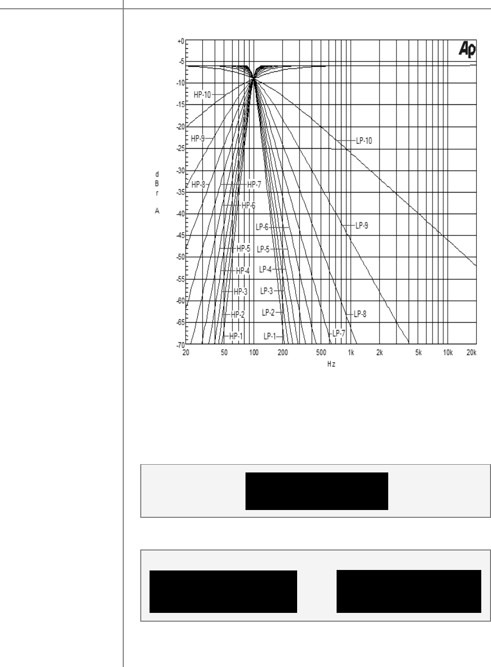
Fig 1 Left/Right channel frequency response. Output signal level at –6 dB
which is equivalent to 37.5 W into 8 Ohms or 70 W into 4 Ohms.
Left channel set to BUTT low-pass filter with FL set to 100 Hz and LO set from
1 to 10.
Right channel set to BUTT high-pass filter with FH set to 100 Hz and HO set
from 1 to 10.
EDIT Menu L: BUTT EDIT
R: BUTT EDIT
EDIT Left Channel Screen
L: LO HO FL-Hz FH-Hz
LP 10 -- 100 -----
R: LO HO FL-Hz FH-Hz
HP -- 10 ----- 100
EDIT Right Channel Screen
EDIT menu setup for
Fig. 1 measurements
L/R channel setup for
LP-1 and HP-1 curves
Measurement
Sample 1
Crossover Package M/S-2150 X
43Tact Audio
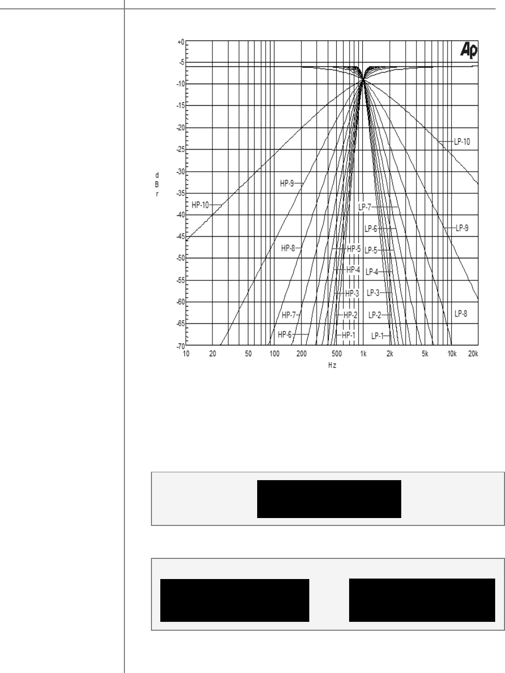
Fig 2 Left/Right channel frequency response. Output signal level at –6 dB
which is equivalent to 37.5 W into 8 Ohms or 70 W into 4 Ohms.
Left channel set to BUTT low-pass filter with FL set to 1000 Hz and LO set
from 1 to 10.
Right channel set to BUTT high-pass filter with FH set to 1000 Hz and HO set
from 1 to 10.
Measurement
Sample 2
EDIT Menu L: BUTT EDIT
R: BUTT EDIT
EDIT Left Channel Screen
L: LO HO FL-Hz FH-Hz
LP 5 -- 1000 -----
R: LO HO FL-Hz FH-Hz
HP -- 5 ----- 1000
EDIT Right Channel Screen
EDIT menu setup for
Fig. 2 measurements
L/R channel setup for
LP-5 and HP-5 curves
Crossover Package M/S-2150 X
CAUTIONCAUTION
44 Tact Audio
-70
+0
-65
-60
-55
-50
-45
-40
-35
-30
-25
-20
-15
-10
-5
d
B
r
6
500
10
20
50
100
200
Hz
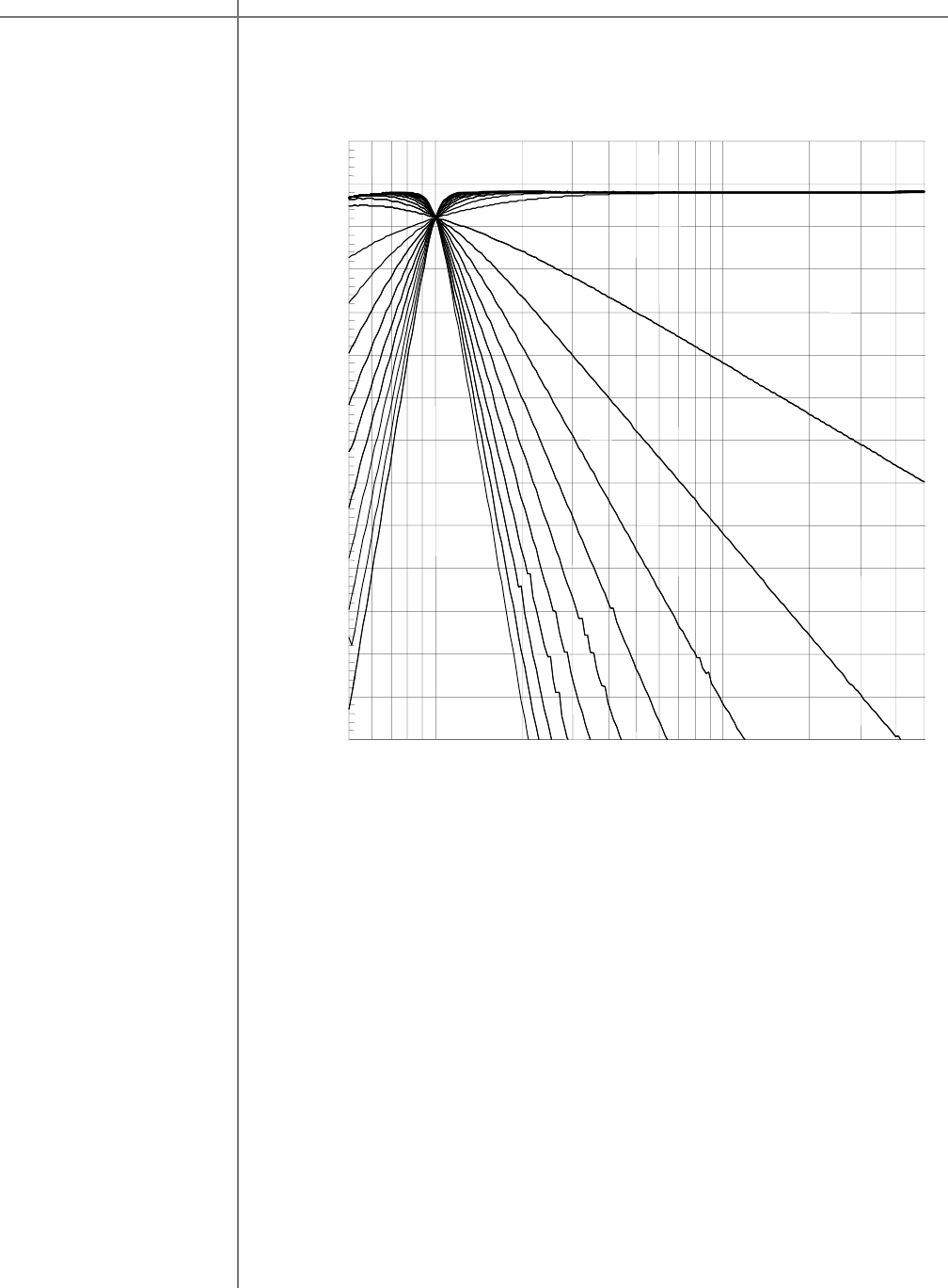
Fig 3 Low-pass and High-pass crossover filters with cutoff frequency of 10 Hz
and filter order from 1 to 10. Output signal level at –6 dB equivalent to 37.5 W
into 8 Ohms or 70 W into 4 Ohms.
Measurement
Sample 3
Crossover Package M/S-2150 X

45Tact Audio
-70
+0
-65
-60
-55
-50
-45
-40
-35
-30
-25
-20
-15
-10
-5
d
B
r
A
20
20k
50
100
200
500
1k
2k
5k
10k
Hz
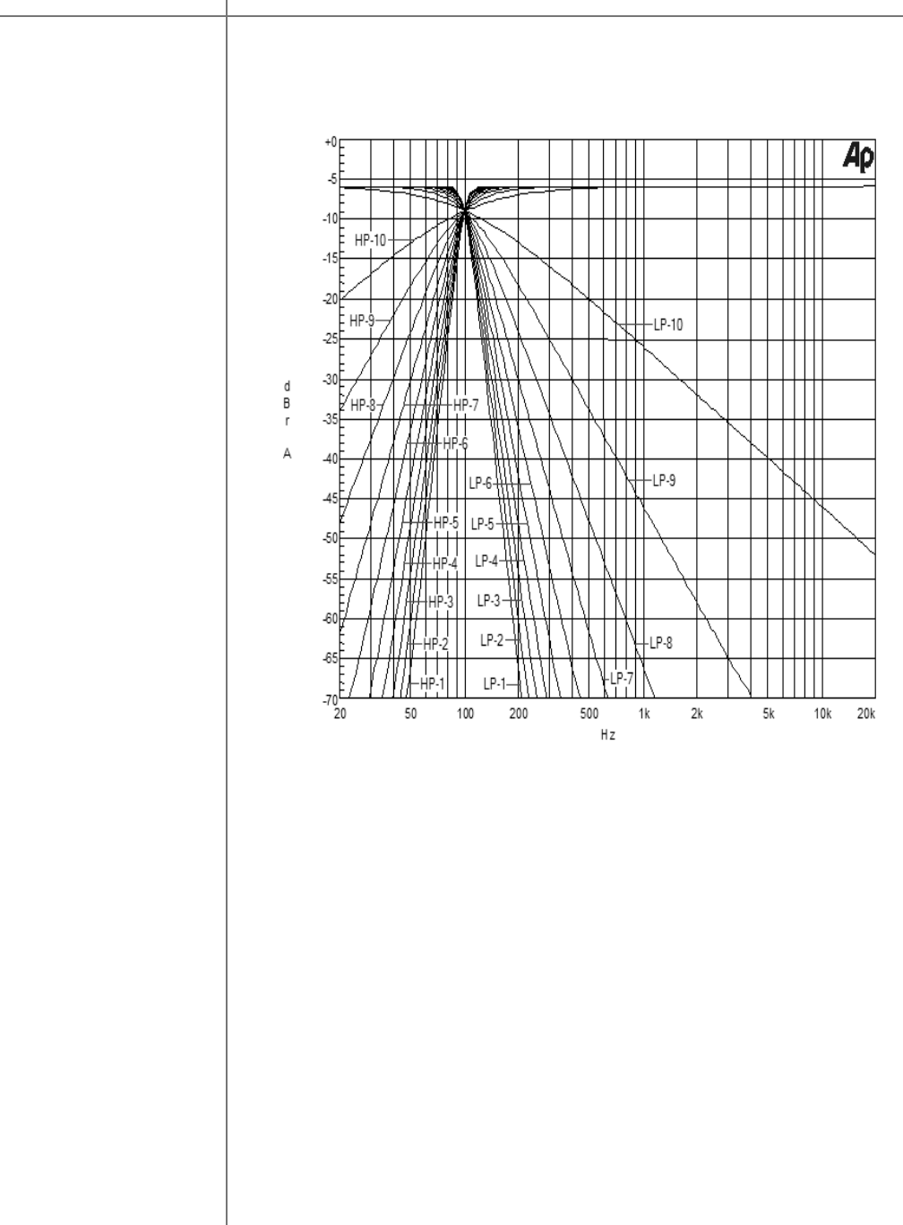
Fig 4 Low-pass and High-pass crossover filters with cutoff frequency of 100
Hz and filter order from 1 to 10. Output signal level at –6 dB equivalent to 37.5
W into 8 Ohms or 70 W into 4 Ohms.
Measurement
Sample 4
Crossover Package M/S-2150 X
CAUTIONCAUTION
46 Tact Audio
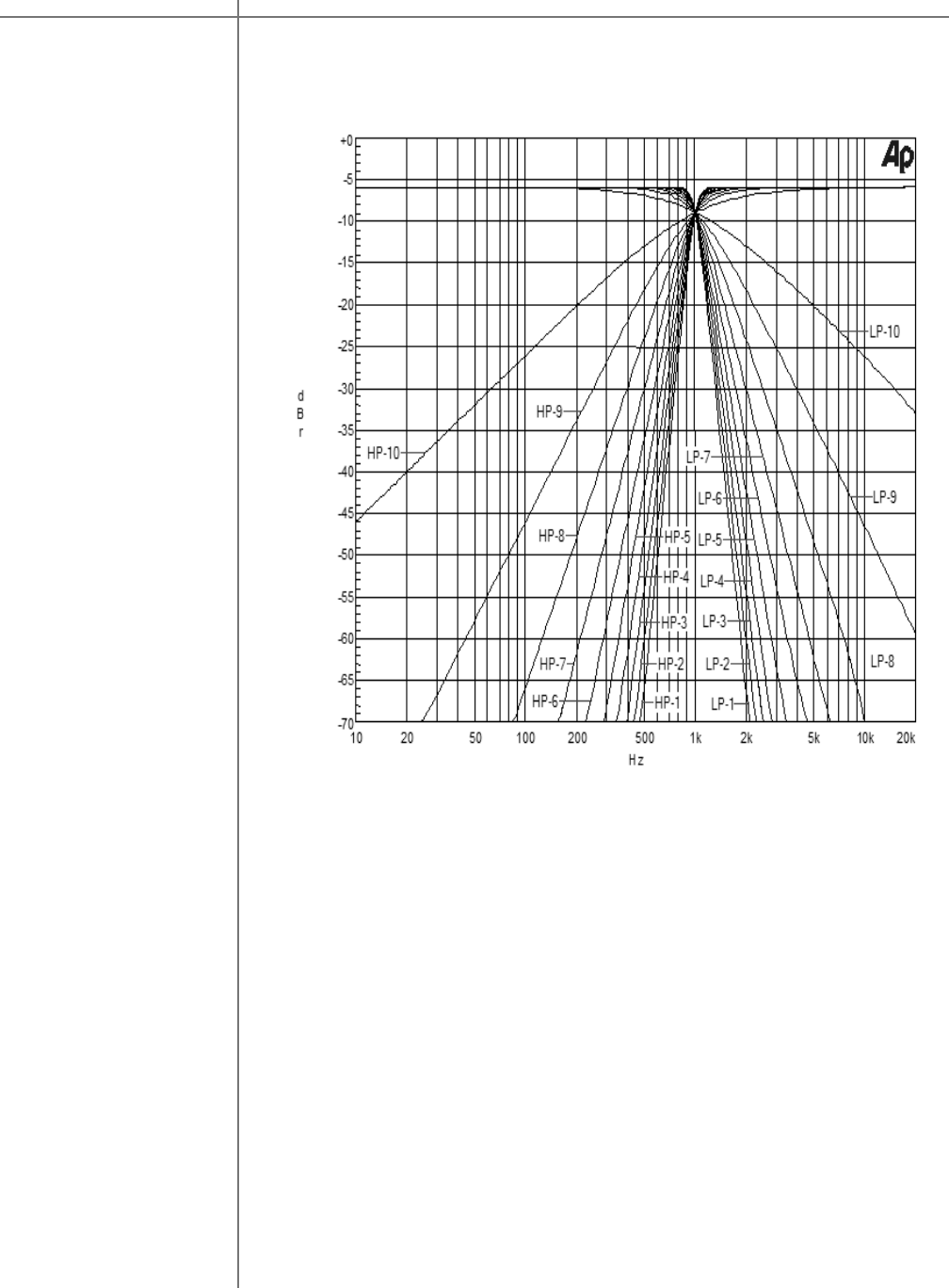
Fig 5 Low-pass and High-pass crossover filters with cutoff frequency of 1000
Hz and filter order from 1 to 10. Output signal level at –6 dB equivalent to 37.5
W into 8 Ohms or 70 W into 4 Ohms.
Measurement
Sample 5
Crossover Package M/S-2150 X
47Tact Audio
-70
+0
-65
-60
-55
-50
-45
-40
-35
-30
-25
-20
-15
-10
-5
d
B
r
100
20k
200
500
1k
2k
5k
10k
Hz
Fig 6 Low-pass and High-pass crossover filters with cutoff frequency of 10
KHz and filter order from 1 to 10. Output signal level at –6 dB equivalent to
37.5 W into 8 Ohms or 70 W into 4 Ohms.
Measurement
Sample 6
Crossover Package M/S-2150 X

CAUTIONCAUTION
48 Tact Audio
Subwoofer COR Application
Most high-end stereo configurations consist of two main loudspeakers covering
frequencies form fc up to 20,000 Hz, and two subwoofers covering bottom end of
the spectrum below fc. In most applications fc is set to around 100 Hz but it is not
unusual for fc to extend all the way to around 300 Hz. Properly integrating a
system like this one can be quite challenging. When subwoofers are properly
integrated with the main speakers it should be seamless and it should not be
noticeable that the sound is coming from the subwoofers. M/S-2150 X crossover
filter design package combined with level balancing and delay time feature can
greatly help to achieve this goal.
To power a system with two main channels and two subwoofers you will need two
M/S-2150 X amplifiers. There are two ways of connecting the amplifiers to the
speaker system:
1. One amplifier driving both subwoofers and another amplifier driving both
main channels. This configuration is referred to as horizontal bi-
amplification.
2. One amplifier driving left main channel loudspeaker and left subwoofer, and
another amplifier driving right main channel loudspeaker and right
subwoofer. This configuration is referred to as vertical bi-amplification.
Horizontal Bi-Amplification
In this configuration M/S-2150 X amplifier labeled as Amp#1 is connected to the
main left and right loudspeaker and M/S-2150 X amplifier labeled as Amp#2 is
connected to the left and right subwoofer. Connection diagram is shown on pages
15.
Note that digital source (usually processor or transport output) is connected to
Amp#1 coax/SPIDF digital input and Amp#1 digital output is connected to Amp#2
coax digital input. In this way both amplifiers get the same Left and Right channel
audio signal.
Example 1
Crossover Package M/S-2150 X
49Tact Audio
To make sure that both amplifiers will process Left and Right channel check
Amp#1 and Amp#2 InOut menu options. They should be set as follows:
OUTPUT: L R
SOURCE: L R *
OUTPUT: L R
SOURCE: L R *
Amp#1 InOut menu
Also make sure that initially for both amplifiers DELAY and LEVEL menu options
are set to as follows:
LEFT RIGHT
0.00 0.00 msec
LEFT RIGHT
0.0 0.0 dB
The next step is crossover filter selection for both subwoofers and main channels.
The crossover filter selection consists of setting subwoofer low-pass filter cutoff
frequency and filter order (filter slope), and of setting main channel high-pass cutoff
frequency and filter order (filter slope). Your loudspeaker manufacturer usually
recommends these parameters. In this example we assume that crossover
frequency is 100 Hz and the filter order is something we want to experiment with.
Each M/S 2150 X amplifier supports up to 9 crossover presets. Here we program
preset 1 (CRO- 1) with 10-th order filter as shown bellow.
L: LO HO FL-Hz FH-Hz
HP -- 10 ----- 100
R: LO HO FL-Hz FH-Hz
HP -- 10 ----- 100
R: LO HO FL-Hz FH-Hz
LP 10 -- 100 -----
L: LO HO FL-Hz FH-Hz
LP 10 -- 100 -----
Amp#2 InOut menu
Amp#1 and Amp#2 DELAY menu Amp#1 and Amp#2 DELAY menu
Left channel Amp#2 EDIT menu Right channel Amp#2 EDIT menu
Left channel Amp#1 EDIT menu Right channel Amp#1 EDIT menu
Example 1
Crossover Package M/S-2150 X

CAUTIONCAUTION
50 Tact Audio
CRO preset 2 (CRO- 2) for both amplifier is the same as preset 1 except that
in preset 2 filter order for both Left and Right channel is set to 9. CRO preset
2 is shown in figure below.
L: LO HO FL-Hz FH-Hz
HP -- 9 ----- 100
R: LO HO FL-Hz FH-Hz
HP -- 9 ----- 100
L: LO HO FL-Hz FH-Hz
LP 9 -- 100 ----- R: LO HO FL-Hz FH-Hz
LP 9 -- 100 -----
L: LO HO FL-Hz FH-Hz
HP -- 2 ----- 100
R: LO HO FL-Hz FH-Hz
HP -- 2 ----- 100
L: LO HO FL-Hz FH-Hz
LP 2 -- 100 -----
R: LO HO FL-Hz FH-Hz
LP 2 -- 100 -----
Repeat the same settings for the remaining presets with decreasing filter
order. CRO preset 10 should look like
To summarize:
•All the presets for Amp#1 are set to high-pass filter for both left and
right channel with cutoff frequency (HF-Hz) of 100 Hz and filter order
(HO) going from HO=10 for preset 1 (CRO –1) to HO=2 for preset 9
(CRO-9).
•All the presets for Amp#2 are set to low-pass filter for both left and
right channel with cutoff frequency (HF-Hz) of 100 Hz and filter order
(HO) going from LO=10 for preset 1 (CRO –1) to LO=2 for preset 9
(CRO-9).
Left channel Amp#1 EDIT menu
Left channel Amp#2 EDIT menu
Right channel Amp#1 EDIT menu
Right channel Amp#2 EDIT menu
Left channel Amp#1 EDIT menu Right channel Amp#1 EDIT menu
Left channel Amp#2 EDIT menu Right channel Amp#2 EDIT menu
Example 1
Crossover Package M/S-2150 X
51Tact Audio
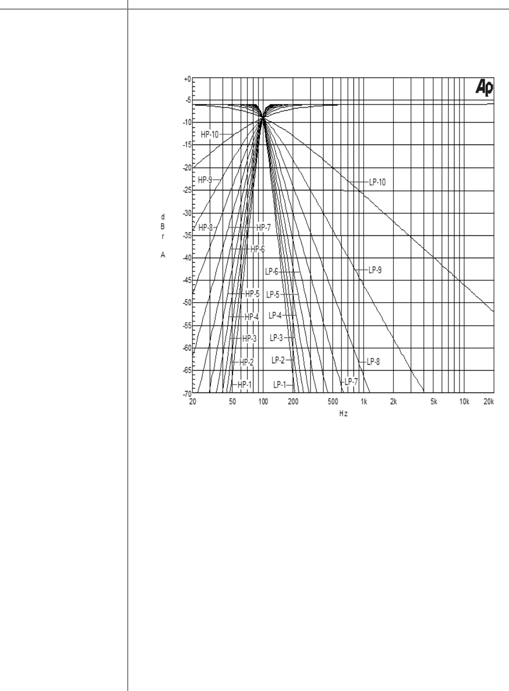
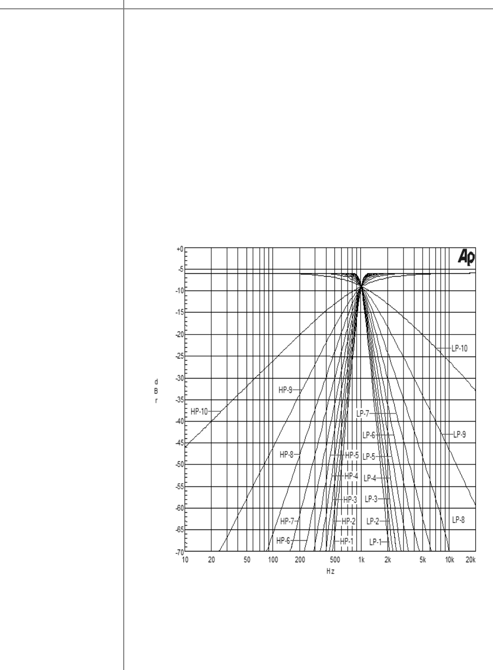
Fig. 7 Amp#1 and Amp#2 Left/Right channel frequency response. Output
signal level at –6 dB which is equivalent to 37.5 W into 8 Ohms or 70 W into
4 Ohms.
LP-2, LP-3, …,LP-10 represent Amp#2 Left/Right channel frequency
response with LP-2 corresponding to CRO preset 1 (CRO –1 ) , LP-3
corresponding to CRO preset 2 (CRO –2) and the last filter LP-10
corresponds to CRO preset 9 (CRO-9).
HP-2, HP-3, …,HP-10 represent Amp#1 Left/Right channel frequency
response with HP-2 corresponding to CRO preset 1 (CRO –1 ) , HP-3
corresponding to CRO preset 2 (CRO –2) and the last filter HP-10
corresponds to CRO preset 9 (CRO-9).
Example 1
Crossover Package M/S-2150 X
CAUTIONCAUTION
52 Tact Audio
Vertical bi-amplification
In this configuration M/S-2150 X amplifier labeled Amp#1 is connected to the main
left and subwoofer left channel. Left channel of Amp#1 is connected to the left
subwoofer and Amp#1 right channel is connected to the left main loudspeaker. M/
S-2150 X amplifier labeled Amp#2 is connected to the main right and subwoofer
right channels. Left channel of Amp#2 is connected to the right subwoofer and
right channel of Amp#2 is connected to the right main loudspeaker. Connection
diagrams are shown on pages 16.
Note that digital source (usually processor or transport output) is connected to
Amp#1 coax/SPDIF digital input and Amp#1 digital output is connected to Amp#2
coax digital output. In this way both amplifiers get the same Left and Right
channel audio signal. In this configuration Amp#1 is set to process only left
channel audio signal and Amp#2 is set to process only right channel audio signal.
Amp#1 and Amp#2 InOut menus should be set as follows:
Initially DELAY and LEVEL menu options for both amplifiers should be set to 0.00
msec and 0.0 dB respectively.
The next step is crossover filter selection for both subwoofers and main channels.
The crossover filter selection consists of setting subwoofer low-pass filter cutoff
frequency and filter order (filter slope), and of setting main channel high-pass cutoff
frequency and filter order (filter slope). Your loudspeaker manufacturer usually
recommends these parameters. In this example we assume that crossover
frequency is 100 Hz and the filter order is something we want to experiment with.
Each M/S-2150 X amplifier supports up to 9 crossover presets. Here we program
preset 1 (CRO- 1) as shown on the next page.
OUTPUT: L R
SOURCE: L L *
OUTPUT: L R
SOURCE: R R *
Example 2
Amp#1 InOut menu Amp#2 InOut menu
Crossover Package M/S-2150 X
53Tact Audio
L: LO HO FL-Hz FH-Hz
LP 10 -- 100 -----
R: LO HO FL-Hz FH-Hz
HP -- 10 ----- 100
L: LO HO FL-Hz FH-Hz
LP 10 -- 100 -----
R: LO HO FL-Hz FH-Hz
HP -- 10 ----- 100
L: LO HO FL-Hz FH-Hz
LP 9 -- 100 -----
R: LO HO FL-Hz FH-Hz
HP -- 9 ----- 100
L: LO HO FL-Hz FH-Hz
LP 9 -- 100 -----
R: LO HO FL-Hz FH-Hz
HP -- 9 ----- 100
CRO preset 2 (CRO- 2) for both amplifier is the same as preset 1 except that
in preset 2 filter order for both Left and Right channel is set to 9. CRO preset
2 is shown in the figure below.
Repeat the same settings for the remaining presets with decreasing filter
order. CRO preset 10 is shown in the figure bellow.
L: LO HO FL-Hz FH-Hz
LP 1 -- 100 -----
L: LO HO FL-Hz FH-Hz
LP 1 -- 100 -----
R: LO HO FL-Hz FH-Hz
HP -- 1 ----- 100
R: LO HO FL-Hz FH-Hz
HP -- 1 ----- 100
Left channel Amp#1 EDIT menu Right channel Amp#1 EDIT menu
Left channel Amp#2 EDIT menu Right channel Amp#2 EDIT menu
Left channel Amp#1 EDIT menu Right channel Amp#1 EDIT menu
Left channel Amp#2 EDIT menu Right channel Amp#2 EDIT menu
Example 2
Crossover Package M/S-2150 X

CAUTIONCAUTION
54 Tact Audio
To summarize:
•All presets for Amp#1 are set to low-pass filter for left channel and to
high-pass for right channel. Left channel cutoff frequency (LF-Hz) is
set to 100 Hz and right channel cutoff frequency (HF-Hz) is set to 100
Hz.
•Amp#2 CRO presets are identical to Amp#1 CRO presets.
NOTE: After any parameter CRO parameter in changed you must click on
SEND option to send that parameter to selected amplifier.
NOTE: In this configuration Amp#1 will process left audio channel only.
Amp#1 left output will output low-pass filtered left audio channel and Amp#1
right output will output high-pass filtered left audio channel. Amp#2 will
process right audio channel only. Amp#2 left output will output low-pass
filtered right audio channel and Amp#2 right output will output high-pass
filtered right audio channel.
After all setups are configured Amp#1 and Amp#2 will produce left and right
output with the frequency response as shown in Fig 7. Note that these curve
represent real measurements and they are not result of computer simulation.
Crossover Package M/S-2150 X
55Tact Audio
Fig 8 Amp#1 and Amp#2 Left/Right channel frequency response. Output
signal level at –6 dB which is equivalent to 40 W into 8 Ohms or 80 W into 4
Ohms.
LP-2, LP-3, …,LP-10 represent Amp#1 and Amp#2 Left channel frequency
response.
HP-2, HP-3, …,HP-10 represent Amp#1 and Amp#2 Right channel frequency
response
LP-2 corresponds to CRO preset 1 (CRO –1 ) , LP-3 corresponds to CRO
preset 2 (CRO –2) and the last filter LP-10 corresponds to CRO preset 9
(CRO-9).
HP-2 corresponds to CRO preset 1 (CRO –1 ) , HP-3 corresponds to CRO
preset 2 (CRO –2) and the last filter HP-10 corresponds to CRO preset 9
(CRO-9).
Example 2
Crossover Package M/S-2150 X
CAUTIONCAUTION
56 Tact Audio
Crossover Package M/S-2150 X
Two-Way Loudspeaker System
There are many advantages to using bi-amplification instead of the standard
configuration, where one power amplifier is used to drive one loudspeaker with two
or more drivers along with passive crossover networks. In the world of high-end
audio in the last few years there has been constant increase in demand for
sophisticated DSP based bi-amplification solution. To make bi-amplification
available to Tact users M/S-2150 X incorporates crossover package that can place
crossover frequency anywhere from 10 to 20,000 Hz with frequency resolution of 1
Hz.
In a two-way loudspeaker system, the base and the midrange signals go to the
woofer and signals above the crossover frequency go to tweeter. In a system like
this one it is recommended to eliminate passive crossover components and
connect the woofer and the tweeter driver to separate channel of amplification with
digital crossover filters embedded into each amplifier. In this way each driver is
connected directly to the respective power source. There is no component
between the power source and the driver that could in any way interfere with the
power transfer from the amplifier to the driver. This approach eliminates many
abnormalities introduced by passive crossover and one amplifier per channel
design.
The driver manufacturers usually recommend crossover frequency. In this example
we assume that the crossover frequency is set to 1000 Hz.
Like in the subwoofer case there are two ways of bi-amplifying a two-way
loudspeaker system: horizontal and vertical.
Horizontal bi-amplification
In horizontal bi-amplification one amplifier is used to drive both left and right
channel woofers, and another amplifier is used to drive both left and right channel
tweeter. One M/S-2150 X labeled Amp#1 is used to drive both woofers and another
M/S-2150 X labeled Amp#2 is used to drive both tweeters. System connection
diagrams are shown on pages 15.
Note that digital source (usually processor or transport output) is connected to
Amp#1 coax/SPIDF digital input and Amp#1 digital output is connected to Amp#2
Example 3
CAUTIONCAUTION
58 Tact Audio
Crossover Package M/S-2150 X
Example 3 To summarize:
•All the presets for Amp#1 are set to low-pass filter for both left and right
channel with cutoff frequency (LF-Hz) of 1000 Hz and filter order (LO)
going from LO=10 for preset 1 (CRO –1) to LO=1 for preset 9 (CRO-9).
•All the presets for Amp#2 are set to high-pass filter for both left and right
channel with cutoff frequency (HF-Hz) of 1000 Hz and filter order (HO)
going from HO=10 for preset 1 (CRO –1) to HO=1 for preset 9 (CRO-9).
After all setups are configured Amp#1 and Amp#2 will produce left and right output
with the frequency response as shown in Fig 9. Note that these curve represent
real measurements and they are not result of computer simulation.

59Tact Audio
Crossover Package M/S-2150 X
TacT Audio, Inc.
201 Gates Road Unit G, Little Ferry – New Jersey 07643, USA
Phone: +1 201 440 9300 – Fax: +1 201 440 5580 – Email: info@tactaudio.com
www.tactaudio.com
