Tactical Electronics SX450G UHF TRANSCEIVER User Manual
Tactical Electronics Corporation UHF TRANSCEIVER Users Manual
USERS MANUAL
1892 1344 - SX450G Transceiver Operator Guide v1.2 / Dec 2006 1
SX450 G TRANSCEIVER
OPERATING INSTRUCTIONS
These operating instructions are intended to provide the user with sufficient information to
install and operate the unit correctly.
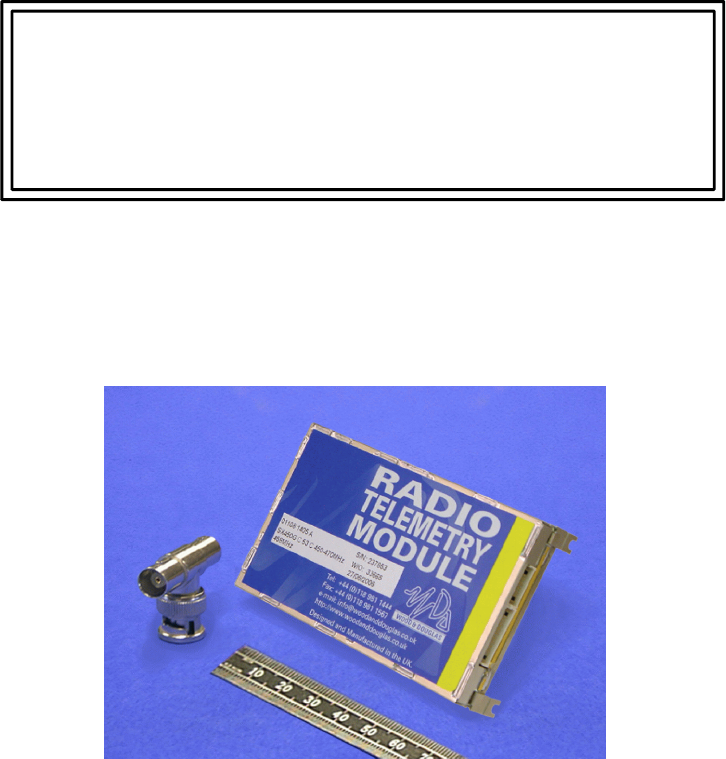
The SX450 G is a high-performance synthesized UHF transceiver for
use in radio telemetry applications. The transceiver provides a maximum power output of
500mW and is designed to meet European standards EN 300 220, EN300 086 and
EN300 389. The unit also complies with USA FCC and Industry Canada standards.
Two versions are available, the SX450 GA and the SX450 GC. They differ only in
connections, and are functionally identical.
Tactical Electronics Corporation
13 December 2006
21892 1344 - SX450G Transceiver Operator Guide v1.2 / Dec 2006
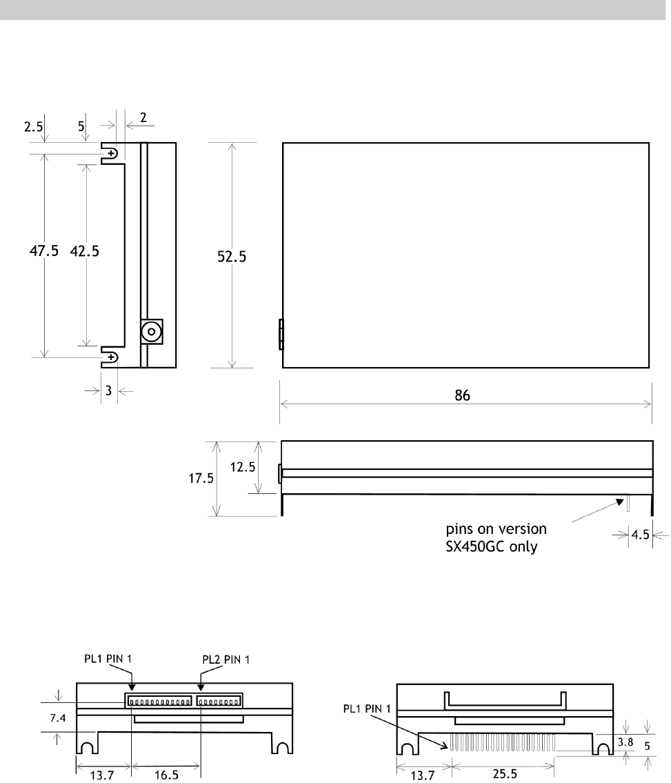
Figure 1 SX450 G fixing detail
DIMENSIONS AND FIXING
The SX450 G is intended to fit easily and with minimum space requirements into the
user's own equipment housing.
Figure 2 - SX450 GA connectors Figure 3 - SX450 GC connector
1892 1344 - SX450G Transceiver Operator Guide v1.2 / Dec 2006 3
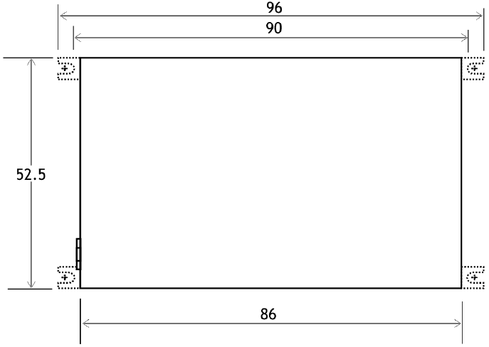
The four corner tabs of the enclosure can be folded out to provide alternative mounting of
the unit, with fixing centres of 93.00 x 47.5mm using four M2 screws.
Figure 4 - Alternative mounting dimensions

41892 1344 - SX450G Transceiver Operator Guide v1.2 / Dec 2006
CONNECTIONS
The radio antenna connects via an MMCX 50O socket.
All other connections to the SX450 GA transceiver are made via a 12-way connector PL1
and an 8-way connector PL2. These are single-in-line plugs for use with the free-issued
connectors with flying leads.
All other connections to the SX450 GC transceiver are made via a 21-way SIL PCB
connector, PL1.
SX450
GA SX450
GC NAME FUNCTION REMARKS
PL1-1 PL1-1 0V 0 volts common ground
PL1-2 PL1-2 STBY standby input LOW (<+0.6V) = transceiver enabled
HIGH (>+2.0V) = standby mode
(internal pull-up, 40K to +4V max)
PL1-3 PL1-3 HI/LO TX RF power select
input >+2.0V = high power, <+0.8V = low power
(internal pull-down, 10K to 0V)
PL1-4 PL1-4 +Vin positive supply input +5.5 to +9.0 V input (-ve earth)
PL1-5 PL1-5 TXE transmit enable input HIGH (>+2.0V) = receiver enabled
LOW (<+0.8V) = transmitter enabled
(internal pull-up, 100K to +5V)
PL1-6 PL1-6 TXD/MS TXD - serial data
input
MS - mode select,
ie channel
selection by
serial or
parallel data
input
Serial data input = single 8-bit RS232 format
control word,
ie logic 1 = -V, logic 0 = +V (Maximum voltage
level is +12V; inverted TTL acceptable).
Mode selected depends on the logic state:
HIGH > 1ms (>+2.0V) = parallel data input
LOW (<+0.8V) = serial data input
(internal pull-up, 50K to +3V)
PL1-7 PL1-7 CS0/DT CS0 - channel
select input
(LSB)
DT - synthesizer
serial data
input*
Channel select inputs use inverted 5V logic
levels;
HIGH (>+2.0V) = logic 0, LOW (<+0.8V) = logic 1
CS0 to CS5 are used for channel selection by 6-
bit parallel data
(Internal pull-ups 100K to +5V)
(* DT/CK/EN inputs are used for direct control of
the synthesizer, this is a separate version of the
SX450.)
PL1-8 PL1-8 CS1/CK CS1 - channel
select input
CK - synthesizer
programme
clock *
PL1-9 PL1-9 CS2/EN CS2 - channel
select input
EN - synthesizer
enable strobe
input*
PL1-10 PL1-10 CS3 channel select input
PL1-11 PL1-11 CS4 channel select input

1892 1344 - SX450G Transceiver Operator Guide v1.2 / Dec 2006 5
PL1-12 PL1-12 CS5 channel select input
(MSB)
PL1-13 -not connected -
PL2-1 PL1-14 RF DET TX RF present flag
output HIGH (+5V, internal 10K pull-up) = TX RF
present
LOW (0V) = no TX RF
NOTE: only available when high TX RF power is
selected
PL2-2 PL1-15 AF O/P receiver audio output 600mV p.p. nom. into 10K; AC-coupled; Rout =
2K3.
PL2-3 PL1-16 SQO squelch flag output NPN open collector via 470O; ON = no signal,
OFF = signal present.
(NOTE: OFF when transceiver in standby mode)
PL2-4 PL1-17 OOL out-of-lock output NPN open collector via 470O; ON = out of lock
(NOTE: OFF when transceiver in standby mode)
PL2-5 PL1-18 DMOD digital modulation
input ** +3V to +12V square wave, DC-coupled
** DMOD and AMOD may not be used
simultaneously. Leave unused input
unconnected.
PL2-6 PL1-19 AMOD analog modulation
input ** 750mV p-p., AC-coupled (pre-settable 200mV to
3V p-p.)
** DMOD and AMOD may not be used
simultaneously. Leave unused input
unconnected.
PL2-7 PL1-20 RSSI 'S' meter output 0V to +3V output, rising with received signal level
(typ. 50dB range)
PL2-8 PL1-21 SQOR squelch override input HIGH (>+2.0V) enables AF O/P regardless of
squelch state (RX only)
LOW (+0.8V or o/c) = normal operation
(internal pull-down, 70K to 0V)

61892 1344 - SX450G Transceiver Operator Guide v1.2 / Dec 2006
OVERVIEW OF FREQUENCIES AND PROGRAMMING
Each radio is built to order to cover a band (the switching bandwidth) of 15 or 20MHz
within the range 400 - 490MHz. Available bands are 400-415, 415-430, 430-450, 450-
470, and 470-490MHz. Each radio is also manufactured to work with a particular channel
width of 12.5kHz, 20kHz or 25kHz. These are fixed parameters, and cannot be changed
by the user.
Within the switching bandwidth, the unit can operate on any frequency (provided it is a
whole multiple of the comparison frequency - see page 9), and up to 256 frequencies can
be stored as numbered channels 0 to 255.
There can also be an offset between transmit and receive frequencies, which is the same
for all channels. You can set this offset, but both transmit and receive frequencies must
remain within the switching bandwidth, fixed at manufacture.
During operation, a channel can be selected at any time either using logic lines or a serial
data input. Logic lines can only select channels 0-63, serial commands can select any
channel.
Before the unit leaves the factory, each of 256 channels is allocated to a frequency, but
you can reprogram them if you wish. To do this, you need to read the existing data from
the unit, edit it using a special program supplied by Wood & Douglas (SXWIN.EXE),
which runs on a PC under Windows, then write the data back to the unit.
You can program the unit in one of two ways:
v256-channel mode: All 256 channels 0-255 can be programmed, but as a
block by entering a starting frequency and a step size, so that they contain
uniformly spaced frequencies.
v80-channel mode: Each of channels 0-79 can be individually programmed
with any frequency, but the remaining channels 80-255 are not available for
use.
One channel is then nominated as the operational channel.
1892 1344 - SX450G Transceiver Operator Guide v1.2 / Dec 2006 7
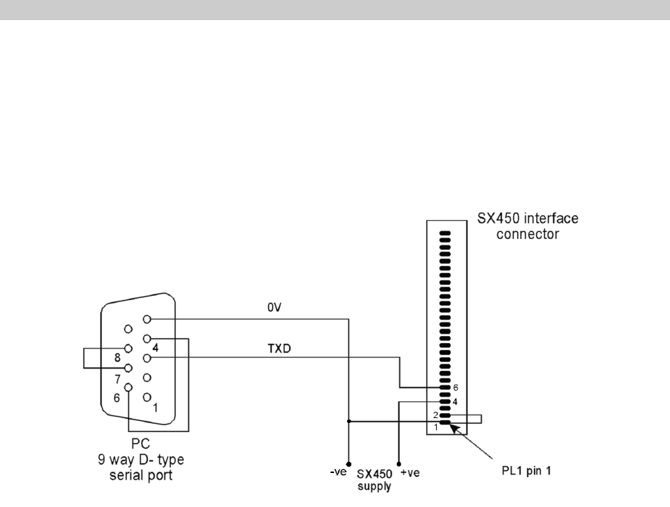
CONNECTING THE UNIT TO A PC FOR PROGRAMMING
In order to program the unit, the unit and a PC (IBM-compatible personal computer) must
communicate via an asynchronous RS232 serial link. The unit also requires a power
supply.
The adaptor of Figure 3 provides these connections.
Figure 5 - Adaptor to connect a PC to an SX450 G
The power supply should source between 4.5V and 16V DC at approximately 60mA.
81892 1344 - SX450G Transceiver Operator Guide v1.2 / Dec 2006
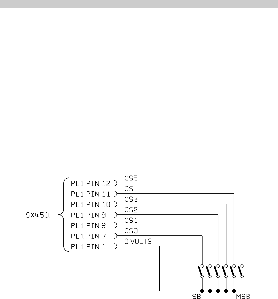
Figure 6 - Parallel channel selection
CHANNEL SELECTION DURING OPERATION
There are three ways to select a channel during operation:
vIn hardware, using six logic lines to select channels 0-64
vUsing the SXWIN.EXE software and a serial connection from a PC to the
unit
vBy sending a short serial data message to the unit from your own equipment.
Parallel Channel Selection
vPL1 pin 6 must be logic high (>2.0V) or high-impedance (e.g. no connection)
to select parallel channel selection. This can be done at any time.
vOnly channels 0 - 63 are available in this mode
The six channel select inputs are an inverse binary representation of the channel number,
that is, switch ON = input LOW = logic 1. If no connections are made, the unit therefore
defaults to channel 0.
Changes are implemented immediately.
The logic levels are : LOW < 0.8V
HIGH > 2V or floating
1892 1344 - SX450G Transceiver Operator Guide v1.2 / Dec 2006 9
Serial Channel Selection
vPL1 pin 6 must be logic low (<0.8V) to select serial channel selection. This
can be done at any time.
vChannels 0 - 255 are available in this mode
When PL1 pin 6 is first taken low (or it is low at power-up), the unit operates on the
channel most recently selected in serial mode. This setting is remembered during unit
power off.
The channel can be changed by sending a serial channel number as an RS232 character
on PL1 pin 6. The SXWIN.EXE software has the ability to do this, or you can use your
own equipment. The protocol is:
9600 baud, RS232 levels, 1 start bit - 8 bit data - no parity - 1 stop bit
Single-byte, channel number in binary, LSB first (decimal 0 to 255)
As soon as the character is recognised as a valid RS232 character, the channel is
changed. No confirmation is required.

10 1892 1344 - SX450G Transceiver Operator Guide v1.2 / Dec 2006
RANGE INFORMATION
The following table gives an indication of the typical ranges to be expected between a
transmitter and receiver that have simple end-fed dipole antennas.
The following assumptions have been made in the calculations:
line-of-sight between antennas
0dB gain for the transmitter and receiver antennas
0dB loss for connectors and cables between the antenna and the radio connector
20dB fade and environmental margin
-100dBm received signal strength, allowing for digital and analog signals
Range versus TX power
Frequency (MHz) Power (mW) Power (dBm) Range (km)
458.5 1mW 00.5
458.5 10mW 10 1.7
458.5 100mW 20 5.3
458.5 500mW 27 11.9

1892 1344 - SX450G Transceiver Operator Guide v1.2 / Dec 2006 11
TECHNICAL SPECIFICATION
General
Frequency range 400-490MHz available. Specify 400-415, 415-430, 430-
450, 450-470 or 470-490MHz when ordering.
Switching bandwidth 15 or 20MHz depending on band ordered.
Frequency stability +2.6ppm over operating temperature
Channel switching delay 100ms maximum (over 20MHz switching bandwidth)
Channel selection 64 channels maximum using 6-bit parallel logic line input.
256 channel maximum sequential, 80 individually
programmed using serial data word.
Channel spacing 12.5kHz/20kHz/25kHz available
Modulation type F1D/F2D/F3D
Spurious emissions (conducted & radiated) In accordance with ENI/CEPT
Supply voltage 4.5 to16V DC negative earth
Supply current at 7.2V 60mA typical (receive), 400mA typical for 500mW output
(transmit)
Interface connections 21 pin SIL PCB connection (SX450 GC)
1 x 8 + 1 x 12 way 1.27mm pitch Molex plug with mating
connectors + 200mm leads (SX450 GA)
RF connection PC mounted socket
Operating temperature -30%C to +55%C
Storage temperature -30%C to +70%C
Size overall 85 x 55 x 12.7mm
Weight 81g
Type approvals -
complies with: EN300 220, EN300 389 (EMC), EN300 086, FCC Part 90
and Part 15

12 1892 1344 - SX450G Transceiver Operator Guide v1.2 / Dec 2006
Transmitter
RF output power into 50O 500mW (HI) (+0/-1.5dB) 5mW (LO)
TX/RX switching time <25ms
Modulation input
analogue
digital 750mV p-p, AC-coupled
+3 to +12V square wave DC-coupled
Frequency response 9Hz to 3kHz at -3dB (analog input)
(optional extended response to 6kHz for 9600 baud
GMSK)
Frequency deviation
25kHz channel spacing
20kHz channel spacing
12.5kHz channel spacing
+3.0kHz nominal (+4.0kHz max)
+2.3kHz nominal (+3.0kHz max)
+1.5kHz nominal (+2.0kHz max)
Adjacent channel power <200nW (-37dBm)
Facilities RF detect output (+5V = TX on) (HI power only)
Receiver
Sensitivity <-115dBm for 12dB SINAD (Measured with flat
audio response)
<-107dBm for 20dB SINAD (Measured with flat
audio response)
Image rejection >70dB
Intermodulation rejection >65dB
Blocking >84dB
Spurious rejection >70dB
Intermediate frequencies 45MHz and 455kHz
Adjacent channel rejection
12.5kHz channel spacing
20/25kHz channel spacing >60dB
>70dB
Recovered audio level 600mV p-p (+20%) into 10K
Squelch type Noise operated
Squelch output NPN open collector via 470O
ON = no signal, OFF = signal present
Facilities RSSI output (0 to +3V nominal from 2K2 source)
Squelch override input
STBY input Standby current 150uA typ for HI/LO input = 0V

Tactical Electronics Corporation
4000 Dow Road, Melbourne, Florida 32934
Tel: 321 253 0845 Fax: 321 253 6466
email: info@tacel.com
website: www.tacel.com
1892 1344 - SX450 G Transceiver Operator Guide v1.2 / Dec 2006 13