Tactical Electronics SX500 100m WATT UHF TRANSCEIVER User Manual TRANSCEIVER
Tactical Electronics Corporation 100m WATT UHF TRANSCEIVER TRANSCEIVER
MANUAL

SX500 TRANSCEIVER
OPERATING INSTRUCTIONS
These operating instructions are intended to provide the user with sufficient information to
install and operate the unit correctly.
The SX500 UHF transceiver is intended to fulfil numerous OEM narrow band UHF
applications by virtue of its highly flexible synthesized design approach, miniature size and
cost-effective performance. The transceiver is used for telemetry links and provides
an RF output power of 100mW.
The unit complies with both FCC Part 90 and Industry Canada type acceptance requirements
as well as being approved to the EN 300 220 specification for use throughout Europe
and much of the world The module is also approved to the EMC specification ETS 300 683.

A label must be applied to the outside of the equipment containing the following details:
FCC
FCC ID : EFOSX500 Complies with FCC Parts 90 and 15
Frequency (MHz) Restrictions Equipment Marking
458.5000 Band Edge
458.5125 SRD SI 1993/1591-15-GB
458.5250 SRD SI 1993/1591-15-GB
458.5375 SRD SI 1993/1591-15-GB
458.5500 SRD SI 1993/1591-15-GB
458.5625 SRD SI 1993/1591-15-GB
458.5750 SRD SI 1993/1591-15-GB
458.5875 SRD SI 1993/1591-15-GB
458.6000 SRD SI 1993/1591-15-GB
458.6125 SRD SI 1993/1591-15-GB
458.6250 SRD SI 1993/1591-15-GB
458.6375 SRD SI 1993/1591-15-GB
458.6500 SRD SI 1993/1591-15-GB
458.6625 SRD SI 1993/1591-15-GB
458.6750 SRD SI 1993/1591-15-GB
458.6875 SRD SI 1993/1591-15-GB
458.7000 SRD SI 1993/1591-15-GB
458.7125 SRD SI 1993/1591-15-GB
458.7250 SRD SI 1993/1591-15-GB
458.7375 SRD SI 1993/1591-15-GB
458.7500 SRD SI 1993/1591-15-GB
458.7625 SRD SI 1993/1591-15-GB
458.7750 SRD SI 1993/1591-15-GB
458.7875 SRD SI 1993/1591-15-GB
458.8000 SRD SI 1993/1591-15-GB
458.8125 SRD SI 1993/1591-15-GB
458.8250 MPT1361 Only SRD SI 1993/1591-4-GB
458.8375 MPT1361 Only SRD SI 1993/1591-9-GB
458.8500 SRD SI 1993/1591-15-GB
458.8625 SRD SI 1993/1591-15-GB
458.8750 SRD SI 1993/1591-15-GB
458.8875 SRD SI 1993/1591-15-GB
458.9000 MPT1361 Only SRD SI 1993/1591-11-GB
458.9125 SRD SI 1993/1591-15-GB
458.9250 SRD SI 1993/1591-15-GB
458.9375 SRD SI 1993/1591-15-GB
458.9500 Band Edge
INSTALLATION
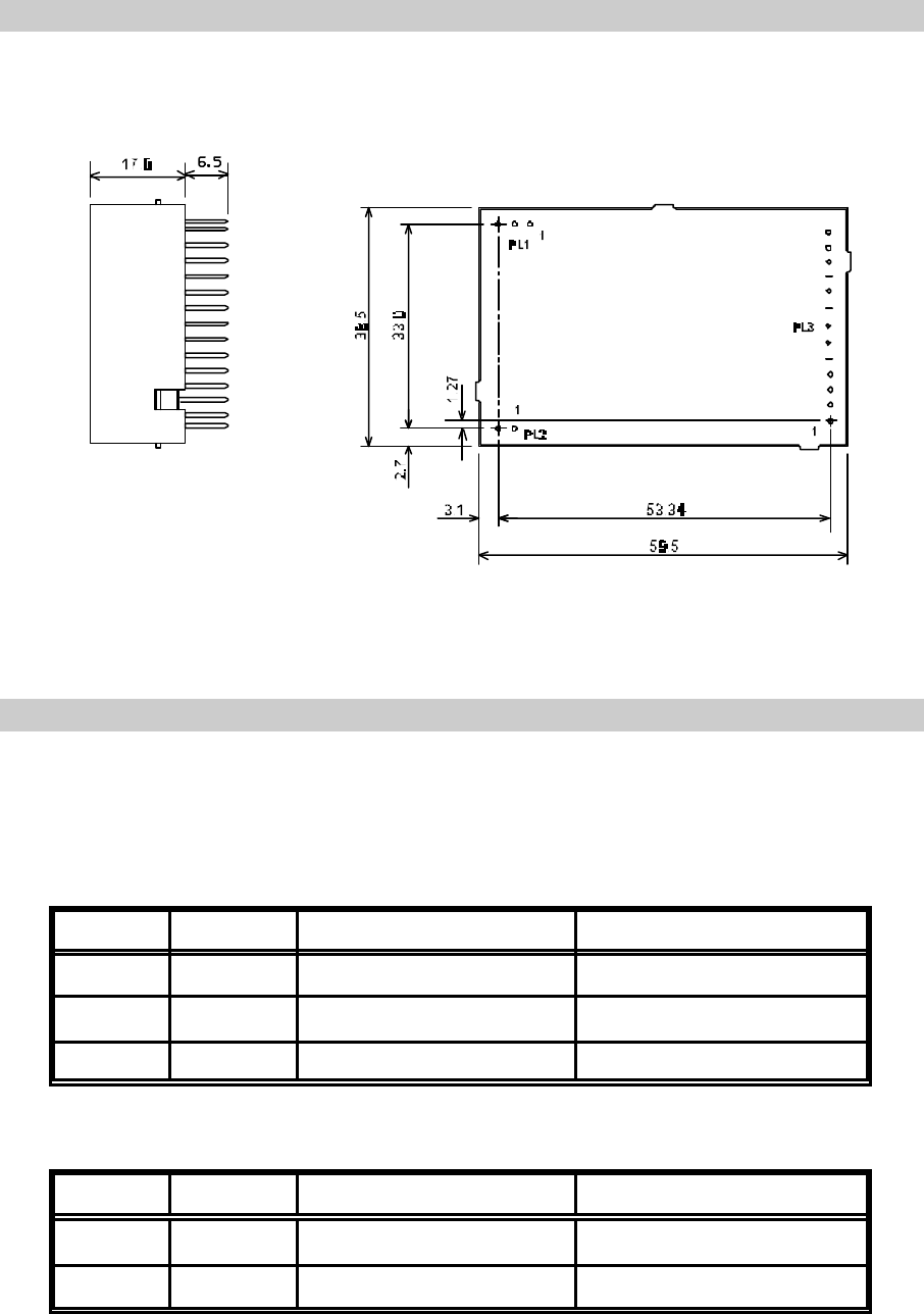
NOTES: Pin spacing on all connectors is 2.54mm (0.1")
All dimensions in millimetres
Figure 1 SX500 Outline Drawing
CONNECTION
Connection to the SX500 transceiver is via PL1, PL2 and PL3 which plug directly into the
user's own equipment. The location of these connectors is shown in Figure 1 and detailed
in the following tables.
PL1 PIN NAME FUNCTION REMARKS
10V 0 volts common ground
2RF O/P RF output 50 ohms output
30V 0 volts common ground
Table 2 PL1 Pin Connections
PL2 PIN NAME FUNCTION REMARKS
1+VRAW DC Supply Input 5.5 - 15 VDC input
20V 0 volts common ground
Table 3 PL2 Pin Connections
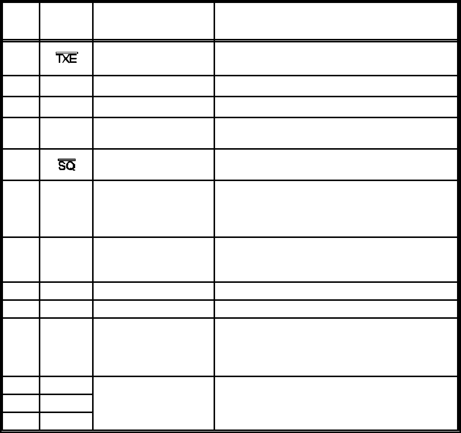
PL3
PIN NAME FUNCTION REMARKS
1Transmit Enable < 0.5V = Transmit ON
(internal 20kS pullup)
2DI Data Input Digital: DC coupled TTL compatible
3 AI Analog Input Analog : 750 mV p-p nominal
4RSSI Received Signal
Strength Indication RSSI: 0.5 - 2.0 V, 60dB dynamic range
(<33kS output impedance)
5Squelch Open drain to <0.4V with 10kS load.
Low = No Signal
6AF Audio Output 250mV p-p nominal
(~1kS output impedance)
Note inversion of audio from TX input to RX
output
7DATA
O/P Data output Open collector digital output
Note inversion of data from TX input to RX
output
8+VOUT + 5 volt supply output VOUT= 50mA maximum current drain
90V 0 volts common ground
10 RS232
I/P serial
programming
i/p
RS232 programming input
Note inverted TTL level data can also be used.
If not used, leave not connected, or connect to
ground.
11 RB1 parallel frequency
select internal pull-up to +5V, active low12 RB2
13 RB3
Table 3 PL3 Pin Connections
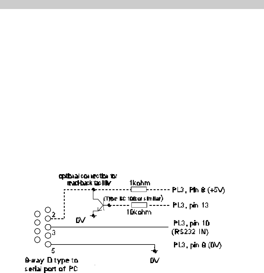
Figure 2 Programming Adaptor
FREQUENCY PROGRAMMING
An area of the PIC memory is re-programmable and allows up to 24 channels to be set to
random frequencies and 232 channels to be set to sequential frequencies. The first 8 of
the random frequencies can be accessed in parallel mode using the three programming
pins RB1, 2 and 3. To access the rest of the channels, the serial programming mode is
required. The channel change can be controlled through this serial input.
The Windows® based software supplied with the SX500 transceiver allows both a new
channel to be selected as well as the re-programming of the internal frequency information.
The software can be run on a PC with the serial port connected to PL3 of the SX500
transceiver via a suitable adaptor as shown in Figure 2. If the internal stored data is to be
accessed, the read-back function is desired, then PL3 pin 13 of the transceiver must be
connected to pin 2 of the PC serial port via a buffer circuit. A 1k pull-up resistor to +5V
must also be provided as shown.
Software Installation
The s/w is installed by following the normal procedures for installing windows based
software.
Insert CD or the first floppy disk and run the “setup.exe” program. Follow the on-screen
instructions and the s/w will be installed into the c:\program files\sx500 directory (WIN98)
or c:\programs\sx500 (WIN95) directories. A program icon will be placed in the s/w group
designated during the installation routine.
Running the Software
The s/w is accessed after installing by a single click on the SX500 icon. A screen page
as shown in the following figure will be displayed. All functions are accessed through this
screen.
The fields shown in colour can be accessed and modified. Those field shown in grey are
fixed by the hardware of the SX500 and cannot be changed by the user.
Data is accessed by moving through the fields using the mouse or the TAB key. Where
data can be modified, a short description of the data is shown at the bottom of the screen
as an aide-memoir.
There are 4 main areas of the screen plus the drop-down menu buttons at the top of the
screen. The default settings of the screen give the user access to the common data to be
modified through these four areas:
Random Channel Table This gives access to the first 24 channels which can
be set to any random frequency.
Sequential Channel Table This gives access to the 232 channels which can only
be sequential
Current Settings This sets up the program parameters
Unit Program Commands This area sets up the data transfer to and from the
SX500
Top Level Menu
File Load Load a pre-stored set of data.
A file list is displayed which can be selected and loaded by using the
mouse, highlighting and double clicking.
Save Save the current set of data
A set of directories are displayed. When in the correct directory, over-write
the default file name displayed and click or hot <ENTER>.
Print Print the current set of data.
The currently selected Windows default printer will be used.
Exit Exit the program.
View Internal EEPROM Contents
This displays in a separate window the contents of the units EEPROM. The data displayed
is for the functions and channels displayed on the main screen at that time. Data can be
hand-modified by moving highlighting the data and over-writing it. THIS SHOULD ONLY
BE CARRIED OUT WITH FULL KNOWLEDGE OF THE INTERNAL WORKING OF THE
SX500. Note that the type of data in each field is displayed at the bottom of the window.
While this window is displayed, no access is available to the main screen. The window
must be cleared down by clearing the “tick” in the View drop-down menu.
Unit Settings
PIC Code only displayed when the Readback function has been used to download the
contents of the EEPROM.
Current Settings Data
COM port Select the correct serial port for the connection to the SX500,
default COM1.
Intermediate Frequency The Intermediate Frequency is fixed by the hardware and
cannot be accessed
Fosc The oscillator frequency is fixed by the hardware and cannot
be accessed.
Comparison Freq. (Fc) The channel step size is fixed by the hardware at 12.5 kHz.
For 25kHz or other channel spacings, set the Table Step size
accordingly.
Minimum Frequency The minimum frequency is used by the software as a base-
line for all other frequency information. This frequency is
determined by the physical build of the unit and how it has
been aligned. The s/w will not allow a frequency below this
minimum to be selected. This frequency is stored in the non-
volatile EEPROM in the unit.
Maximum Frequency The maximum frequency that the unit can work on is
determined by the physical build of the unit and the alignment
of the unit. If a frequency outside the alignment band is
selected then the operation of the SX500 will no longer be to
the stated specification. The maximum switching frequency
over which the unit will operate is 5MHz. The software uses
this 5MHz limit to calculate the maximum frequency from the
minimum set and uses this for the selectable frequencies in
the drop-down list displayed when selecting frequencies.
This 5 MHZ band can be different for the transmit and receive
frequencies.
Receiver Offset The normal operation of the SX500 is with the transmit and
receive frequency the same. If an offset is required, a fixed
offset can be made between the frequencies by double-
clicking to bring up a selection of offsets. If a frequency
outside the alignment band is selected then the operation of
the SX500 will no longer be to the stated specification
Max. Channel Number This number will determine how many sequential channels are
programmed into the table.
Serial/Parallel To ensure the correct operation of the unit after programming
set this flag accordingly. After programming the unit the serial
or parallel mode will be set according to this selection.
Serial Channel No. To change channel select a new channel number by right-
clicking to bring up a list or double-clicking to select the field
to modify.
Random Channel Table
The first 24 channels of the SX500 can store randomly selected channels, which are non-
sequential or separated by a common gap. To change an existing frequency, double-click
the particular channel. Either type in a new frequency or select from a displayed list of
allowed frequencies.
Sequential Channel Table
To program these frequencies, ensure that the Max. Channel Number field in the “Current
Settings” is set correctly. Under the “Sequential Channel Table” area enter the start
frequency and the Table Step size to set the frequencies in the table.

Unit Programming Commands
To access these 4 functions, double-click on the text or highlight and press ENTER. When
accessed, the relevant data areas on the other three screen areas are highlighted to show
which data is being transferred.
Set parallel ch. mode Changes the SX500 from serial channel selection mode
to/from parallel.
Read from the unit Download the data from the SX500, assuming that the correct
interface lead has been made.
Program unit SeSend all the data displayed on the screen to the unit.
Program serial channel Send the new serial channel number to the unit.
Parallel Channel Selection
Three inputs RB1, RB2 and RB3 applied to PL3 pins 11, 12 and 13 respectively, select
the operating channel as shown in the following table:
CHANNEL SELECTION
Most
Significant Bit Least
Significant Bit CHANNEL
PIN 13 PIN 12 PIN 11
LOW LOW LOW 7
LOW LOW HIGH 6
LOW HIGH LOW 5
LOW HIGH HIGH 4
HIGH LOW LOW 3
HIGH LOW HIGH 2
HIGH HIGH LOW 1
HIGH HIGH HIGH 0
The logic levels are: LOW = < 0.8V,
HIGH = > 2V or floating

TECHNICAL SPECIFICATION
Transceiver (Overall)
Frequency Range 400 - 500 MHz (banded)
Switching Bandwidth 5MHz
Channel Spacing 12.5, 20 and 25 kHz
Number of RF Channels 8 selectable with an external 3 line select
255 selectable via a serial interface
32 random and 255 sequential
Frequency Stability ±2.5ppm
Supply Voltage 5.5 - 15 VDC
Supply Current Transmit
Receive <100mA at 7.2 VDC
< 40mA at 7.2 VDC
Duty Cycle 100% max
Interface Connections Refer to Figure 1
RF Connection Via PCB Pins
Size 59.5 l x 38.5 w x 17.0 h mm
Weight • 30gms
Temperature (operating) -25°C +55°C
Temperature (storage) -30°C +80°C
Approvals ETS 300 220, ETS 300 683, meets FCC & IC

Tactical Electronics Corporation
4000 Dow Road Melbourne, Florida 32934
Tel: (321) 253 0845 Fax (321) 253 6466 info@tacel.com 15 February 2000.
Transmitter
RF Output Power 100mW +1, -2 dB adjustable down to 1mW
Receive to Transmit Switching
Time <25ms
Power-on settling time <60ms
Modulation Input Analog : 750 mV p-p nominal
Digital: DC coupled TTL compatible
Frequency Response <10 - 3000 Hz flat (at -3dB)
Receiver
Sensitivity -115dBm/12dB SINAD at 25kHz channel
spacing
AF Output 250mV p-p into 10kS (muted by Squelch)
RSSI Output 0.5 - 2.0V with 60dB range and 33kS o/p
impedance
Squelch Type Noise operated with hysteresis.
Squelch Flag Open collector to <0.4V with 10kS load.
Low = No Signal
RF Safety Information:
This device is a radio frequency transmitter and receiver and as such emits radio
frequency electromagnetic energy when transmitting. The FCC and international
agencies have set forth guidelines regarding human exposure:
USA FCC, Code of Federal Regulations: 47 CFR part 2 subpart J
ANSI/IEEE C95.1-1992 and 1995. American National Standards Institute and Institute
of Electrical and Electronic Engineers.
National Council on Radiation protection and Measurements (NCRP) of the USA, Report
86,1986
Inernational Commission on Non-Ionizing Radiation protection (ICNIRP) 1998
Using FCC guidelines: The antenna gain maybe up to 13 dBd. Based on a 50% transmit
time and maintaining a 21 cm distance from all persons.