Tactical Technologies J1W Synthesized VHF Surveillance Voice Transmitter User Manual userman
Tactical Technologies Inc Synthesized VHF Surveillance Voice Transmitter userman
user manual

CTR75XWT – User Guide 1.0.3 Copyright & Information
© TTI and Geonautics i Law Enforcement ONLY
Synthesized VHF Surveillance
Voice Transmitter
(Stand-Alone Mobile Device)
and
Mono Solid State Recorder
All-In-One Package
by
Tactical Technologies Inc.
&
Geonautics International Pty Ltd
CTR75XW
T
IP9J1W
Users Guide

CTR75XWT – User Guide 1.0.3 Copyright & Information
© TTI and Geonautics ii Law Enforcement ONLY
Copyright & Information
© Copyright 2003 - 2007 TTI and Geonautics International Pty Ltd - All rights reserved.
No part of this publication or associated software may be copied without the
written permission of TTI and Geonautics International Pty Ltd. You may not
modify, adapt, translate, reverse engineer, disassemble or create derivative
works based on the hardware, firmware, software or documentation.
Condition of Use
The user undertakes that,
• They are a bona fide law enforcement agency with technical capabilities.
• The CTR75XWT
is being used to fulfil official requirements.
• The CTR75XWT
will be used with discretion.
• Precautions will be undertaken to keep details restricted to members of
their organization requiring such information.
The user acknowledges that,
• The CTR75XWT
is for use by law enforcement agencies.
• The CTR75XWT
may not comply with government type approval.
• The users will be responsible for satisfying themselves that the
CTR75XWT
may be legally operated in the district where the user
intends to deploy it.
Disclaimer
Care has been taken in assuring the quality of the CTR75XWT
but the
developers, TTI and Geonautics International Pty Ltd and any associated
company, distributor or reseller do not accept responsibility for errors. In no
event shall the aforementioned parties be liable for any loss of profit or any
other commercial damage including, but not limited to, special, incidental,
consequential or other damages arising from the provision of the CTR75XWT
or associated software or peripherals to the user.

CTR75XWT – User Guide, 1.0.3 Version History
© TTI and Geonautics iii Law Enforcement ONLY
Version By Description Date
1.0.0 SDE Initial Draft August 07
1.0.1 RBS Touch Ups September 07
1.0.2 RBS ADD CHARGE INFO MARCH 08
1.0.3 RBS
ADDS, typos, charge
updts April 08

CTR75XWT – User Guide, 1.0.3 Certification Standards
© TTI and Geonautics iv Law Enforcement ONLY
CERTIFICATION STANDARDS
FCC Notice
This device complies with Part 90 and Part 15 (Class B digital
device) of the FCC Rules.
FCCID: IP9J1W
This device is not designed for body-worn operations, if used in
this manner the FCC RF exposure limits may be exceeded. The
safe distance for this device was calculated to be 23.3 cm away
from all persons. This distance meets the general
population/uncontrolled RF exposure FCC limits.
The antenna used for this transmitter must not be collocated or
operating in conjunction with any other antenna or transmitter. The
antenna must be installed to provide a separation distance of at
least 23.3cm from all persons.
Operations is subject to the following two conditions:
1. this device may not cause harmful interference, and
2. this device must accept any interference received,
including interference that may cause undesired
operation

© TTI and Geonautics 5 Law Enforcement ONLY
INTRODUCTION
Tactical Technologies Inc.
Joey J1W
(Model numbers CTR-751WT,
CTR-752WT, CTR-753WT, CTR-754WT, CTR-754X2WT) is a 1
channel, VHF-FM synthesized voice transmitter combined with a state
of the art solid-state digital recorder, specifically designed for law
enforcement use. The concise product description of the
J1W
would be
TRANSCORDER
.
The unit utilizes an external antenna for the transmitter and a single
microphone for both the transmitter and recorder operations. The
J1W
can be equipped with an optional scrambler for added transmitter
security.
The
Joey1W
, whilst utilizing an onboard hardware compander, derives
unprecedented audio quality from its ability to capture sounds at user
definable settings. The
J1W
uses flash memory as onboard storage, is
fully configurable and allows the user to trade off between quality and
recording time to suit their application.
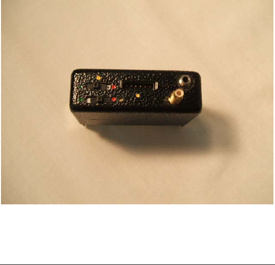
Figure 1, The Joey1W Transcorder

© TTI and Geonautics 6 Law Enforcement ONLY
The transmitter operating frequencies can be programmed through
HyperTerminal or may be programmed using any of TTI's Citation
series receivers or the PTX-100 programming module. The recorder
parameters are programmed through a PC running the supplied
proprietary
Joey
software.
This document explains how to operate the
Joey1W
, it’s accessories,
and the associated
Joey
software suite.

© TTI and Geonautics 7 Law Enforcement ONLY
1.1 Features
Features of the
Joey1W
include;
High quality audio recovery for both transmitter and recorder
Externally cabled microphone
Single channel, VHF-FM synthesized transmitter
Transmitter has own hardware ON/OFF switch
Program the transmitter directly from a TTI Citation Receiver
or TTI PTX-100 Programmer
Companded recorded audio for increased intelligibility
Self powered, onboard real-time clock for increased integrity
Outstanding concealing abilities to enhance operational usability
Multiple recordings allowing stop / start operation
User programmable timer record modes
Recorder available in 64, 128, 256, 512, or 1024 MB storage
capacity
Extended record time capabilities
High speed USB interface for faster data transfers
Raw data download with audit trail identifiers for integrity
Industry standard WAV compatibility for easy distribution
1.2 Packing List
At the time of printing, a
J1W
standard kit contains the following
items,
J1W Kit Description
Joey J1W
Transcorder
Microphone (3ft cable)
Antenna
USB program & download cable (4½ft
cable)
Citation / PTX-100 Programming Cable
Joey
Software CD
TTI TX Programming Software
Authenticate CD
Plastic Accessory Box
Black Storage Box
Table 1, Joey1W Standard Packing List

© TTI and Geonautics 8 Law Enforcement ONLY
1.3 Using the J1W Transcorder
The
J1W
is designed to be used,
operationally in a stand alone configuration, or
in conjunction with its USB cable and a personal computer
for configuration, downloading and replay of stored audio, or
connected to a personal computer, TTI Citation Receiver, or
TTI PTX-100 for Transmitter Only Frequency Programming.
Before using the
J1R
in an operational environment, it should first be
run in PC Mode and the recorder configured using the accompanying
Joey
software. The Transmitter operating frequency must be
programmed separately.
NOTE: Transmitter must be switched OFF while operating in PC Mode.
1.4 PC Mode – Recorder Operation
Install the
Joey
software and USB device drivers.
Using the USB cable supplied, connect the
J1R
to the computer and
configure the unit to the desired operational parameters by running the
Joey
software. Make sure the Transmitter ON/OFF switch is in the OFF
position.
To connect the USB cable to the
Joey1W
, align the arrow and yellow
dot on the USB Cable 6 pin connector with the yellow dot 6 pin
connector of the
J1W
unit. If you attempt to install the cable upside
down, you will damage the
Joey1W
.

© TTI and Geonautics 9 Law Enforcement ONLY
Make sure that the connector makes contact head on with the
J1W
,
ensuring no twist in the connection which may result in connector
damage. Removal of cables also requires the connectors to come off
without much twist, so that damage does not occur to the unit.
When using the USB cable, the
Joey1W’s
recorder draws power
directly from the computer through the cable.
After you are finished configuring the
Joey1W
, disconnect the
recorder from the USB cable. The recorder will remember it’s
configuration parameters and will operate according to those
parameters the next time power is applied.
1.5 Stand Alone Mode
Once the recorder is configured using the
Joey
program and
transmitter frequency has been programmed using a Citation Receiver,
Personal Computer, or PTX-100 programmer. The transmitter and
recorder will remember and use the current configuration each and
every time power is applied to the unit.
1.5.1 Making the Connections
For an operation, you must decide how you want to configure your
J1R
.
1. No matter what, you must connect the antenna.
2. External tethered or internal microphone?
3. Is there a need for the optional, tethered remote ON/OFF switch?
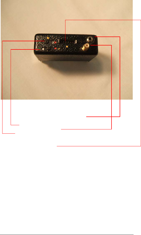
See the diagram below for connector placement on the
J1W
.

© TTI and Geonautics 10 Law Enforcement ONLY
Figure 2, J1W Connections
A: External Microphone Connector
B: Transmitter ON/OFF Switch
C. Antenna Connector
D: MASTER On/Off Switch
E: 6 Pin connector for recorder programming, or external
remote on/off switch.
Antenna
Connect the external antenna to the
J1W
by inserting the male end of
the SMC type antenna connector on the device to the female
connector end on the wire antenna. Twist the connector clockwise to
tighten, HAND TIGHT ONLY!
Microphone

© TTI and Geonautics 11 Law Enforcement ONLY
Determine which of the two microphone configurations are best for
your application: the long tethered remote microphone or the internal
microphone.
If you choose the internal microphone, you do not need to do
anything. If you choose the external microphone, connect the external
microphone by inserting the plug male end of the mini connector on
the microphone cable into the female jack found on the
J1W
. Push the
connectors firmly together. Twist the plug clockwise slightly to lock
the connector in place. HAND TIGHT ONLY! Switching between
the internal and external microphones is automatic and accomplished
when the external microphone plug is inserted into (or removed from)
the microphone jack on the J1W.
Power
IMPORTANT: Before applying power to the
J1W
ensure that:
a) The Transmitter On/Off Switch is OFF, or
b) An antenna is connected to the
J1W.
Never apply power to the
J1W
without an antenna connected.
The J1W is powered by two 9 volt batteries which will operate both
the transmitter and the recorder for up to 3 hours.
1.5.2 Microphone and Antenna Placement
As a general rule the external microphone should be as close as
possible to mouth level. Sound waves travel in straight lines and the
placement should reduce obvious obstructions. If a microphone is to
be placed behind a surface, which is not porous, a small pin hole
should be placed in the surface opposite the microphones diaphragm.

© TTI and Geonautics 12 Law Enforcement ONLY
Ensure that any material will not rub against the surface of the
microphone.
For maximum efficiency, the
J1W
antenna should be kept
vertical whenever possible. Placing the antenna on a metal
object may result in quite poor performance of the
J1W
’s
transmitter. The antenna should not be wrapped around the
J1W
, nor should it be coiled or bunched in a ball. The antenna
used for this transmitter must not be collocated or operating in
conjunction with any other antenna or transmitter. The antenna
must be installed to provide a separation distance of at least 20 cm
from all persons.
1.5.3 Operational Mode
When power is applied to the
J1W
via the master power switch, the
unit will wait for approximately three seconds, and then start to
record using its current configuration.
Note: The exception to this is if the unit has been previously
configured for timer mode. (See Error! Reference source not
found. Error! Reference source not found.)
Once the unit is recording, the transmitter will come on instantly when
the Transmitter Power Switch is turned ON (towards the red dot).
Removing power stops the recording and the RF transmissions.
Subsequent recordings and resumption of transmissions may be made
by re-applying power to the recorder. This is repeatable up until the
unit becomes full and cannot record any more audio. The transmitter
will still operate, even if the recorder is full..
When the operation is completed or the recorder becomes full, it
should be downloaded using the
Joey
program. The recorder does not
require power to retain its recordings and downloading can happen at
any time subsequent to a recording being made.

© TTI and Geonautics 13 Law Enforcement ONLY
Noteworthy Operational Considerations
Before ANY use of the
Joey1W
:
1. Verify the TRANSMITTER is functioning correctly by
checking its transmission with a good quality receiver
programmed to the correct frequency.
2. Verify the RECORDER portion by operating the
J1W
in PC
Mode and making a test recording.
3. ALWAYS use a fully charged battery at the start of any operation.
4. PRACTICE with this piece of equipment prior to official use.
1.6 Timer Mode
When configured to timer mode, the
J1W
’s recorder will sleep until
the next preset start time has been reached. After all timers have
expired, the
J1W
’s recorder remains in sleep mode until a power reset
returns it to normal operation. If all start times have expired prior to
power being applied, the
J1W
’s recorder operates as if no timers had
been set.
1.7 Recording Quality
The
Joey1W
’s
audio front end and data storage algorithms are
designed to provide the user with a range of quality options ranging
from direct storage of the 8 bit samples (Linear Pulse Code
Modulation, LPCM) to Adaptive Differential Pulse Code Modulation
(ADPCM) for the 4 bit modes.
Sampling Speed (kHz) Typical Bandwidth (Hz)
8 3200
11 4700
Table 2, Typical Joey1W Recorder Audio Bandwidths
1.8 Recording Times

© TTI and Geonautics 14 Law Enforcement ONLY
The
Joey1W
will yield the following recording times based on its
recording profile,
Quality Bits 64 MB 128 MB 256 MB 512 MB
8 bit – LPCM 1.7 hrs 3.3 hrs 6.6 hrs 13.2 hrs
11 kHz
Mono 4 bit – ADPCM 3.3 hrs 6.6 hrs 13.2 hrs 26.4 hrs
8 bit – LPCM 2.3 hrs 4.6 hrs 9.1 hrs 18.2 hrs
8 kHz
Mono 4 bit – ADPCM 4.6 hrs 9.1 hrs 18.2 hrs 36.4 hrs
Table 3, Recording Times
The new 1024 MB J1W will double the times found in the chart for
the 512 MB unit.
The total recording time is not diminished if more than one recording
is made on the
Joey1W
to make up the total.
1.9 Power Considerations
The J1W will operate continuously with two new 9volt batteries and
both the recorder operating and the transmitter operating for up to 3
hours.

© TTI and Geonautics 15 Law Enforcement ONLY
The following table is indicative of the typical recording times
available using some standard battery configurations.
Battery Cell
Type Operation mAHrs Timer
Correction Hrs
1 x 9v 9 VDC
Alkaline
Recorder
only 565 4 hrs per day 60
1 x 9v 9 VDC
Alkaline
Transmit
and
Record
565 0.5 hrs per day 3
Table 4, Battery Life
When the
J1W
recorder is used in timer mode), the expected operating
hours must be reduced.
1.10 Concealment and Tactical Issues
Concealment and tactical issues surrounding the use of the
Joey1W
are beyond the scope of this guide.
1.10.1 Range of the J1W Transmitter
It is impossible to state absolutes about how far an RF transmitter like
the
J1W
will transmit. Many variables affect the range of a device
including buildings, trees, weather, construction materials,
installation, etc.
All things being perfect (meaning transmissions are outdoors over flat
terrain with no obstructions), a
Joey1W
should be able to easily
transmit over a mile. You should expect less distance than that
however, in a real world operation.

© TTI and Geonautics 16 Law Enforcement ONLY
One of the most important variables, and one that the operator can
actually control, is the placement of the receiver and the receiving
antenna. A good rule to follow is the higher the antenna placement, the
better chance you have of quality reception. This alone will increase your
operating range. Just having the
J1W
in an ideal location is not enough.

© TTI and Geonautics 17 Law Enforcement ONLY