Tadano RCSFR1 Remote Control Receiver for Crane User Manual USERS MANUAL 2
Tadano Ltd. Remote Control Receiver for Crane USERS MANUAL 2
Tadano >
Contents
- 1. USERS MANUAL 1
- 2. USERS MANUAL 2
USERS MANUAL 2

M037920E
Contents 1 Contents
Contents
Safety Caution ・・・・・・・・・・・・・・・・・・・・・・・・・・・・・・・・・・・・・・・・・・・・・・・・ A-1
Preface・・・・・・・・・・・・・・・・・・・・・・・・・・・・・・・・・・・・・・・・・・・・・・・・・・・・・・・ 2
Configurations of Radio-control System ・・・・・・・・・・・・・・・・・・・・・・・・ 3
Names and Functions of Each Section・・・・・・・・・・・・・・・・・・・・・・・・・・ 4
1. Radio-control Block ・・・・・・・・・・・・・・・・・・・・・・・・・・・・・・・・・・・・・・・ 4
2. Crane ・・・・・・・・・・・・・・・・・・・・・・・・・・・・・・・・・・・・・・・・・・・・・・・・・・・ 7
Safety Functions of Radio-control System ・・・・・・・・・・・・・・・・・・・・・・ 8
1. Auto Power-off Function ・・・・・・・・・・・・・・・・・・・・・・・・・・・・・・・・・・・ 8
2. Switch Failure Detection Function・・・・・・・・・・・・・・・・・・・・・・・・・・・ 8
3. Continual Operation Restriction Function ・・・・・・・・・・・・・・・・・・・・ 9
4. Instant Stop Alarm Function・・・・・・・・・・・・・・・・・・・・・・・・・・・・・・・・ 9
5. Alarm Function ・・・・・・・・・・・・・・・・・・・・・・・・・・・・・・・・・・・・・・・・・・・ 10
Radio-control ・・・・・・・・・・・・・・・・・・・・・・・・・・・・・・・・・・・・・・・・・・・・・・・・・ 11
1. Preparation for Radio-control Operation ・・・・・・・・・・・・・・・・・・・・・ 11
2. How to Operate the Radio-control・・・・・・・・・・・・・・・・・・・・・・・・・・・ 13
3. Changing Speed Mode ・・・・・・・・・・・・・・・・・・・・・・・・・・・・・・・・・・・・ 15
4. Engine Start-up Operation ・・・・・・・・・・・・・・・・・・・・・・・・・・・・・・・・・ 16
5. Emergency Stop Operation ・・・・・・・・・・・・・・・・・・・・・・・・・・・・・・・・ 16
Manual Operation ・・・・・・・・・・・・・・・・・・・・・・・・・・・・・・・・・・・・・・・・・・・・・ 17
Battery Replacement for Transmitter ・・・・・・・・・・・・・・・・・・・・・・・・・・・ 18
1. Battery Replacement Timing ・・・・・・・・・・・・・・・・・・・・・・・・・・・・・・・ 18
2. How to Replace Batteries・・・・・・・・・・・・・・・・・・・・・・・・・・・・・・・・・・ 18
Measures for Emergency Case・・・・・・・・・・・・・・・・・・・・・・・・・・・・・・・・・ 19
1. When Radio-Control Operation is Impossible ・・・・・・・・・・・・・・・・・ 19
2. If the Radio-control is not Possible ・・・・・・・・・・・・・・・・・・・・・・・・・・ 22
Troubleshooting Guide ・・・・・・・・・・・・・・・・・・・・・・・・・・・・・・・・・・・・・・・・ 23
Daily Inspection・・・・・・・・・・・・・・・・・・・・・・・・・・・・・・・・・・・・・・・・・・・・・・・ 25
M037930E
Preface 2 Preface
Preface
This operation and maintenance manual is for safe and proper operation and
inspection/maintenance of the radio-control system whose model is shown in the following
table.
Refer to the operation and maintenance manual of the main unit of the crane for operation
and inspection/maintenance of the main unit.
Applicable model
Transmitter RCS-FT1
Communication unit RCS-FR1
Radio-control system
Control unit RCS-FC1
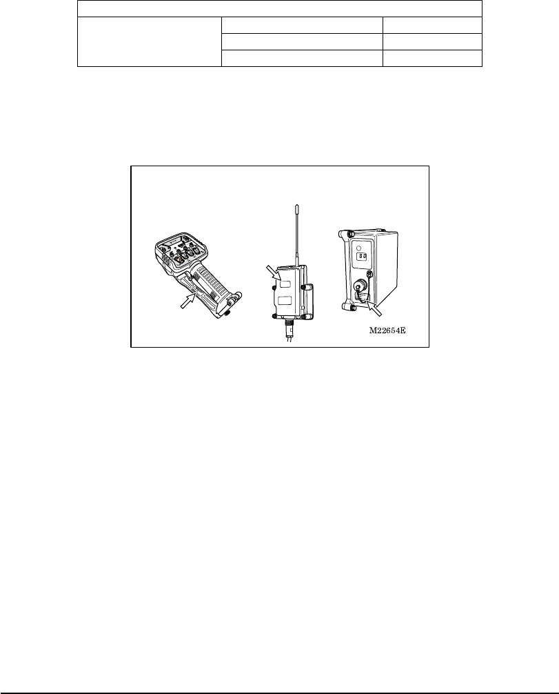
Confirm the model of your radio-control system with the nameplates shown in the following
illustrations.
Illustrations in this manual may differ from the actual products in details. Note that the
illustrations for explanation purposes are sometimes drawn without any cover or guard.
Note that the products may be subject to modifications that are not reflected in this manual,
because of product improvement.
When transferring the crane to another party, transfer this manual also together with the
crane.
Should you have any comments or inquiries on the delivered crane or this manual, contact
the nearest TADANO distributor or dealer.
Transmitter Communication unit Control unit
M037940E
Configurations of Radio-control System 3 Configurations of Radio-control System
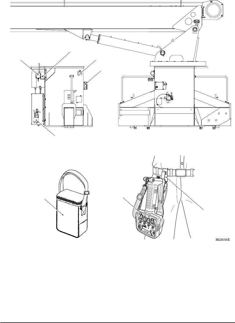
Configurations of Radio-control System
Control unit
Communication unit Speaker
(for alarm)
Emergency stop lamp
Radio control valve
Transmitter
Portable hook
Transmitter
storing bag
M037950E
Names and Functions of Each Part 4 Names and Functions of Each Part
Names and Functions of Each Part
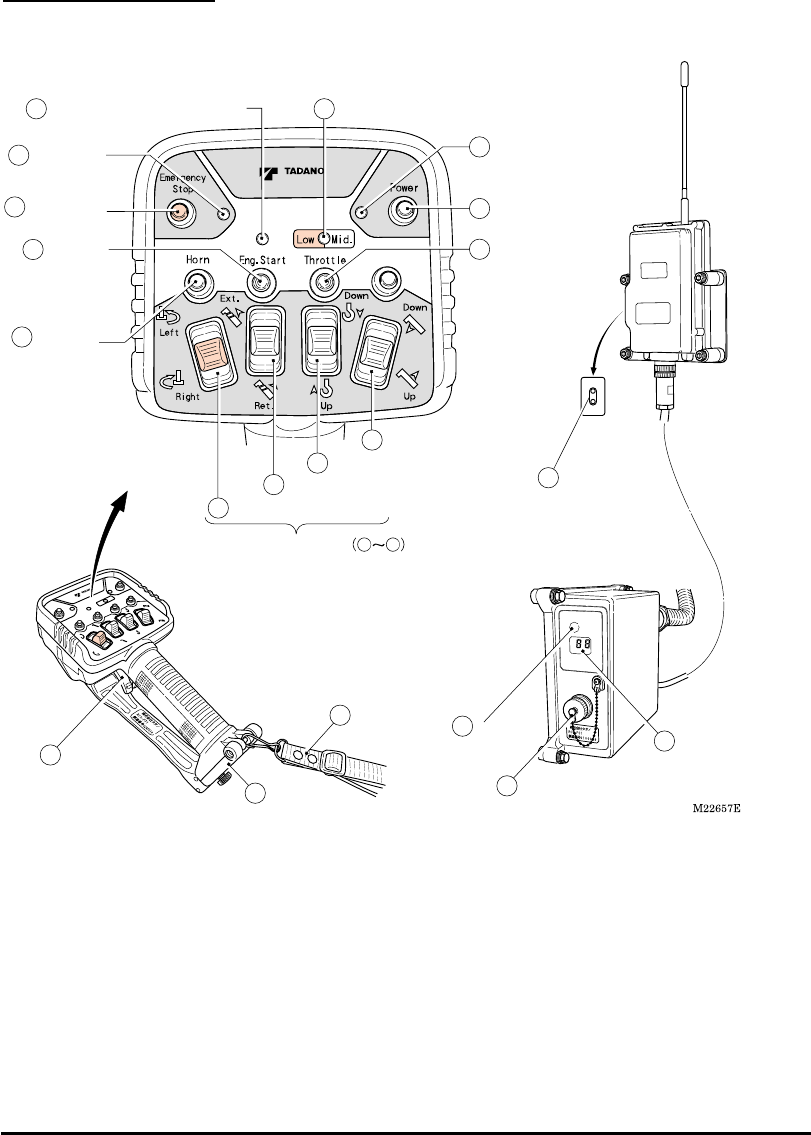
1. Radio-control Block
4 Power switch
5 Speed mode
switch
3 Power LED (Red)
13 Emergency
stop LED (Red)
11 Engine
start switch
10 Horn switch
12 Emergency
stop switch
1 Engine start LED (Red/Green) 2 Speed mode LED (Red/Green)
6 Elevation selection switch
9 Swing selection switch
7 Hook selection switch
8 Extension selection switch
16 Speed
control lever
18 Connector for remote-control operation
19 Reception
lamp 17 Mode indicator lamp
15 Battery cover
TransmitterCommunication Unit
Control Unit
14 Strap
20 Communication
unit LED
(Red/Green)
0200ES2
RCS-FR1
IC
:
-RCSFR1
FCC ID
:
-RCS-FR1
Motion selection switches 69

M037950E
Names and Functions of Each Part 5 Names and Functions of Each Part
1. Engine Start LED
The LED shows the condition of the engine
start switch.
・ When the switch is not operated: Turned
off
・ When the switch is operated: Turned on
(Red)
2. Speed Mode LED
The LED shows the speed modes.
・ At high-speed mode: Turned off
・ At medium-speed mode: Turned on
(Green)
・ At low-speed mode: Turned on (Red)
3. Power LED
The LED shows the power ON/OFF of the
transmitter and battery consumption
condition.
・ At power OFF: Turned off
・ At power ON: Turned on (Red)
・ At battery exhaustion: Flashing (Red)
4. Power Switch
This is the switch for power ON/OFF of the
transmitter.
When the power switch is pressed while
the radio-control /manual changeover
switch of the crane is turned to “Radio”
position after PTO is set to “Engaged” state,
the power of the transmitter is turned on
and the power LED lights up.
When the power switch is pressed once
again, the power is turned off and the
power LED turns off.
5. Speed Mode Switch
This is the switch to select the speed mode.
Every time the switch is pressed, the mode
changes in the order of: “low-speed” →
“medium-speed” → “high-speed”
→“low-speed” •••••. At the same time, the
speed mode LED changes in the order of:
“turned on in red” → “turned on in green” →
“turned off” → “turned on in red” •••••.
6. Elevation Selection Switch
7. Hook Selection Switch
8. Extension Selection Switch
9. Swing Selection Switch
These are the motion selection switches for
the crane operation. When the speed
control lever is pulled after the motion
selection switch is changed, the crane can
be operated.
10. Horn Switch
When the switch is pressed, the vehicle’s
horn sounds.
11. Engine Start Switch
This is the switch to output the engine start
signal. When the switch is pressed, the
engine starts up.
The engine start-up is disabled under
the emergency stop state.
12. Emergency Stop Switch
Pressing the switch causes an emergency
stop and all the crane operation stops. At
the same time, the emergency stop LED
and emergency stop lamp of the crane light
up.
When the switch is pressed once again, the
emergency stop state is released, and the
emergency stop LED and emergency stop
lamp of the crane turn off.
13. Emergency Stop LED
The LED shows the emergency stop state.
・ Under normal condition: Turned off
・ Under emergency stop state: Turned on
(Red)
14. Strap
The strap is for portable use of the
transmitter. Hook the transmitter onto a belt
on your waist or hang it from your neck by
extending the strap.
15. Battery Cover
This is used when replacing the batteries.
16. Speed Control Lever
This is the lever to adjust operation speeds
of the crane.
According to the pulling amount of the lever,
the engine speed increases to increase the
speed of the crane.

M037950E
Names and Functions of Each Part 6 Names and Functions of Each Part
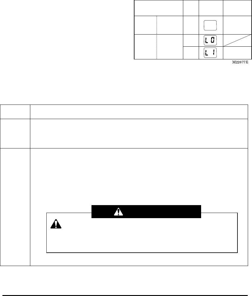
17. Mode Indicator Lamp
The lamp indicates the current operation
mode.
・ At power on of the control unit: “L0”
・ At radio-control mode: “L1”
At error occurrence, an error number is
displayed.
18. Connector for Remote-control
Operation
This is the connector to connect the
remote-control transmitter when the
remote-control is used.
The connector is not used for this
system.
19. Reception Lamp
The lamp lights up while operation signals
are received from the radio-control
transmitter.
When the power of the control unit is
turned on while the radio-control
/manual changeover switch of the crane
is turned to the “Radio” position after
PTO is set to “Engaged” state, the lamp
also lights up once.
20. Communication Unit LED
The LED shows the power ON/OFF of the
communication unit and communication
conditions.
・ “Upper side”: Power LED
When the power is supplied to the
communication unit from the control unit
while the radio-control /manual
changeover switch of the crane is turned
to “Radio” position after PTO is set to
“Engaged” state: Turned on (Red)
At error: Turned on (Orange)
・ “Lower side”: Radio wave LED
Under communication: Turned on
(Green)
Before communication, at
communication disconnected, and at
power OFF of the transmitter: Turned off
At error: Turned on (Orange)
When communication is interrupted
during the operation: Flashing (Green)
M037950E
Names and Functions of Each Part 7 Names and Functions of Each Part
2. Crane
SPEAKER
SPEAKER
ON
OFF
Radio
Manual
2 Radio control/manual
changeover switch
3 Emergency
stop lamp
4 Speaker
1 Speaker
switch
1. Speaker Switch
This is the switch to select output/stop o
f
the alarm.
“ON”: Alarm sounds
“OFF”: Alarm stops
2. Radio-control/Manual Changeove
r
Switch
This is the switch to select radio-control
operation/manual operation.
“Radio”: Radio-control operation
“Manual”: Manual operation
3. Emergency Stop Lamp
The LED shows the emergency stop state.
・ Under normal condition: Turned off
・ Under emergency stop state: Turned on
(Yellow)
The lamp shows the same indication as
the emergency stop LED of the radio-
control transmitter.
4. Speaker
The speaker outputs an alarm sound at
occurrence of a problem, at wrong
operation, and to call attention for proper
o
p
erations.
M037960E
Safety Functions of Radio-control System 8 Safety Functions of Radio-control System
Safety Functions of Radio-control System
The radio-control system has the following functions to realize safety operations.
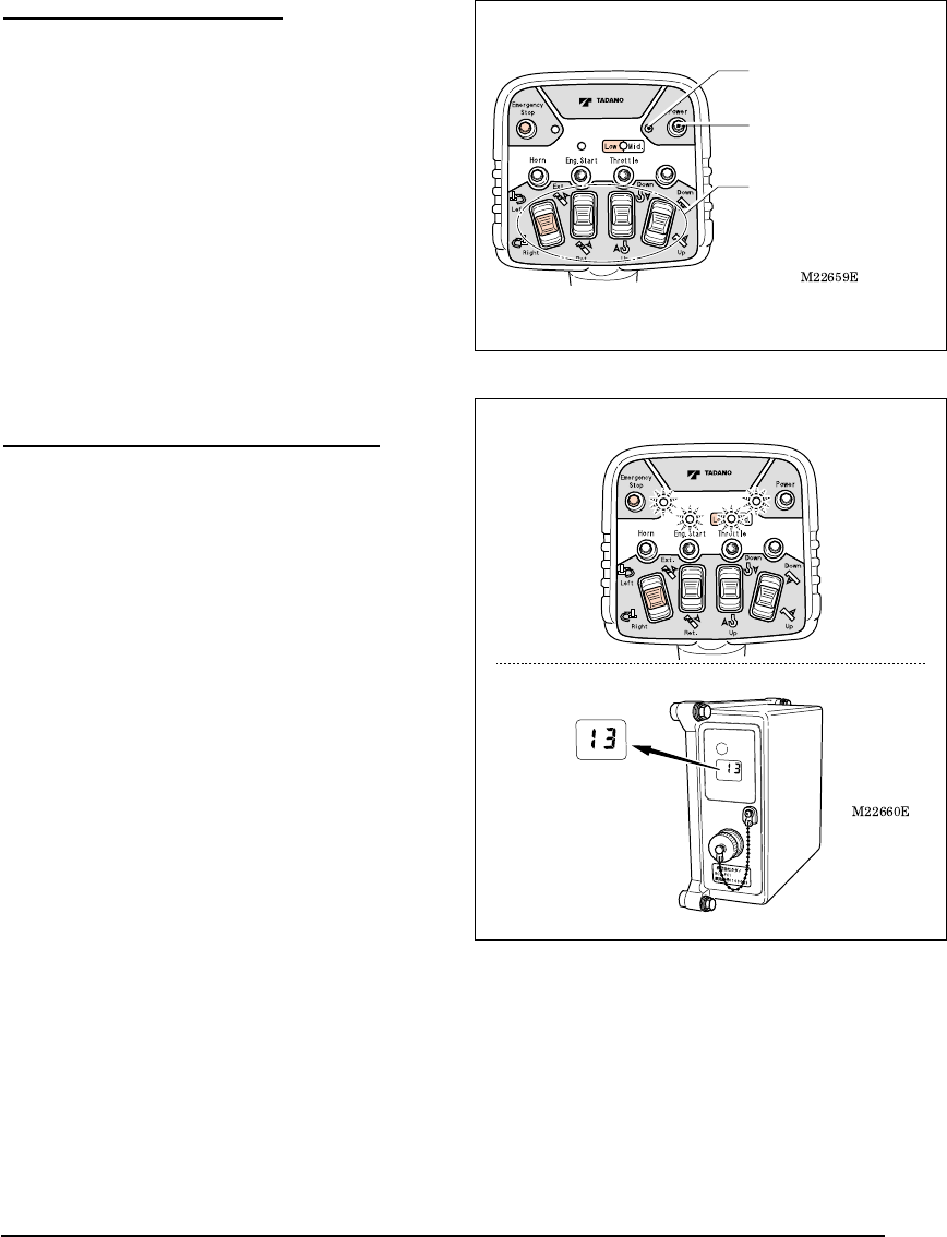
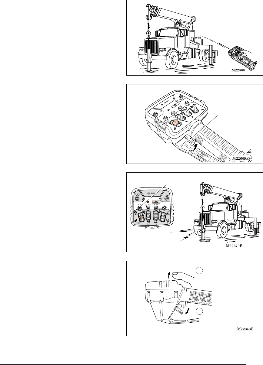
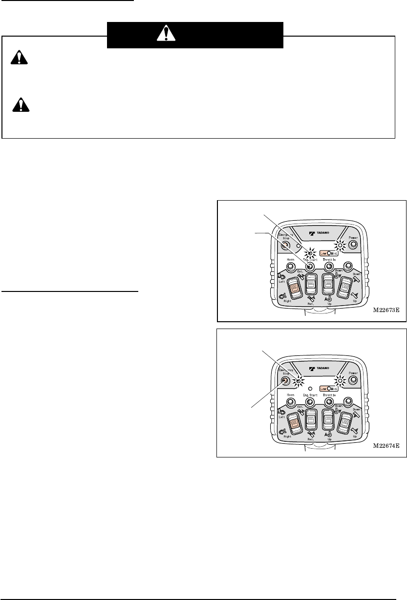
1. Auto Power-off Function
When the motion selection switch is not
operated for approximately one hour, the
power of the transmitter is automatically
turned off to save battery consumption.
The power LED of the transmitter is turned
off, and the mode indicator lamp of the
control unit changes from the radio-control
mode “L1” to the manual mode “L0”.
To resume the radio-control operation,
press the power switch once again to turn
on the power LED to set to the radio-control
mode.
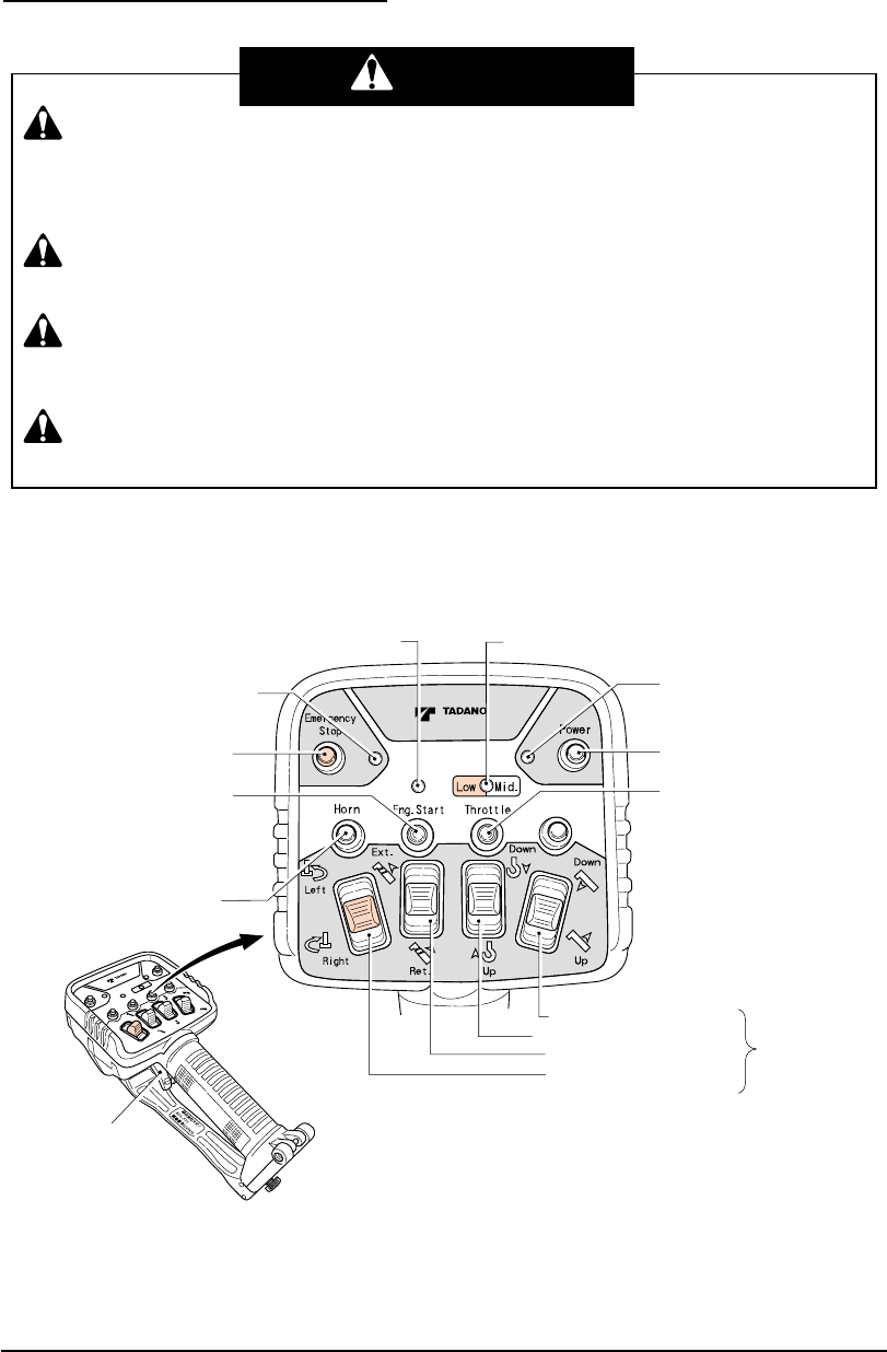
2. Switch Failure Detection Function
Error is displayed when the power of the
transmitter is turned on while the switches or
speed control lever is operated.
Four LEDs on the transmitter flash to show
the failure condition. In addition, the mode
indicator lamp of the control unit displays
the error number “13”, and both the
radio-control operation and manual
operation are disabled. (Refer to the
chapter of “Measures for Emergency
Case”)
When the power of the transmitter is turned
off, the mode indicator lamp of the control
unit changes to “L0”.
To perform a radio-control operation, press
the power switch while releasing your finger
from the other switches and the speed
control lever.
Power switch
Power LED
Motion selection switch
Error number
is displayed
M037960E
Safety Functions of Radio-control System 9 Safety Functions of Radio-control System
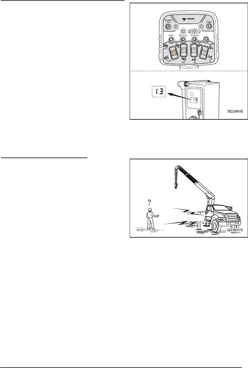
3. Continual Operation Restriction Function
Error is displayed when any of the motion
selection switches is kept in the operation
state for approximately five minutes due to a
failure, trapped dirt or the like.
Four LEDs on the transmitter flash to show
the failure condition. In addition, the mode
indicator lamp of the control unit displays
the error number “13”, and both the
radio-control operation and manual
operation are disabled. (Refer to the
chapter of “Measures for Emergency
Case”)
When the power of the transmitter is turned
off, the mode indicator lamp of the control
unit changes to “L0”.
To resume the radio-control operation, turn
the power on once again after confirming
the position of the motion selection
switches.
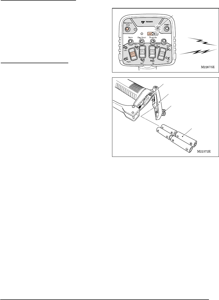
4. Instant Stop Alarm Function
If the radio wave from the transmitter is
hindered during the radio-control operations
due to changing surrounding conditions and
the like, the speaker outputs a “beep” alarm.
Condition of the crane is as follows
according to the number of beeps of the
alarm.
(1) “Beep”
The crane continues to work although there
is a warning of poor radio wave
transmission.
(2) “Beep, Beep”
The crane operation stops when two
continual alarms sound.
In either case the warning is of poor radio
wave transmission condition. Take measures
such as reducing the distance between the
transmitter and the communication unit.
Error number
is displayed
"Beep, Beep"
M037960E
Safety Functions of Radio-control System 10 Safety Functions of Radio-control System
5. Alarm Function
The following alarms sound when the system
has a problem, when a wrong operation is
made, or to call attention for proper operations.
Take appropriate measures according to the
following tables when the alarm sounds.
(1) At the time of abnormal stop of the radio-control system:
Warning sound Beep (Three times)
Warning timing When the computer judges that serious trouble has occurred to the
system
Crane
operation
The radio-control operation is disabled.
Measure Refer to the chapter of “Measures for Emergency Case”
(2) At the time of a problem occurring when the operation lever is at the neutral position
Warning sound Beep (Three times)
Warning timing When the operation lever of the crane does not return to the neutral
position even after the motion selection switch of the transmitter is
returned to the neutral position.
Crane
operation
The radio-control operation is disabled.
Measure Refer to the chapter of “Measures for Emergency Case”
(3) Battery exhaustion warning
Warning sound Two-tone alarm (once)
Warning timing When the motion selection switch of the transmitter is operated under the
low battery-voltage condition of the transmitter.
Measure Refer to the chapter of “Battery Replacement for Transmitter”
(4) At the set of emergency stop state
Warning sound Beep (Once)
Warning timing When the operation to set the emergency stop state is made.
(5) At the release of emergency sop state
Warning sound Two-tone alarm (once)
Warning timing When the operation to release the emergency stop state is made.
No alarm sounds when the speaker switch is turned “OFF”. Since it is an
important alarm, turn the speaker switch “ON” except for special cases.
Operation should be made with special care when the switch needs to be turned off due
to noise prevention at nighttime operation and the like.
In addition, make sure that the switch is returned to “ON” position after the operation.
SPEAKER
Speaker
switch
Warning
M037970E
Radio-control 11 Radio-control
Radio-control
[NOTE]
Even after the radio-control transmitter is turned OFF under the condition where the
radio wave is out of reach, the control unit still remains on in the radio-control mode.
Make sure to confirm that the mode indicator lamp of the control unit indicates “L0” after
the radio-control operation is completed (or after the power of the transmitter is turned
OFF).
1. Preparation for Radio-control Operation
Confirm that each lever is at the following position before starting up the engine.
Each operation lever for extension/winch/elevation/swing/jack ••••• “Neutral”
PTO lever (Switch) ••••• “Disconnected”
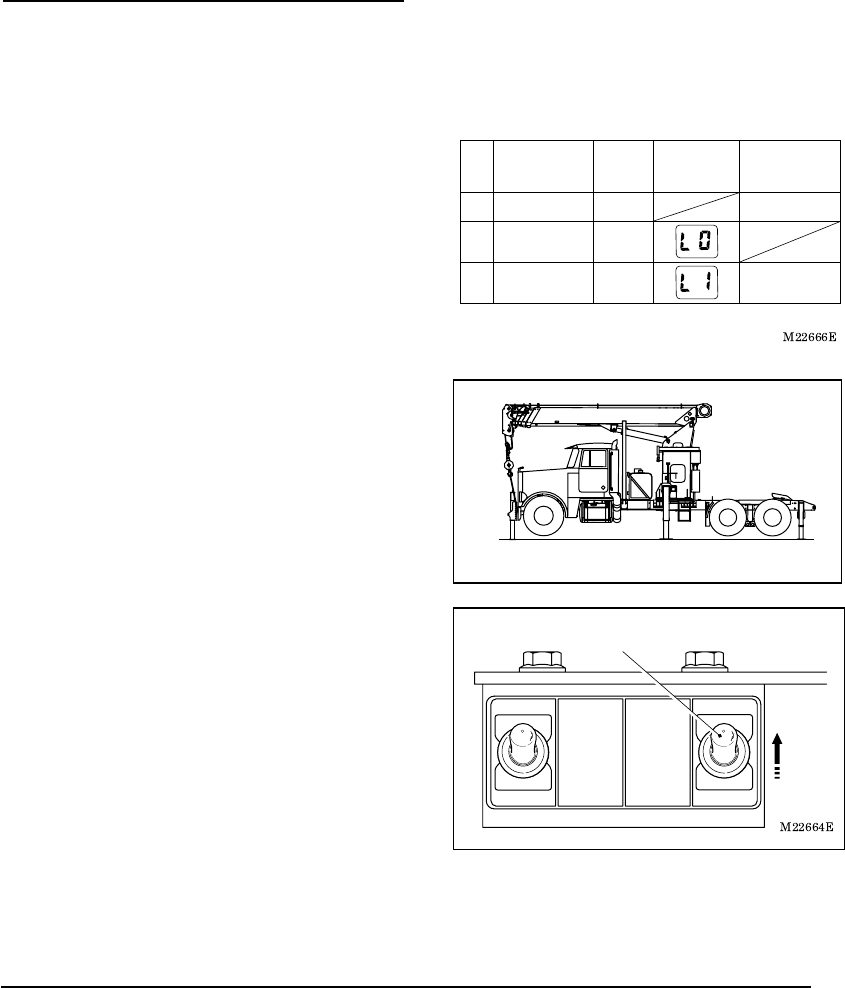
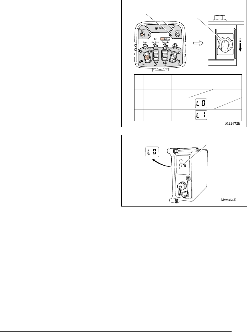
Operation mode changes as is shown in the
figure according to the PTO operation,
operation of the radio-control /manual
changeover switch, and power ON/OFF of
the radio-control transmitter.
In addition, an indication on the mode
indicator lamp of the control unit changes as
the figure shows.
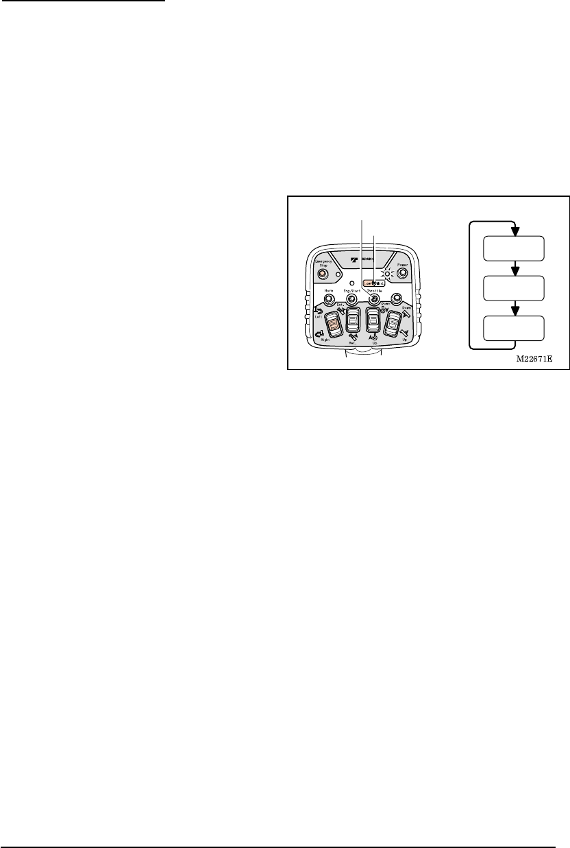
1. Start up the engine and turn PTO to
“Connected (ON)” position.
Confirm that the radio-control /manual
changeover switch is on “Manual” position.
2. After extending the outriggers, extend the jacks
and set the crane level.
3. Turn the radio-control /manual changeover
switch to “Radio” position.
When the switch is turned to “Radio” position,
the power of the control unit is turned ON.
Radio-control/manual changeover switch
M22663
M037970E
Radio-control 12 Radio-control
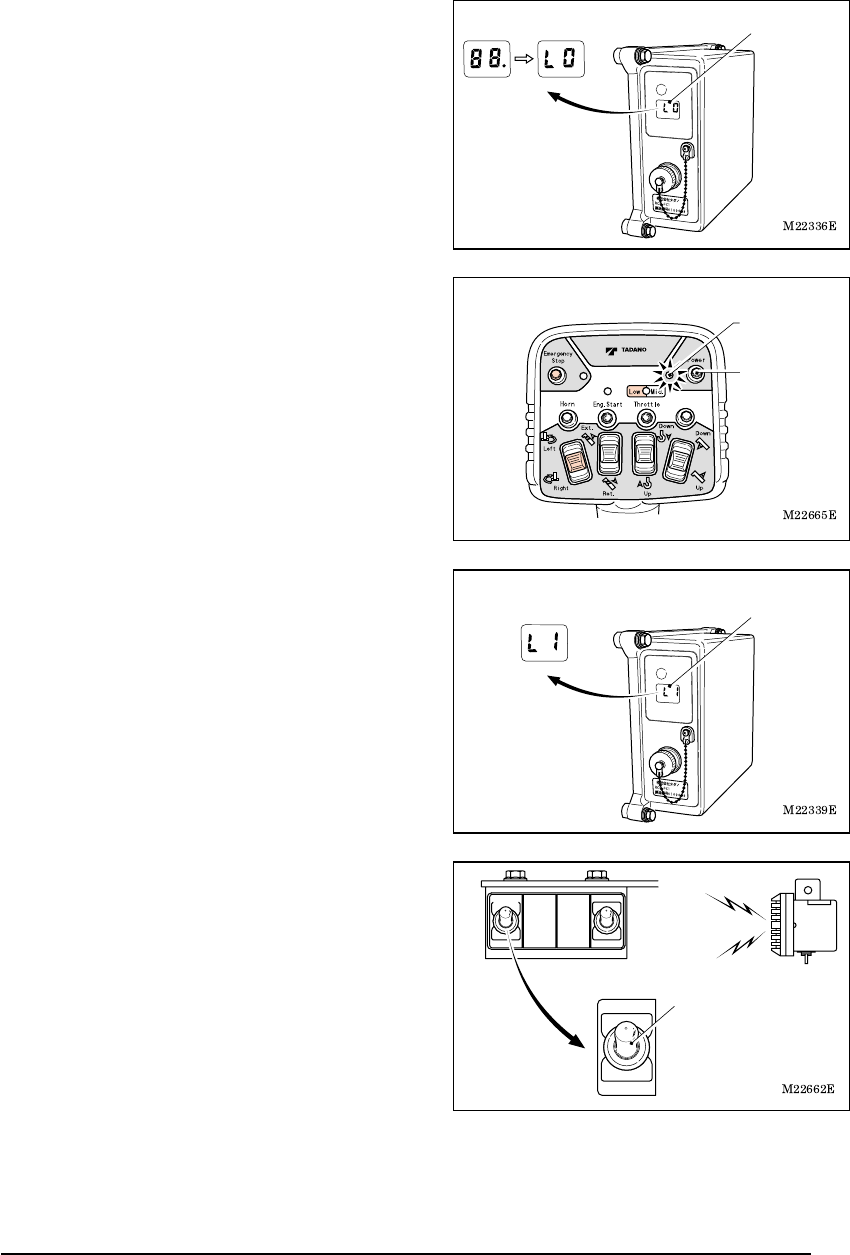
4. Confirm that the mode indicator lamp of the
control unit displays “L0”.
The lamp displays “L0” after displaying “88.”
(All light up).
5. Press the power switch to turn on the power of
the transmitter. The power LED of the transmitter
lights up.
If the power switch is pressed while other
switches or the speed control lever is under
operation, the switch failure detection function
works to indicate the error state. (Refer to the
chapter of “Safety Functions of Radio-control
System”). Do not touch any other switch or
lever than the power switch.
6. Confirm that the mode indicator lamp of the
control unit has changed from “L0” to the
radio-control mode “L1”.
7. Confirm that the speaker switch is turned “ON”.
No alarm sounds if the speaker switch is
“OFF”.
Mode indicator lamp
Power switch
Power LED
Mode indicator lamp
SPEAKER
Speaker
switch
M037970E
Radio-control 13 Radio-control
2. How to Operate the Radio-control
(1) Operation device
Power switch
Speed mode switch
Power LED
Emergency stop LED
Engine
start switch
Emergency
stop switch
Engine start LED Speed mode LED
Elevation selection switch
Swing selection switch
Hook selection switch
Extension selection switch
Speed
control lever
Motion selection
switches
M22667E
Horn
switch
- Before starting the crane operation, confirm whether or not it is possible to make
each motion of the crane normally by making the following operations: Extending
and retracting of the boom, raising and lowering of the boom, hoisting up and
down the hook, and turning of the hook.
- It is dangerous to rapidly pull the speed control lever, causing sudden movemen
t
of the crane. Pull the lever slowly. Also, release the speed control lever slowly.
- It is dangerous to release your finger from the motion selection switch while the
speed control lever is pulled, since it causes a shock. Release your finger from the
motion selection switch after letting go of the speed control lever.
- While the radio-control operation is made, the manual operation lever moves
correspondingly. Do not touch the manual operation lever.
Warning
M037970E
Radio-control 14 Radio-control
(2) Basic operations
1. Operate the motion selection switch while
pointing the transmitter in the direction of the
crane.
When the motion selection switch is
operated, the engine speed increases
slightly higher than the idling speed.
2. Pull the speed control lever slowly. Then the
crane starts to move.
The engine speed increases according to
the amount the lever is pulled. Adjust the
moving speed of the crane with the speed
control lever.
3. To call the attention of the surrounding
people during the operation, press the horn
switch. Then the vehicle’s horn beeps.
4. To stop the crane operation, release the
speed control lever slowly. The operation
stops when the lever is released.
Then release the motion selection switch.
Release the speed
control lever.
Release your finger
from the motion
selection switch.
Horn switch
Speed
control lever
M037970E
Radio-control 15 Radio-control
3. Changing Speed Mode
With the speed mode switch, operating speed of the crane can be changed to three levels:
High-speed, medium-speed and low-speed. Select the high-speed mode when the crane
needs to be used under normal conditions, the medium-speed mode when the crane needs
to be used with medium-speed range of the engine, and low-speed mode when the crane
needs to be used with low-speed (at idle up) or when noise prevention is necessary during
nighttime operation and the like.
The speed mode is memorized even after the power is turned off. Next time the power
of the transmitter is turned on; the previously selected speed mode is set.
1. Press the speed mode switch while the
power LED of the transmitter is turned on.
Every time the switch is pressed, an indication
of the speed mode LED changes in the
following order and the speed mode changes
accordingly.
(1) At high-speed mode: LED off
(2) At low-speed mode: LED on (Red)
(3) At medium-speed mode: LED on (Green)
Speed mode switch
Speed mode LED
Low-speed mode
(LED (red) on)
Medium-speed mode
(LED (green) on)
High-speed mode
(LED off)
M037970E
Radio-control 16 Radio-control
4. Engine Start-up Operation
[NOTE]
Engine start-up operation is disabled under the emergency stop state. Release
the emergency stop state before the operation.
Press the engine start switch after conforming
that the engine is stopped. The engine start
LED lights up while the switch is pressed and
the engine starts.
After the engine starts up, quickly release
your finger from the switch.
5. Emergency Stop Operation
When the control cannot be made through the
radio-control operation, or when the
surrounding situation becomes dangerous,
press the emergency stop switch. If the switch
is pressed, the engine stops, which stops the
crane operation.
When the switch is pressed, the
emergency stop LED and emergency
stop lamp of the crane light up to indicate
the emergency stop state.
Beep alarm sounds.
How to Release Emergency Stop
Press the switch once again. Then the
emergency stop LED and emergency stop
lamp of the crane turn off and the emergency
stop state is released.
Two-tone alarm sounds.
The emergency stop state is also released when the switch of the control unit is turned
off after the radio-control /manual changeover switch is turned to “Manual” position.
It is dangerous to start up the engine while the motion selection switch of the
manual operation lever or transmitter is under operation, causing sudden
movement of the crane. Start-up the engine after confirming that the operation
levers and motion selection switches are in the neutral position.
The engine is damaged if the starting-up operation of the engine is made while
the engine is rotating. Start-up the engine after confirming that the engine has
stopped.
Engine start LED
Engine
start
switch
Emergency stop LED
Emergency
stop switch
Warning
M037980E
Manual Operation 17 Manual Operation
Manual Operation
[NOTE]
To change from the radio-control
operation to manual operation, turn off
the power of the radio-control transmitter,
and then turn the radio-control /manual
changeover switch to the “Manual”
position.
Even after the radio-control transmitter is
turned off under the condition where the
radio wave is out of reach, the control unit
still appears to be on, in the radio-control
mode. Make sure to confirm that the
mode indicator lamp of the control unit
indicates “L0” after the radio-control
operation is completed (or after the
power of the transmitter is turned off).
Power LED (Turned off)
Power switch
Radio
Manual
Radio-control/manual
changeover switch
PTO
Transmitter
power
Mode
indicator lamp
Radio-control
/manual
changeover switch
ON
Manual operation
Radio-control
operation
OFFManual
ON OFFRadio
ON ONRadio
Operation
mode
Mode indicator lamp
M037990E
Battery Replacement for Transmitter 18 Battery Replacement for Transmitter
Battery Replacement for Transmitter
1. Battery Replacement Timing
Replace the batteries in the following cases.
(1) When the power LED of the transmitter
flashes.
(2) When the alarm (which has a “two-tone”
sound) sounds while the motion selection
switch is operated.
The power LED also flashes in this case.
2. How to Replace Batteries
[NOTE]
Inserting the batteries incorrectly for plus
(+) and minus (-) may cause a liquid spill,
ignition, heat generation, and burst.
Insert the batteries according to the
direction plate.
If the battery cover is loosely fixed, water
may enter inside and cause a problem.
Fasten the fixing screw securely.
1. Open the batteries cover and remove the
old batteries.
2. After replacing the new batteries, close the
battery cover and fasten the fixing screw.
Use four AA-size batteries.
Do not mix any old or different types.
Two-tone Alarm
Power LED
(Flashing)
Fixing screw
Battery cover
AA-size battery
Direction plate
M038000E
Measures for Emergency Case 19 Measures for Emergency Case
Measures for Emergency Case
1. When Radio-control Operation is Impossible
The radio-control operation is electrically made with the radio-control system. Therefore, a
part or the whole of the radio-control operation becomes impossible when the radio-control
system has a problem.
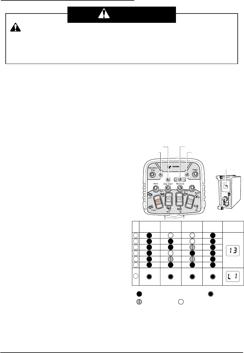
If a problem of the radio-control operation is recognized, confirm the operation of the four
LEDs of the transmitter and the mode indicator lamp of the control unit.
(1) If the LED of the transmitter flashes
・ If the power of the transmitter is turned on
while the motion selection switch is
operated, indications (2) as shown in the
table are displayed.
If the power of the transmitter is turned on
while the speed control lever is operated,
indications (4) as shown in the table are
displayed.
If the power of the transmitter is turned on
while the motion selection switch and
speed control lever are operated,
indications (1) as shown in the table are
displayed.
In either case, once again turn the power
on.
・ If the power of the transmitter is turned on
while the push switch (the horn, engine
start and speed mode) is operated,
indications (3) as shown in the table are
displayed.
After confirming the switch, once again turn
the power on.
・ If the motion selection switch is kept under
the operation state approximately for five
minutes due to a failure, trapped dirt or the
like, indications (2) as shown in the table
are displayed. After confirming the switch,
once again turn the power on.
Depending on the failure conditions, changing to the manual operation may not
restore the normal operation.
Check the LED indications of the transmitter or the error number on the mode
indicator lamp of the control unit in order to take the correct measure for the erro
r
number.
Warning
M22676E
Flashing red (with short cycle) Flashing red (with long cycle)
Flashing orange Flashing green
Mode indicator
lamp
Transmitter
Control unit
Engine start
LED Speed mode LED
Emergency
stop LED Power LED
Emergency
stop LED
I / R Engine start
LED
Speed
mode LED Power LED Mode
indicator lamp
* I / R : Indication priority
M038000E
Measures for Emergency Case 20 Measures for Emergency Case
If the normal operation is not restored or if
the indications (5) – (7) as shown in the
table remain to be displayed even after the
above measures are taken, quickly stow
the crane with the manual operation. Then
have the crane and radio-control system
inspected /repaired at the nearest
TADANO distributor or dealer.
(2) When the mode indicator lamp of the control unit displays an error number
The mode indicator lamp of the control unit
displays indications as are shown in the
figure to the right according to the
operational conditions.
If the mode indicator lamp displays the
indications not listed in the figure to the right,
the radio-control system has a problem.
Take an appropriate measure according to
the following table.
If more than two problems occur, each error number flashes in turn.
If the normal operation is not restored even after the measures in the following table are
taken, quickly stow the crane. Then, have the crane and radio-control system
inspected/repaired at the nearest TADANO distributor or dealer.
Error
number
Trouble and measure
13 After releasing your fingers from the switch of the transmitter and speed control
lever, turn on the power of the transmitter.
If the above does not restore the normal operation, the radio-control operation
is impossible. Change to the manual operation and operate the crane.
30-33 After the operation lever that corresponds to the error number is manually
returned to the neutral position, check if the error number disappears. When the
mode indicator lamp displays “L1” and when the error number does not
reappear after operation is started, the operation can be continued.
If the operation lever cannot be returned to the neutral position or if the error
number does not disappear, the radio-control operation of the part that has a
problem is not possible. Change to the manual operation and then operate the
crane.
Transmitter
power
Mode indicator
lamp
Radio control/manual
changeover switch
Manual
operation
Radio control
operation
OFF
Manual
OFF
Radio
Control Unit
Power: OFF
Control Unit
Power: ON ON
Operation
mode
It is dangerous to make other operations when the operation
lever of the part that has a problem cannot be returned to the neutral
position, since this would cause the part that has a problem to move
at the same time. Do not make such operations.
Warning
M038000E
Measures for Emergency Case 21 Measures for Emergency Case
“30”: Extension operation
“32”: Winching operation
“31”: Elevation operation
“33”: Swing operation
34
The auto acceleration cannot be controlled with the radio-control operation.
Although the radio-control operation is possible, the operation should be made
carefully when the engine is revved up. Or, change to the manual operation and
then operate the crane.
45-49 The part that has a problem cannot be operated with the radio-control operation.
Change to the manual operation and then operate the crane.
“45”: Extension operation
“47”: Winching operation
“46”: Elevation operation
“48”: Swing operation
“49”: Accelerating operation
50-59 The part that has a problem cannot be operated with the radio-control operation.
Change to the manual operation and then operate the crane.
“50” “55”: Extension operation
“52” “57”: Winching operation
“51” “56”: Elevation operation
“53” “58”: Swing operation
“54” “59”: Accelerating operation
60-63
First change to the manual operation. Then, after the operation lever that
corresponds to the error number is manually returned to the neutral position,
change to the radio-control mode and check that the error number disappears.
When the mode indicator lamp displays the normal number and when the error
number does not reappear after operation is made, the operation can be
continued. If the operation lever cannot be moved or if the error number does
not disappear, then radio-control operation is impossible. Change to the manual
operation and then operate the crane.
“60”: Extension operation
“62”: Winching operation
“61”: Elevation operation
“63”: Swing operation
70-89 The radio-control operation is impossible. Change to the manual operation and
then operate the crane.
It is dangerous to make other operations when the operation
lever of the part that has a problem cannot be returned to the neutral
position, since this would cause the part that has a problem to move
at the same time. Do not make such operations.
Warning
M038000E
Measures for Emergency Case 22 Measures for Emergency Case
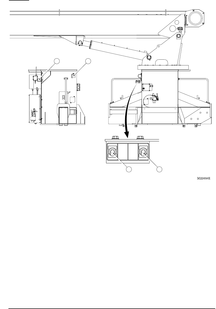
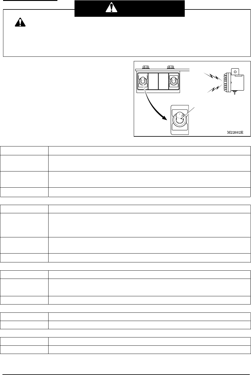
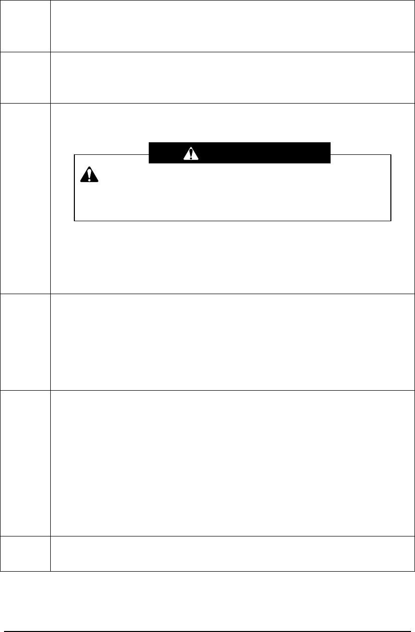
2. If the Radio-control is not Possible
1. The unloading solenoid of the radio-control
valve should be fastened so that the crane
can be manually stowed.
(1) Remove the cap nut.
(2) Loosen the lock nut and lightly tighten the
screw inside until it cannot be turned any
longer.
Fastening the screw too tight may cause
operation failures. Make sure to lightly
tighten the screw.
2. After manually stowing the crane, have the
crane and radio-control system
inspected/repaired at the nearest TADANO
distributor or dealer.
This is a measure to stow the crane in an emergency case. Do not
make any crane operation.
Warning
Cap nut
Lock nut
Screw

M038010E
Troubleshooting Guide 23 Troubleshooting Guide
Troubleshooting Guide
First check the following when a problem occurs during the radio-control operation.
Trouble Checkpoints Measures
Power LED does not
light up.
・ Are batteries inserted?
・ Are batteries inserted in the
correct manner?
・
Are batteries exhausted?
・ Insert batteries.
・ Insert batteries in the
correct manner.
・
Replace batteries.
Power LED flashes. ・
Are batteries exhausted? ・
Replace batteries
After the power is
turned on, four LEDs
flash.
・ Was the power turned on while
the switch on the transmitter
was operated?
・ Was the power turned on while
the speed control lever was
pulled?
・ After releasing your finger
from the switch, turn on
the power.
・ After releasing your finger
from the speed control
lever, turn on the power.
The power of the
transmitter
spontaneously turned
off.
・ When no operation is made for
approximately one hour, the
power of the transmitter is
automatically turned off to save
battery consumption.
・ Turn on the power again.
The power is turned off
during the radio-control
operation.
・ When the motion selection
switch is under operational
state continuously for
approximately five minutes,
transmission from the
transmitter is automatically cut
off to prevent accidents.
・ After confirming that the
motion selection switches
are retuned to the neutral
positions, turn on the
power again.
The accelerator cannot
be revved up.
・ Is the low-speed mode (with
the speed mode LED lighting in
red) selected?
・ Change to the
medium-speed or
high-speed mode.
Batteries are
exhausted in a short
time
・ Battery longevity is shortened
under the conditions with
extremely cold temperatures.
・ Replace batteries.
The crane stops with
two-tone sound.
・ Are cables of the reception unit
or control unit loose?
・ Is the crane used in the
situation as shown on the next
page?
・ Connect the cable
properly.
・ Refer to the next page.
M038010E
Troubleshooting Guide 24 Troubleshooting Guide
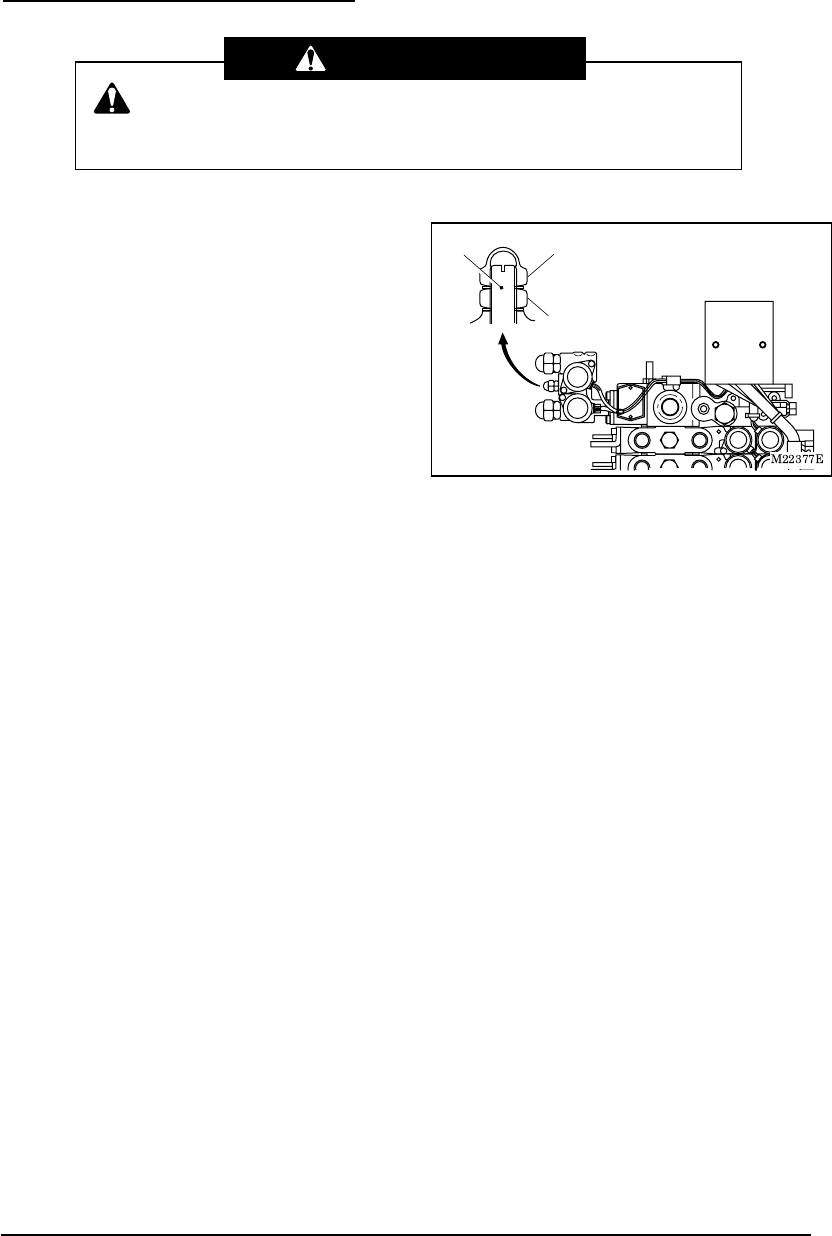
Radio wave transmission is hindered under the following conditions, which may stop the
crane operation. Take an appropriate measure according to the operational condition.
If the appropriate measure does not improve the situation, use the manual operation.
Operation example Appropriate measure
Distance between the transmitter and
reception unit is too far.
・ Too large a distance between the
transmitter and reception unit may not
only hinder the radio wave transmission
but also increase noise influences.
Normally, make the operations within the
operating radius of the crane.
Operation is made near the noise-generating
source.
M00247
・ When a noise generating device such as
a revolving light, electric fan or vehicle’s
air conditioner is used nearby, the
radio-control operation is influenced by
the source.
Turn off the noise-generating device
when it is possible to refrain from using it.
Since a motorcycle also generates a
noise, pay attention to motorcycles
passing through.
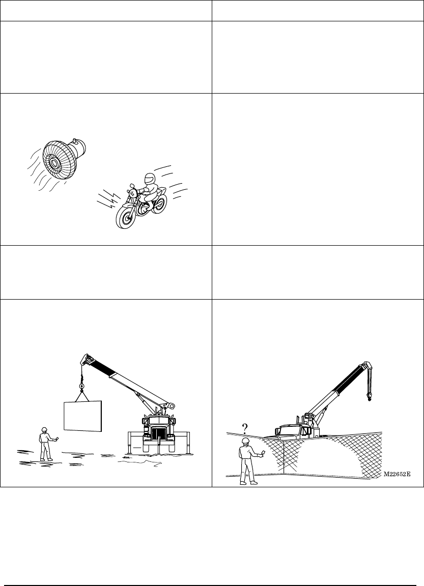
Operation is made in a place with an
intensive radio wave interference causing
noise to the radios and to television screens.
・ Approach the transmitter to the reception
unit and operate the transmitter.
A large metal cargo is lifted with the crane.
Or, there are obstacles between the
transmitter and reception unit such as wire
netting or metal doors.
M22678
?
・ Metal products between the transmitter
and reception unit hinder the radio wave
transmission. Move yourself to the
location where the reception unit can be
seen and then operate the transmitter.
(Wire netting)
M038020E
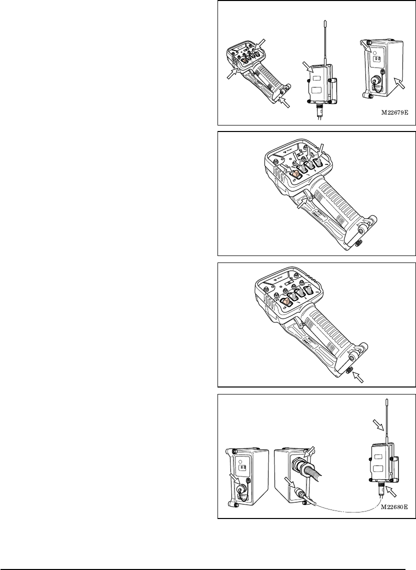
Daily Inspection 25 Daily Inspection
Daily Inspection
Inspect the radio-control system at the time of the pre-operational inspection of the main
unit of the crane.
(1) Is the case of the transmitter or control
unit damaged? Do switches or rubber
parts of the transmitter have any crack
or flaw?
Any damage on the case or any crack or
flaw on the rubber parts may allow water
or dust to enter inside, causing electronic
circuit problems or malfunction of the
crane.
(2) Do the motion selection switches and
speed control lever move smoothly?
Adhered dust or dirt may give unfavorable
impact on operations of the motion
selection switches or speed control lever,
causing operation failures or malfunctions
of the crane.
(3) Is the fixing screw of the transmitter’s
battery cover securely tightened?
A loose fixing screw of the transmitter’s
battery cover may allow water or dust to
enter inside, causing electronic circuit
problems or malfunction of the crane.
(4) Is the cable between the control unit
and communication unit loose or
damaged?
Is the antenna of the communication
unit damaged or loose?
If the connector of the cable or antenna is
loose, a radio wave reaching distance
may be reduced or the radio-control
system may be subject to noises.
In addition, if the cable or antenna is
damaged, the radio-control system may
be subject to noises.
M22681
M22682
Transmitter Communication unit Control unit
26
MEMO

H000781E
TADANO LTD.
Head Office
Ko-34, Sinden-cho, Takamatsu, Japan
Overseas Service Dept.
Tadano Ryogoku Bldg.
4-12, Kamezawa 2-chome,
Sumida-ku,
Tokyo, Japan
Tel. 81-3-3621-7765
Tel fax 81-3-3621-7785
TADANO AMERICA CORP.
333 Northpark Central Drive, SuiteZ,
Houston Texas, 77073 U.S.A.
Tel. 1-281-869-0030
Fax 1-281-869-0040
History of Revision
1
2
3
4
5
