Tagmaster XTMEX RFID Reader User Manual 13 111 P11E XT Series Reader Manual EN
Tagmaster AB RFID Reader 13 111 P11E XT Series Reader Manual EN
UserManual.wiki
>
Tagmaster
>
XTMEX User Manual
User Manual
Navigation menu
Upload a User Manual
Namespaces
Wiki Guide
HTML
PDF
Info
Views
User Manual
Discussion / Help
Navigation

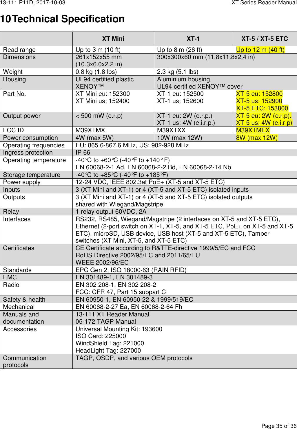
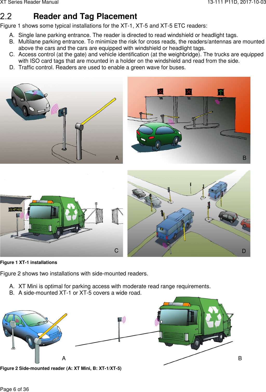
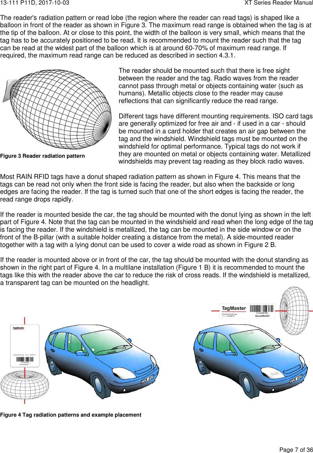
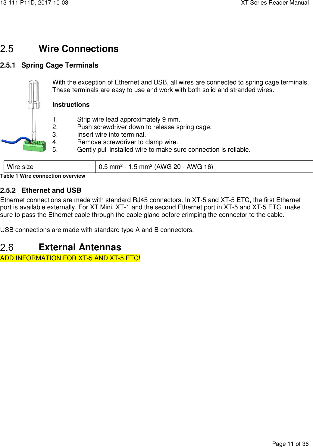
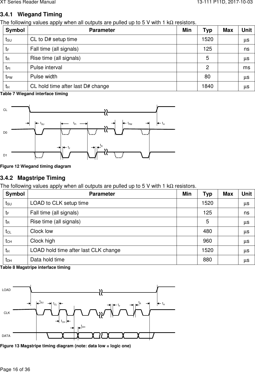
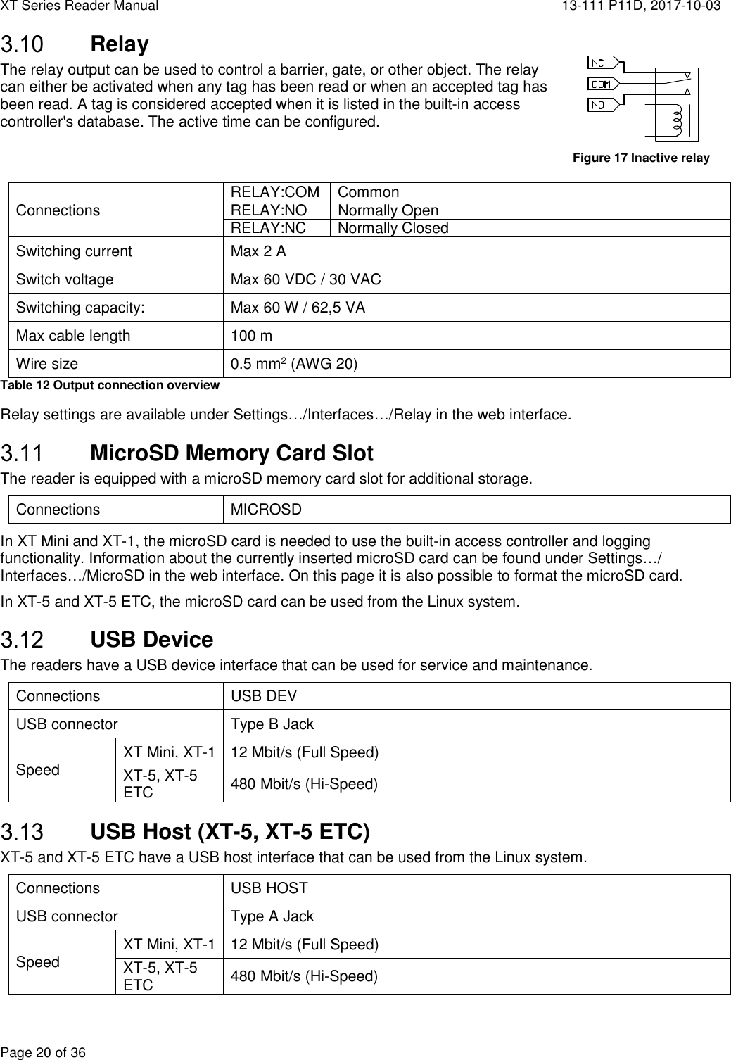
![13-111 P11D, 2017-10-03 XT Series Reader Manual Page 5 of 36 1 Introduction Readers XT Mini, XT-1, XT-5 and XT-5 ETC are RAIN RFID readers that are compliant with EPC Gen 2 and ISO 18000-63. XT Mini and XT-1 has a single integrated antenna. XT-5 has one integrated antenna and support for one external antenna. XT-5 ETC supports up to four external antennas. The readers are tailored for automatic vehicle identification applications such as parking, gated communities, and road tolls. As such, the readers are designed for outdoor use and support a large number of interfaces and protocols. RAIN RFID readers operate in the 860-960 MHz UHF frequency range. To support varying global regulations, the readers come in two versions: EU that operates in the 865-868 MHz range and US that operates in the 902-928 MHz range. Both versions can be configured to work in multiple regions within the respective frequency band. While XT Mini and XT-1 have fixed firmware, XT-5 and XT-5 ETC have a user-programmable Linux system. See "XT-5 / XT-5 ETC Developers Manual" [1] for more information. Tags RAIN RFID tags are typically passive, which means that they are powered by the reader's electromagnetic field instead of having a battery. TagMaster's XT readers support all RAIN RFID tags. Specifically, the readers support the SecureMarkID® tags developed by TagMaster to ensure that each tag has a truly unique identity that is difficult to clone. SecureMarkID® RAIN RFID was originally not developed for access control and therefore has a few weaknesses in these applications. Even if all modern tags have a unique ID, this is often too long for existing access control systems and tags cannot be bought with the IDs in sequence. User-programmed tags can often be cloned by anybody with access to a RAIN RFID reader. To address this issue, TagMaster has developed the SecureMarkID® format that uses an encryption algorithm and non-writeable parts of the tags to create a unique 9-digit ID that works well with access control systems, can be bought in sequence, and is difficult to clone. It is recommend to only use SecureMarkID® tags with the reader. 2 Installation Safety Instructions The following safety instructions should be observed during installation, normal use, and service. Installation and service should only be done by qualified personnel. Shields of cables should be connected to safety ground. The reader must be disconnected from all voltage sources before any installation or service work. Capacitors inside the reader can hold their charge even if the equipment has been disconnected from all voltage sources. Do not modify any part of the product. Repair is to be performed by TagMaster only. Where local regulations exist, these are to be followed. The safety information in this manual is a supplement to local regulations. It is the responsibility of the local project manager to make certain that local regulations are known and followed.](https://usermanual.wiki/Tagmaster/XTMEX/User-Guide-4000968-Page-5.png)
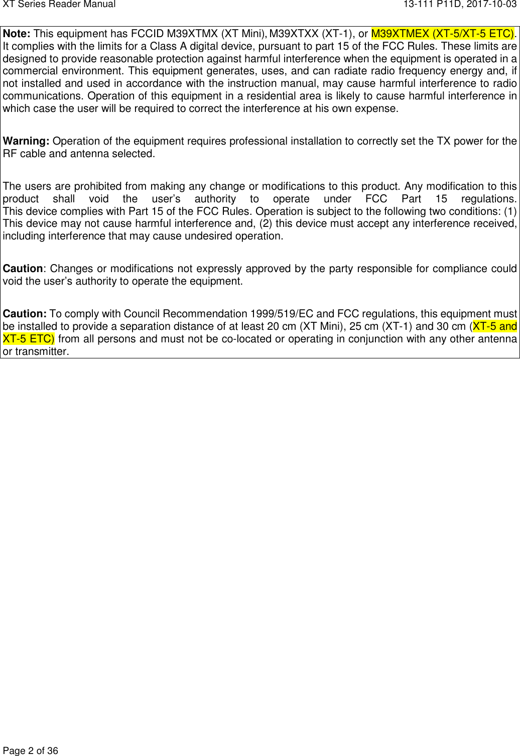
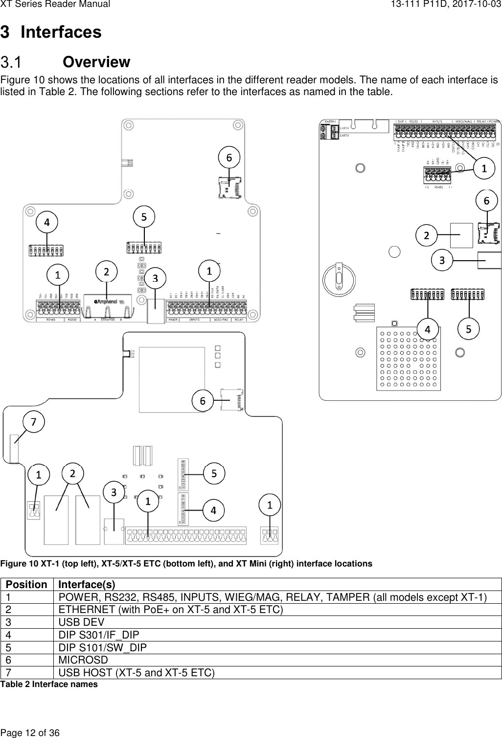
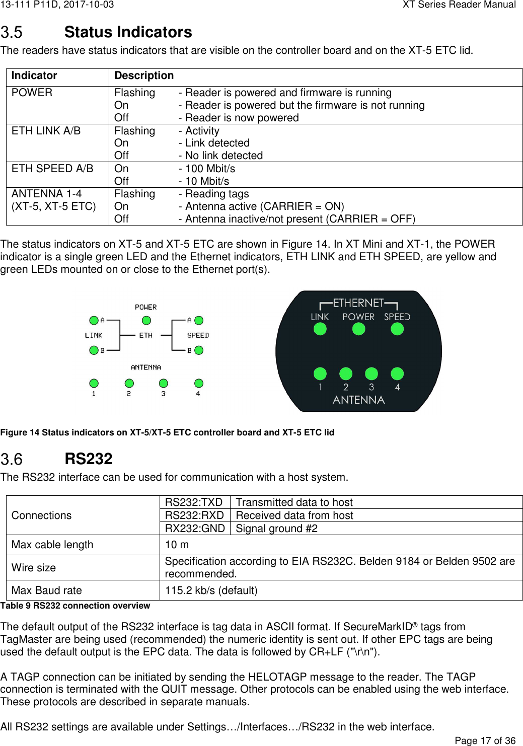
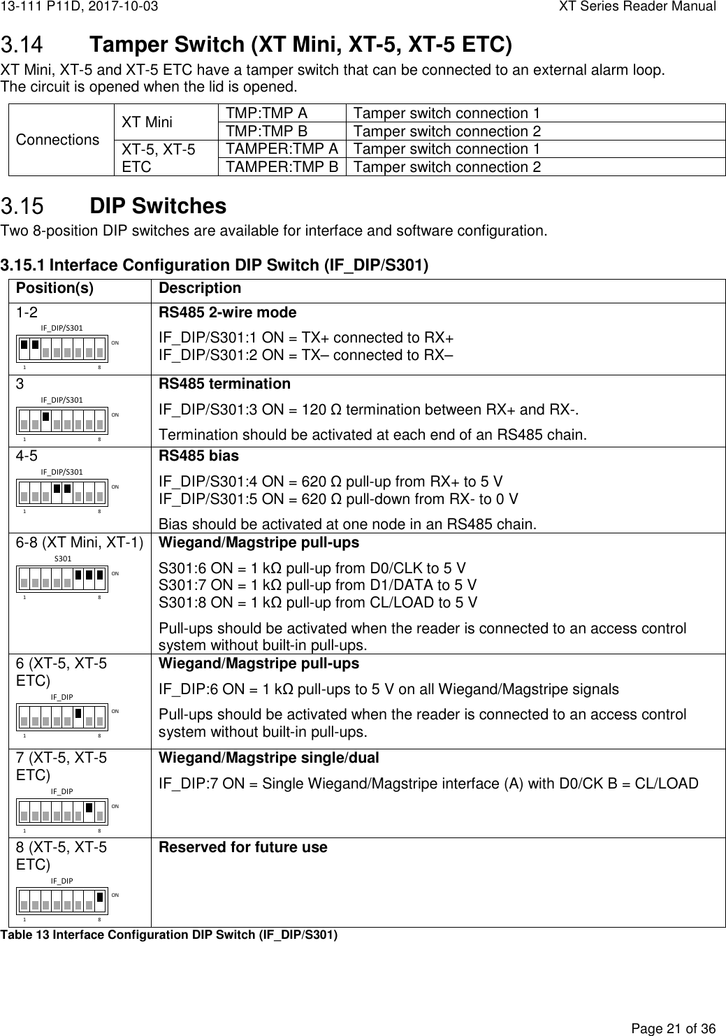
![XT Series Reader Manual 13-111 P11D, 2017-10-03 Page 8 of 36 Mounting Instructions Mount the reader in a horizontal position with the cable glands down. Study the installation examples and radiation patterns in section 2.2 to determine the optimal placement of readers and tags in your installation. 2.3.1 Universal Mounting Kit (UMK) The UMK (TagMaster part. no. 193600) makes it easy to mount the reader in a wide variety of positions and angles. The kit contains all parts needed to mount the reader on a wall or a pole. The kit is designed and suitable for outdoor use. See separate datasheet [1] for more details in on installation. 2.3.2 Dimensions Reader dimensions are shown in Figure 6 (XT-1/XT-5/XT-5 ETC to the left, XT Mini to the right). Figure 6 Reader Dimensions in [inch] and mm Figure 5 Universal Mounting Kit (UMK)](https://usermanual.wiki/Tagmaster/XTMEX/User-Guide-4000968-Page-8.png)
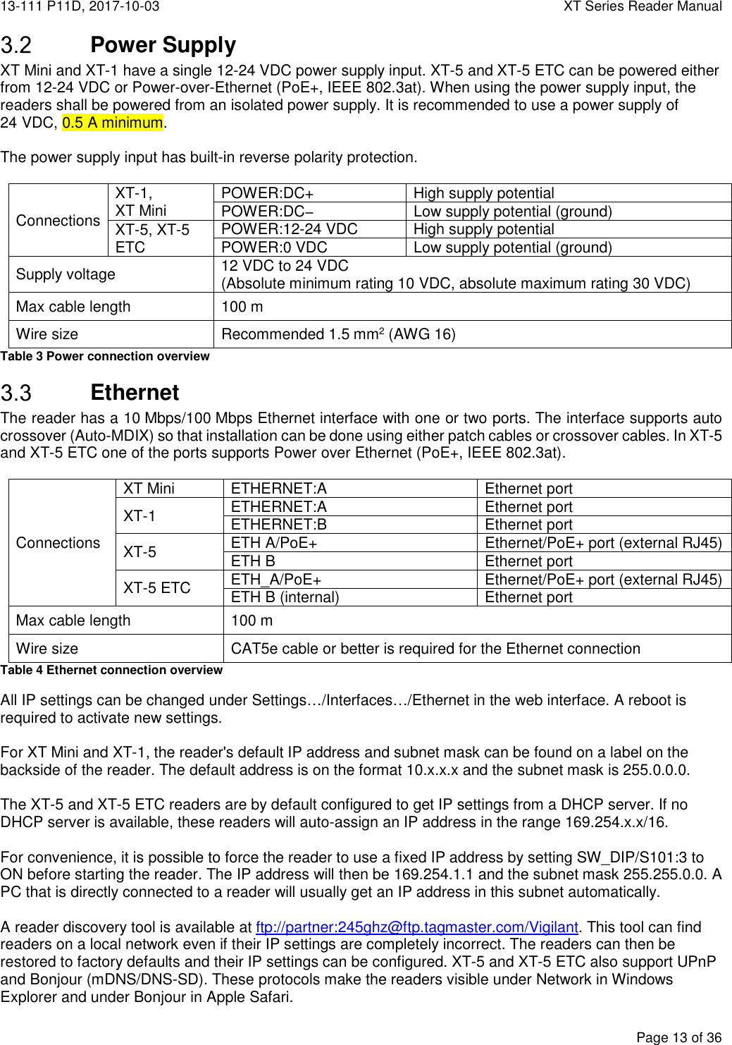
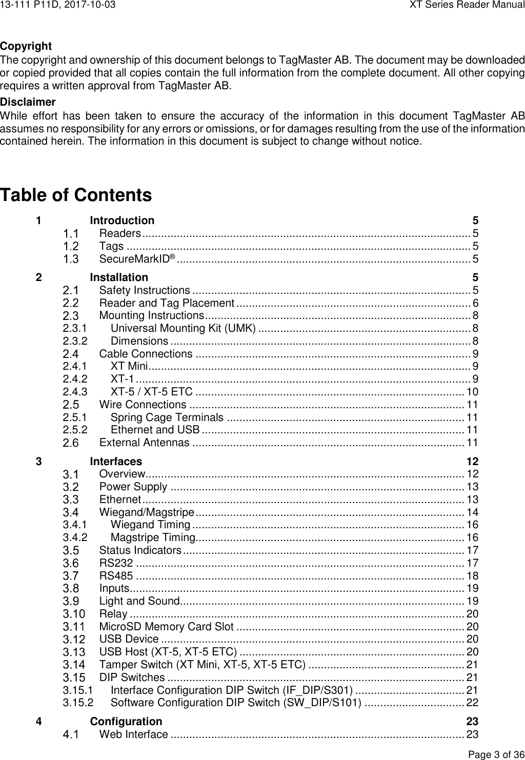
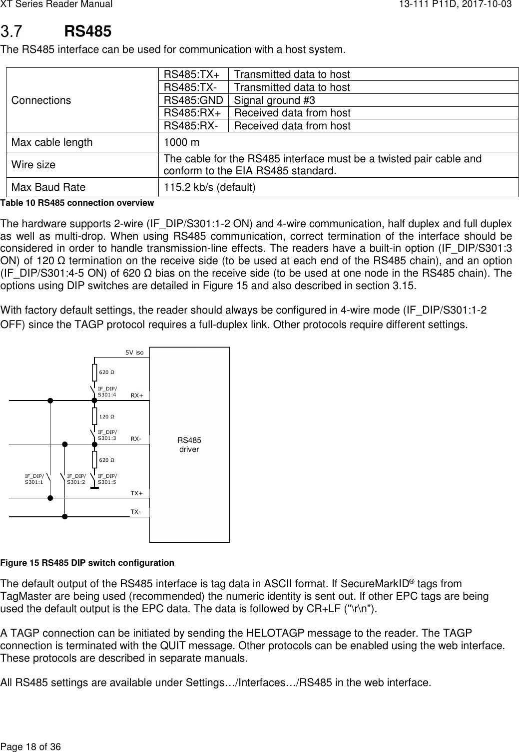
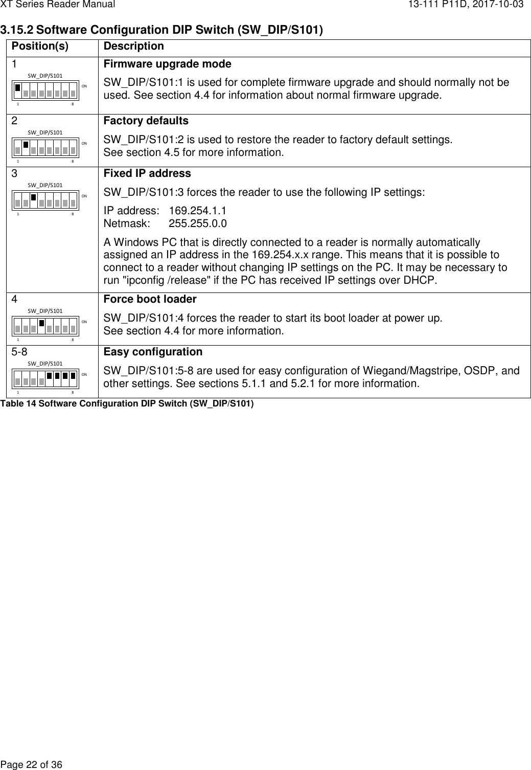
![13-111 P11D, 2017-10-03 XT Series Reader Manual Page 15 of 36 The Wiegand/Magstripe signals can be internally pulled up to 5 V with 1 kΩ resistors. Pull-ups are activated using DIP switches S301:6-8 on XT Mini and XT-1 and IF_DIP:6 on XT-5 and XT-5 ETC. All Wiegand/Magstripe settings are available under Settings…/Interfaces…/Wieg/Mag in the web interface. It is possible to select a predefined format or define a custom format. The most common predefined formats can be selected by setting SW_DIP/S101:5-8 as shown in the table below. When any of these switches are in the ON position, the reader is also configured to report tags once and only accept SecureMarkID tags. The following formats can be selected by DIP switches: D = Data from tag (bit for Wiegand/digit for Magstripe) S = Value of Site code E = Even parity bit, O = Odd parity bit, X = Bit included in parity calculation B = Magstripe start character, F = Magstripe stop character, L = Magstripe LRC Output Format Description W26S/H10301 26-bit Wiegand (8-bit site code, 16-bit data): ESSSSSSSSDDDDDDDDDDDDDDDDO XXXXXXXXXXXXX------------- -------------XXXXXXXXXXXXX W26N/H10301 26-bit Wiegand (24-bit data, no site code): EDDDDDDDDDDDDDDDDDDDDDDDDO XXXXXXXXXXXXX------------- -------------XXXXXXXXXXXXX W34N 34-bit Wiegand (32-bit data, no site code): EDDDDDDDDDDDDDDDDDDDDDDDDDDDDDDDDO XXXXXXXXXXXXXXXXX----------------- -----------------XXXXXXXXXXXXXXXXX W37N/H10302 37-bit Wiegand (35-bit data, no site code): EDDDDDDDDDDDDDDDDDDDDDDDDDDDDDDDDDDDO XXXXXXXXXXXXXXXXXXX------------------ ------------------XXXXXXXXXXXXXXXXXXX W37R/H10302 37-bit Wiegand (37-bit data, no site code, no parity): DDDDDDDDDDDDDDDDDDDDDDDDDDDDDDDDDDDDD M8N/H10320 8-digit Magstripe: [25 zeroes]BDDDDDDDDFL[165 zeroes] Table 6 Wiegand/Magstripe formats 1 8ONSW_DIP/S1011 8ONSW_DIP/S1011 8ONSW_DIP/S1011 8ONSW_DIP/S1011 8ONSW_DIP/S1011 8ONSW_DIP/S101](https://usermanual.wiki/Tagmaster/XTMEX/User-Guide-4000968-Page-15.png)
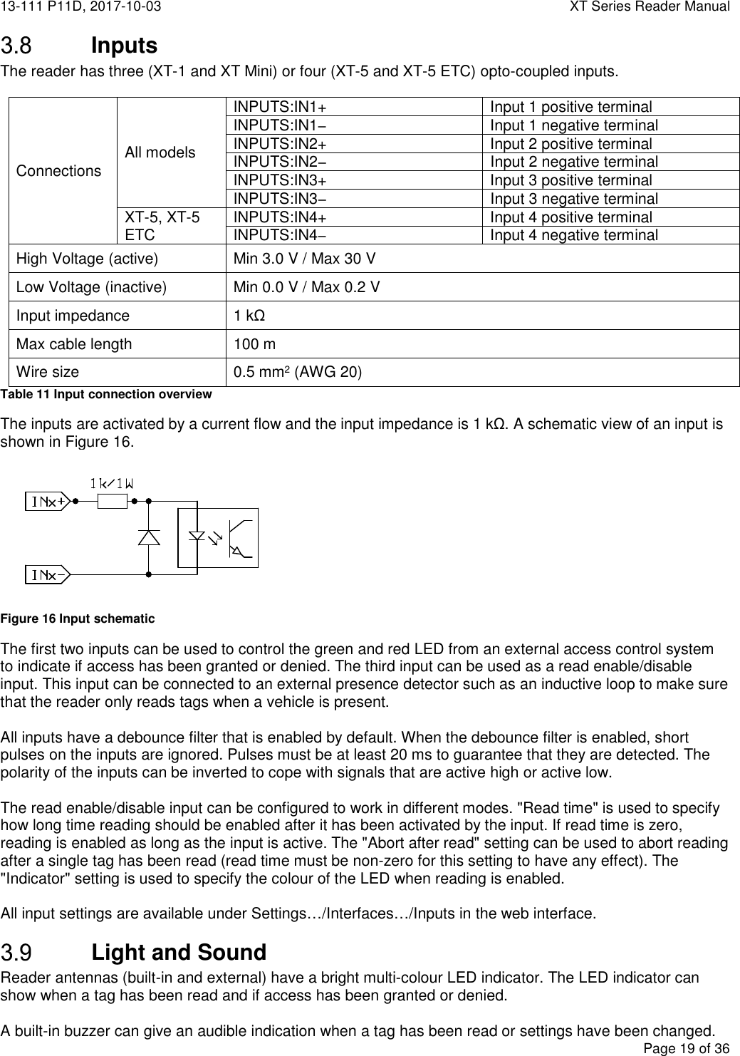
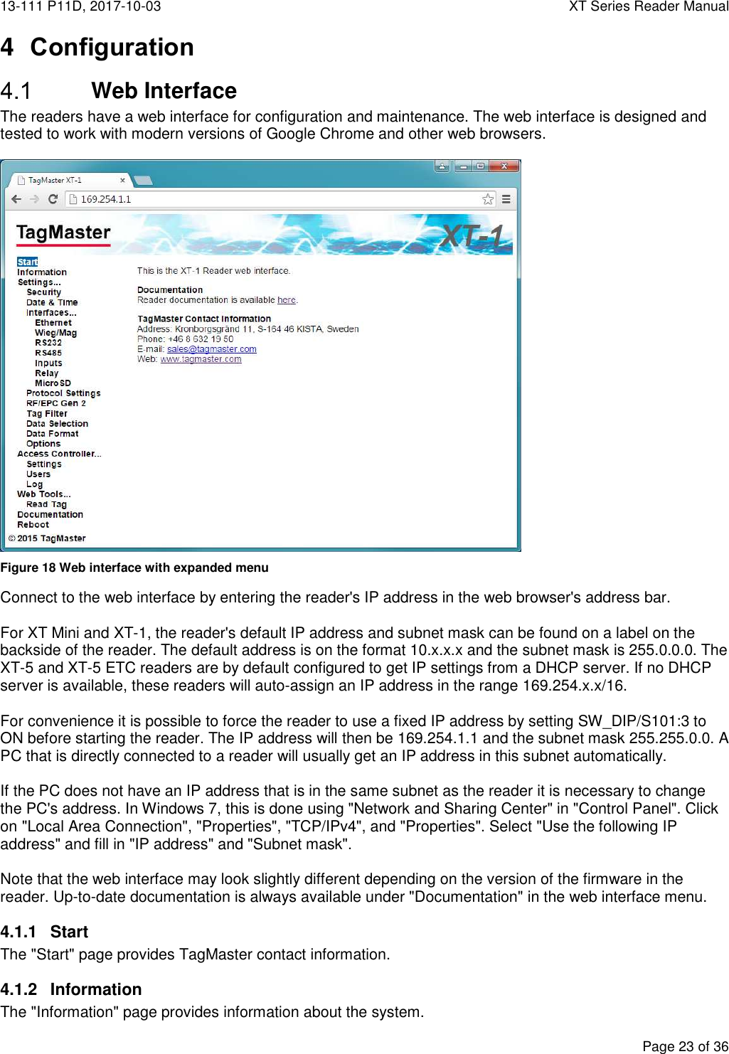
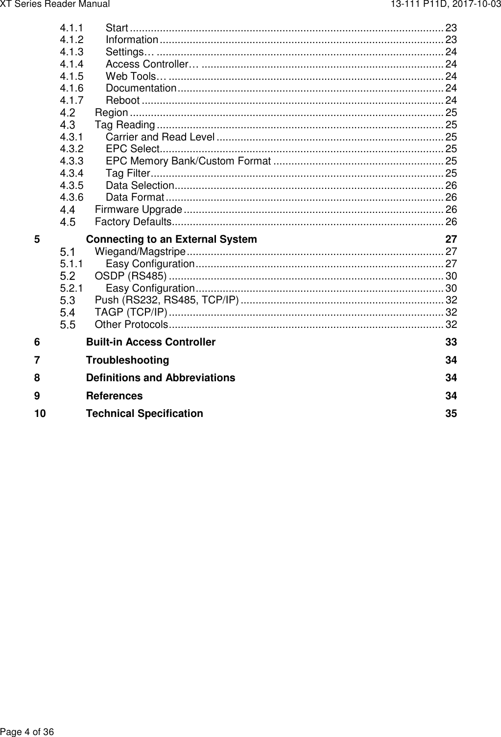
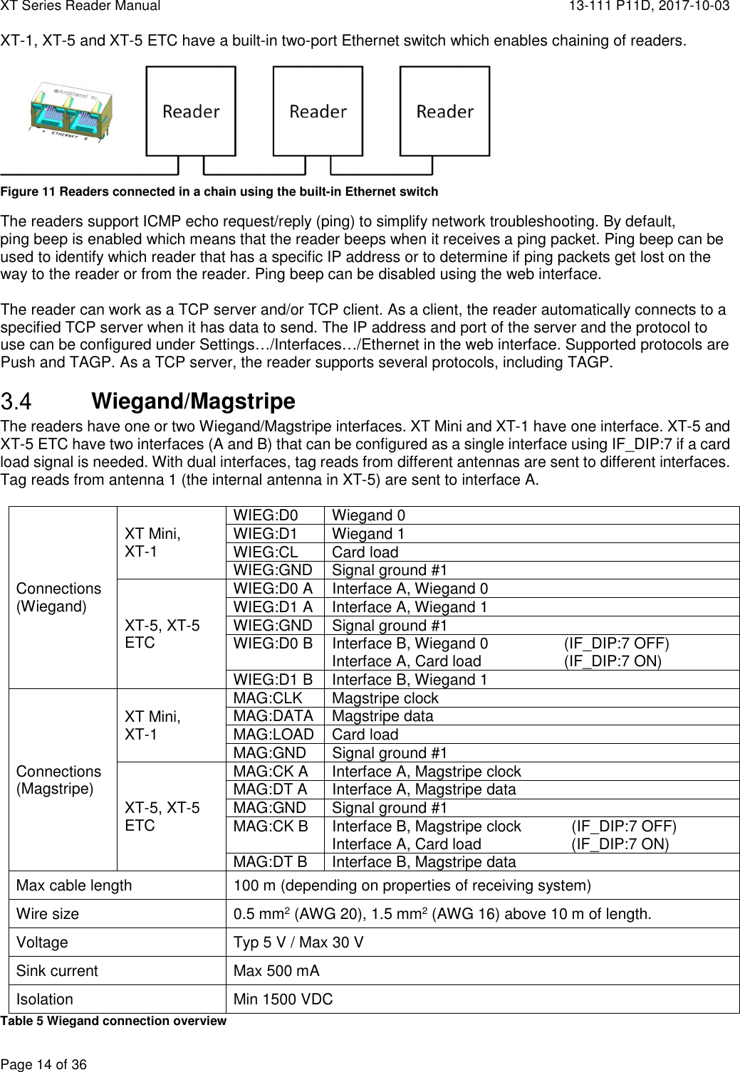
![13-111 P11D, 2017-10-03 XT Series Reader Manual Page 27 of 36 5 Connecting to an External System The following sections describe how to connect the reader to another system. Note that the reader requires more power than a typical proximity reader and should have its own power supply. Wiegand/Magstripe The reader can be connected to a typical access control system using Wiegand/Magstripe. The access control system can control the reader's LED indicator using inputs IN1 and IN2. Input IN3 can be connected to a presence detector such as an inductive loop. An overview is shown in Figure 22. Figure 22 Reader connected to access control system using Wiegand/Magstripe For common access control systems, the reader can be configured using DIP switches as described in section 5.1.1, "Easy Configuration", below. For other systems, all Wiegand/Magstripe settings are available under Settings…/Interfaces…/Wieg/Mag in the web interface. 5.1.1 Easy Configuration The reader can be configured to work with common access control systems using SW_DIP/S101:5-8. When any of these switches are in the ON position, the reader is configured to report tags once, accept SecureMarkID tags only, and use the specified Wiegand/Magstripe format. The following sections describe how to connect the reader to different access control systems and how to set the reader's DIP switches. The following format is used to describe cable connections: [READER SIGNAL] [ACCESS CONTROL SYSTEM SIGNAL] ASSA ARX/RX WEB (with 500RW22) Configure the ARX/RX WEB system to use card type Wiegand. GND 0V IN1+ 12V CL/LOAD N/C IN1- LED_GREEN D0/CLK D0 IN2+ 12V D1/DATA D1 IN2- LED_RED SW_DIP/S101 - Wiegand format: W34N IF_DIP/S301 - Vigilant pull-ups disabled Tested version: RX WEB PR300233 build-8418 version-17.2.0.5 GNDCL/LOADD0/CLKD1/DATAIN1+IN1-IN2+IN2-Wiegand/MagstripeGreen LEDRed LEDIN3+IN3- Presence loopVigilant ReaderAccess Control SystemLoop Controller1 8ONSW_DIP/S1011 8ONIF_DIP1 8ONS301](https://usermanual.wiki/Tagmaster/XTMEX/User-Guide-4000968-Page-27.png)
![XT Series Reader Manual 13-111 P11D, 2017-10-03 Page 28 of 36 AXIS A1001 Configure A1001 to use reader protocol Wiegand with "Dual LED" and set the card format to H10302. GND [READER I/O] - IN1+ [READER I/O] 12V CL/LOAD N/C IN1- [READER I/O] IO5 D0/CLK [READER DATA] D0 IN2+ [READER I/O] 12V D1/DATA [READER DATA] D1 IN2- [READER I/O] IO4 SW_DIP/S101 - Wiegand format: W37N/H10302 IF_DIP/S301 - Vigilant pull-ups enabled Tested version: Firmware version 1.30.0 Bewator Entro Configure the Bewator Entro system to use H10302 format. GND 0V IN1+ N/C CL/LOAD N/C IN1- N/C D0/CLK D0/CLK IN2+ N/C D1/DATA D1/DATA IN2- N/C SW_DIP/S101 IF_DIP/S301 - Vigilant pull-ups disabled Bewator Entro ≥ 6.5: Wiegand format: W37N/H10302 Older versions: Wiegand format: W37R/H10302 Tested version: Bewator Entro 6.55.011 Bewator Omnis (with E2V) The Vigilant reader behaves as a RB500 reader in Clock&Data mode. GND [Conn. G] - IN1+ [Conn. G] +12V CL/LOAD [Conn. E] A IN1- [Conn. G] G D0/CLK [Conn. E] B IN2+ [Conn. G] +12V D1/DATA [Conn. E] C IN2- [Conn. E] R SW_DIP/S101 - Magstripe format: M8N/H10320 IF_DIP/S301 - Vigilant pull-ups enabled Tested version: Bewator Omnis 6.0.107 1 8ONSW_DIP/S1011 8ONIF_DIP1 8ONS3011 8ONIF_DIP1 8ONS3011 8ONSW_DIP/S1011 8ONSW_DIP/S1011 8ONSW_DIP/S1011 8ONIF_DIP1 8ONS301](https://usermanual.wiki/Tagmaster/XTMEX/User-Guide-4000968-Page-28.png)
![13-111 P11D, 2017-10-03 XT Series Reader Manual Page 29 of 36 Paxton Net2 Plus Configure the Paxton system to use reader type "Clock & Data". GND 0V IN1+ 12V CL/LOAD N/C IN1- Green LED D0/CLK Clock/D1 IN2+ 12V D1/DATA Data/D0 IN2- Red LED SW_DIP/S101 - Magstripe format: M8N/H10320 IF_DIP/S301 - Vigilant pull-ups disabled Tested version: Net2 Lite version 4.28.8417 RCO R-CARD M5 (with DB-50W) The RCO system automatically detects the Wiegand format. GND DC- IN1+ N/C CL/LOAD N/C IN1- N/C D0/CLK DATA0 IN2+ N/C D1/DATA DATA1 IN2- N/C SW_DIP/S101 IF_DIP/S301 - Vigilant pull-ups enabled Strap at P14*: Wiegand format: W34N No strap at P14: Wiegand format: W26S/H10302 * To get all digits from the SecureMarkID tag, it is necessary to solder a strap at P14 on the RCO DB-50W board. Without this strap it is only possible to get the last four digits from the tag. Vanderbilt Aliro On the circuit board in the access point, set the EOL jumper for the reader to OFF. In the Aliro software, set reader type to "Wiegand" and card format to "H10302_37". Configure Output_1 to "C&D/Wiegand green" and Output_2 to "C&D/Wiegand red". GND [READER n] - IN1+ [READER n] + CL/LOAD N/C IN1- [OUT 1/2 ] 1 D0/CLK [READER n] A IN2+ [READER n] + D1/DATA [READER n] B IN2- [OUT 1/2 ] 2 SW_DIP/S101 - Wiegand format: W37N/H10302 IF_DIP/S301 - Vigilant pull-ups enabled Tested version: Software version 1.0.0.5371, Access point firmware version 1.0.0.2022 1 8ONSW_DIP/S1011 8ONIF_DIP1 8ONS3011 8ONIF_DIP1 8ONS3011 8ONSW_DIP/S1011 8ONSW_DIP/S1011 8ONSW_DIP/S1011 8ONIF_DIP1 8ONS301](https://usermanual.wiki/Tagmaster/XTMEX/User-Guide-4000968-Page-29.png)
![XT Series Reader Manual 13-111 P11D, 2017-10-03 Page 30 of 36 OSDP (RS485) The reader supports the Open Supervised Device Protocol (OSDP) [5] for connection to access control systems. OSDP communicates over 2-wire RS485 and can therefore be used with long cables and does not require extra cables for LED and buzzer control. IF_DIP/S301:1-2 must be set to ON to enable 2-wire mode on the reader. In most cases IF_DIP/S301:3-5 should also be set to ON to enable biasing and termination. Input IN3 can be connected to a presence detector such as an inductive loop. Figure 23 shows a typical connection diagram and the most common settings for SW_DIP/S101 and IF_DIP/S301. Figure 23 Reader connected to access control system using OSDP All OSDP settings are available under Settings…/Protocol Settings…/OSDP. For common access control systems, OSDP can also be enabled using SW_DIP/S101 as described below. 5.2.1 Easy Configuration Default OSDP Mode Set SW_DIP/S101 and IF_DIP/S301 as shown in Figure 23. 5.2.1.1.1 AXIS A1001 In the A1001 software, set the reader protocol to OSDP, RS485 half duplex. Define a new card format with name SecureMarkID and bit length 32. Set the field map like this: Name: CardNr, Range: 1-32, Encoding: BinLE2Int*. RS485:TX+ [READER DATA n] B+ RS485:GND [READER I/O n] - RS485:TX- [READER DATA n] A- Tested version: Firmware version 1.30.0 5.2.1.1.2 Bravida Integra In the Bravida Integra Software: Set the communication protocol for card reader to OSDP. In card reader, define proper card system. Set card data byte order to “MSB”. Set device bus address to 1. RS485:TX+ PL400-3 + RS485:GND - RS485:TX- PL400-4 - Tested version: Integra SW version 7.0, C-NodeG2 FW version 21.70, S-NodeG2 FW version 20.20 Vanderbilt Aliro In the Aliro software, set reader type to "extended OSDP". RS485:TX+ [READER n] A RS485:GND [READER n] - RS485:TX- [READER n] B SW_DIP/S101 - Vanderbilt AR40S-MF emulation IF_DIP/S301 - 2-wire RS485, bias and termination Tested version: Software version 1.0.0.5371, Access point firmware version 1.0.0.2022 TX+TX-GNDRS485ReaderIN3+IN3- Presence loopAccess Control SystemLoop Controller1 8ONSW_DIP/S1011 8ONSW_DIP/S1011 8ONIF_DIP/S3011 8ONIF_DIP/S301](https://usermanual.wiki/Tagmaster/XTMEX/User-Guide-4000968-Page-30.png)
![13-111 P11D, 2017-10-03 XT Series Reader Manual Page 31 of 36 Vanderbilt SiPass integrated - DRI Door Module Set card technology to Siemens OSDP in FLN configuration tool. RS485:TX+ [Aux Serial] Tx + RS485:GND [Aux Serial] GND RS485:TX- [Aux Serial] Rx - SW_DIP/S101 - Vanderbilt AR40S-MF emulation IF_DIP/S301 - 2-wire RS485, bias and termination Tested version: Software SiPass 2.65 SP4, Firmware ADD5100 (DRI) version 3.42; ACC FW 2.65.51 Vanderbilt SiPass integrated - ERI Door Module Set card technology to Siemens OSDP in FLN configuration tool. RS485:TX+ [SRB RS485] + RS485:GND [SRB PWR] 0V RS485:TX- [SRB RS485] - SW_DIP/S101 - Vanderbilt AR40S-MF emulation IF_DIP/S301 - 2-wire RS485, bias and termination Tested version: Software SiPass 2.65 SP4, Firmware ADE5300 (ERI) version 3.38; ACC FW 2.65.51 1 8ONSW_DIP/S1011 8ONSW_DIP/S1011 8ONIF_DIP/S3011 8ONIF_DIP/S301](https://usermanual.wiki/Tagmaster/XTMEX/User-Guide-4000968-Page-31.png)
![XT Series Reader Manual 13-111 P11D, 2017-10-03 Page 32 of 36 Push (RS232, RS485, TCP/IP) When a tag has been read, the reader can automatically push tag data to RS232, RS485 and a specified TCP server. The Push protocol is enabled by default on RS232 and RS485. To push data to a TCP server it is necessary to specify the IP address and TCP port of the server and enable the Push protocol under Settings…/Interfaces…/Ethernet in the web interface. The format of the pushed data can be configured under Settings…/Data Format. The default format is decimal for SecureMarkID tags and hexadecimal for other tags. TAGP (TCP/IP) TagMaster Readers can be controlled and monitored using a protocol called TAGP. The TAGP protocol is human readable and can be used over TCP/IP, RS232 and RS485. A terminal emulation program such as PuTTY is all that is required to interact with TAGP. The "TAGP Protocol Specification" [3] can be downloaded from www.tagmaster.com. Use login name "partner" and password "245ghz". PuTTY TagMaster Edition can be downloaded from ftp://partner:245ghz@ftp.tagmaster.com. All TAGP messages start with a 4-character message identifier and ends with a new line character. To initiate communication with the TAGP server in the reader, a client has to send a HELO message specifying the required TAGP version. The TAGP server replies with a RPLY message: HELOTAGP/2 RPLYHELO00 The client can then send commands to the reader. The most important commands are SET, SETS, GET, and GETS. SET and GET sets and gets the current value of a variable. SETS and GETS sets and gets the stored value of a variable. The stored value is used to initialize the variable at startup. The following example shows how to set the LED to green: SET LED=GREEN RPLYSET 00 The reader sends events to the client when something happens. The following example shows a TAG event that is sent when a tag has been read: EVNTTAG 20140416151015810%00%07'%14l%00%00%00%00%00%00%00 Other Protocols The reader supports a number of OEM protocols, including SKIDATA BLL4 and Kaba BPA/Bedanet. These protocols are documented in separate protocol manuals that can be downloaded from www.tagmaster.com.](https://usermanual.wiki/Tagmaster/XTMEX/User-Guide-4000968-Page-32.png)
![XT Series Reader Manual 13-111 P11D, 2017-10-03 Page 34 of 36 7 Troubleshooting To facilitate troubleshooting, consider the following: Make sure that the reader has correct supply voltage and sufficient current. Check the POWER status indicator as described in section 3.5. If using Ethernet communication, make sure that the network connection is ok. Check the ETH LINK and SPEED status indicators as described in section 3.5. If the IP address has been forgotten or firmware settings have been corrupted the reader can be restored to factory default settings as described in section 4.5. Make sure that working and correctly formatted EPC Gen 2 tags are being used. 8 Definitions and Abbreviations AES Advanced encryption standard ASCII American standard code for information interchange AWG American wire gauge CR Carriage return DES Data encryption standard DIP Dual in-line package EPC Electronic product code FCC Federal communications commission LED Light emitting diode LF Line feed OEM Original equipment manufacturer RFID Radio-frequency identification PC Personal computer SecureMarkID® A TagMaster implementation for improved Security using EPC tags TAGP A TagMaster protocol for RFID reader communication TCP/IP An Internet protocol suite UMK Universal mounting kit USB Universal serial bus 9 References [1] 1117-129 XT-5 / XT-5 ETC DEVELOPER'S MANUAL [2] 06-147 UMK 193600 DATA SHEET [3] 05-172 TAGP PROTOCOL SPECIFICATION [4] EPC GEN 2 SPECIFICATION V.2.0.1, HTTP://WWW.GS1.ORG [5] SIA OPEN SUPERVISED DEVICE PROTOCOL, HTTP://WWW.SIAONLINE.ORG All documentation is available at ftp://partner:245ghz@ftp.tagmaster.com/Documentation.](https://usermanual.wiki/Tagmaster/XTMEX/User-Guide-4000968-Page-34.png)