Tagmaster XTMX RFID Reader User Manual 13 111 05 XT 1 XT Mini Manual EN
Tagmaster AB RFID Reader 13 111 05 XT 1 XT Mini Manual EN
UserManual.wiki
>
Tagmaster
>
XTMX User Manual
User Manual
Navigation menu
Upload a User Manual
Namespaces
Wiki Guide
HTML
PDF
Info
Views
User Manual
Discussion / Help
Navigation

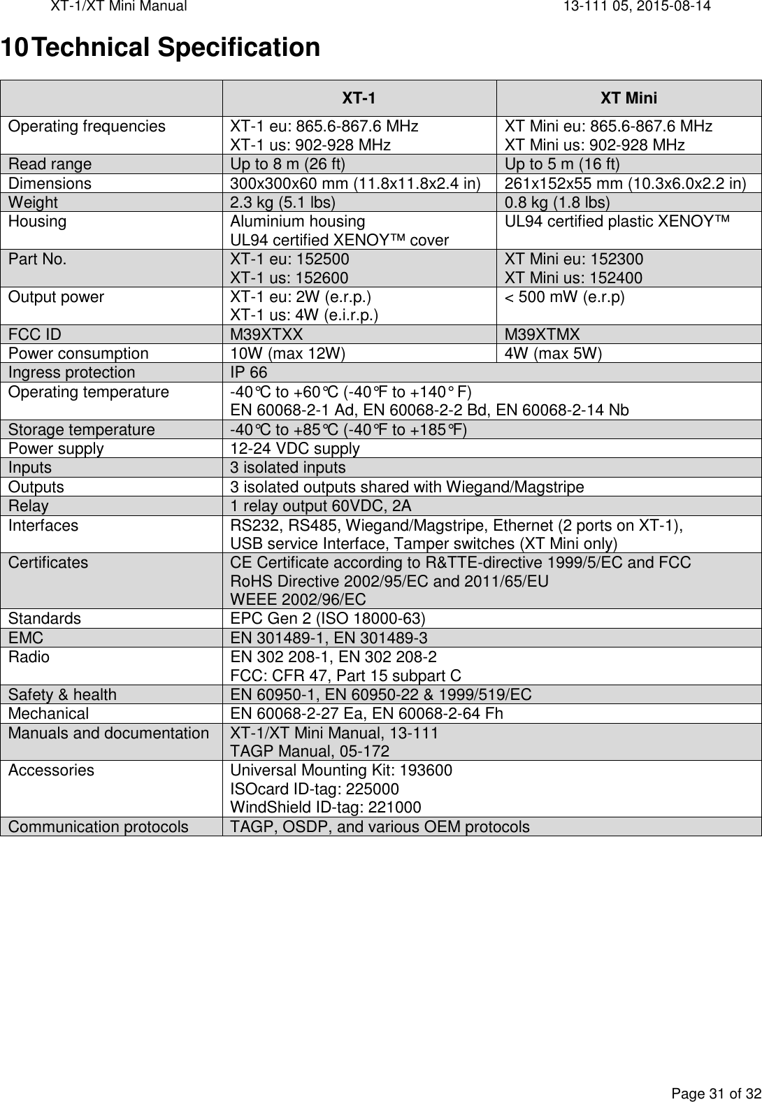
![XT-1/XT Mini Manual 13-111 05, 2015-08-14 Page 8 of 32 Mounting Instructions Mount the reader in a horizontal position with the cable glands down. Study the installation examples and radiation patterns in section 2.2 to determine the optimal placement of readers and tags in your installation. 2.3.1 Universal Mounting Kit (UMK) The UMK (TagMaster part. no. 193600) makes it easy to mount the reader in a wide variety of positions and angles. The kit contains all parts needed to mount the reader on a wall or a pole. The kit is designed and suitable for outdoor use. See separate datasheet [1] for more details in on installation. 2.3.2 Dimensions Reader dimensions are shown in Figure 7 (XT-1 to the left, XT Mini to the right). Figure 7 Reader Dimensions in [inch] and mm Figure 6 Universal Mounting Kit (UMK)](https://usermanual.wiki/Tagmaster/XTMX/User-Guide-2716340-Page-8.png)
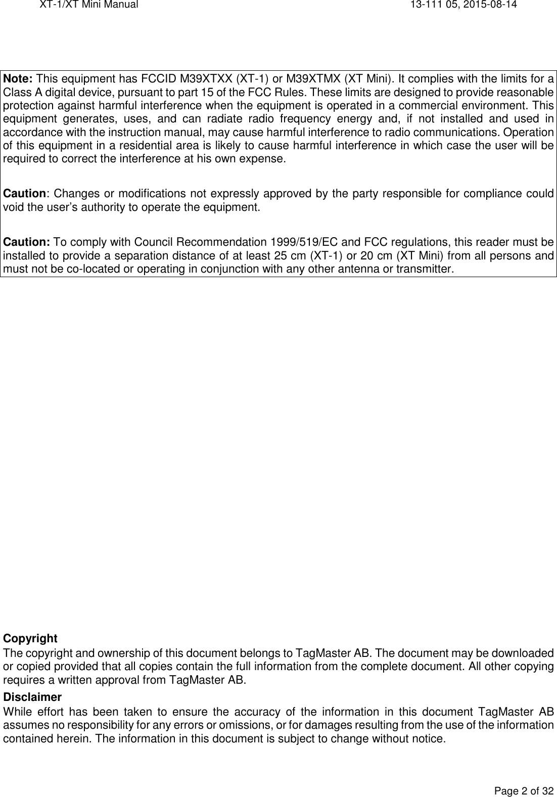
![XT-1/XT Mini Manual 13-111 05, 2015-08-14 Page 13 of 32 W37N/H10302 37-bit Wiegand (35-bit data, no site code): EDDDDDDDDDDDDDDDDDDDDDDDDDDDDDDDDDDDO XXXXXXXXXXXXXXXXXXX------------------ ------------------XXXXXXXXXXXXXXXXXXX W37R/H10302 37-bit Wiegand (37-bit data, no site code, no parity): DDDDDDDDDDDDDDDDDDDDDDDDDDDDDDDDDDDDD M8N/H10320 8-digit Magstripe: [25 zeroes]BDDDDDDDDFL[165 zeroes] Table 5 Wiegand/Magstripe formats Using DIP switches S301:6-8 it is possible to activate 1 kΩ pull-up resistors on D0/CLK, D1/DATA and CL/LOAD. Details are shown in Figure 11. Figure 11 Wiegand/Magstripe DIP switch configuration 3.3.1 Wiegand Timing The following values apply when all outputs are pulled up to 5 V with 1 kΩ resistors. Symbol Parameter Min Typ Max Unit tSU CL to D# setup time 1520 µs tF Fall time (all signals) 125 ns tR Rise time (all signals) 5 µs tPI Pulse interval 2 ms tPW Pulse width 80 µs tH CL hold time after last D# change 1840 µs Table 6 Wiegand interface timing 1 8ONS1011 8ONS1011 8ONS101 S301:6 1kΩ D0/CLK 5V S301:7 1kΩ D1/DATA S301:8 1kΩ CL/LOAD GND](https://usermanual.wiki/Tagmaster/XTMX/User-Guide-2716340-Page-13.png)
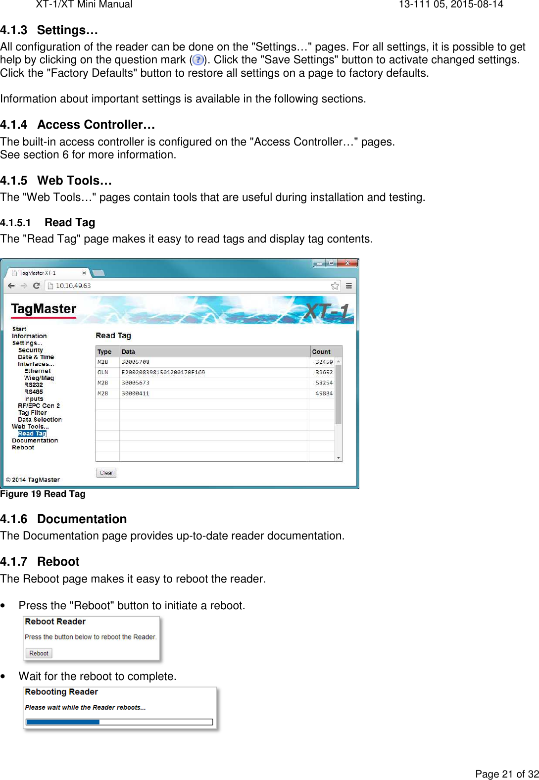
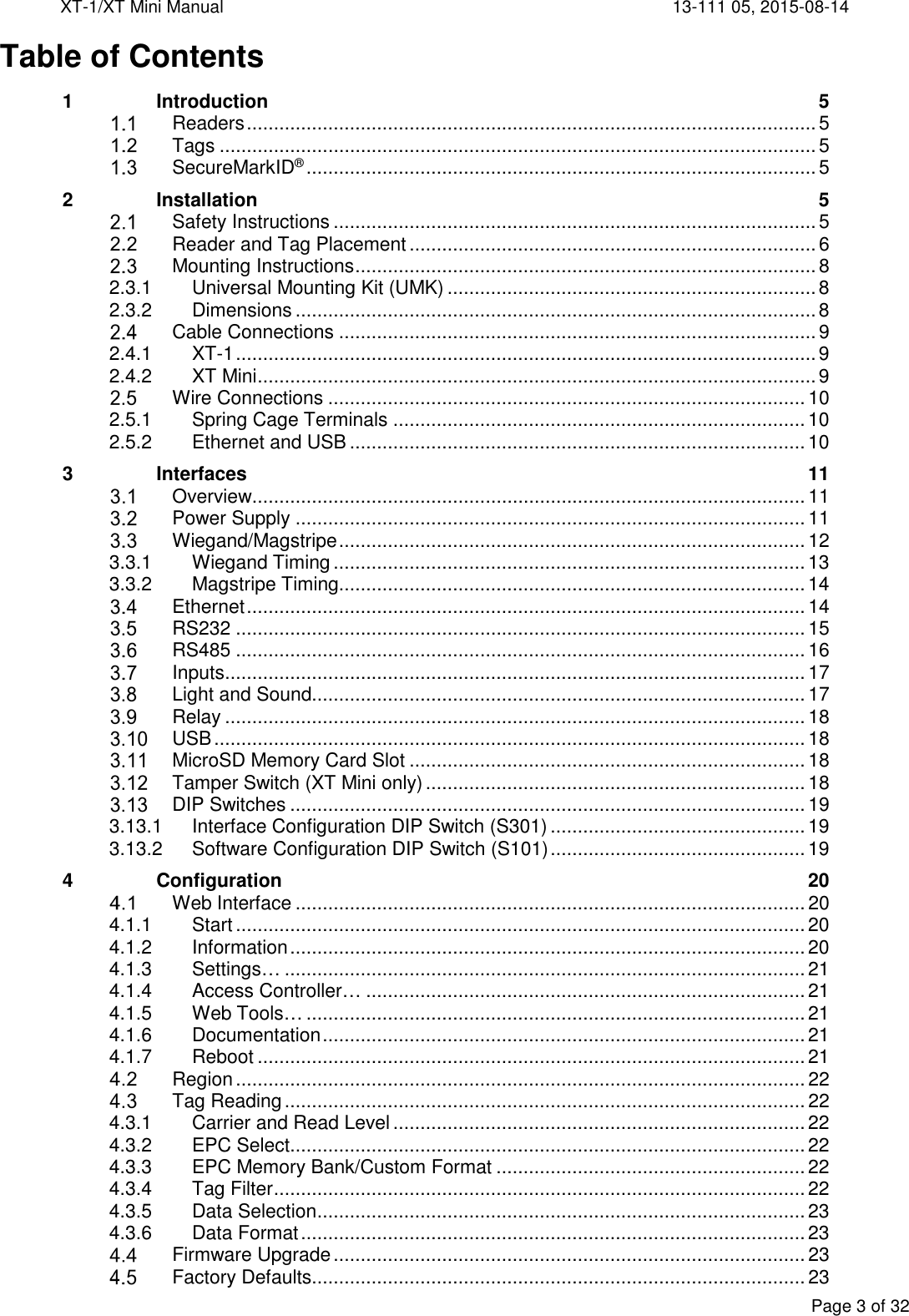
![XT-1/XT Mini Manual 13-111 05, 2015-08-14 Page 22 of 32 Region To meet different radio regulations around the world, the reader can be configured to work in different regions. Each reader model comes in two versions: EU and US. Each reader version supports a number of regions as listed in the table below. Default values are shown in bold. The region can be changed under Settings…/RF/EPC Gen 2 in the web interface. Reader Version Supported Regions EU Europe, India US United States, Australia, China, Malaysia, New Zealand Table 15 Supported regions Tag Reading By default, the reader reads tags with maximum read range and outputs tag data in a way that is suitable for most applications. If necessary, the tag reading process is highly configurable. Most settings controlling tag reading are available under Settings…/RF/EPC Gen 2 in the web interface. The EPC Gen 2 specification [3] mentions three operations on tag populations: select, inventory, and access. The reader automatically performs all of these when the "Carrier" setting is on. The tag reading process is show in Figure 20 and described in the following sections. Figure 20 Reading tags 4.3.1 Carrier and Read Level The "Carrier" setting is used to enable/disable reading. When Carrier is on (default) the reader reads tags. The "Read level" setting controls the read range. The default value 100 corresponds to maximum read range. 4.3.2 EPC Select The "EPC select" setting defines which tags the reader will talk to. Selection is done by specifying a binary value and a part of tag memory that must match the value. Only tags that match will respond to the reader's query. The default value "*" selects all tags. 4.3.3 EPC Memory Bank/Custom Format The settings "EPC memory bank" and "EPC custom format" specifies which parts of the tag memory that will be read by the reader. Available options include EPC/SecureMarkID (default), SecureMarkID, EPC, TID and "Custom Format". If "EPC memory bank" is set to "Custom Format" the "EPC custom format" setting specifies which parts of the tag memory that will be read. 4.3.4 Tag Filter The tag filter (under Settings…/Tag Filter in the web interface) specifies how often tags are reported. Tags can be reported every time they are read, periodically or once. It is also possible to get a tag event when a tag is no longer read by the reader. It is possible to activate read beep and read blink to get an indication every time a tag is reported. EPC Select Tag Filter Data SelectionData FormatEPC MemoryBankTAGP Other ProtocolsPush Protocol(RS232, RS485,TCP Client,Access Controller)](https://usermanual.wiki/Tagmaster/XTMX/User-Guide-2716340-Page-22.png)
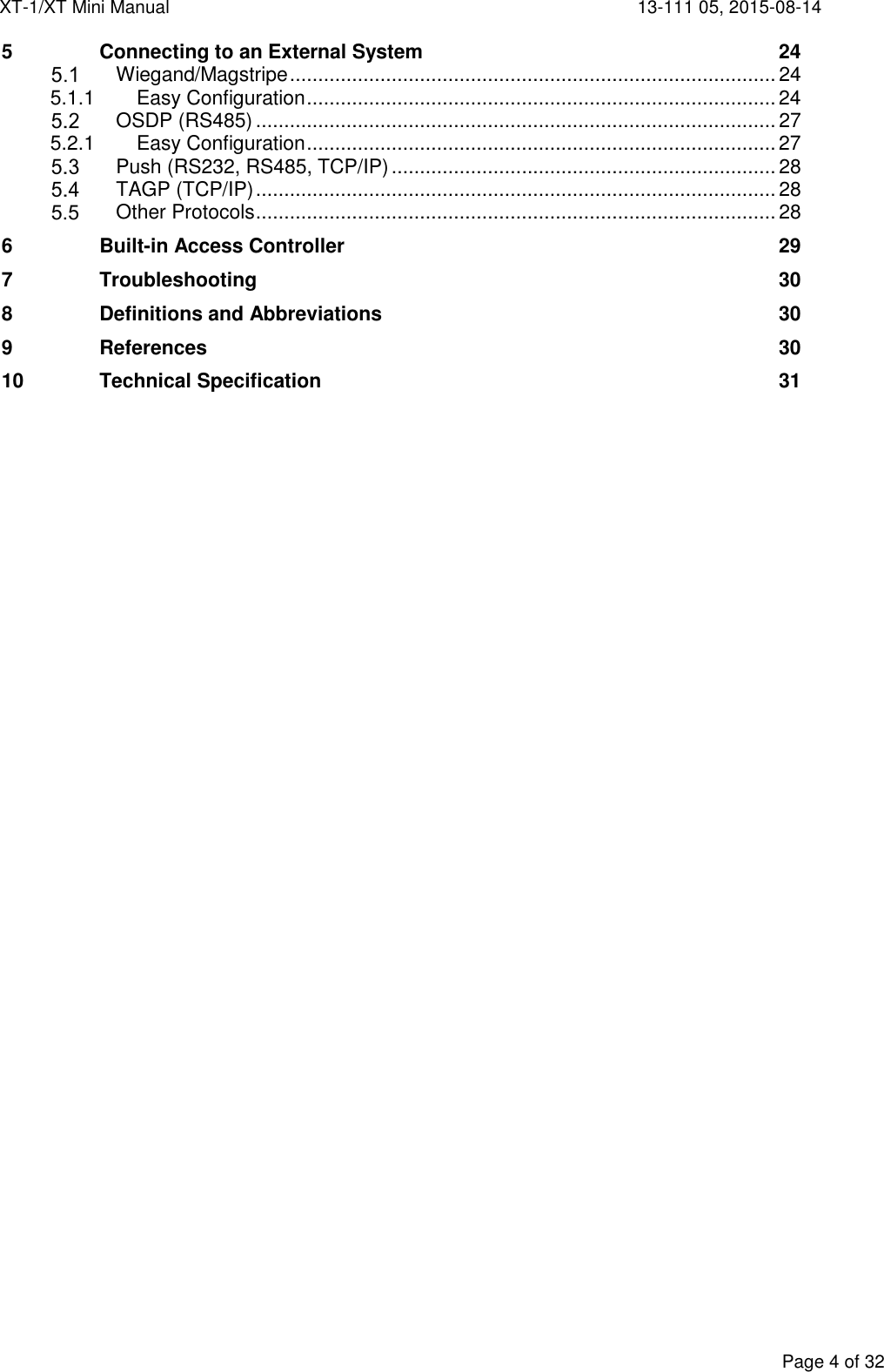
![XT-1/XT Mini Manual 13-111 05, 2015-08-14 Page 24 of 32 5 Connecting to an External System The following sections describe how to connect the reader to another system. Note that the reader requires more power than a typical proximity reader and should have its own power supply. Wiegand/Magstripe The reader can be connected to a typical access control system using Wiegand/Magstripe. The access control system can control the reader's LED indicator using inputs IN1 and IN2. Input IN3 can be connected to a presence detector such as an inductive loop. An overview is shown in Figure 21. Figure 21 Reader connected to access control system using Wiegand/Magstripe For common access control systems, the reader can be configured using DIP switches as described in section 5.1.1, "Easy Configuration", below. For other systems, all Wiegand/Magstripe settings are available under Settings…/Interfaces…/Wieg/Mag in the web interface. 5.1.1 Easy Configuration The reader can be configured to work with common access control systems using DIP switches S101:6-8. When any of these switches are in the ON position, the reader is configured to report tags once, accept SecureMarkID tags only, and use the specified Wiegand/Magstripe format. The following sections describe how to connect the reader to different access control systems and how to set the reader's DIP switches. The following format is used to describe cable connections: [READER SIGNAL] [ACCESS CONTROL SYSTEM SIGNAL] 5.1.1.1 ASSA ARX/RX WEB (with 500RW22) Configure the ARX/RX WEB system to use card type Wiegand. GND 0V IN1+ 12V CL/LOAD N/C IN1- LED_GREEN D0/CLK D0 IN2+ 12V D1/DATA D1 IN2- LED_RED S101 - Wiegand format: W34N S301 - Vigilant pull-ups disabled Tested version: RX WEB PR300233 build-8418 version-17.2.0.5 GNDCL/LOADD0/CLKD1/DATAIN1+IN1-IN2+IN2-Wiegand/MagstripeGreen LEDRed LEDIN3+IN3- Presence loopVigilant ReaderAccess Control SystemLoop Controller1 8ONS1011 8ONS301](https://usermanual.wiki/Tagmaster/XTMX/User-Guide-2716340-Page-24.png)
![XT-1/XT Mini Manual 13-111 05, 2015-08-14 Page 25 of 32 5.1.1.2 AXIS A1001 Configure A1001 to use reader protocol Wiegand with "Dual LED" and set the card format to H10302. GND [READER I/O] - IN1+ [READER I/O] 12V CL/LOAD N/C IN1- [READER I/O] IO5 D0/CLK [READER DATA] D0 IN2+ [READER I/O] 12V D1/DATA [READER DATA] D1 IN2- [READER I/O] IO4 S101 - Wiegand format: W37N/H10302 S301 - Vigilant pull-ups enabled Tested version: Firmware version 1.30.0 5.1.1.3 Bewator Entro Configure the Bewator Entro system to use H10302 format. GND 0V IN1+ N/C CL/LOAD N/C IN1- N/C D0/CLK D0/CLK IN2+ N/C D1/DATA D1/DATA IN2- N/C S101 S301 - Vigilant pull-ups disabled Bewator Entro ≥ 6.5: Wiegand format: W37N/H10302 Older versions: Wiegand format: W37R/H10302 Tested version: Bewator Entro 6.55.011 5.1.1.4 Bewator Omnis (with E2V) The Vigilant reader behaves as a RB500 reader in Clock&Data mode. GND [Conn. G] - IN1+ [Conn. G] +12V CL/LOAD [Conn. E] A IN1- [Conn. G] G D0/CLK [Conn. E] B IN2+ [Conn. G] +12V D1/DATA [Conn. E] C IN2- [Conn. E] R S101 - Magstripe format: M8N/H10320 S301 - Vigilant pull-ups enabled Tested version: Bewator Omnis 6.0.107 1 8ONS1011 8ONS3011 8ONS3011 8ONS1011 8ONS1011 8ONS1011 8ONS301](https://usermanual.wiki/Tagmaster/XTMX/User-Guide-2716340-Page-25.png)
![XT-1/XT Mini Manual 13-111 05, 2015-08-14 Page 26 of 32 5.1.1.5 Paxton Net2 Plus Configure the Paxton system to use reader type "Clock & Data". GND 0V IN1+ 12V CL/LOAD N/C IN1- Green LED D0/CLK Clock/D1 IN2+ 12V D1/DATA Data/D0 IN2- Red LED S101 - Magstripe format: M8N/H10320 S301 - Vigilant pull-ups disabled Tested version: Net2 Lite version 4.28.8417 5.1.1.6 RCO R-CARD M5 (with DB-50W) The RCO system automatically detects the Wiegand format. GND DC- IN1+ N/C CL/LOAD N/C IN1- N/C D0/CLK DATA0 IN2+ N/C D1/DATA DATA1 IN2- N/C S101 S301 - Vigilant pull-ups enabled Strap at P14*: Wiegand format: W34N No strap at P14: Wiegand format: W26S/H10302 * To get all digits from the SecureMarkID tag, it is necessary to solder a strap at P14 on the RCO DB-50W board. Without this strap it is only possible to get the last four digits from the tag. 5.1.1.7 Vanderbilt Aliro On the circuit board in the access point, set the EOL jumper for the reader to OFF. In the Aliro software, set reader type to "Wiegand" and card format to "H10302_37". Configure Output_1 to "C&D/Wiegand green" and Output_2 to "C&D/Wiegand red". GND [READER n] - IN1+ [READER n] + CL/LOAD N/C IN1- [OUT 1/2 ] 1 D0/CLK [READER n] A IN2+ [READER n] + D1/DATA [READER n] B IN2- [OUT 1/2 ] 2 S101 - Wiegand format: W37N/H10302 S301 - Vigilant pull-ups enabled Tested version: Software version 1.0.0.5371, Access point firmware version 1.0.0.2022 1 8ONS1011 8ONS3011 8ONS3011 8ONS1011 8ONS1011 8ONS1011 8ONS301](https://usermanual.wiki/Tagmaster/XTMX/User-Guide-2716340-Page-26.png)
![XT-1/XT Mini Manual 13-111 05, 2015-08-14 Page 27 of 32 OSDP (RS485) The reader supports the Open Supervised Device Protocol (OSDP) [4] for connection to access control systems. OSDP communicates over 2-wire RS485 and can therefore be used with long cables and does not require extra cables for LED and buzzer control. The DIP switch S301:1-2 must be set to ON to enable 2-wire mode on the reader. In most cases S301:3-5 should also be set to ON to enable biasing and termination. Input IN3 can be connected to a presence detector such as an inductive loop. Figure 22 shows a typical connection diagram and the most common setting for DIP switch S301. Figure 22 Reader connected to access control system using OSDP All OSDP settings are available under Settings…/Protocol Settings…/OSDP. For common access control systems, OSDP can also be enabled using DIP switch S101 as described below. 5.2.1 Easy Configuration 5.2.1.1 AXIS A1001 In the A1001 software, set the reader protocol to OSDP, RS485 half duplex. Define a new card format with name SecureMarkID and bit length 28. Set the field map like this: Name: CardNr, Range: 1-28, Encoding: BinLE2Int* RS485:TX+ [READER DATA n] B+ RS485:GND [READER I/O n] - RS485:TX- [READER DATA n] A- S101 - Default OSDP S301 - 2-wire RS485 with bias and termination Tested version: Firmware version 1.30.0 5.2.1.2 Vanderbilt Aliro In the Aliro software, set reader type to "Siemens OSDP". RS485:TX+ [READER n] A RS485:GND [READER n] - RS485:TX- [READER n] B S101 - Aliro emulation mode S301 - 2-wire RS485 with bias and termination Tested version: Software version 1.0.0.5371, Access point firmware version 1.0.0.2022 RS485TX+TX-GNDReaderIN3+IN3- Presence loopAccess Control SystemLoop Controller1 8ONS1011 8ONS3011 8ONS1011 8ONS3011 8ONS301](https://usermanual.wiki/Tagmaster/XTMX/User-Guide-2716340-Page-27.png)
![XT-1/XT Mini Manual 13-111 05, 2015-08-14 Page 28 of 32 Push (RS232, RS485, TCP/IP) When a tag has been read, the reader can automatically push tag data to RS232, RS485 and a specified TCP server. The Push protocol is enabled by default on RS232 and RS485. To push data to a TCP server it is necessary to specify the IP address and TCP port of the server and enable the Push protocol under Settings…/Interfaces…/Ethernet in the web interface. The format of the pushed data can be configured under Settings…/Data Format. The default format is decimal for SecureMarkID tags and hexadecimal for other tags. TAGP (TCP/IP) TagMaster Readers can be controlled and monitored using a protocol called TAGP. The TAGP protocol is human readable and can be used over TCP/IP, RS232 and RS485. A terminal emulation program such as PuTTY is all that is required to interact with TAGP. The "TAGP Protocol Specification" [2] can be downloaded from www.tagmaster.com. Use login name "partner" and password "245ghz". PuTTY TagMaster Edition can be downloaded from ftp://partner:245ghz@ftp.tagmaster.com. All TAGP messages start with a 4-character message identifier and ends with a new line character. To initiate communication with the TAGP server in the reader, a client has to send a HELO message specifying the required TAGP version. The TAGP server replies with a RPLY message: HELOTAGP/2 RPLYHELO00 The client can then send commands to the reader. The most important commands are SET, SETS, GET, and GETS. SET and GET sets and gets the current value of a variable. SETS and GETS sets and gets the stored value of a variable. The stored value is used to initialize the variable at startup. The following example shows how to set the LED to green: SET LED=GREEN RPLYSET 00 The reader sends events to the client when something happens. The following example shows a TAG event that is sent when a tag has been read: EVNTTAG 20140416151015810%00%07'%14l%00%00%00%00%00%00%00 Other Protocols The reader supports a number of OEM protocols, including SKIDATA BLL4 and Kaba BPA/Bedanet. These protocols are documented in separate protocol manuals that can be downloaded from www.tagmaster.com.](https://usermanual.wiki/Tagmaster/XTMX/User-Guide-2716340-Page-28.png)
![XT-1/XT Mini Manual 13-111 05, 2015-08-14 Page 30 of 32 7 Troubleshooting To facilitate troubleshooting, consider the following: Make sure that the reader has correct supply voltage and sufficient current. Check the small green LED on the controller board inside the reader. When the LED is flashing (once per second) the reader is powered and the firmware is running. If the LED is on, but not flashing, the reader is powered but the firmware is not running. If the LED is off, the reader is not powered. If using Ethernet communication, make sure that the network connection is ok. There are small LEDs on or close to the RJ45 socket, only visible when the lid of the reader is open. A yellow light indicates ‘Link’ and a flashing yellow light indicates ‘Activity’. If the IP address has been forgotten or firmware settings have been corrupted the reader can be restored to factory default settings as described in section 4.5. Make sure that working and correctly formatted EPC Gen 2 tags are being used. 8 Definitions and Abbreviations AES Advanced encryption standard ASCII American standard code for information interchange AWG American wire gauge CR Carriage return DES Data encryption standard DIP Dual in-line package EPC Electronic product code FCC Federal communications commission LED Light emitting diode LF Line feed OEM Original equipment manufacturer RFID Radio-frequency identification PC Personal computer SecureMarkID® A TagMaster implementation for improved Security using EPC tags TAGP A TagMaster protocol for RFID reader communication TCP/IP An Internet protocol suite UMK Universal mounting kit USB Universal serial bus 9 References [1] 06-147 UMK 193600 DATA SHEET [2] 05-172 TAGP PROTOCOL SPECIFICATION [3] EPC GEN 2 SPECIFICATION V.2.0.1, HTTP://WWW.GS1.ORG [4] SIA OPEN SUPERVISED DEVICE PROTOCOL, HTTP://WWW.SIAONLINE.ORG Manuals and documentation can be downloaded from www.tagmaster.com.](https://usermanual.wiki/Tagmaster/XTMX/User-Guide-2716340-Page-30.png)