Tagsys LIBPEDESTALAFI RFID Device User Manual L SP2 UserGuide V42
Tagsys S.A. RFID Device L SP2 UserGuide V42
Tagsys >
Manual

Library Security Pedestal 2
User's Guide
Revision 4.2
July 2008

Library Security Pedestal 2
2/62 Revision 4.2 July 2008
Publishing Information
Disclaimer and Limitation of Liability
All information herein is either public information or is the property of and owned solely by TAGSYS who shall have and
keep the sole right to file patent applications or any other kind of intellectual property protection in connection with such
information.
Nothing herein shall be construed as implying or granting to you any rights, by license, grant or otherwise, under any
intellectual and/or industrial property rights of or concerning any of TAGSYS’ information.
This document can be used for informational, non-commercial, internal and personal use only provided that:
The copyright notice below, the confidentiality and proprietary legend and this full warning notice appear in all
copies.
This document shall not be posted on any network computer or broadcast in any media and no modification of
any part of this document shall be made.
Use for any other purpose is expressly prohibited and may result in severe civil and criminal liabilities.
The information contained in this document is provided “AS IS” without any warranty of any kind. Unless otherwise
expressly agreed in writing, TAGSYS makes no warranty as to the value or accuracy of information contained herein.
The document could include technical inaccuracies or typographical errors. Changes are periodically added to the
information herein. Furthermore, TAGSYS reserves the right to make any change or improvement in the specifications
data, information, and the like described herein, at any time.
Therefore TAGSYS assumes no liability and is not responsible for customer applications or product or software that
include TAGSYS products.
TAGSYS HEREBY DISCLAIMS ALL WARRANTIES AND CONDITIONS WITH REGARD TO THE INFORMATION
CONTAINED HEREIN, INCLUDING ALL IMPLIED WARRANTIES OF MERCHANTABILITY, FITNESS FOR A
PARTICULAR PURPOSE, TITLE AND NON-INFRINGEMENT. IN NO EVENT SHALL TAGSYS BE LIABLE, WHETHER
IN CONTRACT, TORT OR OTHERWISE, FOR ANY INDIRECT, SPECIAL OR CONSEQUENTIAL DAMAGES OR ANY
DAMAGES WHATSOEVER INCLUDING BUT NOT LIMITED TO DAMAGES RESULTING FROM LOSS OF USE,
DATA, PROFITS, REVENUES, OR CUSTOMERS, ARISING OUT OF OR IN CONNECTION WITH THE USE OR
PERFORMANCE OF INFORMATION CONTAINED IN THIS DOCUMENT.
TAGSYS does not and shall not warrant that this product/system/equipment will be resistant to all possible attacks, and
shall not incur, and disclaims, any liability in this respect. Even if each product is compliant with current security
standards in force on the date of their design, security mechanisms' resistance necessarily evolves according to the
state-of-the-art in security and notably under the emergence of new attacks. Under no circumstances shall TAGSYS be
held liable for any third party actions, and in particular in case of any successful attack against systems or equipment
incorporating TAGSYS products.
TAGSYS disclaims any liability with respect to security for direct, indirect, incidental or consequential damages that result
from any use of its products. It is further stressed that independent testing and verification by the person using the
product is particularly encouraged, especially in any application in which defective, incorrect, or insecure functioning
could result in damage to persons or property, denial of service, or loss of privacy.
© 2000-2008 TAGSYS. All rights reserved.
TRADEMARKS. TAGSYS is a registered trademark of TAGSYS S.A, all rights reserved. ARIO, FOLIO and other
TAGSYS products referenced in these pages are either trademarks or registered trademarks of TAGSYS S.A. Other
products and company names mentioned in these pages may be the trademarks of their respective owners.
Microsoft, Visual C++, Windows, and Windows NT are either registered trademarks or trademarks of Microsoft
Corporation in the U.S.A. and/or other countries.
I-Code is a registered trademark of NXP.
Tag-It is a registered trademark of Texas Instruments.
Printed in France.
TAGSYS – 180 Chemin de St Lambert, 13821 LA PENNE SUR HUVEAUNE, France.
Tel: +33 (0) 4.91.27.57.00 / fax: +33 (0) 4.91.27.57.01
Document Reference: 11492D2
Read This First
July 2008 Revision 4.2 3/62
Read This First
Welcome to the TAGSYS L-SP2 Electronic Article Surveillance (EAS) system. This user’s guide is
designed to help you get up and running quickly using this high-quality Radio Frequency
Identification (RFID) Anti-Theft system. It describes all you need to know about how to install and
use the TAGSYS EAS/AFI system and its associated applications.
It provides a step-by-step guide for the following procedures:
Installation of the L-SP2 EAS/AFI anti-theft system
Configuring the system for use in your library
Personalizing your product with your own preference settings
After you become familiar with the basic functions of the product, you can use the rest of this
handbook as a reference for less common tasks, for maintaining your system, and also as a
source of information if you have problems operating the system.
This End User’s Guide is designed for all CIT (Certified Integrators by TAGSYS) and for TAGSYS
Expert Network customers implementing a low-cost and high-performance RFID solution.
This document does not assume any previous knowledge of Radio Frequency Identification (RFID)
technology.
Conventions
Symbol Meaning
CAUTION: A note that advises users that a specific action could result in loss of data or
damage the hardware.
WARNING: A note that advises users that a specific action may result in physical harm.
A note that provides additional information that helps the user performs a task or obtains the
best performance from the product.

Library Security Pedestal 2
4/62 Revision 4.2 July 2008
If you need assistance
Please contact your nearest TAGSYS sales representative or the TAGSYS Welcome Desk at:
Telephone: +33 (0) 4 91 27 57 00
Fax: +33 (0) 4 91 27 57 01
E-Mail: info@tagsysrfid.com
Website http://www.tagsysrfid.com
Contact for Comments
We welcome your feedback to help us provide high quality documentation.
For technical comments, please contact our welcome desk:
Telephone: +33 (0) 4 91 27 57 00
Fax: +33 (0) 4 91 27 57 01
E-Mail: info@tagsysrfid.com
Please remember to quote the Document Reference number 11492D2, your job title and your
company.
Quality Issues
TAGSYS implements stringent quality controls at all stages of its manufacturing process. However,
should you find a defect with this product, please notify your TAGSYS Quality Service
representative using the dedicated Product Return Form.
Telephone: +33 (0) 4 91 27 57 36
Fax: +33 (0) 4 91 27 57 02

Read This First
July 2008 Revision 4.2 5/62
Table of Contents
PUBLISHING INFORMATION __________________________________________________________ 2
D
ISCLAIMER AND
L
IMITATION OF
L
IABILITY
__________________________________________________ 2
READ THIS FIRST ____________________________________________________________________ 3
C
ONVENTIONS
_________________________________________________________________________ 3
I
F YOU NEED ASSISTANCE
________________________________________________________________ 4
C
ONTACT FOR
C
OMMENTS
_______________________________________________________________ 4
Q
UALITY
I
SSUES
_______________________________________________________________________ 4
LIST OF FIGURES ____________________________________________________________________ 8
LIST OF TABLES _____________________________________________________________________ 9
1
FOR YOUR SAFETY ______________________________________________________________ 10
1.1
G
ENERAL
U
SE
___________________________________________________________________ 10
1.2
C
ARE AND
M
AINTENANCE
__________________________________________________________ 10
1.3
I
MPORTANT
S
AFETY
I
NFORMATION
___________________________________________________ 11
1.3.1
O
PERATING
E
NVIRONMENT
_______________________________________________________ 11
2
CERTIFICATION__________________________________________________________________ 12
2.1
O
CCUPATIONAL
H
EALTH
___________________________________________________________ 12
2.1.1
P
UBLIC
E
XPOSURE
______________________________________________________________ 12
2.1.2
E
MPLOYEES
E
XPOSURE
__________________________________________________________ 12
2.2
S
AFETY
N
OTICES
_________________________________________________________________ 12
2.3
R
EGULATORY
N
OTICES
____________________________________________________________ 12
2.3.1
I
N
E
UROPE
(CE
AND
RTTE
D
IRECTIVES
)____________________________________________ 13
2.3.2
I
N
USA
(FCC
D
IRECTIVE
)_________________________________________________________ 14
3
SYSTEM OVERVIEW______________________________________________________________ 16
3.1
F
EATURES
_______________________________________________________________________ 16
3.2
B
RIEF
L-SP2
D
ESCRIPTION
________________________________________________________ 17
4
INSTALLATION __________________________________________________________________ 18
4.1
R
ECOMMENDATIONS BEFORE
I
NSTALLATION
___________________________________________ 18
4.1.1
W
IRE
F
EED
S
HEATHS
____________________________________________________________ 18
4.1.2
E
LECTRICAL
S
AFETY
R
ULES
_______________________________________________________ 19
4.1.3
N
ETWORK CABLE INSTALLATION
____________________________________________________ 19
4.2
L-SP2
EAS
S
YSTEM
C
OMPONENTS
__________________________________________________ 20
4.3
L-SP2
P
EDESTAL
_________________________________________________________________ 20
4.3.1
T
OOLS
R
EQUIRED
_______________________________________________________________ 20

Library Security Pedestal 2
6/62 Revision 4.2 July 2008
4.3.2
P
LACEMENT OF
P
EDESTALS
_______________________________________________________ 21
4.3.3
I
NSTALLING THE
P
EDESTAL
________________________________________________________ 22
5
CONFIGURATION ________________________________________________________________ 26
5.1
C
HIP
C
ONFIGURATION
_____________________________________________________________ 26
5.1.1
S
CANNING
D
URATION
____________________________________________________________ 26
5.1.2
EAS
M
ODE VERSUS
AFI
M
ODE
____________________________________________________ 26
5.2
U
NDERSTANDING THE
L-SP2
S
YNCHRONIZATION
P
ROCESS
______________________________ 26
5.2.1
S
TANDARD
S
YNCHRONIZATION
M
ODE
_______________________________________________ 26
5.2.2
S
PECIAL
S
YNCHRONIZATION
M
ODE
_________________________________________________ 27
5.2.3
W
IRELESS
S
YNCHRONIZATION
_____________________________________________________ 28
5.2.4
S
YNCHRONIZATION BY
W
IRE
______________________________________________________ 29
5.3
C
ONFIGURATION OF THE
E
THERNET
I
NTERFACE
________________________________________ 29
5.4
C
ONFIGURATION OF THE
L-SP2 _____________________________________________________ 31
5.4.1
I
NSTALLING THE
C
ONFIGURATION
S
OFTWARE
________________________________________ 31
5.4.2
B
ASIC
C
ONFIGURATION
___________________________________________________________ 34
5.4.3
A
DVANCED
C
ONFIGURATION
______________________________________________________ 38
5.5
P
EOPLE
C
OUNTER
M
ANAGEMENT
___________________________________________________ 42
5.5.1
R
ESETTING THE
L
OCAL
P
EOPLE
C
OUNTER
___________________________________________ 42
5.5.2
R
ESETTING THE
R
EMOTE
P
EOPLE
C
OUNTER
_________________________________________ 42
6
ANTENNA TUNING _______________________________________________________________ 43
6.1
R
EQUIRED
M
ATERIALS
____________________________________________________________ 43
6.1.1
TAGSYS
A
NTENNA
T
UNING
K
IT
(
NOT INCLUDED
)_____________________________________ 43
6.1.2
O
SCILLOSCOPE
_________________________________________________________________ 43
6.1.3
P
ROBES
_______________________________________________________________________ 44
6.2
V
ERIFYING
A
NTENNA
P
ERFORMANCES
_______________________________________________ 44
6.3
A
DJUSTING THE
A
NTENNA
I
MPEDANCE
_______________________________________________ 44
6.3.1
U
SING THE
A
NTENNA
T
UNING
K
IT
__________________________________________________ 44
6.3.2
U
SING AN
I
MPEDANCE
A
NALYZER
__________________________________________________ 47
6.4
A
DJUSTING THE
A
NTENNA
I
SOLATION
________________________________________________ 48
6.4.1
U
SING THE
A
NTENNA
T
UNING
K
IT
__________________________________________________ 48
6.4.2
U
SING AN
I
MPEDANCE
A
NALYZER
__________________________________________________ 50
7
OPERATION _____________________________________________________________________ 52
7.1
T
HEORY OF
O
PERATION
___________________________________________________________ 52
7.2
S
TARTING THE
S
YSTEM
____________________________________________________________ 52
7.3
N
ORMAL
O
PERATION
______________________________________________________________ 52
7.4
S
HUTDOWN
______________________________________________________________________ 52
8
MAINTENANCE __________________________________________________________________ 53
8.1
S
ERVICING THE
P
EDESTALS
________________________________________________________ 53
8.2
S
ERVICING THE
E
LECTRONICS
U
NIT
__________________________________________________ 53
8.3
U
PGRADING THE
DSP
F
IRMWARE
___________________________________________________ 54
8.4
S
PARE
P
ARTS
___________________________________________________________________ 54
9
TROUBLESHOOTING _____________________________________________________________ 55

Read This First
July 2008 Revision 4.2 7/62
9.1
S
OURCES OF
I
NTERFERENCE
_______________________________________________________ 55
10
TECHNICAL SPECIFICATIONS ___________________________________________________ 56
10.1
M
ECHANICAL
D
ATA
______________________________________________________________ 56
10.2
E
LECTRICAL
D
ATA
_______________________________________________________________ 56
10.3
RF
O
UTPUT
P
OWER
(50Ω
ΩΩ
Ω
T
ERMINATED
)_____________________________________________ 56
10.4
I/O
PORT
_______________________________________________________________________ 56
11
PERFORMANCE TEST ___________________________________________________________ 58
11.1
T
EST
C
ONDITIONS
_______________________________________________________________ 58
11.2
T
EST
P
ROCEDURE
_______________________________________________________________ 58
12
WARRANTY CONDITIONS _______________________________________________________ 60
12.1
W
ARRANTY
E
XCLUSIONS
_________________________________________________________ 60
12.2
G
ENERAL
P
ROVISIONS
____________________________________________________________ 61
12.3
H
OW TO
R
ETURN
D
EFECTIVE
P
RODUCTS
____________________________________________ 61

Library Security Pedestal 2
8/62 Revision 4.2 July 2008
List of Figures
Figure 1: FCC power and uplink settings ........................................................................................................ 15
Figure 2: Electric Connections......................................................................................................................... 18
Figure 3: Safety Electrical Installation ............................................................................................................. 19
Figure 4: Ferrite clamp mounted on Ethernet cable ........................................................................................ 20
Figure 5: Clearance around Pedestal.............................................................................................................. 21
Figure 6: Photoelectric sensor......................................................................................................................... 22
Figure 7: Top view of correct L-SP2 installation.............................................................................................. 22
Figure 8: Side view of correct L-SP2 installation............................................................................................. 23
Figure 9: Pedestal Mountings.......................................................................................................................... 23
Figure 10: L-SP2 Bottom (4 screws) ............................................................................................................... 24
Figure 11: Chronogram Sample (1 Master/ 4 Slaves)..................................................................................... 27
Figure 12: Configuration sample ..................................................................................................................... 28
Figure 13: I/O port support............................................................................................................................... 29
Figure 14: Wire disposition .............................................................................................................................. 29
Figure 15: Configuration Connector ................................................................................................................ 30
Figure 16: Main Configuration Window, not connected to the L-SP2 ............................................................. 34
Figure 17: Main Configuration Window, connected to the L-SP2.................................................................... 35
Figure 18: Multi-gate Configuration with 2 different Ids................................................................................... 36
Figure 19: Database ........................................................................................................................................ 37
Figure 20: Advanced Configuration window .................................................................................................... 38
Figure 21: Master/Slave synchronization antenna configuration..................................................................... 39
Figure 22: Front View ...................................................................................................................................... 41
Figure 23: Alarm Potentiometer....................................................................................................................... 41
Figure 24: People Counter and Sensor ........................................................................................................... 42
Figure 25: Antenna Tuning (Impedance)......................................................................................................... 45
Figure 26: Antenna Connection....................................................................................................................... 45
Figure 27: Trimmer Capacitor.......................................................................................................................... 46
Figure 28: Adjusting Trimmer Capacitors ........................................................................................................ 46
Figure 29: Impedance Values using the Tuning Kit......................................................................................... 46
Figure 30: Antenna Tuning (Impedance) using an Impedance Analyzer ........................................................ 47
Figure 31: Impedance Values using an Impedance Analyzer......................................................................... 47
Figure 32: Antenna Tuning Isolation................................................................................................................ 48
Figure 33: Antenna Adjustment Screw ............................................................................................................ 49
Figure 34: Antenna Tuning (Isolation) with Impedance Analyzer.................................................................... 50
Figure 35: Isolation Values using an Impedance Analyzer ............................................................................. 50
Figure 36: Mechanical Dimensions of Pedestal Base ..................................................................................... 57
Figure 37: Mechanical Dimensions of Pedestal Base ..................................................................................... 57
Figure 38: Tag Orientation............................................................................................................................... 58
Figure 39: Example.......................................................................................................................................... 58
Figure 40: Test Chart....................................................................................................................................... 59

List of Tables
July 2008 Revision 4.2 9/62
List of Tables
Table 1: L-SP2 EAS System Components ...................................................................................................... 20
Table 2: Scanning Duration ............................................................................................................................. 26
Table 3: Contents of Antenna Tuning Kit......................................................................................................... 43
Table 4: Oscilloscope Settings ........................................................................................................................ 45
Table 5: Oscilloscope Settings ........................................................................................................................ 48
Table 6: Troubleshooting Table....................................................................................................................... 55

Library Security Pedestal 2
10/62 Revision 4.2 July 2008
1 For Your Safety
1.1 General Use
The L-SP2 is designed to be rugged and reliable and to provide years of trouble-free
service. Please observe the following general tips:
Take care not to scratch the device. Keep the device clean. When working with the device,
use only TAGSYS-approved accessories.
This device is not waterproof and should not be exposed to rain or moisture. Under extreme
conditions, water may enter the circuitry.
Protect the device from extreme temperatures. For example, do not place the device in a
windowed area where the sun may cause extreme temperatures, and keep it away from
heaters and other heat sources.
Do not store or use the device in any location that is extremely dusty, damp, or wet.
Use a soft, damp cloth to clean the device. If the surface of the device becomes soiled,
clean it with a soft cloth moistened with a diluted window-cleaning solution.
1.2 Care and Maintenance
This device is a product of superior design and should be handled with care. The
suggestions below will further increase the lifetime of this device.
Keep the device and all parts and accessories out of the reach of small children.
Keep the device dry. Precipitation, humidity and liquids contain minerals that will corrode
electronic circuits.
Do not use or store the device in dusty, dirty areas. Its moving parts can be damaged.
Do not store in hot areas. High temperatures can shorten the life of electronic devices,
damage batteries and warp or melt certain plastics.
Do not store in cold areas. When the device warms up (to its normal temperature), moisture
can form inside the device, which may damage electronic circuit boards.
Do not attempt to open the device. Non-professional handling of the device may damage it.
Handle the device with care. Shocks may break internal circuit boards.
Do not clean the device with harsh chemicals, cleaning solvents or strong detergents.
Gently wipe the device with a soft cloth slightly dampened in a mild soap-and-water
solution.
Do not paint the device. Paint may clog the device’s moving parts and prevent proper
operation. Paint with metallic contents may limit device performances.
If the device or any accessory are not working properly, take it to your nearest qualified
TAGSYS representative.

For Your Safety
July 2008 Revision 4.2 11/62
1.3 Important Safety Information
1.3.1 Operating Environment
When connecting the device or any accessory to another device, read its user’s guide for
detailed safety instructions. Do not connect incompatible products.
As with all RF equipment, users are advised that the equipment should only be used in its normal
operating position.
Library Security Pedestal 2
12/62 Revision 4.2 July 2008
2 Certification
2.1 Occupational Health
TAGSYS L-SP2 EAS System has been designed and tested to be in conformity with the
European Standard EN 50364 “Limitation of human exposure to electromagnetic fields from
devices used in Electronic Article Surveillance (EAS), Radio Frequency Identification (RFID) and
similar applications” in conjunction with the European Standard EN 50357 describing how to
evaluate the exposure level.
2.1.1 Public Exposure
The EAS systems are only designed for public transitory use.
2.1.2 Employees Exposure
The operators are located apart from the principal detection zone and as a matter of fact,
not subject to exposure.
(Please see section 4.3.2 “Placement of Pedestals”)
2.2 Safety Notices
The L-SP2 has been tested to be in conformity with the EN standard 60950-1: “Information
Technology Equipment Safety”
It is the responsibility of the CIT (Certified Integrators by TAGSYS) to install the L-SP2 as
described in TAGSYS Product Manuals or TAGSYS Documentation.
Modification of any TAGSYS Library System is prohibited without the written consent of TAGSYS.
Unauthorized modifications may void the conformity of the equipment to safety specifications and
will void the TAGSYS warranty.
2.3 Regulatory Notices
An RFID system typically composed of an RF emission device such as the L-SP2 connected
to an antenna is subject to national regulations that may differ by country.
One important item to consider is the maximum permissible magnetic field intensity at a distance of
10 meters from the antenna that must not exceed 42 dBµA/m in Europe and 38 dBµA/m in US.
The L-SP2 meets these limits.
Librarian should set up measurements of monitoring at the doors to avoid prolonged stay
between them.
For servicing operations it is recommended to deactivate the EAS system.
Certification
July 2008 Revision 4.2 13/62
2.3.1 In Europe (CE and RTTE Directives)
The L-SP2 complies (CE Declaration of Conformity granted) with the European EMC
directive.
The L-SP2 complies with the requirements of the Telecommunication Terminal Equipment Act
(FTEG) and the RTTE Directive 1995/5/EC.
It is the responsibility of the TAGSYS Reseller to install the L-SP2 as described in this User’s
Guide or TAGSYS Documentation.
Any modification of the L-SP2 is prohibited without the written consent of TAGSYS. Unauthorized
modifications may void the conformity of the equipment to CE and RTTE Directives and will void
the TAGSYS warranty.
It is the responsibility of the CIT (Certified Integrators by TAGSYS) to install the L-SP2 as
described in this Reference Guide or in TAGSYS Documentation.
If a L-SP2 is further integrated in a different product, it is the responsibility of the manufacturer
of this complementary product to obtain the required approvals for this product.

Library Security Pedestal 2
14/62 Revision 4.2 July 2008
2.3.2 In USA (FCC Directive)
L-SP2
WARNING TO USERS IN THE UNITED STATES
FEDERAL COMMUNICATIONS COMMISSION (FCC) RADIO
INTERFERENCE STATEMENT 47 CFR Section 15.105(b)
This equipment has been tested and found to comply with the limits for a Class B digital
device, pursuant to Part 15 of the FCC Rules. These limits are designed to provide reasonable
protection against harmful interference in a residential installation. This equipment generates, uses
and can radiate radio frequency energy and if not installed and used in accordance with the
instructions may cause harmful interference to radio communications. However, there is no
guarantee that interference will not occur in a particular installation. If this equipment does cause
harmful interference to radio or television reception, which can be determined by turning the
equipment off and on, the user is encouraged to try to correct the interference by one or more of
the following measures:
▪ Reorient or relocate the receiving antenna.
▪ Increase the separation between the equipment and receiver.
▪ Connect the equipment into an outlet on a circuit different to that to which the receiver is
connected.
▪ Consult the dealer or an experienced radio/TV technician for help.
NO UNAUTHORIZED MODIFICATIONS
47 CFR Section 15.21
CAUTION: This equipment may not be modified, altered, or changed in any way without signed
written permission from TAGSYS SA. Unauthorized modification may void the equipment
authorization from the FCC and will void the TAGSYS warranty.
ANTENNA REQUIREMENT
47 CFR Section 15.203
CAUTION: This equipment must be professionally installed. The installer shall be responsible for
ensuring that the proper antenna is employed so that the limits in this part are not exceeded. Non-
professional installation or installation of the equipment with an improper antenna may void the
equipment authorization from the FCC and will void the TAGSYS warranty.
The L-SP2 has been designed to comply with Part 15 of the FCC Rules.
Operation is subject to the following two conditions: (1) The system devices may not cause harmful
interference, and (2) The library system devices must accept any interference received, including
interference that may cause undesired operation.
July 2008 Revision 4.2 15/62
Figure 1: FCC power and uplink settings
CAUTION: In any case, for operational configuration this value should not exceed 4W to be in
compliant with FCC. Please see Figure 1: FCC power and uplink settings.
CAUTION: ISO15693 uplink data rate you should not exceed 1.65kbits/s in order to comply
with FCC standard certification. Please see Figure 1: FCC power and uplink settings.

Library Security Pedestal 2
16/62 Revision 4.2 July 2008
3 System Overview
3.1 Features
Being a standalone solution, TAGSYS security pedestal do not need to be linked to the
library database, and can still operate when the Integrated Library System (ILS) is down or under
maintenance. The security pedestal does not require additional equipment to operate.
The L-SP2 pedestal feature:
Multi-protocol features which makes it compatible with C220, C320, ISO15693 chips
EAS mode supported for the C370 (NXP SLI), C370-L (NXP SLI-L) chips
AFI mode supported, with configurable AFI value
Single item Read-Memory supported in EAS mode for C320, C370 (NXP SLI), C370-L
(NXP SLI-L)
Standard Multiple items Read-Memory supported in AFI mode using the optional
command Read Mutiple Blocks as described by the ISO15693-3
Enhanced Multiple items Read-Memory supported in AFI mode for C370 (NXP SLI),
C370-L (NXP SLI-L), Tag-it ™HFI (Texas Instruments) chips
Read-Memory: up to 256-bits
One block system electronic embedded into the pedestal
Mechanical compatibility with Smarto L122 EAS system
A remotely accessible people counter based on a photoelectric sensor coupled to a
reflector
An Ethernet ready version is also available
This is a low-cost security system as it only requires a single RFID tag for both anti-theft and
identification purposes.
System Overview
July 2008 Revision 4.2 17/62
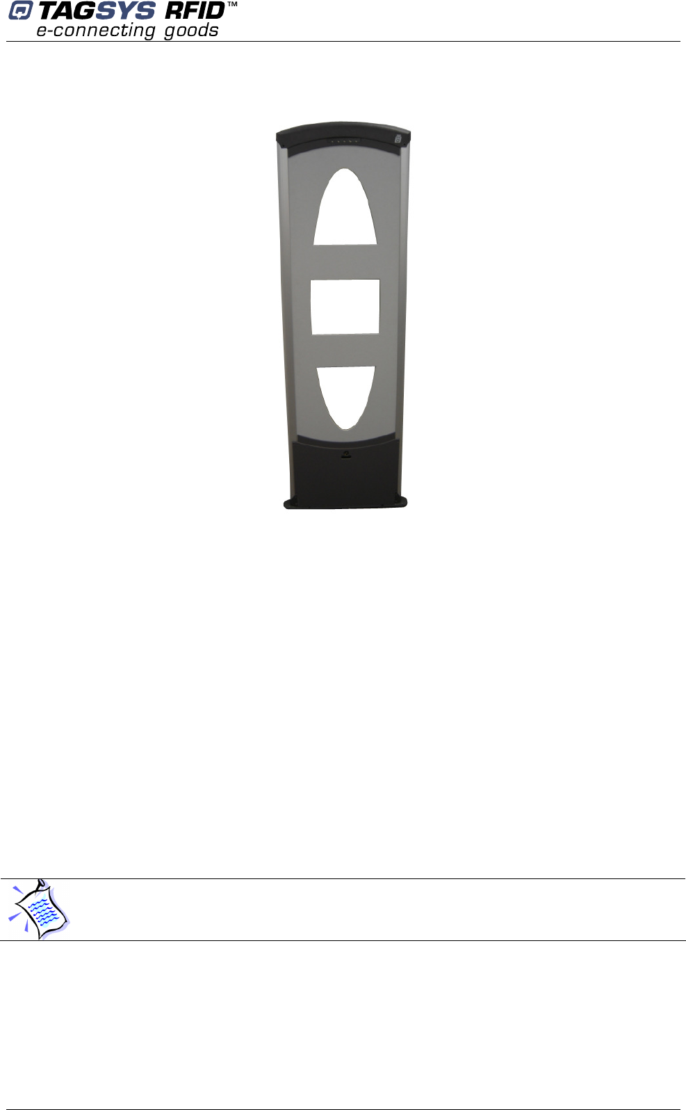
3.2 Brief L-SP2 Description
The components of the L-SP2 EAS system are contained within the L-SP2 pedestal. At
least two pedestals are required for each EAS gate. A set of pedestals is known as a gate and may
consist of several pedestals. Please see section 4 “Installation” for more information.
The L-SP2 is built in a one frame:
A L-SP2 Electronics unit is used to control each pedestal. This electronics unit
generates the RF signal transmitted by the antennas and picks up the reply from the
RFID tag. If an activated RFID tag is detected, the electronics unit will activate the
alarm of the LED/buzzer board on the pedestal.
These antennas are sensitive receivers used to detect the theft bit status of the RFID
tag as it passes through the EAS gate.
A warning visual and audible device (LED/Buzzer board)
A remotely accessible people counter equipped with a photoelectric sensor
To operate, the L-SP2 will only need a power supply cable.
In standard configuration the Ethernet interface is not provided. If the Ethernet version is
chosen then provide a second sheath for the Ethernet cable.
Library Security Pedestal 2
18/62 Revision 4.2 July 2008
4 Installation
4.1 Recommendations before Installation
4.1.1 Wire Feed Sheaths
Within the framework installation you need a power supply cable sheath and an Ethernet
cable sheath for the Ethernet network with Ethernet version. These sheathed cables will be
located at the bottom center of the pedestal as shown in Figure 9.
The L-SP2 is delivered with a power supply cable of 1-meter length located underneath of the
pedestal at the bottom center.
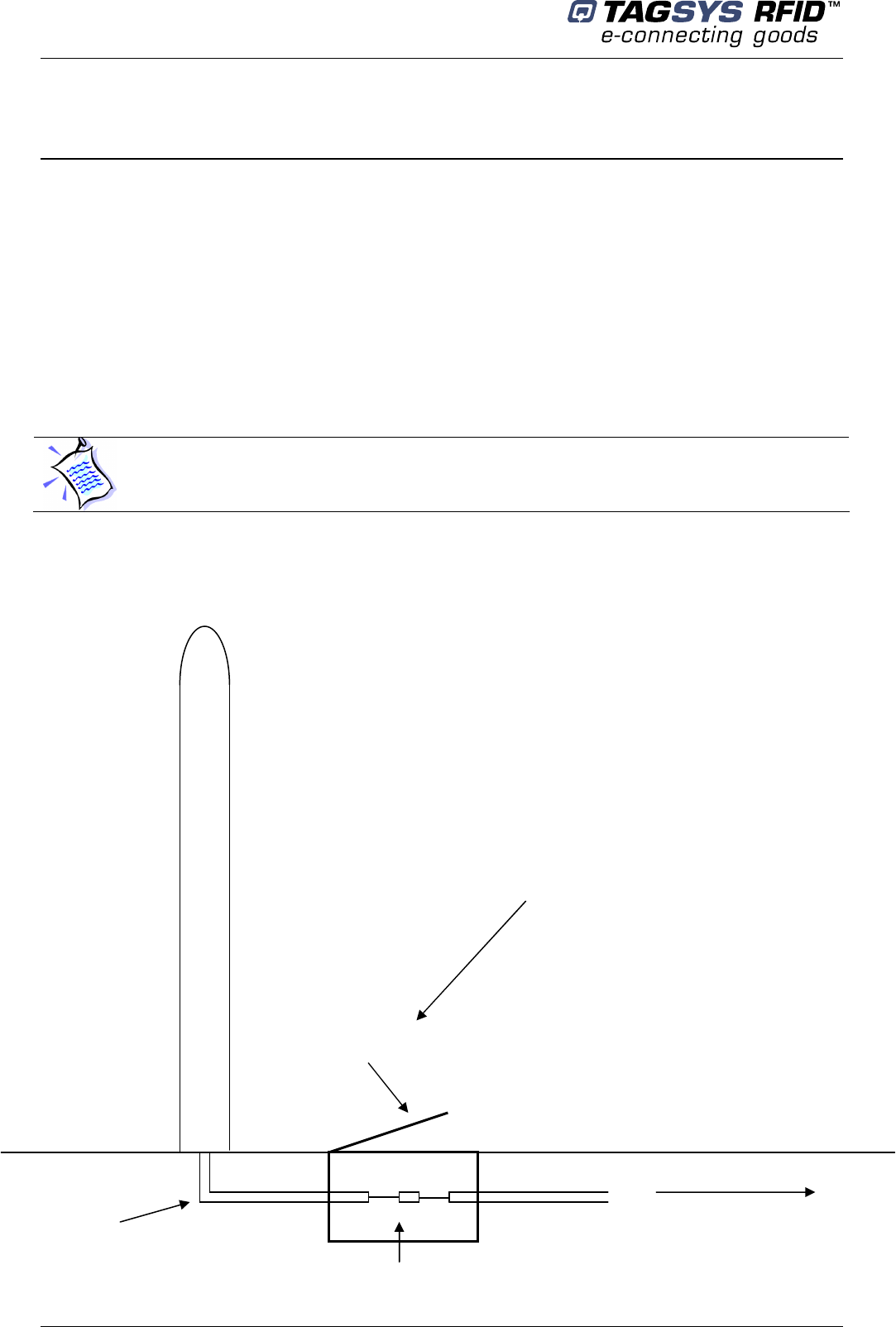
Figure 2 below shows an example of installation and connection of the L-SP2.
Figure 2: Electric Connections
The L-SP2 Ethernet version is provided with a 1meter Ethernet cable.
LSP2
Inspection
door
Toward primary networks
(AC Mains + Ethernet)
Electric
sheath
Connecting box
Power supply connection
(RJ45 for Ethernet)
Installation
July 2008 Revision 4.2 19/62
4.1.2 Electrical Safety Rules
The mains powers the L-SP2 so it is necessary to provide a differential protection and a
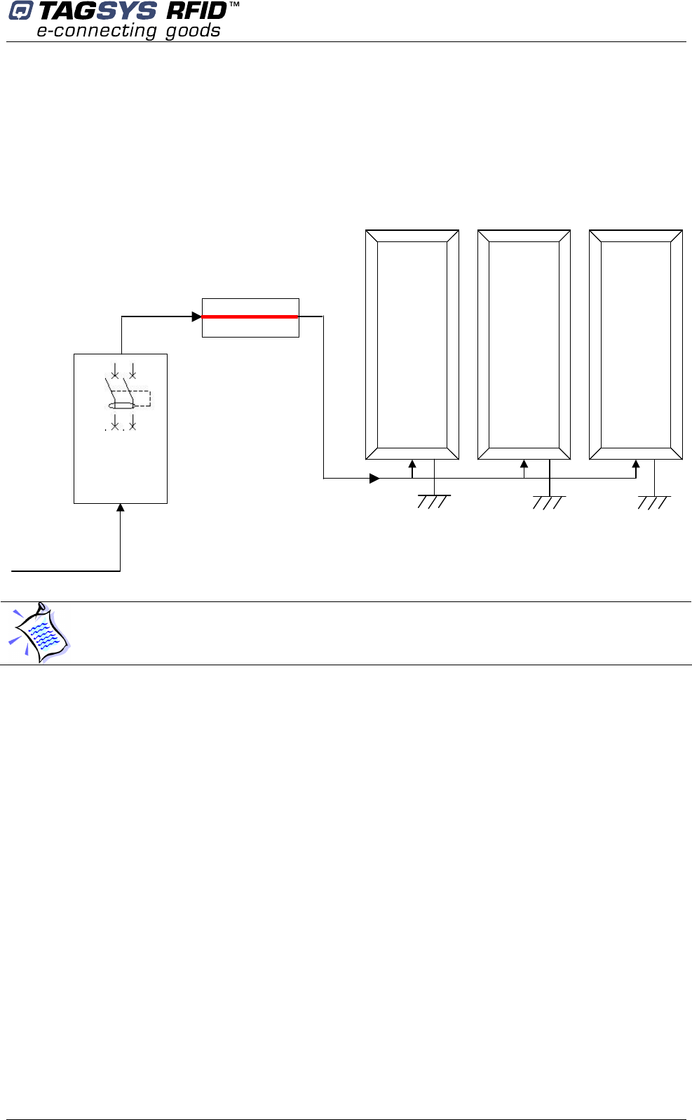
shutting-off device. Figure 3 below shows how to connect the L-SP2 pedestals to the mains.
Figure 3: Safety Electrical Installation
Micro
circuit
breaker
Differential
circuit
-
breaker
AC main line
+
Neutral
AC main
L-SP2
L-SP2
L-SP2
The power supply cable provided is of PVC type, H05VVF 0.75 mm² multi-stranded (14 AWG) and
complies with FEC60950 standard.
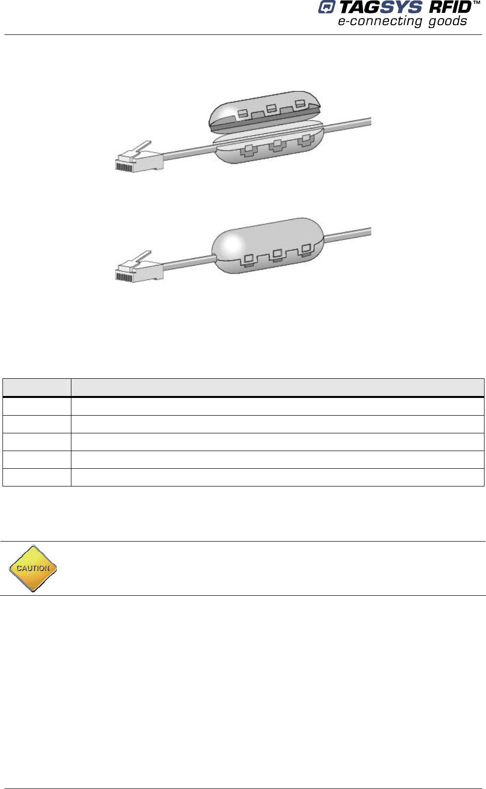
4.1.3 Network cable installation
The LSP2 Ethernet version is provided with an Ethernet cable mounted with a ferrite for LAN
cables. If the cable is to be changed, you will have to add a ferrite to this cable.
References:
• Ethernet cable: Unshielded Ethernet cable, UTP-Cat5
• Ferrite for LAN cable: Würth Electronik (Manufacturer ref: 742 7111)
This ferrite will have to be installed as follow (Figure 4):
• Inside the electronic casing
• Near the Moxa board
• 20mm maximum distance from the RJ45 connector.
The electrical installation must be carried on by qualified personnel only. Micro circuit breaker
and differential circuit-breaker ratings depend on country regulations in force.
Library Security Pedestal 2
20/62 Revision 4.2 July 2008
Figure 4: Ferrite clamp mounted on Ethernet cable
4.2 L-SP2 EAS System Components
The components included in the L-SP2 EAS System package are listed in Table 1
Table 1: L-SP2 EAS System Components
Quantity Description
1 L-SP2 Pedestal
8 40 mm Philips-head, countersunk screws with a diameter of 6 mm
8 8 mm plastic cement plugs
1 L-SP2 EAS System CD-ROM
1 RS 232 cable (system configuration)
4.3 L-SP2 Pedestal
4.3.1 Tools Required
The following tools are required during installation:
Tape measure
Square
Drill with 4 mm, 8-mm and 19-mm bits
Philips-head screwdriver
Level
CAUTION: This equipment is intended for indoor use only under the conditions described in
this document. Should it be used outside these conditions cannot be guaranteed, and is not
recommended. Please read section 1 “Publishing Information” before installation or use.
Installation
July 2008 Revision 4.2 21/62
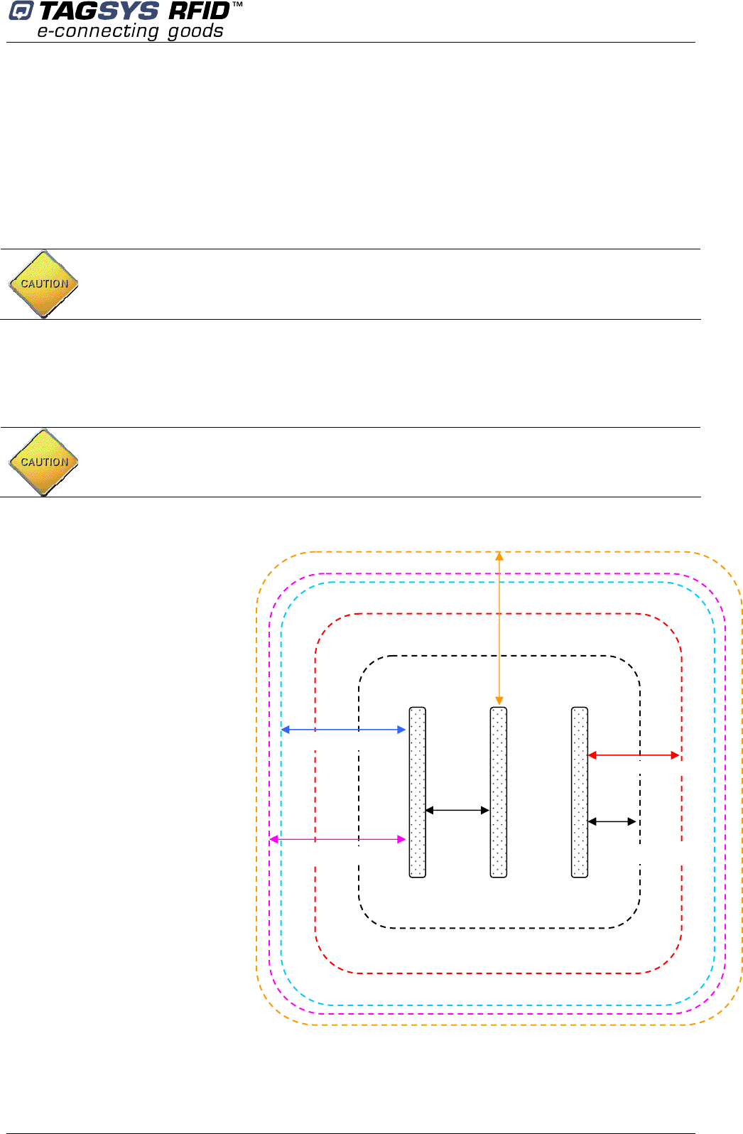
4.3.2 Placement of Pedestals
Pedestals must be mounted between 800 and 915 mm apart (edge to edge) for maximum
reliable performance. There should be at least one pair of pedestals at each entrance/exit point of
the library. There should be a pedestal at each edge of the entrance, and a clear space of at least
500 mm around the edge of the pedestals to ensure that the antennas will not be detuned. This
clear space must not contain any metallic objects, but may contain some substrates such as non-
metallic/non-conductive building materials such as wood, glass, chipboards and plasterboards.
Be cautious to properly align the pedestal in order to centre the photoelectric beam sensor on the
reflector of the next pedestal.
Figure 5: Clearance around Pedestal
A: Indicates the distance (6 ft.
6in.) to a permanent librarian
position.
B: Indicates the distance (8 ft.)
from other RFID stations.
C: Indicates the recommended
distance (36 in. face panel to
face panel) between
pedestals.
D: Indicates the minimum
distance (31½ in.) between a
pedestal and large metal
object.
E: Indicates the minimum
distance (20 in.) between a
pedestal and small metal
object.
F: Indicates the minimum
distance (30 ft.) between
Master pedestals (specific
synchronization ID, see
section 5.2 “Understanding
the L-SP2 Synchronization
Process”).
CAUTION: In case several pedestal row to be installed it is recommended every L-SP2 gate
being positioned in the same direction (the people counter of each looking toward the same
direction)
CAUTION: Each L-SP2 should be installed within following tolerances:
Horizontal angular alignment tolerance with reference to pedestals alignment: 0° +/-2°
Vertical angular tolerance with reference to ground surface : 90° +/-1°
C
36 in.
(91.4 cm)
A
6 ft. 6 in. (2 m)
F
30 ft. (9.1 m)
B
8 ft. (2.4 m)
D
31½ in. (80 cm)
E
20 in. (50 cm)
Library Security Pedestal 2
22/62 Revision 4.2 July 2008
4.3.3 Installing the Pedestal
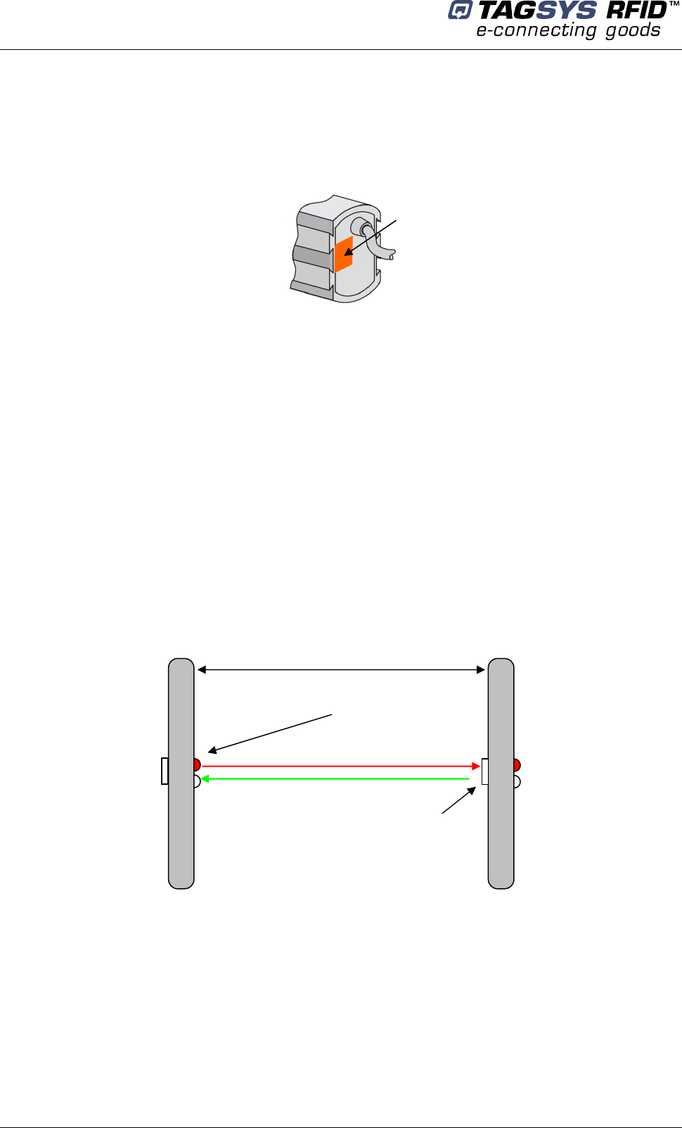
Once the L-SP2 will be powered, the photoelectric sensor will emit a red light beam. To
precisely align the sensor and the reflector, an orange LED is present on the back of the
photoelectric sensor. When the orange LED is continuously on, the sensor and the reflector are
perfectly aligned.
Figure 6: Photoelectric sensor
On the contrary the orange LED is blinking, and then you have to adjust the photoelectric sensor,
so that the red light beam is centered with the opposite reflector. This operation is achieved using a
white paper to clearly see where the red light beam is pointed at. When perfectly centered, the
orange LED will continuously be ON.
Special attention must be taken for the 2 pedestals positioning:
They must be positioned face to face
They must be parallel
They must be aligned
The orange LED must be continuously ON when powered
Then the 2 pedestals can be secured to the ground.
A good positioning will ensure the red LED beam to be reflected by the reflector as shown below.
Figure 7: Top view of correct L-SP2 installation
Light beam
Reflector
Parallel
Orange LED
Installation
July 2008 Revision 4.2 23/62
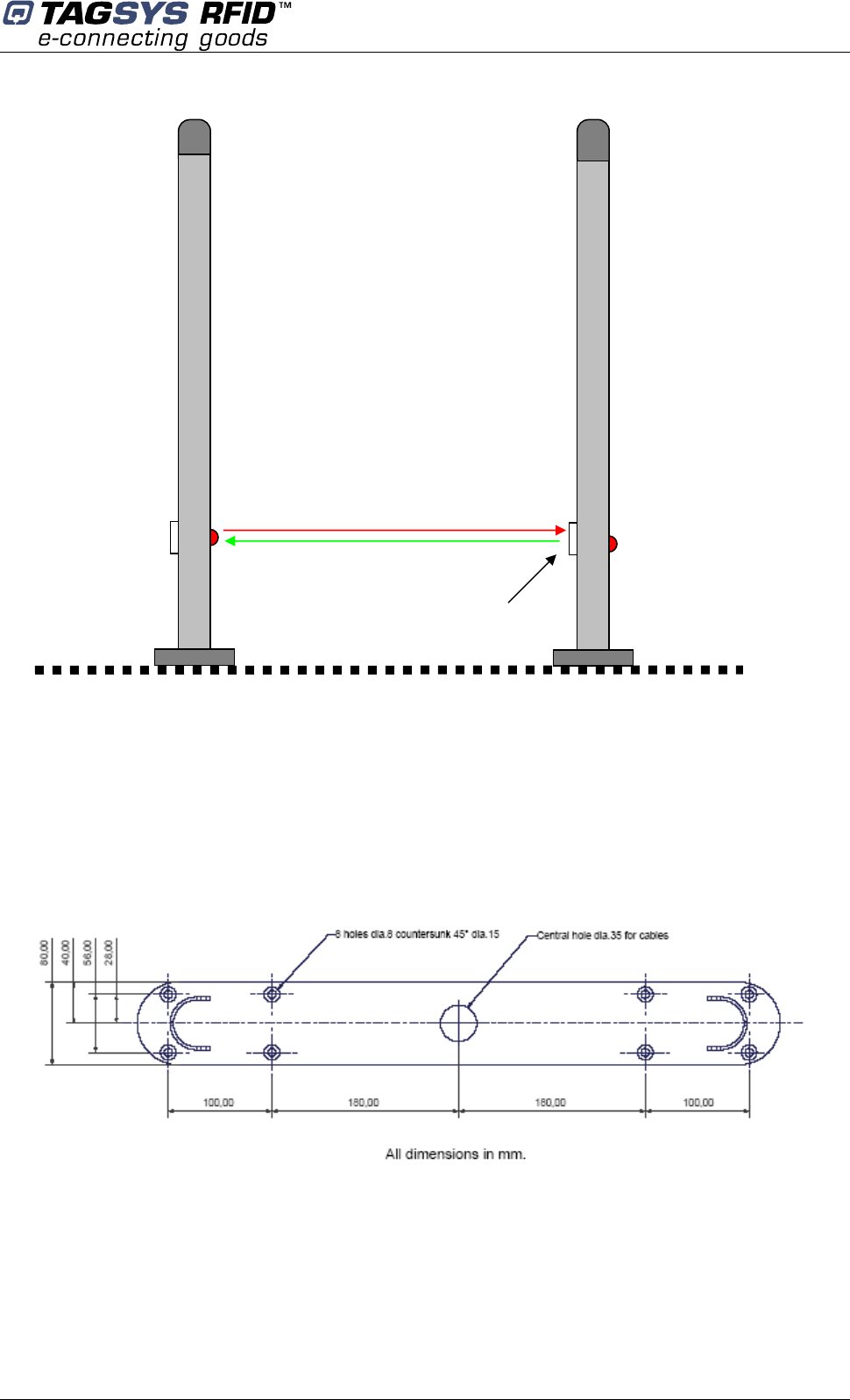
Figure 8: Side view of correct L-SP2 installation
The L-SP2 pedestal is mechanically compatible with the Smarto L122 Pedestal.
After having defined the location of the pedestals, refer to the mechanical drawing of the pedestal-
mounting diagram (Figure 9). The pedestal is fastened to the floor using screws that are strong
enough to support the weight of an average adult falling against the pedestal.
Figure 9: Pedestal Mountings
1. Identify and mark the location of the holes to be drilled for mounting the pedestal to the ground.
The use of a tape measure and a square is recommended.
2. Drill the cable access and mounting holes according to the type of ground surface:
a. Wood floor: Drill eight holes with a diameter of 4 mm for the mounting screws and one
hole with a diameter of 19 mm for the cable access.
Ground
Reflector
Library Security Pedestal 2
24/62 Revision 4.2 July 2008
b. Cement floor: Drill eight holes with a diameter of 8 mm for the cement floor plugs and
one hole with a diameter of 19 mm for the cable access. It may be necessary to provide
a groove for the power supply cable connected to the L-SP2 Electronics Unit. Insert the
concrete floor plugs into the mounting holes.
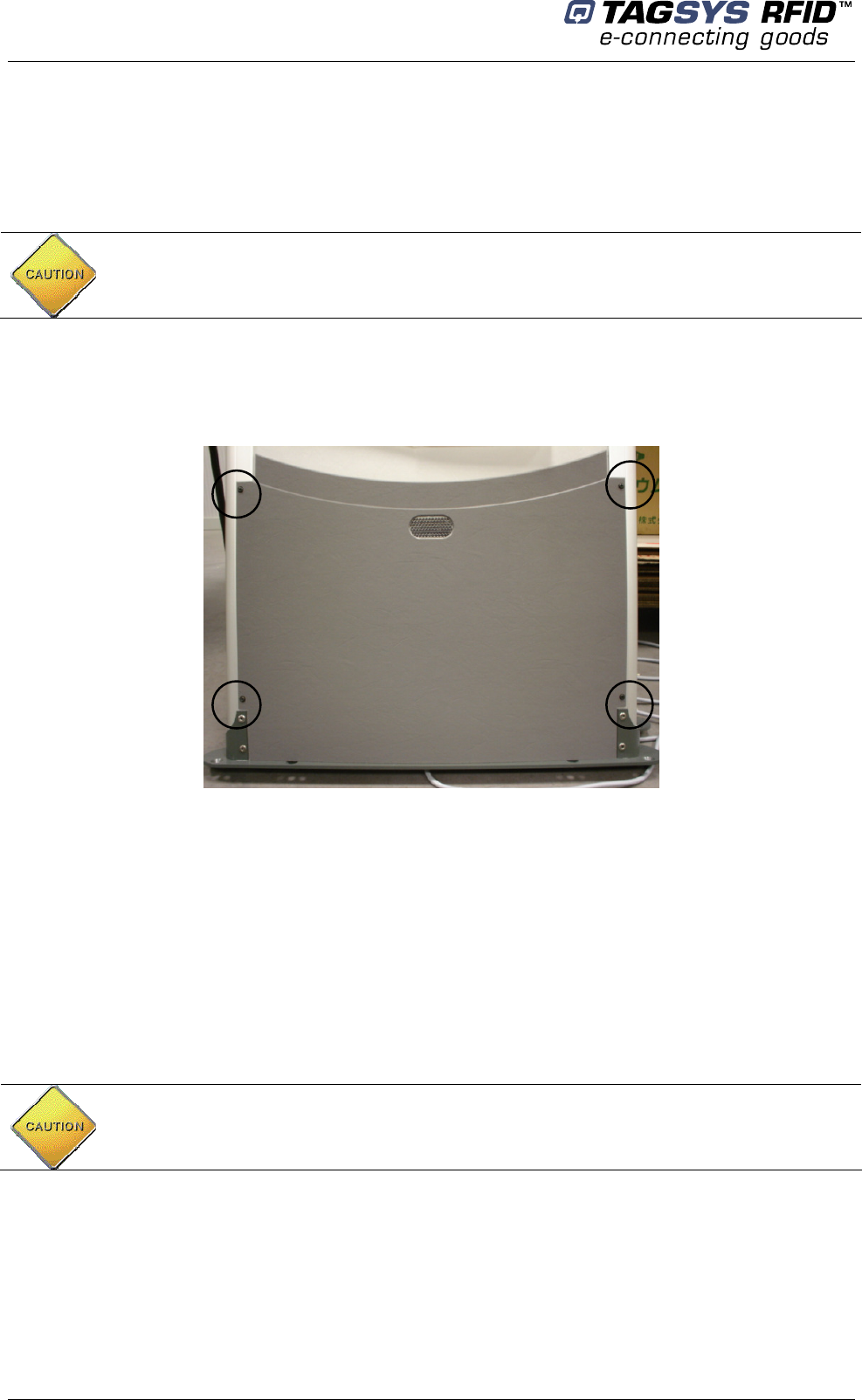
3. Remove the pedestal from the box.
4. Remove the plastic cover from the both sides after removing the 4 fixing screws.
Figure 10: L-SP2 Bottom (4 screws)
5. Engage the power supply cable in the electric sheath and if available the Ethernet cable in the
other sheath (please refer to section 4.1.1 “Wire Feed Sheaths”).
6. Place the pedestal base over the mounting holes. Insert and fasten the screws in the mounting
holes according to the type of ground surface:
Wood floor: Insert the screws directly into the mounting holes and tighten the screws in
place.
Concrete floor: Insert the screws into the concrete floor plugs and tighten the screws in
place.
7. Connect the cables in the connection box as show in Figure 2 with respect to the following
rules:
CAUTION: Always use a protective sleeve for main power cable, which match to the non-
inflammability standard. Main power cable must be a 3 wire (line, neutral and earth), multi
stranded copper wire, 0.5 mm²/ 3A)
When tightening the screws in place, first tighten the screws in place ¾ of the way. Once all
screws are in place, then tighten each screw progressively, one after each other to ensure
that the floor bracket is solidly fixed into place and completely vertically aligned. The use of a
level may be required.
‘Phase’ wire is brown
‘Neutral’ wire is bleu
‘Ground’ wire is yellow/green
Installation
July 2008 Revision 4.2 25/62
8. Once all the L-SP2 pedestal have been installed, close the micro circuit-breaker (Figure 3) to
power up the system before starting configuration operations. Please see section 5
“Configuration”.
9. After the configuration has been carried on, replace the two plastic covers and tighten the 4
fixing screws.
AC mains 110/220V. Be sure that there is no power supply current before carrying on the
connection operation. To do so, the micro circuit-breaker must be opened. (Figure 3)
Library Security Pedestal 2
26/62 Revision 4.2 July 2008
5 Configuration
All configuration operations of L-SP2 systems are carried on with the L-SP2 Configuration Utility
Software.
5.1 Chip Configuration
5.1.1 Scanning Duration
For optimal performance the scanning duration (Tscan) should not exceed 250ms. Tscan is
the period to scan all the pedestal of a group. Depending on your chip configuration and the
number of pedestal installed you can determine the scanning duration of your installation.
Table 2: Scanning Duration
No Read Memory Read Memory
Synchronization duration 6ms 6ms / pedestal
C220 / C320 25ms / pedestal 80ms / pedestal
C370 / C370-L EAS 35ms / pedestal 100ms / pedestal
C370 / C370-L / Tag-It /
Generic ISO15693 AFI 80ms / pedestal 65ms / pedestal
Example 1: with a 3 pedestals system using the C220 + C370-EAS without Read-Memory
The scanning duration will be: Tscan = 6ms + (25ms+35ms) x 3 = 186ms
Example 2: with a 3 pedestals system using the 370-AFI + Read-Memory.
The scanning duration will be: Tscan = (6ms+65ms) x 3 = 213ms
5.1.2 EAS Mode versus AFI Mode
EAS mode is only supported by the C370 or C370-L (NXP chip). AFI mode is supported by every
ISO15693 chip, whatever the manufacturer (NXP, Texas Instrument, ST …).
In non-Read memory mode, EAS mode is faster than AFI mode, therefore it helps keeping a low
scanning duration in case of a high number of pedestals.
In Read memory mode, AFI mode will give better results. AFI mode will allow specific addressing
of items which are stolen. Therefore the LSP2 will be able to read the memory of multiple stolen
items.
This is not possible in EAS mode; the read memory can not be addressed using the EAS status of
the item. Therefore, the LSP2 will only read the memory of one item. In the case of one stolen item
among multiple checked-out items, the LSP2 would retrieve the memory of one of them, whatever
its EAS status.
5.2 Understanding the L-SP2 Synchronization Process
5.2.1 Standard Synchronization Mode
To manage a group of pedestal, a synchronization burst is sent by the master gate to all the
slaves’ gate. This is called the synchronization process.
Configuration
July 2008 Revision 4.2 27/62
Only one gate is defined to be the master who emits a synchronization burst to the slaves
in close proximity.
The other gates, configured as slave, synchronize themselves on the master’s burst, and if
they have a matching ID, scan the configured chip.
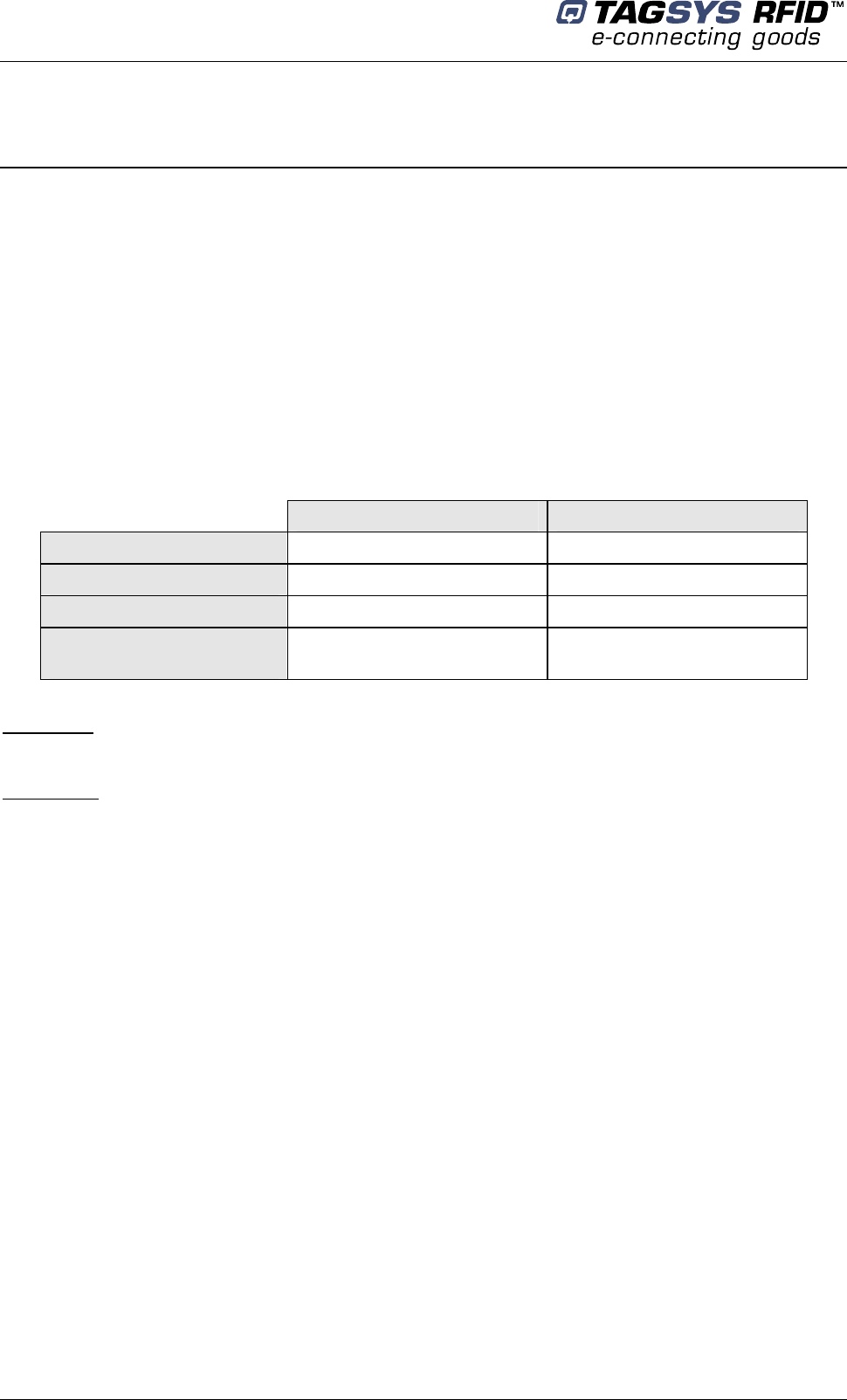
Figure 11: Chronogram Sample (1 Master/ 4 Slaves)
MASTER
SLAVE1
SLAVE2
SLAVE 3
SLAVE 4
Synchronization burst: start burst to synchronize the gates (Period of Tscan ms)
Processing time (Pt): depends on the number of chip types to be detected. The faster is
when only one chip type is selected (see Table 2: Scanning Duration).
The Tscan period is optimized according to the number of slaves and number of chips to
detect.
5.2.2 Special Synchronization Mode
This mode has an identical Master/Slave configuration as described in the Standard
Synchronization mode.
Synchronization process:
1- The master scans the configured chip, then send the synchronization burst to Slave1
2- Slave1 scan the configured chip, then send the synchronization burst to Slave2
Default configuration of the L-SP2 is set to Master.
Only used in ISO15693 (C370/C370-L/Tag-It) AFI mode with Read-Memory activated.
Synchronization
burst
Tscan
Pt
Library Security Pedestal 2
28/62 Revision 4.2 July 2008
3- Slave2 scan the configured chip, and then send the synchronization burst back to the
master.
This process is repeated in an infinite loop mode.
In case of the master does not receive back the synchronization burst from the last slave after a
defined period, it will automatically restart the synchronization process.
5.2.3 Wireless Synchronization
The L-SP2 is provided with a wireless synchronization system, however slaves too far from
the Master pedestal cannot be reached and the air synchronization signal is not transmitted to the
slaves pedestal, in this case synchronization by wire is mandatory.
When more than two pedestals are installed, it is recommended to install the Master in the middle
of the slave’s line for a better propagation and detection of the air synchronization burst.
Figure 12 below shows an example of optimal configuration.
Figure 12: Configuration sample
In this particular mode we recommend to install a maximum of 3 pedestals in order to avoid
deteriorating the Tscan duration described in section 5.1”Chip Configuration”.
In Standard Synchronization mode, section 5.2.1, if more than 5 pedestals are to be installed
or distance between pedestals exceeds the recommendation of section 4.3.2 “Placement of
Pedestals”, wire synchronization is mandatory.
Configuration
July 2008 Revision 4.2 29/62
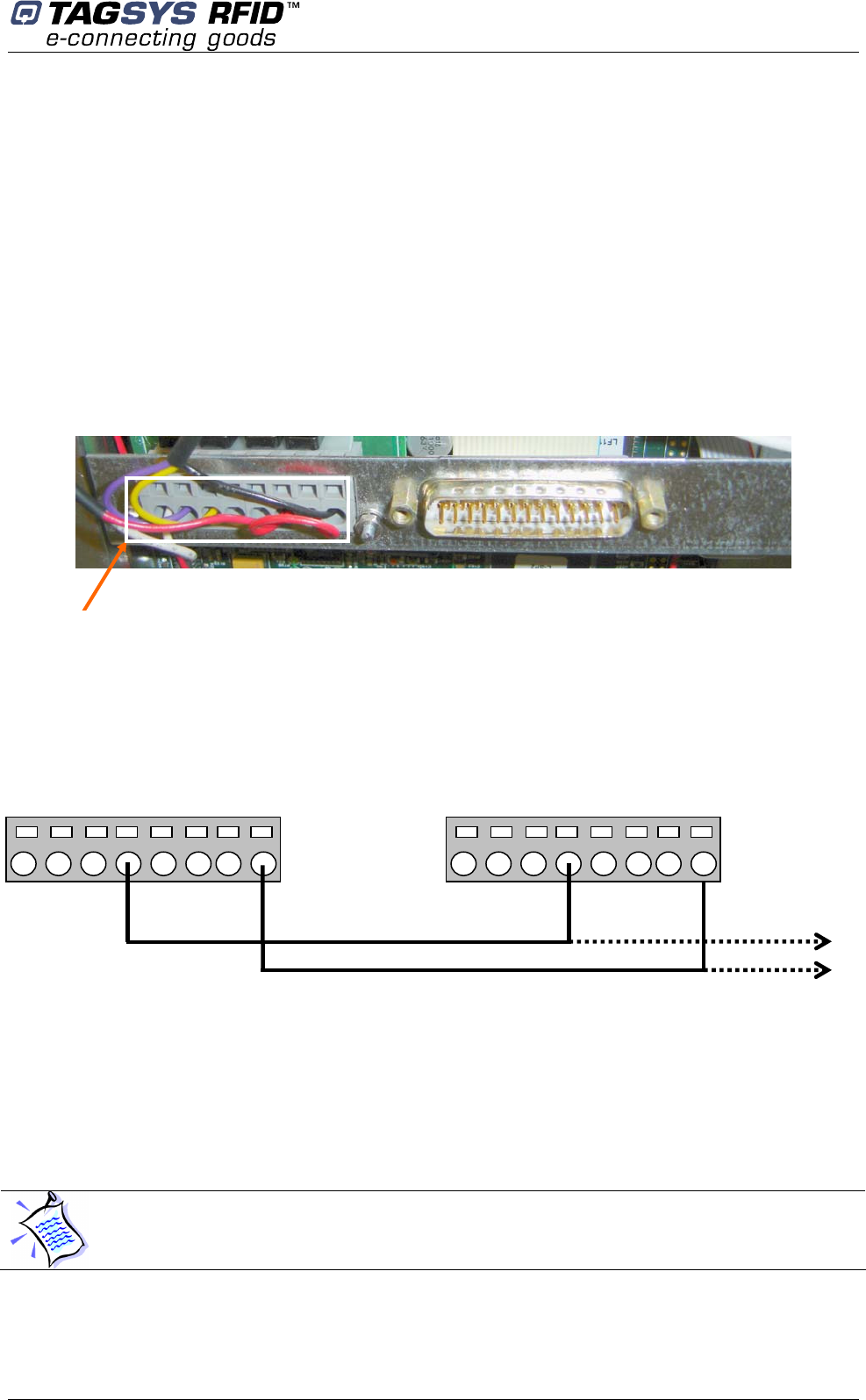
5.2.4 Synchronization by Wire
In this case the L-SP2 configuration settings are not to be changed. There will always be one
L-SP2 Master and others pedestals set as Slaves. Each pedestal is connected to the other using a
twisted pair cable.
Wire connection:
1. Unscrew the 4 screws to open the plastic panel
2. Unscrew the 9 screws to open the metallic cover
Figure 13: I/O port support
3. Use a thin sharp screwdriver to insert the wire terminal inside the I/O port 4 hole (please
see below Figure 14.
Figure
14
: Wire disposition
4. Repeat this sequence for each L-SP2 pedestal to connect each I/O port 4 together
5. Power up the whole system (every pedestals must be powered up) and check that the
synchronization process works properly
6. Replace the panels
5.3 Configuration of the Ethernet Interface
Don’t forget to power up your installation before carrying on the following steps
I/O port
support
1 2 3 4 GND
LSP2 #1 LSP2 #2
LSP2 #3
1 2 3 4 GND
Library Security Pedestal 2
30/62 Revision 4.2 July 2008
For the Ethernet version, the first step is to allocate a unique IP address to each L-SP2.
This operation will allow identifying each L-SP2 on site before configuring them on the Ethernet
network.
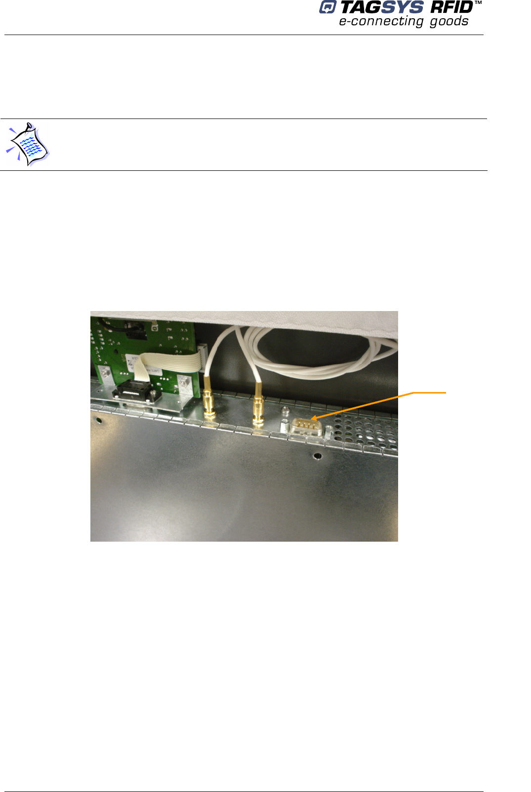
Setting of L-SP2 IP addresses can be done in console mode using the HyperTerminal software via
the RS232 link on DB9 connector as shown in Figure 15.
Communication parameters are the followings:
Baud rate: 19200
Data bits: 8
Parity: none
Stop bit: 1
Figure 15: Configuration Connector
1. Once the communication parameters have been set, type any key to switch from Data
mode to Console mode.
2. Type 2 to select “Network settings” and then press Enter.
3. Type 1 to select “IP address” and then press Enter.
4. Use Backspace key to erase the current IP address, type the new IP address then press
Enter.
5. Return to Main menu, and select “Save/Restart” to memorise the configuration.
For more information regarding the IP addresses setting please see Moxa NE-4100 Series User’s
Manual available on http://www.moxa.com.
Once all the IP addresses have been allocated, the L-SP2 plastic covers can be replaced.
By default the IP address is 169.254.0.100 (port 4001) (IPv4 Automatic Private IP
Addressing). Ask your network administrator to obtain a static IP address for each of the
pedestals connected to your local network.
Configuration
Port
Configuration
July 2008 Revision 4.2 31/62
The L-SP2 configuration will be carried on using a host computer connected to the local Ethernet
network.
5.4 Configuration of the L-SP2
“L-SP2 Configuration” is the software tool used to communicate and configure the L-SP2
pedestal. This software handles communication either using the serial port or Ethernet port.
Depending on the L-SP2 version, the configuration of the whole L-SP2 installed on site is carried
on according to the following methods:
If the Ethernet version is selected on site; the whole L-SP2 configuration can be carried on
from a host computer connected to the local area network. Each L-SP2 is addressed
thanks to its own IP.
If the standard version is selected on site; the whole L-SP2 configuration will be carried on
after connecting each pedestal with the RS232 interface as shown in Figure 15, the
Master/Slave statute depending on neighboring systems.
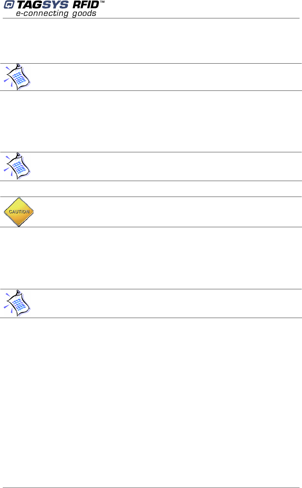
5.4.1 Installing the Configuration Software
The L-SP2 Configuration Utility is on the CD-Rom provided with the L-SP2.
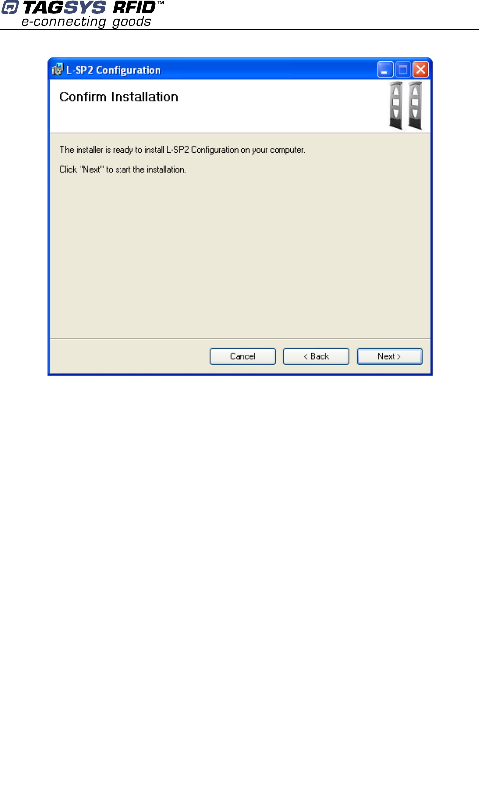
Launching the Installer from the CD-Rom will display the following window:
You can localize the each gate thanks to their IP address. Their on site location must be
known to configure and set them as Slaves or Master.
Before you configure the whole L-SP2, you need to have a clear vision of which systems will
be the Masters or the Slaves. (Refer to section 5.2 “Understanding the L-SP2 Synchronization
Process”)
CAUTION: In a configuration case with several pedestals, as pedestal is default Master
configured, they will mutually perturb when powered on. So the first step will be to set the
Slaves pedestals chosen as Slave.
When the Ethernet version is installed, the L-SP2 configuration can only be carried on via the
Ethernet connection. The DB9 configuration connector as show Figure 15 is only used to set
the Ethernet interface and cannot be used to configure the L-SP2.
Library Security Pedestal 2
32/62 Revision 4.2 July 2008
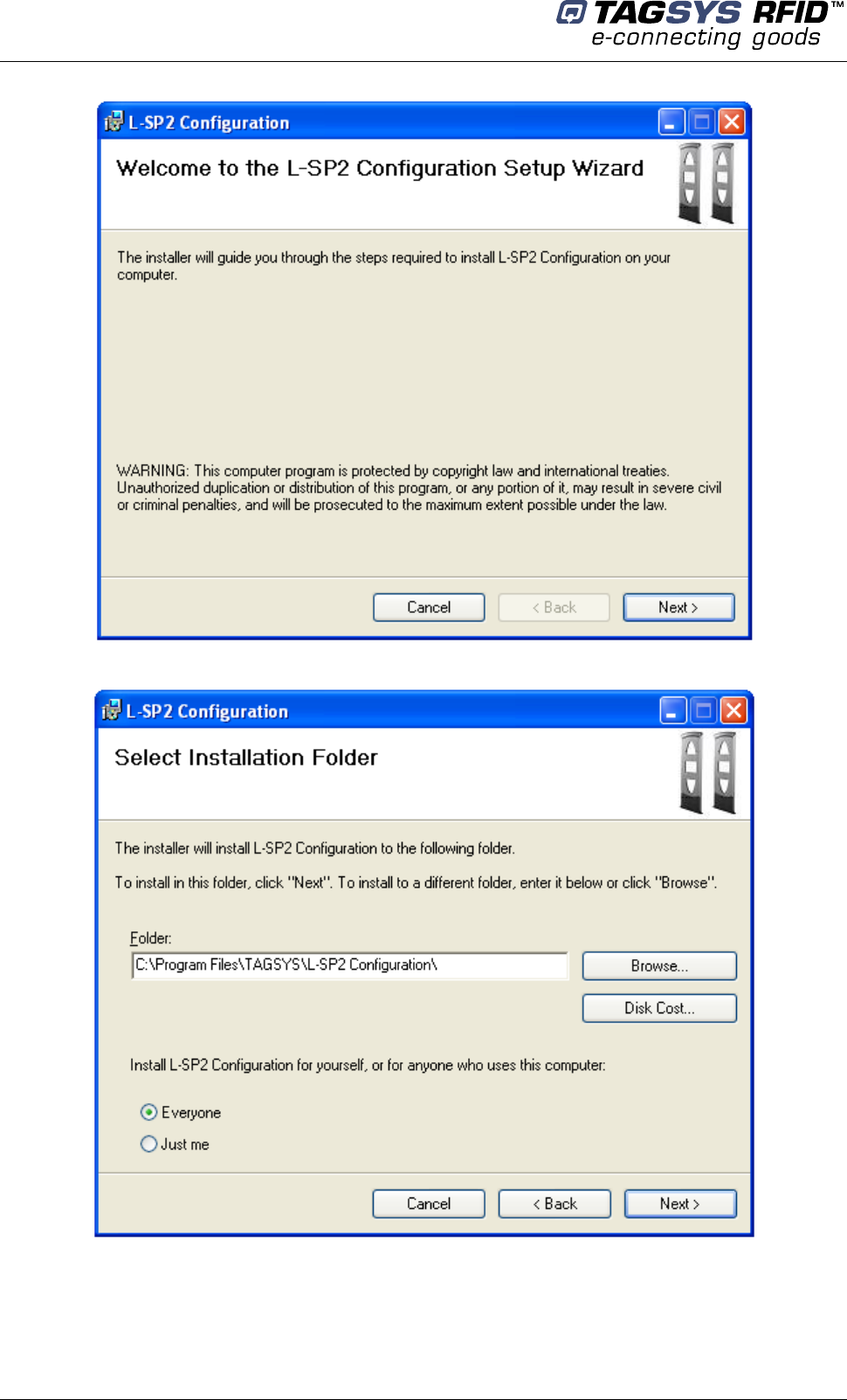
Follow the installer steps:
Configuration
July 2008 Revision 4.2 33/62
After the L-SP2 Configuration Software is installed, a shortcut to the application will be added to
the desktop and to the Start Menu.
Library Security Pedestal 2
34/62 Revision 4.2 July 2008
5.4.2 Basic Configuration
Double-click on the application shortcut to start the application.
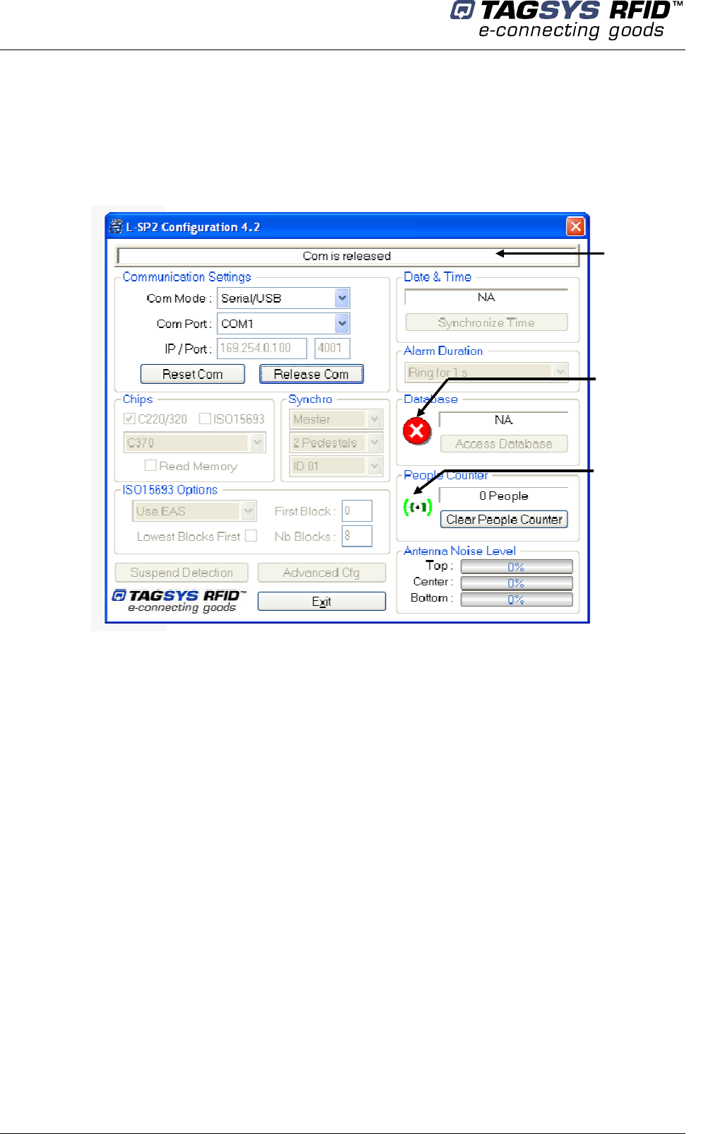
By default, the application searches for a serial L-SP2 connected to the COM Port 1.
If no L-SP2 is detected on this COM Port, the following window is displayed:
Figure 16: Main Configuration Window, not connected to the L-SP2
Select the COM Mode for your L-SP2 between Serial and Ethernet.
If Serial then select the Com Port (1 to 8 available)
If Ethernet then enter its address and TCP port
Alarm
: icon lights ON
when EAS is detected
Connection
status
Counter Icon
:
light ON if counter is
incremented or beam crossed
Configuration
July 2008 Revision 4.2 35/62
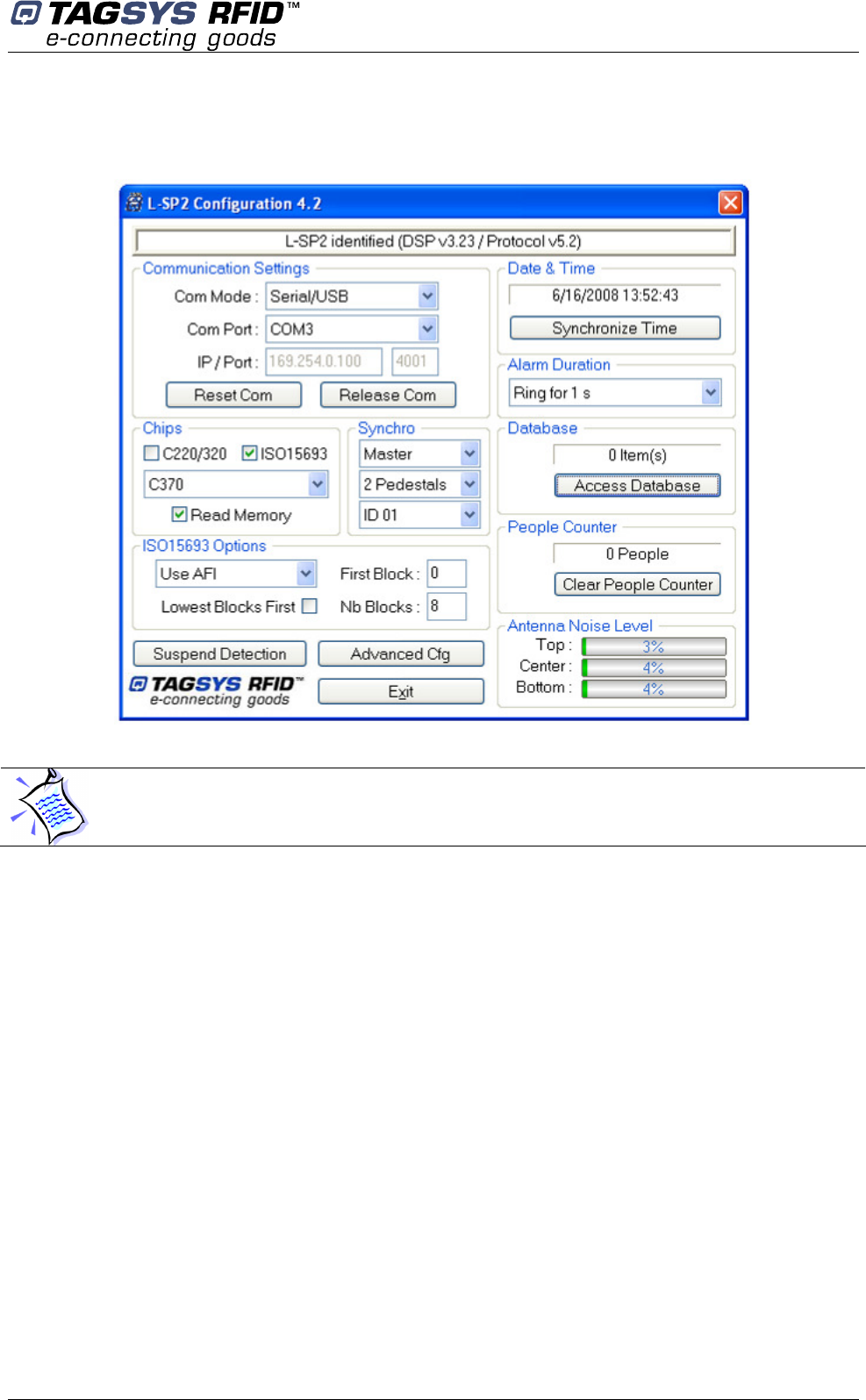
Click “Reset Com” to establish communication to the L-SP2. If settings are correct the following
window is displayed:
Figure 17: Main Configuration Window, connected to the L-SP2
Reset Com
Reset the communication to the pedestal regarding Com Mode, Com Port and IP/Port settings.
Release Com
Release the communication to the pedestal. (Get back to Figure 16 )
Chips
Select the chips to be detected
Read Memory
When selected, the L-SP2 will try to read memory of items passing through the gate. 1 block = 32
bits, maximum 8 blocks.
Use AFI / Use EAS (ISO15693 only)
Selected which mode you want to use to detect an ISO15693 item.
First Block (ISO15693 only)
First memory block to be read (in the range from 0 to 7).
Nb Blocks (ISO15693 only)
Number of blocks to be read (in the range from 1 to 8).
Once the communication is set and the system identified, the software displays the current
configuration recorded in the L-SP2.
Library Security Pedestal 2
36/62 Revision 4.2 July 2008
Lowest Block First (ISO15693 only)
Activate this option if you want the lowest memory block to be presented first in the database
Synchro
Select whether the pedestal is to be configured as the Master or as the Slave (1, to …8)
Pedestal Number: set the total number of pedestals (master + slaves) in close proximity
and sharing the same ID.
Select ID (same ID for Master and slaves for one system installation)
This parameter is the identifier of the Master and when a pedestal is configured as a Slave
it is the Master’s ID that the slave will answer to. For a Master/Slave system it is mandatory that all
the pedestals use the same ID.
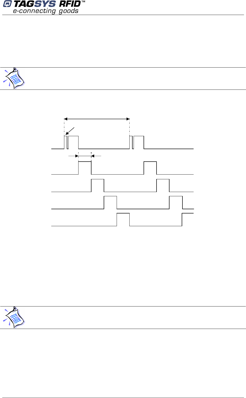
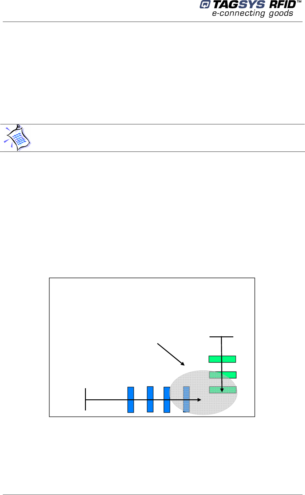
In the library configuration example below we have:
system A with ID = 1 (M1 Master, S1, S2, S3 Slaves)
system B with ID = 2 (M2 Master, S1, S2 Slaves)
The Masters are disposed as far as possible from each other not to perturb themselves. (Please
refer to section 4.3.2 “Placement of Pedestals").
Two different IDs to be sure that each slave will be synchronized with the master from its own
system.
Figure 18: Multi-gate Configuration with 2 different Ids
Alarm
Select alarm time (using a time step of 0.5 s. From 0.5 to 5 s)
Resume Detection
Click the button to stop EAS/AFI detection. Another click resumes EAS/AFI detection.
Only one Master can be selected with several slaves.
System A
With
ID = 1
System B
With
ID = 2
Nearby proximity
area with
interferences
S1 M1 S2
S3
S1
M
2
S2
Configuration
July 2008 Revision 4.2 37/62
Once you have set the basic configuration check that all the slaves are well synchronized. To do
so, L-SP2 electronics unit green LEDs should flicker cyclically. If not, proceed to the advanced
configuration stage.
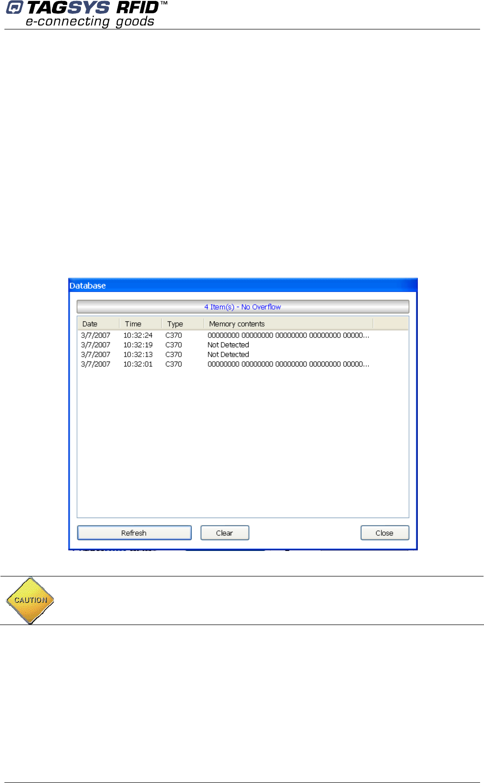
Database
Each time an item (with EAS/AFI activated) passes through the gates an entry is added to a local
database in L-SP2 memory. This entry holds the following information:
The date and time to which the theft was committed.
The chip type (C220/C320, C370, C370-L, ISO15693).
If selected, the memory data.
The database section shows the number of entries stored in L-SP2 memory in real-time.
Access Database
To access the database, click “Access Database”: Database is downloaded and the following
window is displayed:
Figure 19: Database
Click:
“Refresh” to re-download Database.
“Clear” to ERASE L-SP2 Database.
“Close” to close the window.
You can access the database from your own application using MedioSTX.dll and Java SDM.
Please refer to the Medio STX Windows DLL Programming Guide.
CAUTION: When this window is open EAS/AFI detection is automatically suspended. It is
resumed when the window is closed.
Library Security Pedestal 2
38/62 Revision 4.2 July 2008
Date & Time
The top of this section continuously displays date and time of the pedestal.
Click “Synchronize Time” to synchronize the pedestal to the PC clock.
Antenna Noise Level
These bar graphs provide a feedback regarding the ambient noise level measured by each
antenna. It is only provided as debug purpose and should no be seen as a measure of
performance. Moreover, this information is only provided in conjunction with the ISO15693 chip
and is not supported if only the C220/C320 is activated.
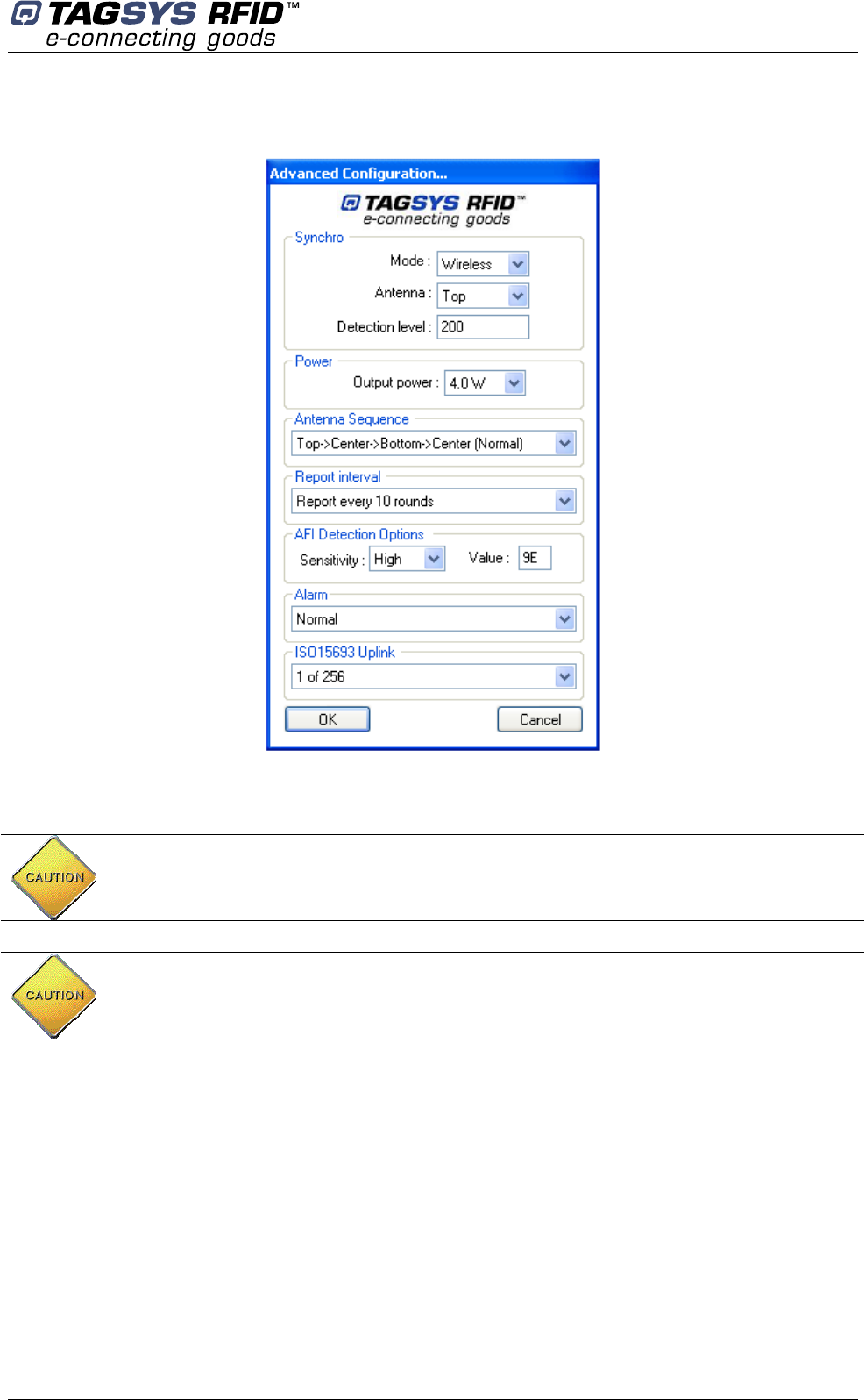
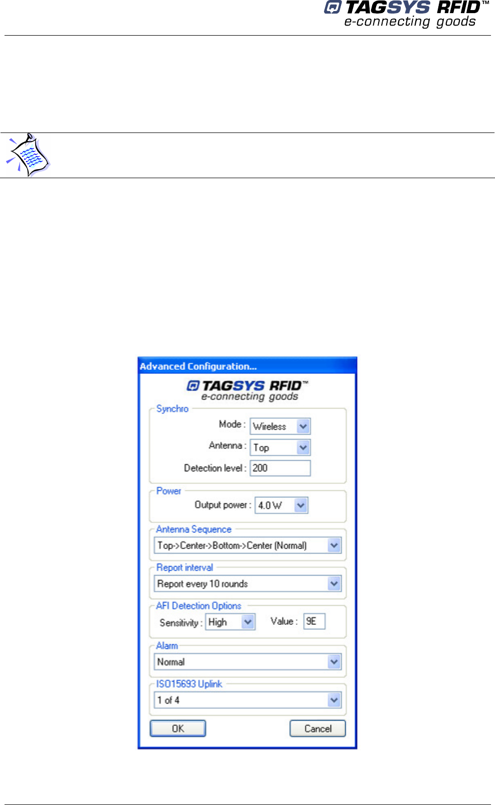
5.4.3 Advanced Configuration
Press Advanced Cfg (Configuration) button to set advanced parameters.
The following window is displayed:
Figure 20: Advanced Configuration window
Be advised that this time will be used as a date stamp when a theft is committed.
Configuration
July 2008 Revision 4.2 39/62
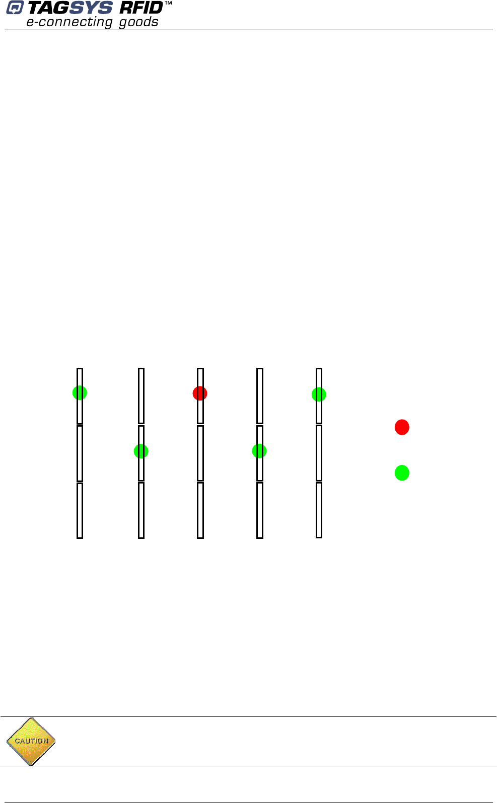
When using Hardwire synchronization, as described in 5.2.4, there is no parameter to be defined.
When using Wireless synchronization, as described in 5.2.3, you have to carefully setup each
pedestal to ensure a proper synchronization.
Synchronization parameters in wireless mode
These parameter sets are defined as follow:
If set as master, the antenna is transmitting the synchronization burst
If set as slave, the antenna is receiving the synchronization burst
The detection level for receiving the synchronization burst.
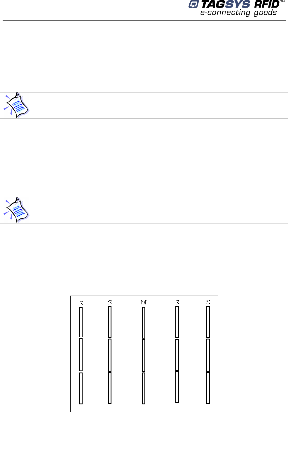
According to the number of gates installed in close proximity the following rules will apply:
If the slave pedestal is directly facing the master then the slave antenna receiving the
synchronization pattern must not face the master-transmitting antenna.
If the slave pedestal is not directly facing the master then the slave antenna receiving the
synchronization pattern must face the master-transmitting antenna.
Figure 21: Master/Slave synchronization antenna configuration
Detection level
If previous recommendations do not ensure the synchronization of all slaves then it is possible to
adjust the sensitivity of the non-synchronized slaves. You just have to adjust the detection level
until you get the required synchronization (LEDs flicking cyclically). Range detection level can be
configured between 50 up to 2000. Increasing the detection level value will reduce the sensitivity to
environmental noise.
Power
This parameter allows adjusting the power level of each pedestal. However you should not exceed
4W in order to comply with FCC and CE standard certification. It is possible to increase the power
but only to carry on tests.
CAUTION: In any case, for operational configuration this value should not exceed 4W to be
in compliant with FCC and CE rules.
M
S
S
Transmitting
Antenna
Receiving
Antenna
S
S
Library Security Pedestal 2
40/62 Revision 4.2 July 2008
The power can be lowered to avoid disturbing nearby RFID system (in such case check system
performance)
Antenna Sequence
It allows choosing antenna used by the EAS detector
Select (Top>Center>Bottom> Center) for standard operation or specifically an antenna for
diagnosis operations (Top, Center or Bottom)
Report Interval
If the same item passes through the gate several times, it will be reported only once every n
rounds (n is the number selected from the report interval section). A round duration corresponds to
Tscan, see 5.1, “Chip Configuration”.
AFI detection sensitivity
Turn it down in case too many false trigger occurs
AFI value
1 byte, enter the value in hexadecimal that matches your tag’s AFI
Alarm
Normal: pedestal will report any detected item whether or not the memory is successfully
read
Alarm on successful memory reading (Diagnosis): pedestal will only report detected items
with memory successfully read.
ISO15693 Uplink
Select Data coding mode: 1 out of 4 (26,48kbit/s), or 1 out of 256 (1,65kbits/s)
This parameter allows adjusting the transmitted data rate of each pedestal. However you should
not exceed 1.65kbits/s in order to comply with FCC standard certification. It is possible to increase
the transmitted data rate but only to carry on tests.
CAUTION: The L-SP2 pedestal has been tested to be compliant with FCC and CE rules
(with P = 4 W)
Configuration
July 2008 Revision 4.2 41/62
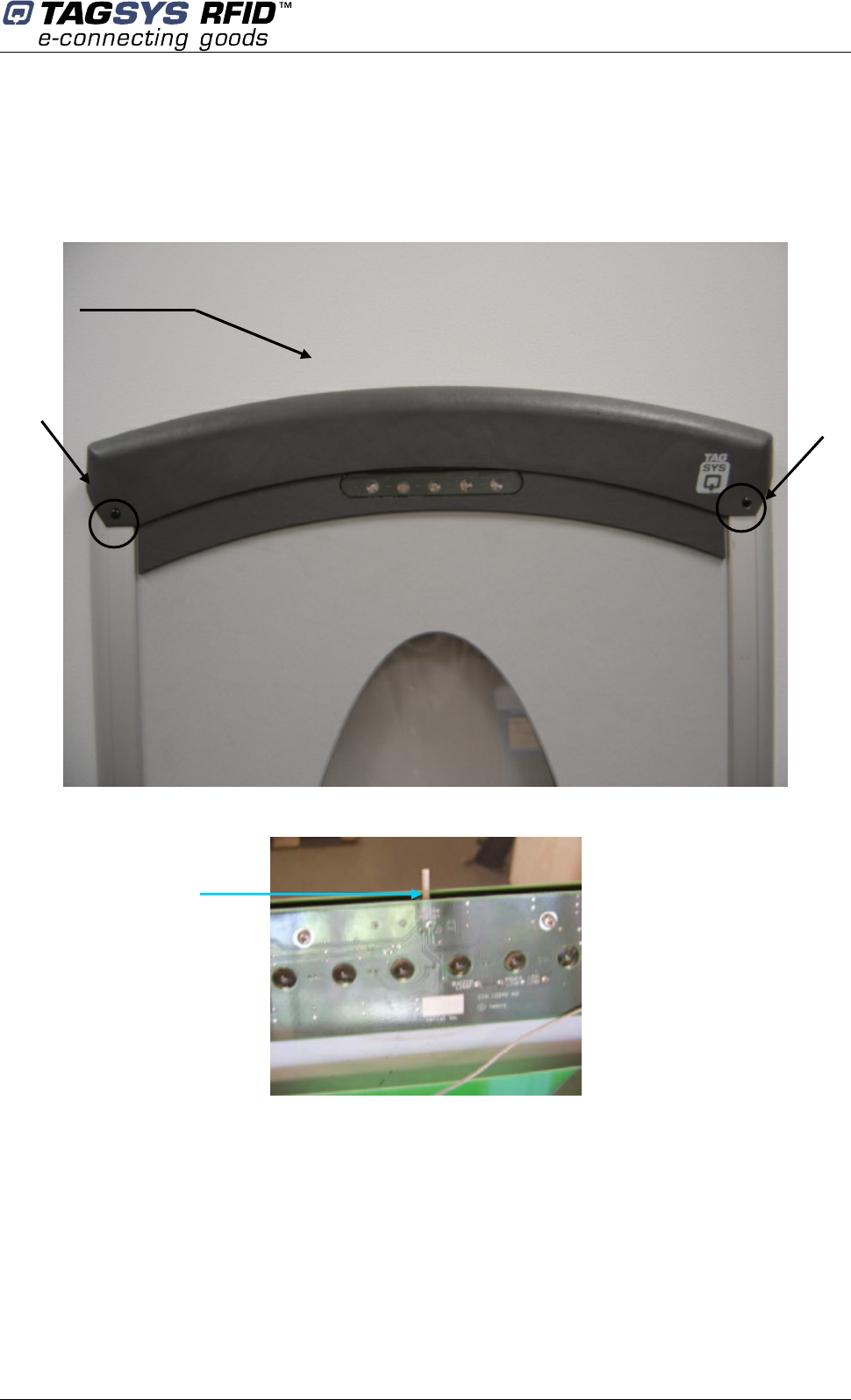
Alarm Buzzer Volume Adjustment
The alarm buzzer is located at the top of the pedestal.
To access to the buzzer potentiometer, unscrew the two screws on each side and remove the
top cover as shown in the following figures.
Figure 22: Front View
Figure 23: Alarm Potentiometer
Screw
Turn it clock wise
to decrease
vo
lume
Top Cover
Screw
Library Security Pedestal 2
42/62 Revision 4.2 July 2008
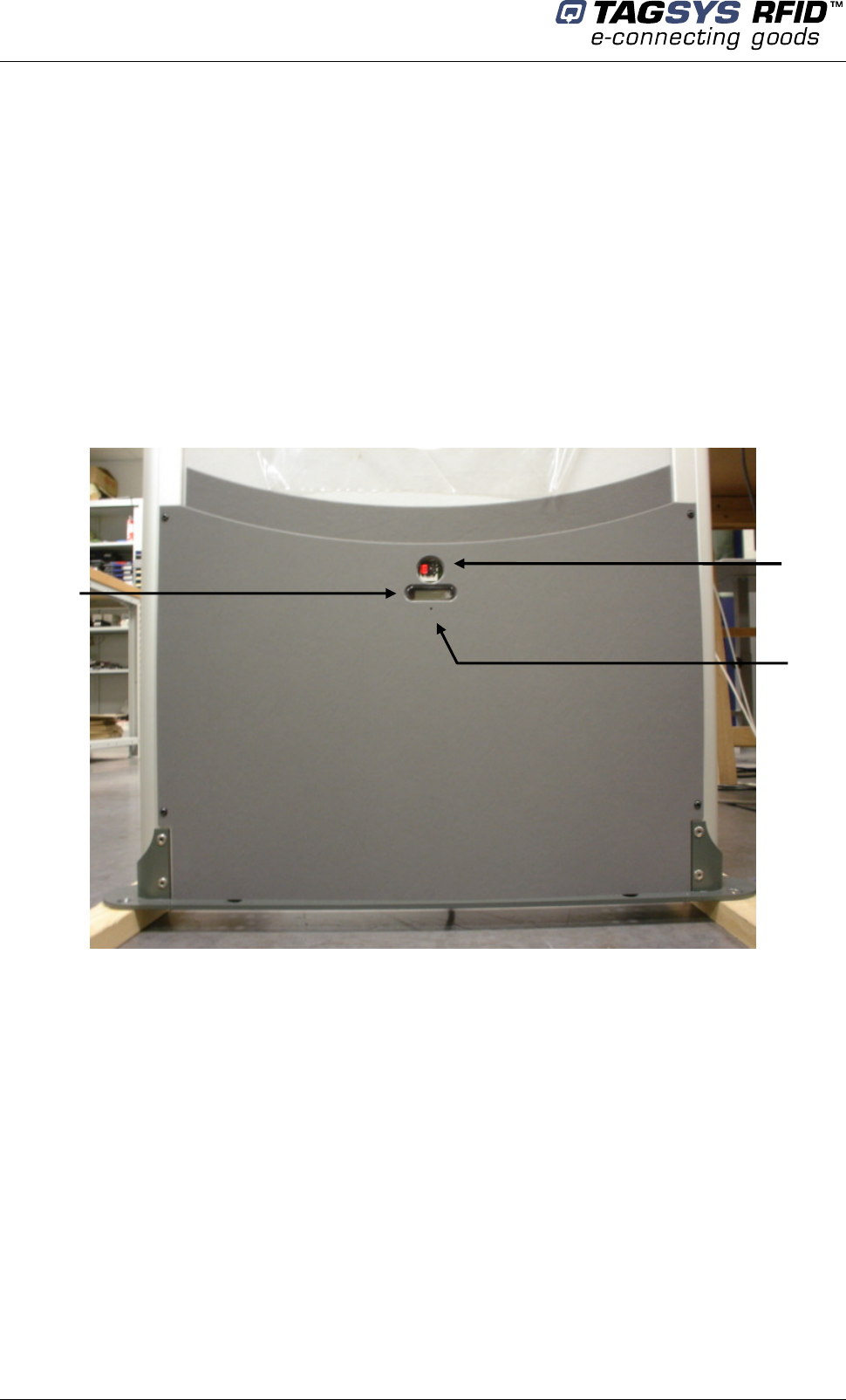
5.5 People Counter Management
The people counter information reported using the Ethernet connection is battery backed-up.
It is not the case for the LCD display. If powered off, the information displayed on the LCD display
will be reset to zero.
5.5.1 Resetting the Local People Counter
To reset the LCD display use a pointed element (for example: a paper clip). Insert it in the hole
under the display window and press (not too strong) until you get zero displayed. This will not reset
the battery backed-up counter.
Figure 24: People Counter and Sensor
5.5.2 Resetting the Remote People Counter
Connect to the L-SP2 using “L-SP2 Configuration” and click “Reset people counter”. This will
only reset the battery backed-up counter, not the LCD display.
Counter window
IR Sensor
LCD Reset
Antenna Tuning
July 2008 Revision 4.2 43/62
6 Antenna Tuning
The successful operation of the L-SP2 depends largely on:
The antenna being tuned to the correct resonance frequency (impedance),
Antenna isolation being adjusted to its optimal value.
During on-site tuning, antennas are decoupled to ensure that the minimum amount of energy is
delivered from one antenna to another.
Note that antennas are tuned before shipping and should not require any further adjustments on
site.
After the L-SP2 is completely installed, verify the antenna tuning of each pedestal to ensure that
the tuning process is necessary.
The tuning of the antennas should be verified whenever a pedestal is installed or moved.
The tuning procedure requires some knowledge of the use of equipment such as an oscilloscope,
and should therefore be carried out by a suitably qualified technician.
6.1 Required Materials
6.1.1 TAGSYS Antenna Tuning Kit (not included)
Table 3: Contents of Antenna Tuning Kit
Quantity Description
1 Antenna Tuning Device generating a 0.5 Watt, 13.56 MHz sine wave waveform
2 25-cm RG58 shielded cable with BNC connectors
1 Universal power supply 100-240 VAC to 12DC with European Pins
2 Card-size Field Strength Detector
1 Precision screwdriver to calibrate the Tuning Device
1 BNC 50-Ohm Termination
1 BNC Gender Changer
2 BNC to SMB type changer for EAS Pedestal
1 Antenna Tuning Device User's Guide
6.1.2 Oscilloscope
An oscilloscope (not supplied with the TAGSYS Antenna Tuning Kit) is necessary. It should meet
the following minimum requirements:
It is recommended that an approved TAGSYS technical representative inspect the pedestal
unit at least once per year.
The antennas should be tuned only if necessary. To determine if the tuning procedure is
required, follow the steps listed in section 6.2 “Verifying Antenna Performances”.

Library Security Pedestal 2
44/62 Revision 4.2 July 2008
100 MHz analog bandwidth (-3 dB)
5mV/division vertical resolution
10ns/div horizontal time base resolution
The measurements are taken on the sine wave and repetitive carrier signal, so when using a digital
scope, the sampling rate should be at least twice the maximum analog bandwidth.
6.1.3 Probes
At least one standard probe (not supplied with the TAGSYS Antenna Tuning Kit) will be required
for measuring a trigger signal for the normal tests. Three probes may be required for the extended
troubleshooting section.
6.2 Verifying Antenna Performances
The first step before starting the antenna tuning procedure is to verify the performance of the
pedestal antennas in order to ensure that the antennas need tuning.
Antenna performances are verified by ensuring that the L-SP2 EAS pedestals are capable of
detecting a TAGSYS RFID tag with an active EAS anti-theft bit.
1. Ensure that the L-SP2 is correctly installed and switched on.
2. Holding the TAGSYS RFID tag test card in your hand slowly move it from the top to the
bottom of the pedestal (which should take approximately ten seconds) with the TAGSYS
RFID tag approximately 450 mm (1,5 feet) from the pedestal. Verify that the LED/buzzer
board signals the detection of the TAGSYS RFID tag at the top and bottom of each antenna
(four positions, as two of them overlap).
3. Holding the TAGSYS RFID tag test card so that the TAGSYS RFID tag is horizontal (one of
the less optimum orientations), slowly move it from the top to the bottom of the pedestal
with the TAGSYS RFID tag approximately 450 mm (1,5 feet) from the pedestal. Verify that
the LED/buzzer board signals the detection of the TAGSYS RFID tag at the top and bottom
of each antenna (four positions, as two of them overlap).
If the L-SP2 pedestals detect the TAGSYS RFID tag at Steps 2 and 3, no tuning is required.
If results are questionable, antenna tuning and insulation must be checked.
6.3 Adjusting the Antenna Impedance
The impedance of the antennas can be tuned using the TAGSYS Antenna Tuning Kit or an
Impedance Analyzer. Before starting the Antenna Tuning Procedure, make sure that the antennas
require tuning (see section 6.2 “Verifying Antenna Performances”). If the antennas do not require
tuning, do not tune the antennas.
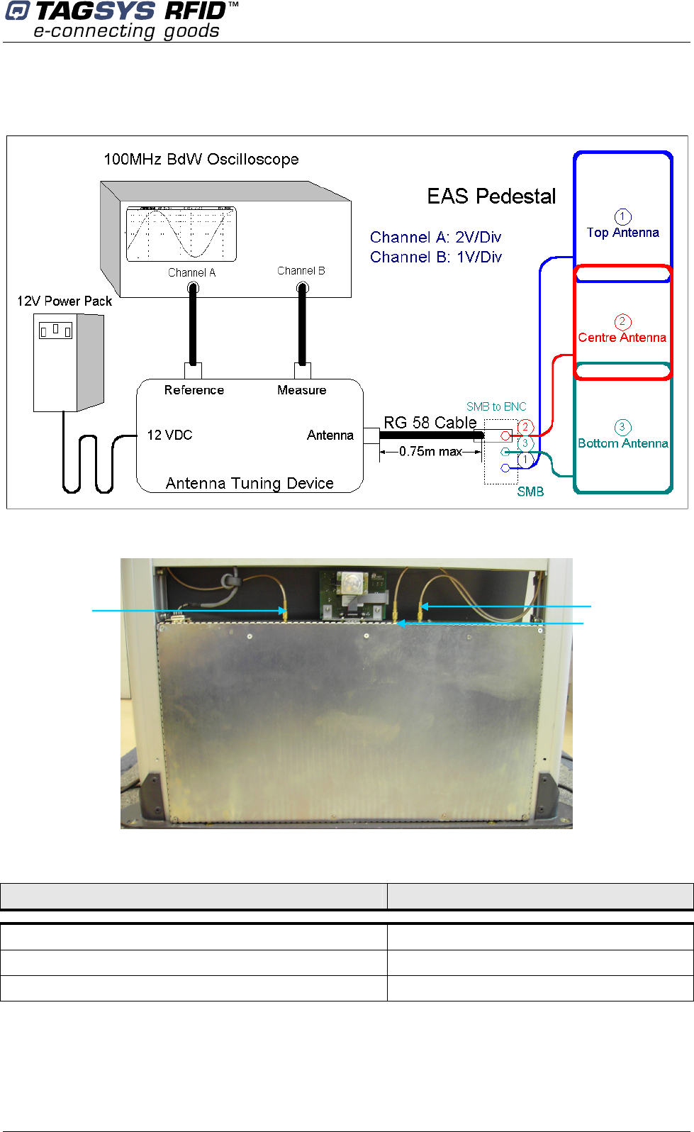
6.3.1 Using the Antenna Tuning Kit
To access to the antennas remove the top cover of the L-SP2 pedestals (See section 4.3.3
“Installing the Pedestal”) and slide out the side panels from the L-SP2 pedestals chassis then set
up the components and connections as shown in Figure 25 and Figure 26.
Antenna Tuning
July 2008 Revision 4.2 45/62
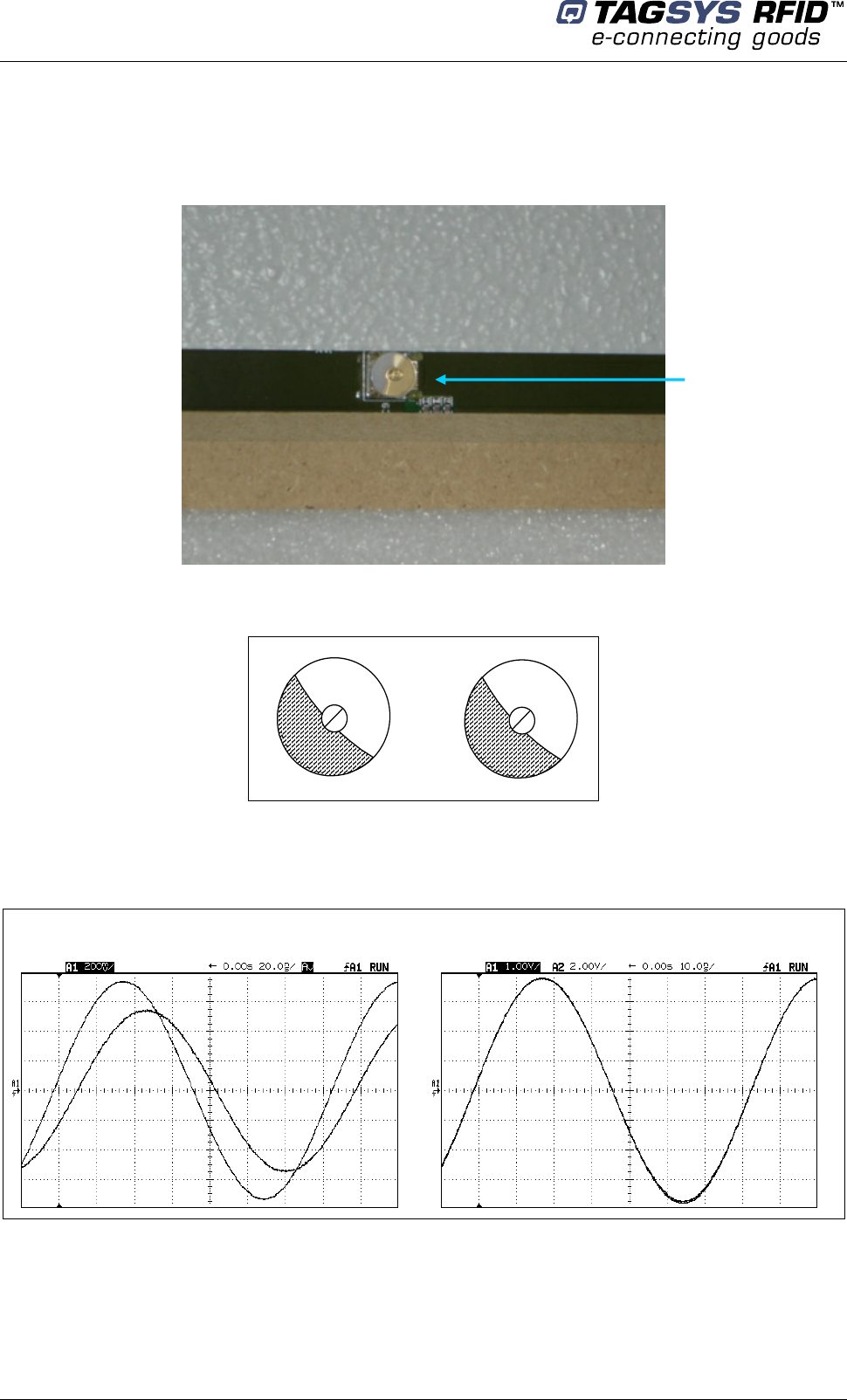
Figure 25: Antenna Tuning (Impedance)
L-SP2
Figure 26: Antenna Connection
Table 4: Oscilloscope Settings
Parameter Value
The antennas should be tuned in the following order: top, center and then bottom.
“Measure” Channel Sensitivity 1 V/Div.
“Reference” Channel Sensitivity 2 V/Div.
Time Base 20 ns/Div.
Antenna 3
Antenna 1
Antenna 2
Library Security Pedestal 2
46/62 Revision 4.2 July 2008
For the best impedance, adjust the trimmer capacitors (Figure 27) until the two curves on the
oscilloscope are exactly superimposed. For optimal performances, the two trimmer capacitors
should be set to approximately the same angle. Please see Figure 28 .
Figure 27: Trimmer Capacitor
Figure 28: Adjusting Trimmer Capacitors
The individual impedance for each antenna should be tuned to be as close as possible to:
Z0 = 50±5 + 0j±5 Ω at 13.560 MHz
Figure 29: Impedance Values using the Tuning Kit
Poor Impedance
Good Impedance
Continue the tuning process by checking the antenna isolation (see section 6.4 “Adjusting the
antenna Isolation”).
Trimmer capacitor
Antenna Tuning
July 2008 Revision 4.2 47/62
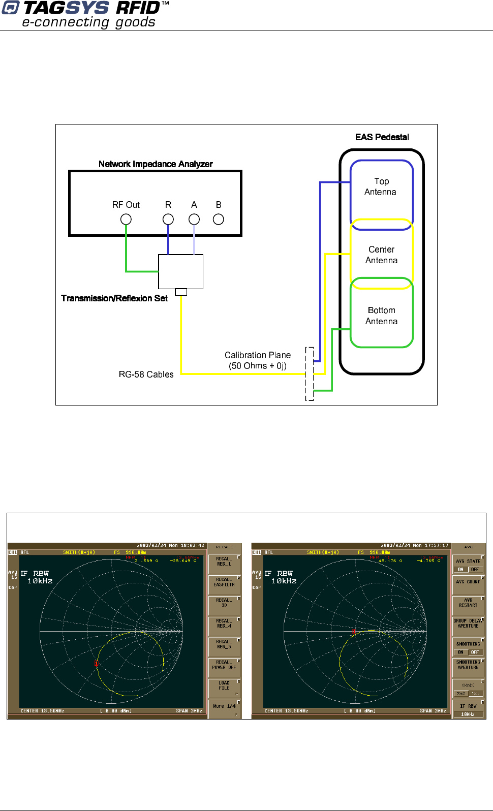
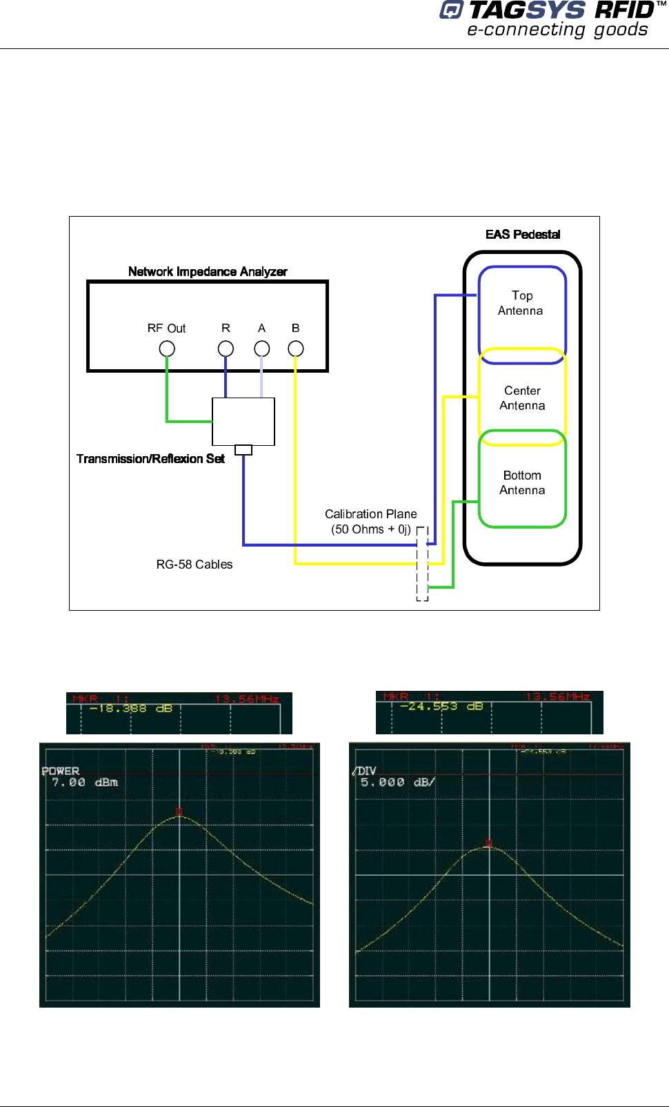
6.3.2 Using an Impedance Analyzer
If an impedance analyzer is available, connect each antenna in turn directly to the impedance
analyzer and tune the antennas in the following order: top, center and then bottom.
Figure 30: Antenna Tuning (Impedance) using an Impedance Analyzer
Adjust the trimmer capacitor (Figure 28) of each antenna for best impedance until the impedance
reaches 50±5 + 0j±5 Ω at 13.560 MHz.
Continue the tuning process by checking the antenna isolation (see section 10.4“Adjusting the
Antenna Isolation”).
Figure 31: Impedance Values using an Impedance Analyzer
Poor Impedance Good Impedance
Library Security Pedestal 2
48/62 Revision 4.2 July 2008
6.4 Adjusting the Antenna Isolation
Once each antenna is tuned for optimal impedance (see section 6.3 “Adjusting the Antenna
Impedance”), it is necessary to verify the isolation of each antenna.
Correct antenna isolation is not greater than –19-20 dB or 600-mVpp residual peak-to-peak
voltages collected on either the top or bottom antenna when the center antenna is powered by the
tuning kit sine wave carrier generator. Poor isolation is approximately –10 dB or 2 Vpp residual
peak-to-peak voltages.
Optimum isolation is obtained by sliding carefully the top or bottom antenna towards the fixed and
center antenna. When a minimum value is reached, the antenna position can be secured using the
4 screws.
The voltage is measured using an oscilloscope of at least 100-MHz analog bandwidth, 10-ns time
resolution and a 50-Ohm cable terminated at the oscilloscope input.
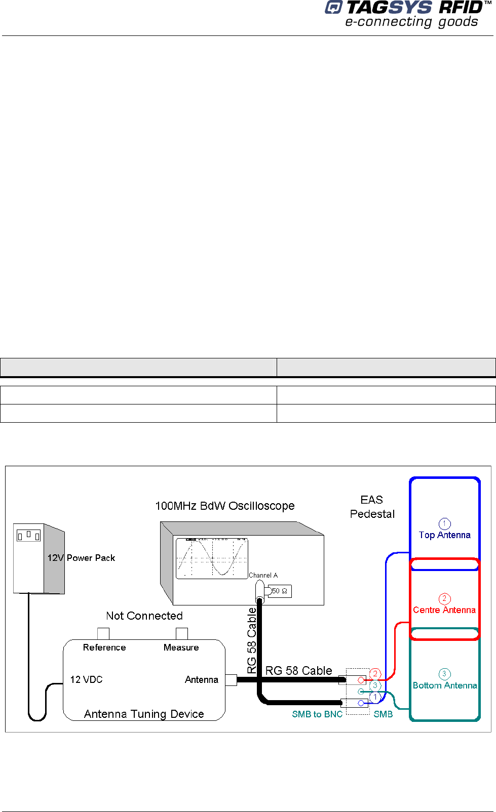
6.4.1 Using the Antenna Tuning Kit
To access to the antennas remove the top cover of the L-SP2 pedestals (See section 4.3.3
“Installing the Pedestal”) and slide out the side panels from the L-SP2 pedestals chassis then set
up the components and connections as shown in Figure 32.
Table 5: Oscilloscope Settings
Parameter Value
Figure 32: Antenna Tuning Isolation
L
-
SP2
Channel A 100 mV/Div.
Time Base 20 ns/Div.
Antenna Tuning
July 2008 Revision 4.2 49/62
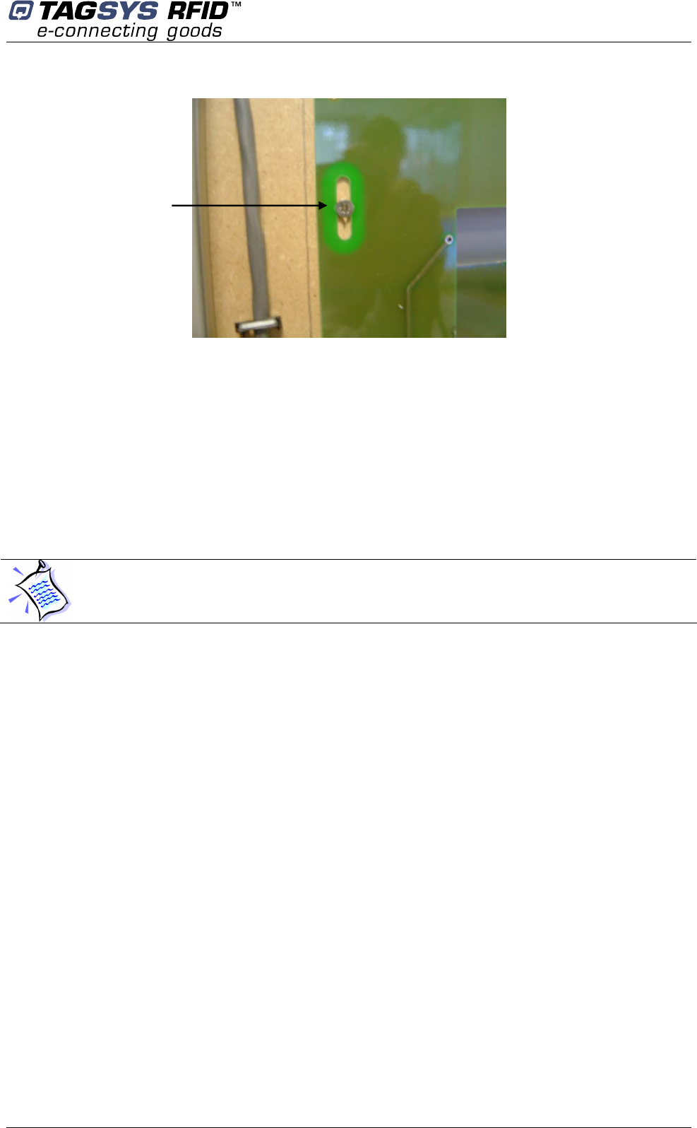
Figure 33: Antenna Adjustment Screw
The center antenna always remains fixed in position and connected to the antenna-tuning device.
The other two antennas should be slightly loosened so they can be moved with relative ease but
do not move on their own (Figure 33)
The isolation should be checked as follows:
1. Adjust the position of the bottom antenna with respect to the center antenna.
2. Adjust the vertical position of the bottom antenna so that a minimum is seen on the
oscilloscope.
3. Repeat with the top antenna.
While the top antenna is connected to the oscilloscope the bottom antenna should remain
connected to the antenna connection board, and visa versa.
The central antenna remains fixed in position and the top and bottom antennas are moved,
one at a time, to adjust the isolation.
Adjustment screw
Library Security Pedestal 2
50/62 Revision 4.2 July 2008
6.4.2 Using an Impedance Analyzer
If an Impedance Analyzer is available, perform the same procedure as described for the Antenna
Tuning Kit.
Figure 34: Antenna Tuning (Isolation) with Impedance Analyzer
Figure 35: Isolation Values using an Impedance Analyzer
Bottom and center antenna isolation Center and top antenna isolation
The effect of the metallic body on the isolation is worse with the bottom antenna

Antenna Tuning
July 2008 Revision 4.2 51/62
Note that the isolation adjustment process often requires repeating the procedure several times
between the top and center antennas and between the center and bottom antennas. This means
that it is normally more difficult to achieve good results of isolation between the center and bottom
antennas. Therefore, it is important to check and minimize the isolation between the center and
bottom antennas before moving to the top and center antennas. Typically, an isolation value equal
to or less than 600 mVpp should be obtained between the center and bottom antennas and also
between the top and center antennas.
Once the antennas have been correctly tuned for optimal impedance and isolation, it is best to
verify their synchronization with the mains power supply and the trigger threshold levels.

Library Security Pedestal 2
52/62 Revision 4.2 July 2008
7 Operation
7.1 Theory of Operation
The RF motherboard in the electronics unit produces radio frequency (RF) electromagnetic
signals that are transmitted via the antennas in each pedestal. Each antenna transmits for a short
period, receives for a short period, and is inactive for the remainder of the time.
When a TAGSYS RFID tag enters the electromagnetic field between two pedestals, some of the
RF energy (AC) is converted to DC energy and used to power the TAGSYS RFID tag’s microchip.
The remainder is used to carry the TAGSYS RFID tag’s EAS signal code back to the electronics
unit via the antennas.
7.2 Starting the System
There is no ON/OFF switch. The system operates when power is applied.
7.3 Normal Operation
No operating procedures are required. The system continues to operate as long as power is
supplied.
7.4 Shutdown
Once the system is set up and running, we recommend that all pedestals remain turned on at all
times.
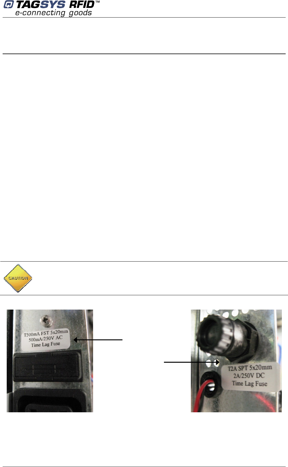
Maintenance
July 2008 Revision 4.2 53/62
8 Maintenance
8.1 Servicing the Pedestals
No regular servicing or maintenance is required, except for keeping the covers clean, and
occasionally checking the integrity of the cover seals.
It is recommended that the pedestal unit be inspected at least once per year by an approved
TAGSYS technical representative.
Refer to section 1.2 “Care and Maintenance” for general maintenance information.
8.2 Servicing the Electronics Unit
- Fuse characteristics:
On AC mains: Schurter FST, 5X20mm, Time-Lag T, H, 250VAC, 500mA
On DC supply: Schurter SPT, 5X20mm, Time-Lag T, H, 300VDC, 2A
-How to change them:
1. Fuses are inside the electronic housing located at the bottom of the L-SP2 pedestal.
2. Unscrew the 9 screws from the cover located opposed side of the counter.
3. Unscrew the head fuse and replace the fuse inside the system fuse (please see figure
below)
WARNING: AC mains 110/220V. Be sure that there is no power supply current before
carrying on the connection operation. To do so, the micro circuit-breaker must be opened.
(Figure 3)
AC Main Fuse
DC Supply Fuse
Library Security Pedestal 2
54/62 Revision 4.2 July 2008
8.3 Upgrading the DSP Firmware
DSP Firmware upgrade is carried on via the L200 Explorer software using either the RS232
cable or the Ethernet interface.
Please see L200 Explorer user's guide for more details about upgrade process.
8.4 Spare Parts
A complete list of spare parts is available upon request.
CAUTION: While upgrading the DSP Firmware, the serial cable or the Ethernet interface
MUST NOT be disconnected or the L-SP2 pedestal will not be functional anymore. In the case
this would occur, the Firmware will HAVE TO BE programmed with the L200 Explorer
software using the parallel port located in the electronic housing.
Troubleshooting
July 2008 Revision 4.2 55/62
9 Troubleshooting
The following table lists the most common problems and describes their solutions.
Table 6: Troubleshooting Table
Fault Possible Causes Solution
9.1 Sources of Interference
The following devices may cause interference with EAS systems if they are close to the pedestals:
TAGSYS RFID tag readers and programming devices
computer monitors or screens (cathode ray tubes)
radio transmitters
short-wave radios
high power music systems with D-class amplifiers
some industrial vacuum cleaners
high-frequency fluorescent lights (if very close to pedestals)
neon or halogen lights such as advertising signs
equipment using switch mode power supplies
data or power cables within 400 mm
illuminated exit signs generating noise between 80 and 100 kHz
digital phone lines (wideband noise) within 200 mm
Differential or micro circuit
breakers
Check the differential and micro
circuit breaker status
System fuse Replace fuse.
No power
Cabling fault.
Power cable fault
Check cabling and connections.
Replace any suspected faulty
cables.
Alarms missed (TAGSYS RFID
tags with theft bit ON not triggering
alarms).
Tuning fault. Check antenna tuning.
Tuning fault. Check antenna tuning.
False alarms (TAGSYS RFID tags
with theft bit OFF trigger alarms).
Nearby devices are interfering with
the pedestals. (Refer also to
section 9.1)
Switch off all or some of the
suspicious nearby devices and
check if the EAS detection
performance changes. (If it does,
check for a power problem with the
pedestal.)
CAUTION: These distances are subject to site variables. Distance may be smaller under
some conditions. Metal frames on furniture and fixture items may interfere with the EAS
system if they are too close. This is because energy from the antenna can couple into the
metallic frame and be transmitted to TAGSYS RFID tags and antennas several meters away.
Library Security Pedestal 2
56/62 Revision 4.2 July 2008
10 Technical Specifications
10.1 Mechanical Data
Parameter Value
10.2 Electrical Data
Parameter Value
10.3 RF Output Power (50Ω
ΩΩ
Ω Terminated)
Measurement values are instantaneous as the Power Burst is of very low duty cycle (0.015).
Power on for approximately 400 µs every 60 ms at 50 Hz.
Parameter P (W) P (dBm) V (V
RMS
) V (V
PP
)
Minimum Burst Power 3.6 36.6 13.4 38
Maximum Burst Power 4 36.0 14.1 40.0
10.4 I/O port
The 4 I/O ports available are used as follows:
1: OUTPUT, used to trigger the alarm + LEDs
2: OUTPUT, used to reset the People counter
3: INPUT, used by the people counter to increment the patron count
4: INPUT/OUTPUT, used for the wired synchronization
Weight Pedestal: 34 kg (75 lb)
Pedestal dimensions (H x W x D) Approx. 1777 mm x 640 mm x 80 mm (70 x 25.2 x 3.15 in) assembled
Connection for pedestal Supply power cable and Ethernet cable if available
Power supply 100/240 Volts AC, 0.5 A, 50/60 Hz
Power consumption 30 W
Conformity FCC Part 15, CE, EN 60950-1, EN 50364
Microchip compatibility TAGSYS C220, C320, C370 (NXP SLI), C370-L (NXP SLI-L), Tag-it
™HFI (Texas Instruments)
Operating temperature 0 to 50 °C (32 to 122 °F)
Storage temperature -20 to 60 °C (-4 to 140 °F)
Fuse on AC mains Schurter FST, 5X20mm, Time-Lag T, H, 250VAC, 500mA
Fuse on DC supply Schurter SPT, 5X20mm, Time-Lag T, H, 300VDC, 2A
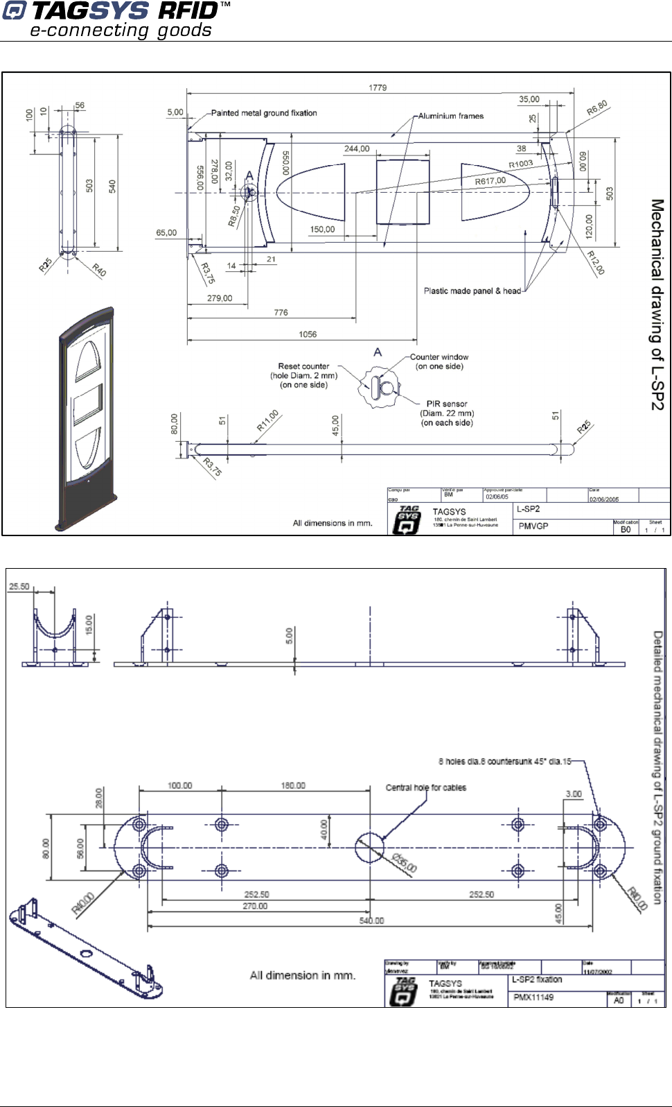
Technical Specifications
July 2008 Revision 4.2 57/62
Figure 36: Mechanical Dimensions of Pedestal Base
Figure 37: Mechanical Dimensions of Pedestal Base
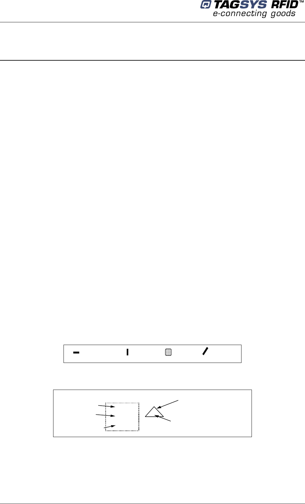
Library Security Pedestal 2
58/62 Revision 4.2 July 2008
11 Performance Test
11.1 Test Conditions
Distance between each pedestal not greater than the maximum recommended distance of 915
mm (3 ft.).
All tags used must have the theft bit set. Use of reference tag (Antenna Tuning Kit Test Card)
is strongly recommended for repeatable results.
Testing to be carried out at walking pace (maximum of 1 meter/second).
Metal, conductive materials, human hands or body must not shield tags.
All books must have tags inserted according to the 4 positions; 20-mm offset grid
recommendation.
Minimum thickness of books should be 16 mm
Each EAS system shall be installed, commissioned, tuned and operated according to TAGSYS
instructions.
11.2 Test Procedure
1. Divide the gate into 15 test zones as shown. Tip: Use masking tape to temporarily mark the
floor and pedestals.
2. Using the locked reference tag(s), walk through the gate positioning the tag in the center of
each zone.
(Start at test zone 1 and sequentially test each zone in turn)
3. If either or both pedestals sound an alarm, indicate the zone box with a check mark. If neither
sounds an alarm, indicate with a cross.
4. Repeat the test with the tag in three orientations for each zone. (Vertical, Horizontal & Facing
positions)
5. Mark the random tests with a check mark or cross inside a triangle in the appropriate test zone.
Figure 38: Tag Orientation
Horizontal Vertical Facing Random
Figure 39: Example
Additional random test
Detected
Detected
Not detected Detected
X
Zone 13
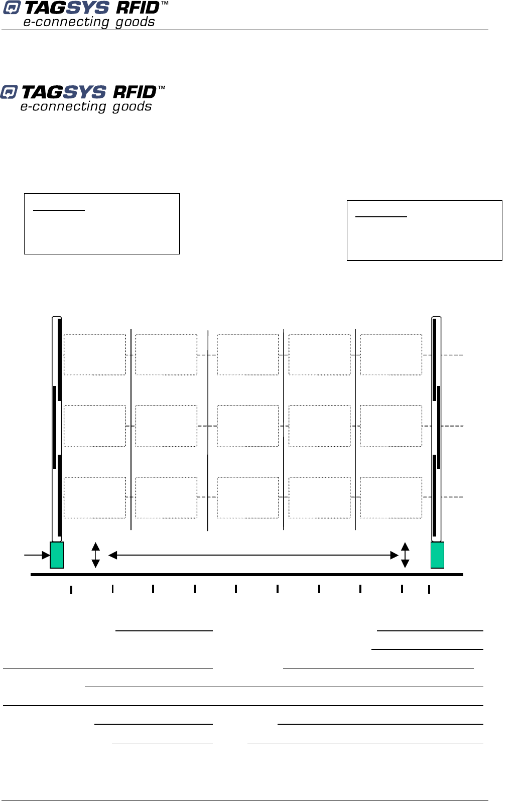
Performance Test
July 2008 Revision 4.2 59/62
L-SP2 EAS Performance Test
Library / Facility installed:
_______________________________
Location of Pedestals:
_______________________________
Specific installation notes:
_______________________________
Figure 40: Test Chart
Number of Tags used: Alarm lights working OK (Y/N)
Serial number(s) of reference Tag(s): Buzzers functioning OK (Y/N)
Test Result %
Test comments:
Tested By: Name: Company:
Signature: Date
Reader
m
1320 mm.
920 mm.
520 mm.
Floor Level
Pedestal B
S/N:
Software Version:
Zone 1
Zone 6
Zone 11 Zone 15
Zone 5
Zone 10
183mm. 366 mm. 549 mm. 732 mm.
Pedestal A
S/N:
Software Version:
Aera with no item detection
0 100
200
300
400
500
600
700 800
850

Library Security Pedestal 2
60/62 Revision 4.2 July 2008
12 Warranty Conditions
TAGSYS warrants that its L-SP2 shall comply with the functional specifications set forth herein for
a period of one year from the date of delivery to the Buyer.
This warranty is valid for the original Buyer of the Product and is not assignable or transferable to
any other party.
TAGSYS cannot be responsible in any way for, and disclaims any liability in connection with the
operation or performance of:
Any product in which the Product is incorporated;
Any equipment not supplied by TAGSYS which is attached to or used in connection with
the Product; or,
The Product with any equipment.
This warranty only applies to the Product and excludes all other equipment.
Optimal operation and performance of the Product are obtained by using TAGSYS’ readers, by
applying TAGSYS installation guidelines and by having your installation reviewed by a CIT
(Certified Integrator by TAGSYS) technical consultant.
The TAGSYS warranty does not cover the installation, maintenance or service of the Product and
is strictly limited to the replacement of Products considered as defective by TAGSYS and returned
according to the return procedure defined below; in such case, TAGSYS will, at TAGSYS’ option,
either replace every defective Product by one new Product or refund the purchase price paid by
Buyer to TAGSYS for the defective Product.
12.1 Warranty Exclusions
The following conditions are not covered under the warranty:
Defects or damages resulting from storage of the Product under conditions that do not
comply with TAGSYS specifications or normal usage.
Defects or damages resulting from use of the Product in abnormal conditions (abnormal
conditions being defined as any conditions exceeding the ones stated in the product
specifications).
Defects or damages from misuse, accident or neglect.
Defects from improper testing, operation, maintenance or installation.
Defects from alteration, modification except modifications or adjustments specifically
described in this Product reference guide, adjustment or repair, or any attempt to do any of
the foregoing, by anyone other than TAGSYS.
Any action on the product that prevents TAGSYS to perform an inspection and test of the
Product in case of a warranty claim.
Tampering with or abuse of the Product.
Any use or incorporation by the Buyer or a third party of TAGSYS’ Product into life saving
or life support devices or systems, or any related products; TAGSYS expressly excludes
any liability for such use.

Warranty Conditions
July 2008 Revision 4.2 61/62
12.2 General Provisions
This warranty sets forth the full extent of TAGSYS responsibility regarding the Product.
In any event, TAGSYS warranty is strictly limited to (at TAGSYS’ sole option) the replacement or
refund of the Products purchase price to TAGSYS, of Products considered as defective by
TAGSYS.
The remedy provided above is in lieu and to the exclusion of all other remedies, obligations or
liabilities on the part of TAGSYS for damages, whether in contract, tort or otherwise, and including
but not limited to, damages for any defects in the Products or for any injury, damage, or loss
resulting from such defects or from any work done in connection therewith or for consequential
loss, whether based upon lost goodwill, lost resale profits, impairment of other goods or arising
from claims by third parties or otherwise.
TAGSYS disclaims any explicit warranty not provided herein and any implied warranty, guaranty or
representation as to performance, quality and absence of hidden defects, and any remedy for
breach of contract, which but for this provision, might arise by implication, operation of law, custom
of trade or course of dealing, including implied warranties of merchantability and fitness for a
particular purpose.
12.3 How to Return Defective Products
The Buyer shall notify TAGSYS of the defects within 15 working days after the defects are
discovered.
Defective Products must be returned to TAGSYS after assignment by a TAGSYS Quality
Department representative of an RMA (Return Material Authorization) number. No Products shall
be returned without their proof of purchase and without the acceptance number relating to the
return procedure.
All Products must be returned in their original packaging.
All Products shall be returned with a report from the Buyer stating the complete details of the
alleged defect.
Call +33 4 91 27 57 36 for return authorization and shipping address.
If returned Products prove to be non-defective, a charge will be applied to cover TAGSYS’ analysis
cost and shipping costs.
If the warranty does not apply for returned Products (due to age, or application of a warranty
exclusion clause), a quote for replacement will be issued, and no replacement will be granted until
a valid purchase order is received. If no purchase order is received within 30 days after the date of
TAGSYS quote, TAGSYS will return the products and charge the analysis cost and shipping costs.
All replaced Products shall become the property of TAGSYS.
The Product Return Form is included on the following page. This form should accompany any
product you need to return to TAGSYS for analysis in the event of a problem.

Library Security Pedestal 2
62/62 Revision 4.2 July 2008
Product Return Form
To inform TAGSYS of this return, please email it to
RMA@tagsysrfid.com
Address to ship the product with this document attached:
TAGSYS
QUALITY DEPARTMENT
180, chemin de Saint Lambert
13821 La Penne sur Huveaune France
To inform TAGSYS of this return, please also fax it to your Customer Service Representative
+33 4 91 27 57 01
Return Procedure
The product returned will go through stringent quality controls.
A final analysis report will be sent to you as soon as possible.
Please contact your Quality Service representative for further details at
+33 4 91 27 57 36
Customer Profile:
Company: …………………………………..
Address:
……………………………………………………………
……………………………………………………………
City & State: …………………………………..
Zip Code: …………………………………..
Country: …………………………………...
Contact Name: ………………………………….
Contact e-mail: ………………………………….
Contact Phone: ………………………………….
Contact Fax: ………………………………….
Order identification:
Product Name: …………………………………..
Order Number (OEF):
Invoice Number:
………………………………….
Return Quantity:
………………………………….
Parcel Pick up:
Length: .………………………………….. Height: ……………………………………
Width: Weight: …………………………………..
Address to collect the parcel:
……………………………………………………………………………………………………………………………...
……………………………………………………………………………………………………………………………...
……………………………………………………………………………………………………………………………...
……………………………………………………………………………………………………………………………...
Contact: ……………………………………………Phone: …………………………………………….
Reason for return:
………………………………………………………………………………………………………………………..
…………………………………………………………………………………………………………………………….
…………………………………………………………………………………………………………………………….