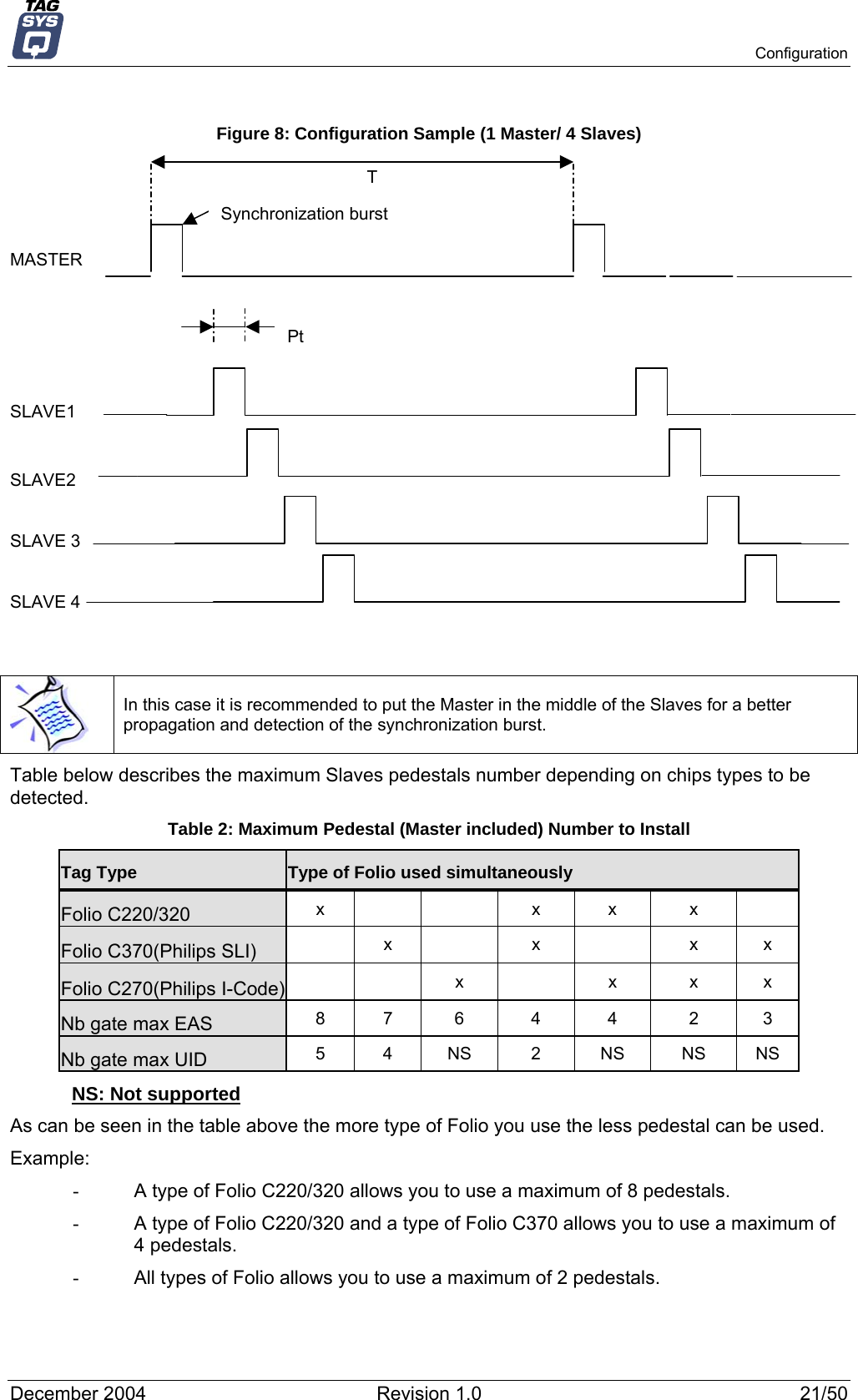
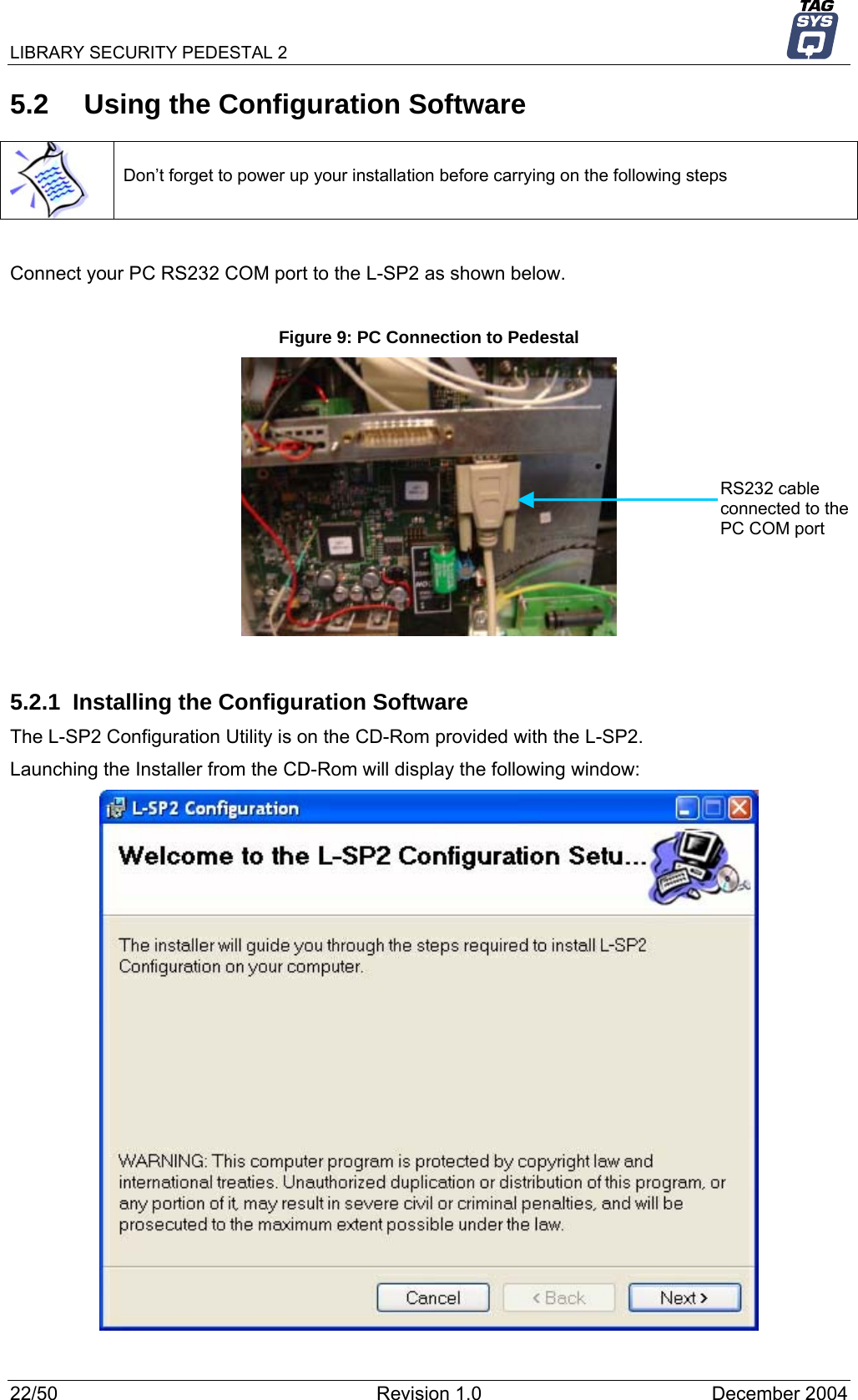
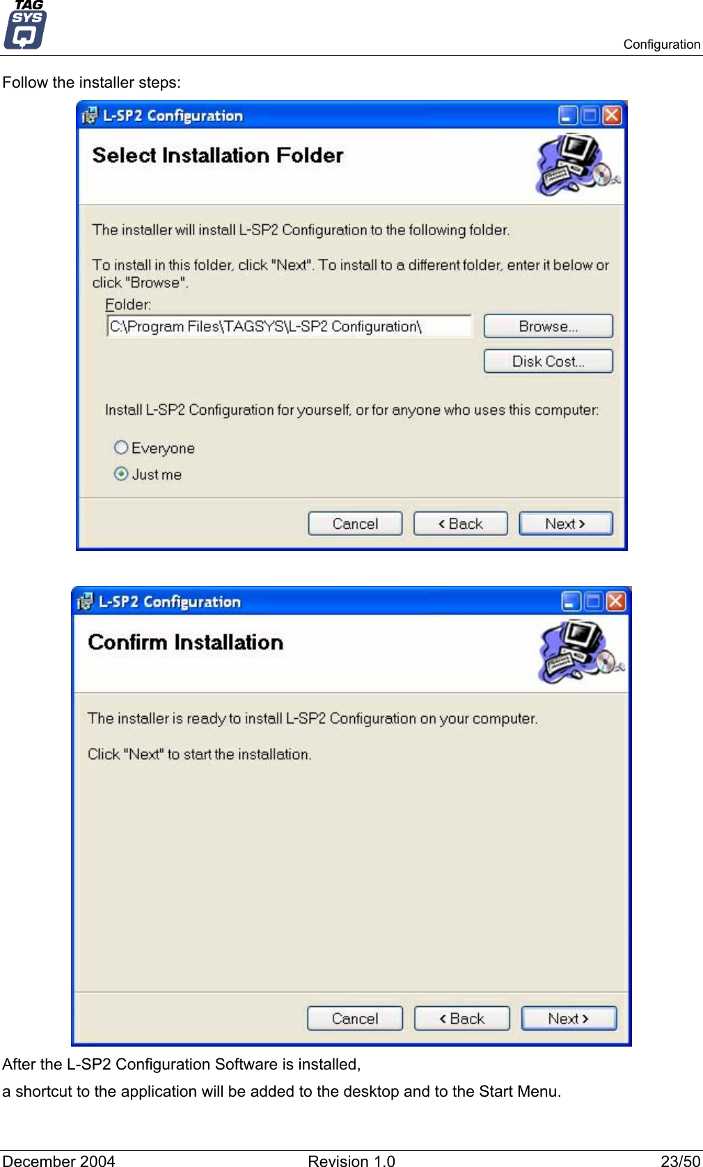
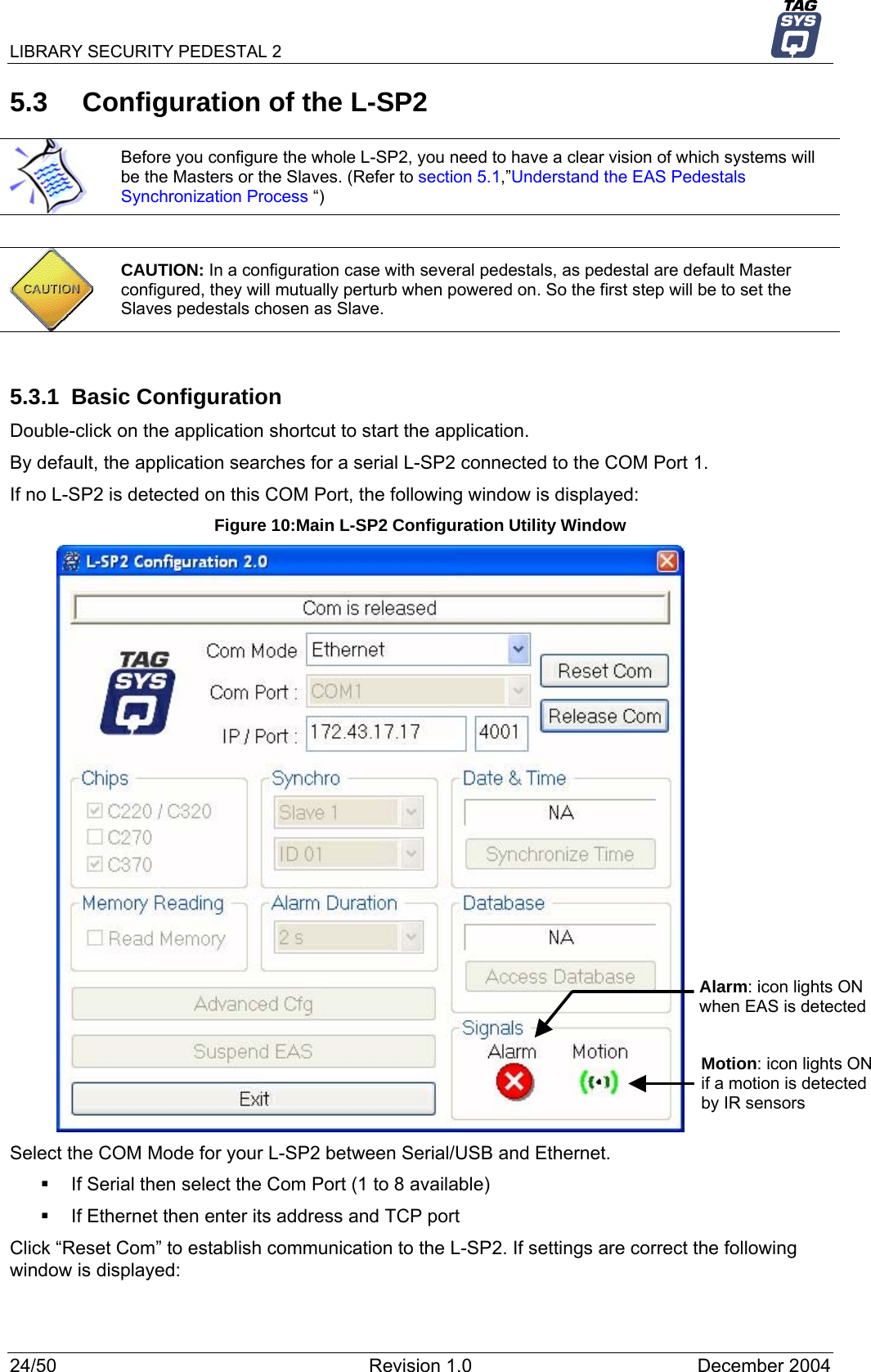
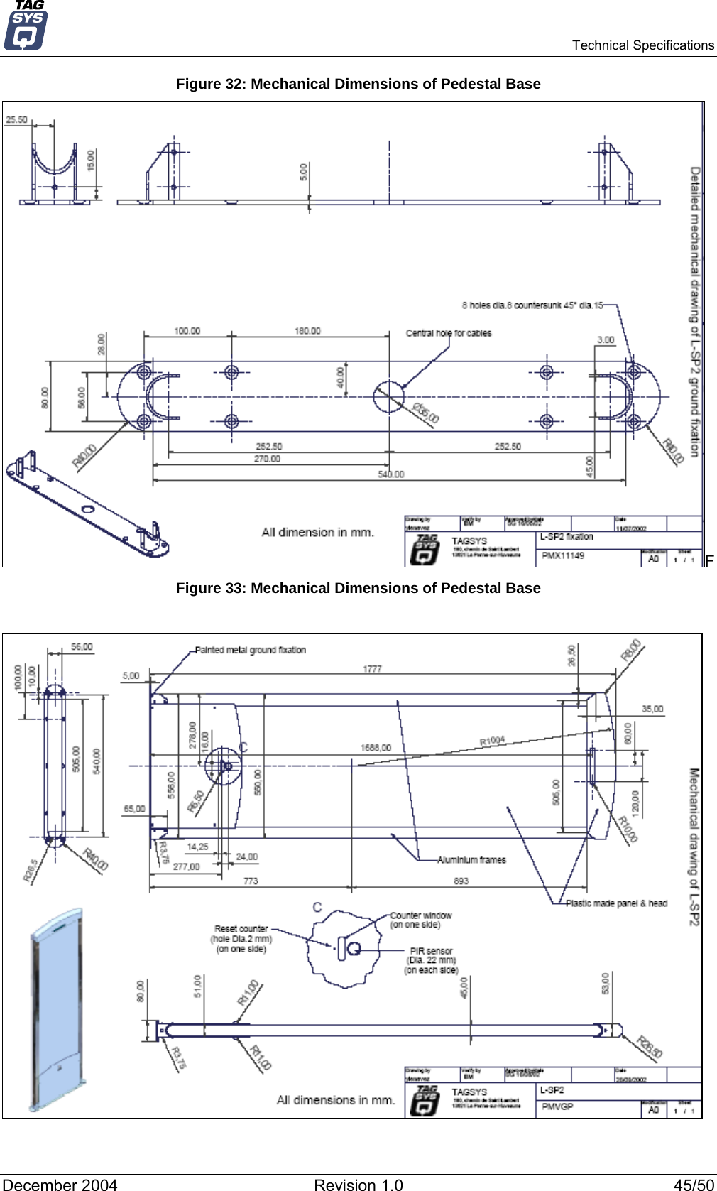
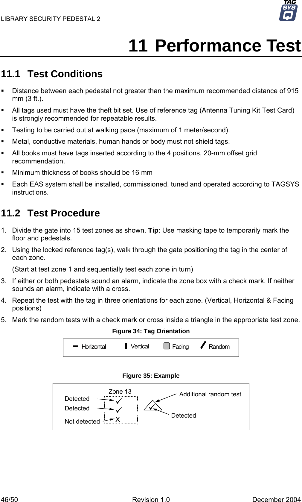
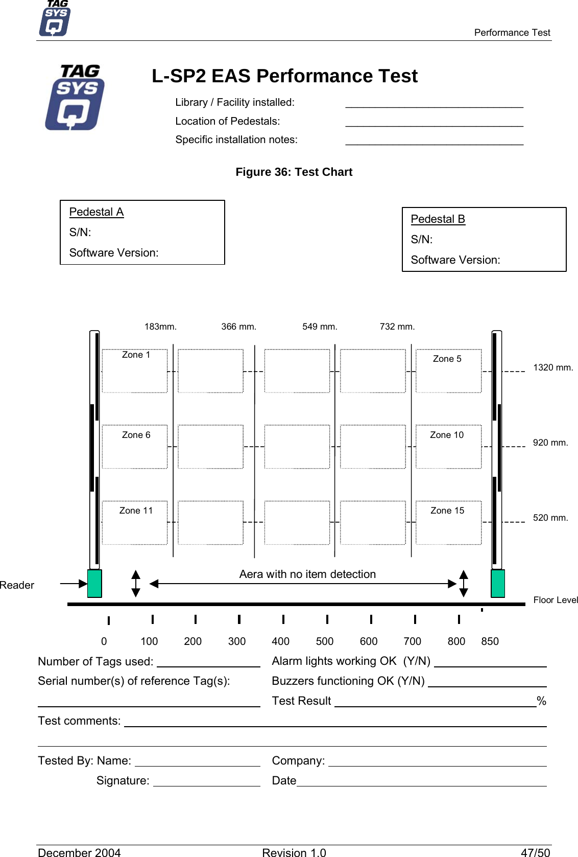
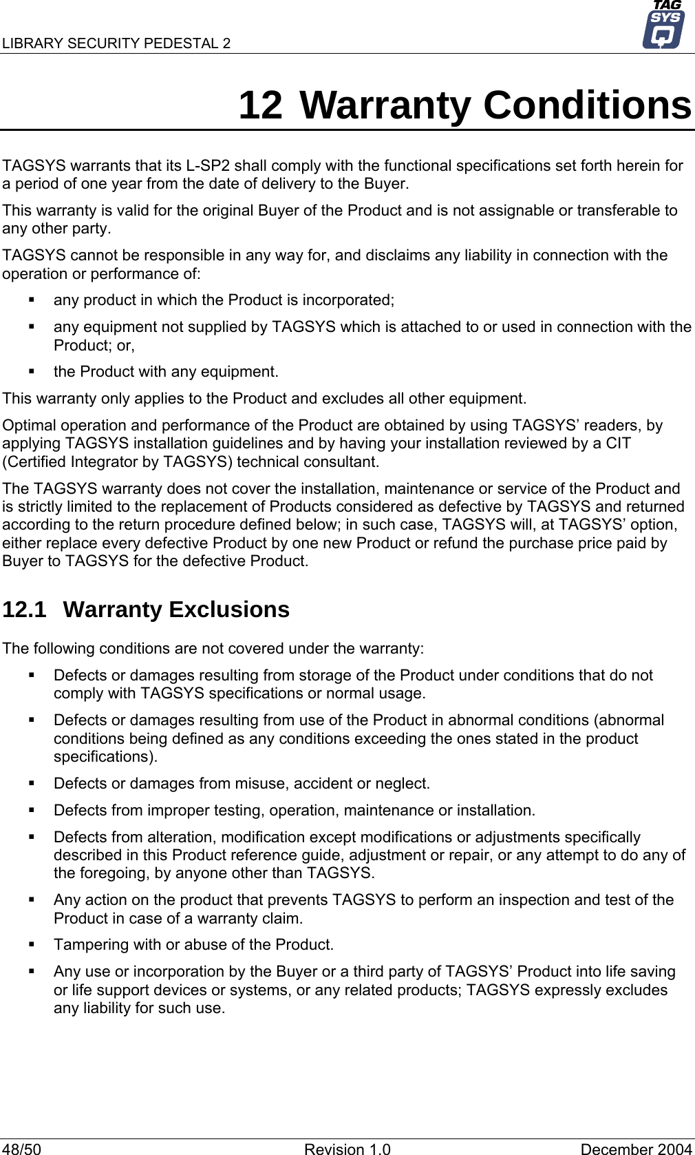
Tagsys LIBSECPEDEST2 Security Pedestal - Tag Reader User Manual LIBRARY SECURITY PEDESTAL 2

Tagsys S.A. Security Pedestal - Tag Reader LIBRARY SECURITY PEDESTAL 2

Manual

              LIBRARY SECURITY PEDESTAL 2 End User's Guide Revision 1.0             TAGSYS December 2004
LIBRARY SECURITY PEDESTAL 2     Publishing Information Disclaimer and Limitation of Liability All information herein is either public information or is the property of and owned solely by TAGSYS who shall have and keep the sole right to file patent applications or any other kind of intellectual property protection in connection with such information. Nothing herein shall be construed as implying or granting to you any rights, by license, grant or otherwise, under any intellectual and/or industrial property rights of or concerning any of TAGSYS’ information. This document can be used for informational, non-commercial, internal and personal use only provided that:    the copyright notice below, the confidentiality and proprietary legend and this full warning notice appear in all copies.   this document shall not be posted on any network computer or broadcast in any media and no modification of any part of this document shall be made. Use for any other purpose is expressly prohibited and may result in severe civil and criminal liabilities. The information contained in this document is provided “AS IS” without any warranty of any kind. Unless otherwise expressly agreed in writing, TAGSYS makes no warranty as to the value or accuracy of information contained herein. The document could include technical inaccuracies or typographical errors. Changes are periodically added to the information herein. Furthermore, TAGSYS reserves the right to make any change or improvement in the specifications data, information, and the like described herein, at any time. Therefore TAGSYS assumes no liability and is not responsible for customer applications or product or software that include TAGSYS products. TAGSYS HEREBY DISCLAIMS ALL WARRANTIES AND CONDITIONS WITH REGARD TO THE INFORMATION CONTAINED HEREIN, INCLUDING ALL IMPLIED WARRANTIES OF MERCHANTABILITY, FITNESS FOR A PARTICULAR PURPOSE, TITLE AND NON-INFRINGEMENT. IN NO EVENT SHALL TAGSYS BE LIABLE, WHETHER IN CONTRACT, TORT OR OTHERWISE, FOR ANY INDIRECT, SPECIAL OR CONSEQUENTIAL DAMAGES OR ANY DAMAGES WHATSOEVER INCLUDING BUT NOT LIMITED TO DAMAGES RESULTING FROM LOSS OF USE, DATA, PROFITS, REVENUES, OR CUSTOMERS, ARISING OUT OF OR IN CONNECTION WITH THE USE OR PERFORMANCE OF INFORMATION CONTAINED IN THIS DOCUMENT. TAGSYS does not and shall not warrant that this product/system/equipment will be resistant to all possible attacks, and shall not incur, and disclaims, any liability in this respect. Even if each product is compliant with current security standards in force on the date of their design, security mechanisms' resistance necessarily evolves according to the state-of-the-art in security and notably under the emergence of new attacks. Under no circumstances shall TAGSYS be held liable for any third party actions, and in particular in case of any successful attack against systems or equipment incorporating TAGSYS products. TAGSYS disclaims any liability with respect to security for direct, indirect, incidental or consequential damages that result from any use of its products. It is further stressed that independent testing and verification by the person using the product is particularly encouraged, especially in any application in which defective, incorrect, or insecure functioning could result in damage to persons or property, denial of service, or loss of privacy. © 2000-2004 TAGSYS. All rights reserved. TRADEMARKS. TAGSYS is a registered trademark of TAGSYS S.A, all rights reserved. ARIO, FOLIO and other TAGSYS products referenced in these pages are either trademarks or registered trademarks of TAGSYS S.A. Other products and company names mentioned in these pages may be the trademarks of their respective owners. Microsoft, Visual C++, Windows, and Windows NT are either registered trademarks or trademarks of Microsoft Corporation in the U.S.A. and/or other countries. I-Code is a registered trademark of Philips. Tag-It is a registered trademark of Texas Instruments. Printed in France. TAGSYS – 180 Chemin de St Lambert, 13821 LA PENNE SUR HUVEAUNE, France. Tel: +33 (0) 4.91.27.57.00 / fax: +33 (0) 4.91.27.57.01 Document Reference: 11492A0  2/50  Revision 1.0  December 2004
    Read This First Read This First Welcome to the TAGSYS L-SP2 Article Surveillance (EAS) system. This user’s guide is designed to help you get up and running quickly using this high-quality Radio Frequency Identification (RFID) Anti-Theft system. It describes all you need to know about how to install and use the TAGSYS EAS system and its associated applications. It provides a step-by-step guide for the following procedures:  Installation of the L-SP2 EAS anti-theft system  Configuring the system for use in your library  Personalizing your product with your own preference settings After you become familiar with the basic functions of the product, you can use the rest of this handbook as a reference for less common tasks, for maintaining your system, and also as a source of information if you have problems operating the system. This End User’s Guide is designed for all CIT (Certified Integrators by TAGSYS) and for TAGSYS Expert Network customers implementing a low-cost and high-performance RFID solution. This document does not assume any previous knowledge of Radio Frequency Identification (RFID) technology.  Conventions Symbol  Meaning  CAUTION: A note that advises users that a specific action could result in loss of data or damage the hardware. WARNING: A note that advises users that a specific action may result in physical harm.   A note that provides additional information that helps the user perform a task or obtain the best performance from the product.  Abbreviations and Acronyms AFI Application Family Identifier AON  All Or None API Application Programming Interface ASK  Amplitude Shift Keying CPU  Central Processing Unit CRC  Cyclic Redundancy Check DLL Dynamic-Link Library DPU  Digital Processing Unit DSFID  Data Storage Format Identifier DSP  Digital Signal Processor EAS  Electronic Article Surveillance December 2004  Revision 1.0  3/50
LIBRARY SECURITY PEDESTAL 2   ETX  End of Text HPI  Host Port Interface I/O Input/Output IFD Interface Device LED  Light Emitting Diode LSb   Least Significant Bit LSB   Least Significant Byte MSb   Most Significant Bit MSB   Most Significant Byte OS Operating System PC Personal Computer PCB  Printed Circuit Board RAM  Random Access Memory RF Radio Frequency RFID  Radio Frequency Identification RFU  Reserved for Future Use RPU  Radio Processing Unit RTC  Real Time Clock SAM  Security Access Module STX  Start of Text TTF  Tag Talks First TTL Transistor-Transistor Logic TTY Teletype UID Unique Identifier Glossary  Anti-Collision Tag capability making it readable while other tags are present in the RF field. Antenna An aerial that receives and/or transmits radio frequency signals. Aerials are manufactured in a variety of forms, shapes and sizes. Baud A unit of measure of data transmission speed representing the number of signal changes per second.  BNC Connector Cylindrical metal connector with a copper core that is located at the tip of a coaxial cable, and is used to connect cables together. It attaches by pushing and twisting the outer cylinder on to two locking pins. Coupler See Reader.  Data Storage Format Identifier Identifies the structure of the data stored in the TAGSYS RFID tag. Digital Signal Processor This part of the Radio Processing Unit (RPU) performs real-time TAGSYS RFID tag decoding and manages the Medio L200 configuration. 4/50  Revision 1.0  December 2004
    Read This First Dynamic-Link Library Executable routines that are stored as separate files with DLL extensions and executed only when needed by the program. Host Port Interface Interface used to access the DSP memory. IEC Connector Three-pin connector used on sockets that carry mains electricity to the computer. All PCs use a male IEC connector and mains lead with a female IEC connector. Interrogation Pulse A signal transmitted by the coupler to activate the TAGSYS RFID tag’s transponder. Monitoring Port Parallel Port granting access to the HPI. It communicates directly with the Radio Processing Unit Multi-Read See Anti-Collision Nibble Half a byte (4 bits) Packaged Reader A reader in its casing. Phase Shift Difference of phase between the 13.56 MHz field emitted by two antennas. This feature is dedicated to rotating field applications and three-dimensional volume TAGSYS RFID tag detection. Protocol A set of rules governing a particular function, such as the flow of data/information in a communication system (communication between a TAGSYS RFID tag and a reader or a reader and a PC or host computer). Radio Frequency Identification System (RFID) An automatic identification and data capture system comprising one or more readers and one or more TAGSYS RFID tags in which data transfer is achieved by means of suitable modulated inductive or radiating electromagnetic carriers. Radio Processing Unit This unit controls the main features of the Medio L200, such as the RF channels, the multiplexer and the TAGSYS RFID tag decoding. Reader Electronic system for the communication between TAGSYS RFID tags and host computers. Reader Talks First Chip protocol for exchanges between the reader and the chip, whereby the chip waits for a command from the reader to which it responds. RS-232 Electronic Industries Association (EIA) standard for serial interfaces between computers and peripherals that define the function, the electrical characteristics and the timing of signals. RS-485 Electronic Industries Association (EIA) standard for multipoint, differential data transmission. It allows multiple nodes to communicate bi-directionally over 1 or 2 twisted pairs. TAGSYS RFID tag Small, flexible, injectable tag from the 13.56 MHz TAGSYS product line. A TAGSYS RFID tag is made of a chip connected to an etched antenna. Tag See TAGSYS RFID tag. Tag Talks First Chip protocol for exchanges between the reader and the chip, whereby the tag sends information continuously, without waiting for a specific command from the reader. Transceiver A combined transmitter and receiver. Transponder A combined receiver/transmitter that automatically transmits a signal when a ‘trigger’ is received by it. The trigger is often a pulse, called an interrogation pulse. December 2004  Revision 1.0  5/50
LIBRARY SECURITY PEDESTAL 2   If you need assistance Please contact your nearest TAGSYS sales representative or the TAGSYS welcome desk at:  Telephone  +33 (0) 4 91 27 57 00  Fax:  +33 (0) 4 91 27 57 01 E-Mail:  info@tagsys.netWebsite: http://www.tagsys.net/Contact for Comments We welcome your feedback to help us provide high quality documentation.  For technical comments, please contact our welcome desk:  Telephone:  +33 (0) 4 91 27 57 00  Fax:  +33 (0) 4 91 27 57 01 E-Mail:  info@tagsys.netPlease remember to quote the Document Reference number 11492A0, your job title and your company. Quality Issues TAGSYS implements stringent quality controls at all stages of its manufacturing process. However, should you find a defect with this product, please notify your TAGSYS Quality Service representative using the dedicated Product Return Form.  Telephone:  +33 (0) 4 91 27 57 36 Fax:  +33 (0) 4 91 27 57 02  6/50  Revision 1.0  December 2004
    Read This First Table of Contents Publishing Information________________________________________________________________ 2 Disclaimer and Limitation of Liability_________________________________________________________ 2 Read This First _______________________________________________________________________ 3 Conventions _______________________________________________________________________________ 3 Abbreviations and Acronyms________________________________________________________________ 3 Glossary___________________________________________________________________________________ 4 If you need assistance ______________________________________________________________________ 6 Contact for Comments ______________________________________________________________________ 6 Quality Issues______________________________________________________________________________ 6 1 For Your Safety___________________________________________________________________ 9 1.1 General Use__________________________________________________________________________ 9 1.2 Care and Maintenance ________________________________________________________________ 9 1.3 Important Safety Information _________________________________________________________ 10 1.3.1 Operating Environment ____________________________________________________________ 10 2 Certification _____________________________________________________________________ 11 2.1 Occupational Health _________________________________________________________________ 11 2.1.1 Public Exposure __________________________________________________________________ 11 2.1.2 Employees Exposure______________________________________________________________ 11 2.2 Safety Notices_______________________________________________________________________ 11 2.3 Regulatory Notices __________________________________________________________________ 12 2.3.1 In Europe (CE and RTTE Directives) ________________________________________________ 12 2.3.2 In USA (FCC Directive) ____________________________________________________________ 13 2.3.3 In Canada _______________________________________________________________________ 13 3 System Overview ________________________________________________________________ 14 3.1 Features ____________________________________________________________________________ 14 3.2 Brief L-SP2 Description ______________________________________________________________ 14 4 Installation ______________________________________________________________________ 15 4.1 L-SP2 EAS System Components______________________________________________________ 15 4.2 L-SP2 Pedestal ______________________________________________________________________ 15 4.2.1 Tools Required ___________________________________________________________________ 15 4.2.2 Placement of Pedestals____________________________________________________________ 16 4.2.3 Installing the Pedestal _____________________________________________________________ 16 5 Configuration____________________________________________________________________ 20 5.1 Understanding the L-SP2 Synchronization Process ____________________________________ 20 5.2 Using the Configuration Software_____________________________________________________ 22 5.2.1 Installing the Configuration Software ________________________________________________ 22 5.3 Configuration of the L-SP2 ___________________________________________________________ 24 5.3.1 Basic Configuration _______________________________________________________________ 24 5.3.2 Advanced Configuration ___________________________________________________________ 28 5.4 Alarm Buzzer Volume Adjustment ____________________________________________________ 31 5.5 People Counter Reset________________________________________________________________ 32 December 2004  Revision 1.0  7/50
LIBRARY SECURITY PEDESTAL 2   6 Antenna Tuning _________________________________________________________________ 33 6.1 Required Materials___________________________________________________________________ 33 6.1.1 TAGSYS Antenna Tuning Kit (not included) __________________________________________ 33 6.1.2 Oscilloscope _____________________________________________________________________ 33 6.1.3 Probes __________________________________________________________________________ 34 6.2 Verifying Antenna Performances______________________________________________________ 34 6.3 Adjusting the Antenna Impedance ____________________________________________________ 34 6.3.1 Using the Antenna Tuning Kit_______________________________________________________ 34 6.3.2 Using an Impedance Analyzer ______________________________________________________ 36 6.4 Adjusting the Antenna Isolation ______________________________________________________ 37 6.4.1 Using the Antenna Tuning Kit_______________________________________________________ 38 6.4.2 Using an Impedance Analyzer ______________________________________________________ 39 7 Operation _______________________________________________________________________ 41 7.1 Theory of Operation _________________________________________________________________ 41 7.2 Starting the System__________________________________________________________________ 41 7.3 Normal Operation____________________________________________________________________ 41 7.4 Shutdown___________________________________________________________________________ 41 8 Maintenance_____________________________________________________________________ 42 8.1 Servicing the Pedestals ______________________________________________________________ 42 8.2 Servicing the Electronics Unit ________________________________________________________ 42 8.3 Spare Parts _________________________________________________________________________ 42 9 Troubleshooting _________________________________________________________________ 43 9.1 Sources of Interference ______________________________________________________________ 43 10 Technical Specifications________________________________________________________ 44 10.1 Mechanical Data_____________________________________________________________________ 44 10.2 Electrical Data_______________________________________________________________________ 44 10.3 RF Output Power (50Ω Terminated) ___________________________________________________ 44 11 Performance Test ______________________________________________________________ 46 11.1 Test Conditions _____________________________________________________________________ 46 11.2 Test Procedure ______________________________________________________________________ 46 12 Warranty Conditions ___________________________________________________________ 48 12.1 Warranty Exclusions_________________________________________________________________ 48 12.2 General Provisions __________________________________________________________________ 49 12.3 How to Return Defective Products ____________________________________________________ 49  8/50  Revision 1.0  December 2004
    For Your Safety 1 For Your Safety 1.1 General Use The L-SP2 is designed to be rugged and reliable and to provide years of trouble-free service. Please observe the following general tips:   Take care not to scratch the device. Keep the device clean. When working with the device, use only TAGSYS-approved accessories.    This device is not waterproof and should not be exposed to rain or moisture. Under extreme conditions, water may enter the circuitry.    Protect the device from extreme temperatures. For example, do not place the device in a windowed area where the sun may cause extreme temperatures, and keep it away from heaters and other heat sources.   Do not store or use the device in any location that is extremely dusty, damp, or wet.    Use a soft, damp cloth to clean the device. If the surface of the device becomes soiled, clean it with a soft cloth moistened with a diluted window-cleaning solution. 1.2  Care and Maintenance This device is a product of superior design and should be handled with care. The suggestions below will further increase the lifetime of this device.    Keep the device and all parts and accessories out of the reach of small children.   Keep the device dry. Precipitation, humidity and liquids contain minerals that will corrode electronic circuits.   Do not use or store the device in dusty, dirty areas. Its moving parts can be damaged.   Do not store in hot areas. High temperatures can shorten the life of electronic devices, damage batteries and warp or melt certain plastics.   Do not store in cold areas. When the device warms up (to its normal temperature), moisture can form inside the device, which may damage electronic circuit boards.   Do not attempt to open the device. Non-professional handling of the device may damage it.   Handle the device with care. Shocks may break internal circuit boards.   Do not clean the device with harsh chemicals, cleaning solvents or strong detergents. Gently wipe the device with a soft cloth slightly dampened in a mild soap-and-water solution.   Do not paint the device. Paint may clog the device’s moving parts and prevent proper operation. Paint with metallic contents may limit device performances.   If the device or any accessory are not working properly, take it to your nearest qualified TAGSYS representative.  December 2004  Revision 1.0  9/50
LIBRARY SECURITY PEDESTAL 2   1.3  Important Safety Information 1.3.1 Operating Environment When connecting the device or any accessory to another device, read its user’s guide for detailed safety instructions. Do not connect incompatible products. As with all RF equipment, users are advised that the equipment should only be used in its normal operating position. 10/50  Revision 1.0  December 2004
  Certification 2 Certification 2.1  Occupational Health  TAGSYS L-SP2 EAS System has been designed and tested to be in conformity with the European Standard EN 50364 “Limitation of human exposure to electromagnetic fields from devices used in Electronic Article Surveillance (EAS), Radio Frequency Identification (RFID) and similar applications” in conjunction with the European Standard EN 50357 describing how to evaluate the exposure level. 2.1.1 Public Exposure The EAS systems are only planned for transitory use by the public.   Que les bibliothécaires mettent en place les mesures de surveillances aux portes pour exclure la permanence d’une personne entre elles.  2.1.2 Employees Exposure The operators are located apart from the principal detection zone. So ils ne court aucun risque, Les travaux les plus avncés de l’EN + travaux  en cours  + description de la norme + remarques données par le labo. (Please see section 4.2.2, “Placement of Pedestals”)   Regarding European Standard EN 50364 and because the EAS system expose in a transitory way people who cross it, it is recommended not to wait in the middle of the system.   For servicing operations it is recommended to deactivate the EAS system. 2.2 Safety Notices The L-SP2 is also tested to be in conformity with the EN standard 60950-1: “ Information Technology Equipment Safety” It is the responsibility of the CIT (Certified Integrators by TAGSYS) to install the L-SP2 as described in TAGSYS Product Manuals or TAGSYS Documentation and with the appropriate antennas. Modification of any TAGSYS Library System is prohibited without the written consent of TAGSYS. Unauthorized modifications may void the conformity of the equipment to safety specifications and will void the TAGSYS warranty. December 2004  Revision 1.0  11/50
LIBRARY SECURITY PEDESTAL 2   2.3 Regulatory Notices An RFID system typically composed of an RF emission device such as the L-SP2 connected to an antenna is subject to national regulations that may differ by country. One important item to consider is the maximum permissible magnetic field intensity at a distance of 10 meters from the antenna that must not exceed 42 dBµA/m in Europe and 38 dBµA/m in US. The L-SP2 meets these limits.  2.3.1  In Europe (CE and RTTE Directives)  The L-SP2 complies (CE Declaration of Conformity granted) with the European EMC directive. The L-SP2 complies with the requirements of the Telecommunication Terminal Equipment Act (FTEG) and the RTTE Directive 1995/5/EC. It is the responsibility of the TAGSYS Reseller to install the L-SP2 as described in this User’s Guide or TAGSYS Documentation. Any modification of the L-SP2 is prohibited without the written consent of TAGSYS. Unauthorized modifications may void the conformity of the equipment to CE and RTTE Directives and will void the TAGSYS warranty.   CAUTION:  It is the responsibility of the CIT (Certified Integrators by TAGSYS) to install the L-SP2 as described in this Reference Guide or in TAGSYS Documentation. If a L-SP2 is further integrated in a different product, it is the responsibility of the manufacturer of this complementary product to obtain the required approvals for this product.  12/50  Revision 1.0  December 2004
  Certification  2.3.2  In USA (FCC Directive) L-SP2 WARNING TO USERS IN THE UNITED STATES FEDERAL COMMUNICATIONS COMMISSION (FCC) RADIO INTERFERENCE STATEMENT 47 CFR Section 15.105(b)  This equipment has been tested and found to comply with the limits for a Class B digital device, pursuant to Part 15 of the FCC Rules. These limits are designed to provide reasonable protection against harmful interference in a residential installation. This equipment generates, uses and can radiate radio frequency energy and if not installed and used in accordance with the instructions may cause harmful interference to radio communications. However, there is no guarantee that interference will not occur in a particular installation. If this equipment does cause harmful interference to radio or television reception, which can be determined by turning the equipment off and on, the user is encouraged to try to correct the interference by one or more of the following measures:  ▪   Reorient or relocate the receiving antenna. ▪   Increase the separation between the equipment and receiver. ▪   Connect the equipment into an outlet on a circuit different to that to which the receiver is connected. ▪   Consult the dealer or an experienced radio/TV technician for help. NO UNAUTHORIZED MODIFICATIONS 47 CFR Section 15.21 CAUTION: This equipment may not be modified, altered, or changed in any way without signed written permission from TAGSYS SA. Unauthorized modification may void the equipment authorization from the FCC and will void the TAGSYS warranty.  ANTENNA REQUIREMENT 47 CFR Section 15.203 CAUTION: This equipment must be professionally installed. The installer shall be responsible for ensuring that the proper antenna is employed so that the limits in this part are not exceeded. Non-professional installation or installation of the equipment with an improper antenna may void the equipment authorization from the FCC and will void the TAGSYS warranty. The L-SP2 has been designed to comply with Part 15 of the FCC Rules. Operation is subject to the following two conditions: (1) The system devices may not cause harmful interference, and (2) The library system devices must accept any interference received, including interference that may cause undesired operation. 2.3.3 In Canada Cet appareil numérique de la classe B respecte toutes les exigences du Règlement sur le matériel brouilleur du Canada. This Class B digital apparatus meets all requirements of the Canadian Interference-Causing Equipment Regulations. December 2004  Revision 1.0  13/50
LIBRARY SECURITY PEDESTAL 2   3 System Overview 3.1 Features Being a standalone solution, TAGSYS Security Gates do not need to be linked to the library database, and can still operate when the Integrated Library System (ILS) is down or under maintenance. The security gate does not require additional equipment to operate. The L-SP2 pedestal includes new functionalities as: -  multi-protocol features which makes it  compatible with C220, C320, C270 (Philips I-code), C370 (Philips SLI) chips -  one block system electronic embedded into the pedestal -  mechanical compatibility with Smarto L122 EAS system -  one people counter This is a low-cost security system as it only requires a single RFID tag for both anti-theft and identification purposes. 3.2  Brief L-SP2 Description The components of the L-SP2 EAS system are contained within the L-SP2 pedestal. At least two pedestals are required for each EAS gate. A set of pedestals is known as a gate and may consist of several pedestals Please see section 4, “ Installation “ for more information. The  L-SP2 are built in a one frame: -  the electronics unit located on the bottom of the pedestal which manage the whole system A L-SP2 Electronics unit is used to control each pedestal. This electronics unit generates the RF signal transmitted by the antennas and picks up the reply from the TAGSYS RFID tag. If a TAGSYS RFID tag with an active theft bit (ON) is detected, the electronics unit will activate the alarm of the LED/buzzer board on the pedestal. -  These antennas are sensitive receivers used to detect the status of the theft bit in the TAGSYS RFID tag as it passes through the EAS gate. -  a warning visual and audible device (LED/Buzzer board) -  a  people counter equipped with an IR sensor having two functionalities: 1.  detect crossing people (counter) 2.  to be able to limit the alarm release only if a person is detected (this functionality can be deactivated using the L-SP2 Configuration Utility) To operate, the L-SP2 will only need a power supply cable.  14/50  Revision 1.0  December 2004
  Installation 4 Installation 4.1  L-SP2 EAS System Components The components included in the L-SP2 EAS System package are listed in Table 1. The entire kit is delivered in a box as shown in Figure 1. Table 1: L-SP2 EAS System Components Quantity  Description 1  L-SP2 Pedestal 8  40 mm Philips-head, countersunk screws with a diameter of 6 mm  8  8 mm plastic cement plugs 1  L-SP2 EAS System CD-ROM  1  RS 232 cable Figure 1: Delivery of L-SP2 EAS System Components  4.2 L-SP2 Pedestal  CAUTION: This equipment is intended for indoor use only under the conditions described in this document. Should it be used outside these conditions cannot be guaranteed, and is not recommended. Please read section 1“ For Your Safety “ before installation or use. 4.2.1 Tools Required The following tools are required during installation :    Tape measure    Square   Drill with 4 mm, 8-mm and 19-mm bits   Philips-head screwdriver   Level    December 2004  Revision 1.0  15/50
LIBRARY SECURITY PEDESTAL 2   4.2.2  Placement of Pedestals   CAUTION: In the case of several pedestal row installation then it is significant that all L-SP2 being  positioned in the same direction (the people counter of each looking forward the same direction) Pedestals must be mounted between 800 and 915 mm apart (center to center) for maximum reliable performance. There should be at least one pair of pedestals at each entrance/exit point of the library. There should be a pedestal at each edge of the entrance, and a clear space of at least 500 mm around the edge of the pedestals to ensure that the antennas are not detuned ( ). This clear space must not contain any metallic objects, but may contain some substrates such as non-metallic/non-conductive building materials such as wood, glass, chipboards and plasterboards.   There should be a distance of at least 2.5 m. (~ 8 ft.) between the pedestals and a circulation desk or other RFID station. There should be a distance of at least 9 m. (~ 30 ft.) between pedestals with the same synchronization ID. 4.2.3 Installing the Pedestal The L-SP2 pedestal is mechanically compatible with the Smarto L122 Pedestal. After having defined the location of the pedestals, refer to the mechanical drawing of the pedestal mounting diagram (Figure 2). The pedestal is fastened to the floor using screws that are strong enough to support the weight of an average adult falling against the pedestal.  Figure 2: Pedestal Mountings  1.  Identify and mark the location of the holes to be drilled for mounting the pedestal to the ground. The use of a tape measure and a square is recommended. 2.  Drill the cable access and mounting holes according to the type of ground surface: a.  Wood floor: Drill eight holes with a diameter of 4 mm for the mounting screws and one hole with a diameter of 19 mm for the cable access.  b.  Cement floor: Drill eight holes with a diameter of 8 mm for the cement floor plugs and one hole with a diameter of 19 mm for the cable access. It may be necessary to provide a groove for the power supply cable connected to the L-SP2 Electronics Unit. Insert the concrete floor plugs into the mounting holes.   CAUTION: Always use a protective sleeve for main power cable which match to the non-inflammability standard. Main power cable must be a 3 wire (line, neutral and earth), multi stranded copper wire, 0.5 mm²/ 3A) 16/50  Revision 1.0  December 2004
  Installation  3.  Remove the pedestal from the box. 4.  Place the cover face to you with the display counter on the other side then remove the 4 screws  from the  bottom cover. Figure 3: L-SP2 Bottom  The 4 screws   5.  Remove the plastic cover and then un-clip the metallic cover of the electronics box. Then pull out the opposed cover which will come together with the opposite metallic cover.  Figure 4: Open Pedestal Bottom  Cable access hole Ac main PCB  6.  Place the pedestal base over the cable access over the mounting holes.  CAUTION : AC mains 110/220V. Be sure power supply cable is not connected to the main for the following operations.  December 2004  Revision 1.0  17/50
LIBRARY SECURITY PEDESTAL 2   7. Insert the power supply cable into the Electronics Unit through the cable access hole as shown above. Check that the cable is correctly positioned and that there are no friction points.  8.  Insert and fasten the screws in the mounting holes according to the type of ground surface: a.  Wood floor: Insert the screws directly into the mounting holes and tighten the screws in place.  b.  Concrete floor: Insert the screws into the concrete floor plugs and tighten the screws in place.  CAUTION: When tightening the screws in place, first tighten the screws in place ¾ of the way. Once all screws are in place, then tighten each screw progressively, one after each other to ensure that the floor bracket is solidly fixed into place and completely vertically aligned. The use of a level may be required.  9.  Unplug the connector block. Strip the 3 wires from the power supply cable and connect them to the connector block provided according to the instructions below as indicated on the PCB. Please see figure below. Figure 5: Connector Block  System FuseLine  Neutral Earth Connector Block   CAUTION: Fix the main power cable using the specific clip as shown in Figure 6. Figure 6: Power Cable Fixing 18/50  Revision 1.0  December 2004
  Installation  Clip 10. At this stage, the L-SP2 must be configured before reassembling the bottom pedestal. To carry on configuration operations (Please see section 5,”Configuration«).   We recommend you to install the whole pedestals before carry on configuration operations 11. Power up the system before starting configuration. 12. Once the configuration has been carried on, the L-SP2 can be reassemble following steps 4 and 5 in reverse order. December 2004  Revision 1.0  19/50
LIBRARY SECURITY PEDESTAL 2   5 Configuration All configuration operations of L-SP2 systems are carried on with the L-SP2 Configuration Utility. 5.1  Understanding the L-SP2 Synchronization Process  To determine the status of each EAS anti-theft bit, each pedestal generates a short but substantial radio frequency burst whose energy can interfere with other nearby EAS pedestals. To prevent this interference, each pedestal must have a different synchronization setting than all the others in the near vicinity so that only one antenna is generating an RF burst at any given time.  In the L-SP2, there is no interconnection between pedestals, so the synchronizing is carried on by radio frequency. •  Only one device is defined to be the master who emits a synchronization burst. •  The other devices are configured as slaves and synchronize themselves on the master’s burst and process their EAS detection task according to their assigned slave ID. Diagram below describe some Master/Slaves configurations.   Default configuration of the L-SP2 is set to Master.  Figure 7: Minimum Configuration (1 Master / 1 Slave)     MASTER   SLAVE1 T Pt Synchronization burst      Synchronization burst: start burst to synchronize the gates (Period of T ms) Processing time (Pt): depend on number and chips types to be detected 20/50  Revision 1.0  December 2004
  Configuration  Figure 8: Configuration Sample (1 Master/ 4 Slaves)  Pt Synchronization burst T   MASTER      SLAVE1  SLAVE2  SLAVE 3  SLAVE 4    In this case it is recommended to put the Master in the middle of the Slaves for a better propagation and detection of the synchronization burst. Table below describes the maximum Slaves pedestals number depending on chips types to be detected. Table 2: Maximum Pedestal (Master included) Number to Install Tag Type Type of Folio used simultaneously Folio C220/320 x     x x x  Folio C370(Philips SLI)  x  x  x x Folio C270(Philips I-Code)   x  x x x Nb gate max EAS 8 7 6 4 4 2 3 Nb gate max UID  5 4 NS 2 NS NS NS NS: Not supported As can be seen in the table above the more type of Folio you use the less pedestal can be used. Example:  -  A type of Folio C220/320 allows you to use a maximum of 8 pedestals. -  A type of Folio C220/320 and a type of Folio C370 allows you to use a maximum of 4 pedestals. -  All types of Folio allows you to use a maximum of 2 pedestals. December 2004  Revision 1.0  21/50
LIBRARY SECURITY PEDESTAL 2   5.2  Using the Configuration Software  Don’t forget to power up your installation before carrying on the following steps   Connect your PC RS232 COM port to the L-SP2 as shown below.  Figure 9: PC Connection to Pedestal  RS232 cable connected to the PC COM port  5.2.1 Installing the Configuration Software The L-SP2 Configuration Utility is on the CD-Rom provided with the L-SP2. Launching the Installer from the CD-Rom will display the following window:  22/50  Revision 1.0  December 2004
  Configuration Follow the installer steps:    After the L-SP2 Configuration Software is installed, a shortcut to the application will be added to the desktop and to the Start Menu. December 2004  Revision 1.0  23/50
LIBRARY SECURITY PEDESTAL 2   5.3  Configuration of the L-SP2  Before you configure the whole L-SP2, you need to have a clear vision of which systems will be the Masters or the Slaves. (Refer to section 5.1,”Understand the EAS Pedestals Synchronization Process “)   CAUTION: In a configuration case with several pedestals, as pedestal are default Master configured, they will mutually perturb when powered on. So the first step will be to set the Slaves pedestals chosen as Slave.  5.3.1 Basic Configuration Double-click on the application shortcut to start the application. By default, the application searches for a serial L-SP2 connected to the COM Port 1. If no L-SP2 is detected on this COM Port, the following window is displayed: Figure 10:Main L-SP2 Configuration Utility Window            Alarm: icon lights ON when EAS is detected Motion: icon lights ON if a motion is detected by IR sensors Select the COM Mode for your L-SP2 between Serial/USB and Ethernet.   If Serial then select the Com Port (1 to 8 available)   If Ethernet then enter its address and TCP port Click “Reset Com” to establish communication to the L-SP2. If settings are correct the following window is displayed: 24/50  Revision 1.0  December 2004
  Configuration   Figure 11: Example of Configuration    Once the communication is set and the system identified, the software displays the current configuration recorded in the L-SP2.  Reset Com Reset the communication to the gate regarding Com Mode, Com Port and IP/Port settings. Release Com Release  the communication to the gate. (Get back to Figure 10 ) Chips Select the chips to be decoded More chips you select less pedestal can be synchronized. Please refer to Table 2: Maximum Pedestal (Master included) Number to Install    December 2004  Revision 1.0  25/50
LIBRARY SECURITY PEDESTAL 2   Memory Reading When selected, the L-SP2 will try to read memory of items (with EAS activated) passing through the gate. Synchro Select whether the pedestal is to be configured as the Master or as the Slave (1, 2, …7)   Only one Master can be selected with several slaves.  Select ID (same ID for Master and slaves for one system installation) This parameter is the identifier of the Master and when a pedestal is configured as a Slave it is the Master’s ID that the slave will answer to.  For a Master/Slave system it is mandatory that all the pedestals use the same ID. In this library configuration sample below we have: -  system A with ID = 1 (M1 Master, S1,2,3 Slaves) -  system B with ID = 2 (M2 Master, S4,5 Slaves) The Masters are disposed as far as possible from each other not to perturb themselves. ( Please refer to section 4.2.2, ‘Placement of Pedestals ‘. Two different IDs to be sure that there will be no interferences and no faulty alarms due to the nearby proximity of the two systems.   Figure 12: Multigate Configuration with 2 different IDs  System B With ID = 2 Nearby proximity area with no interferences M1      S1     S2       S3 M2  S4 System A With ID = 1 Alarm Select alarm time (using a time step of 0.5 s. From 0.5 to 5 s)  26/50  Revision 1.0  December 2004
  Configuration Suspend EAS Click the button to stop EAS detection. Another click resumes EAS detection.  Once you have set the basic configuration check that all the slaves are well synchronized. To do so, L-SP2 electronics unit green LEDs should flicker cyclically. If not, proceed to the advanced configuration stage.  Database Each time an item (with EAS activated) passes through the gates an entry is added to a local database in L-SP2 memory. This entry holds the following information:   The date and time to which the theft was committed.   The chip type (C220, C320, C270 or C370).   The memory data If “Read ID” is activated. The database section shows the number of entries stored in L-SP2 memory in real-time. Access Database To access the database, click  “Access Database” :Database is downloaded and the following window is displayed: Figure 13: Database    CAUTION: When this window is open EAS detection is automatically suspended. It is resumed when the window is closed.  December 2004  Revision 1.0  27/50
LIBRARY SECURITY PEDESTAL 2   Click:   “Refresh” to re-download Database.   “Clear” to ERASE L-SP2 Database.   “Close” to close the window. You can access the database from your own application using MedioSTX.dll. Please refer to the Medio STX Windows DLL Programming Guide.  Date & Time The top of this section continuously displays date and time of the gate. Click “Synchronize Time” to synchronize the gate to the PC clock.   Be advised that this time will be used as a date stamp when a theft is committed.  5.3.2 Advanced Configuration Press Advanced Cfg (Configuration) button  to set advanced parameters.  The following window is displayed: Figure 14:Advanced Configuration window   Synchronization parameters These parameters allow to define: 28/50  Revision 1.0  December 2004
  Configuration -  The master antenna is transmitting the synchronization pattern -  The slave antenna is receiving the synchronization pattern -  The level sensitivity of the slave receiving antenna According to the number of L-SP2 installed in close proximity the following rules will apply: •  The slave pedestal is directly facing the master The slave antenna receiving the synchronization pattern is defined to be at a different position regarding the master-transmitting antenna. For example, as shown in Figure 15, if the master-transmitting antenna is chosen to be at the center position, the slave-receiving antenna will be either the top or the bottom position.  Figure 15: Slave Pedestal Directly Face to the Master  S  MS    Transmitting Antenna    Receiving Antenna      •  The slave pedestal is not directly facing the master The slave antenna receiving the synchronization pattern is defined to be at the same position regarding the master-transmitting antenna. For example as shown in Figure 16 if the master transmitting antenna is chosen to be in the center position, the slave receiving antenna will be also in the center position.  December 2004  Revision 1.0  29/50
LIBRARY SECURITY PEDESTAL 2    Figure 16: Slave Pedestal not Directly Face to the Master  Transmitting Antenna Receiving Antenna •  Detection level   If recommendations given before do not permit to ensure the synchronization of all Slaves, it is possible to adjust the sensibility of non-synchronized Slaves. You just have to adjust the detection level until you get the required synchronization (LEDs flicking cyclically). Range detection level is between 50 to 1000. The lower is the detection level value, the higher is the sensitivity.  Power  Select the power required to your application (Standard value is 4W which correspond to the FCC and CE standard certification). It is possible to increase the power but only to carry on tests. In any case, for operational configuration this value could not be exceeded to be conform with FCC and CE rules. The power can be lowered to avoid disturbing nearby RFID system (in such case check system performance)  CAUTION: The L-SP2 pedestal has been tested to be compatible with FCC and CE rules                    (with P = 4 W)  Antenna Sequence  It allows to choose antenna used by the EAS detector Select (Top>Center>Bottom> Center) for standard operation or specifically an antenna for diagnosis operations (Top, Center or Bottom) Report Interval If the same item passes through the gate several times, it will be reported only once every n rounds ( n is the number selected from the report interval section). A round corresponds to scanning all the pedestals that make up the gates and is around 250 to 300 ms ( T in Figure 8 ).  30/50  Revision 1.0  December 2004
  Configuration Motion Detector •  Status: Display if a motion detector is present •  Alarm: 2 possibilities 1.  Set alarm to raise even if no motion is detected 2.  Set alarm to raise only if motion is detected. 5.4  Alarm Buzzer Volume Adjustment  The alarm buzzer is located at the top of the pedestal. To access to the buzzer potentiometer unscrew the two screws on each side and remove the top cover as shown in the following figures. Figure 17: Front View  Top Cover  Figure 18: Side View  Side screw   Figure 19: Alarm Potentiometer  Potentiometer Turn it clock wise to decrease volume December 2004  Revision 1.0  31/50
LIBRARY SECURITY PEDESTAL 2    5.5  People Counter Reset To reset the people counter use a pointed element (for example: a paper clip) and insert it in the hole under the display window and press (not to strong) until you get zero displayed.  Figure 20: People Counter  Counter window Hole 32/50  Revision 1.0  December 2004
  Antenna Tuning 6 Antenna Tuning The successful operation of the L-SP2 depends largely on:    the antenna being tuned to the correct resonance frequency (impedance),   antenna isolation being adjusted to its optimal value. During on-site tuning, antennas are decoupled to ensure that the minimum amount of energy is delivered from one antenna to another.  Note that antennas are tuned before shipping and should not require any further adjustments on site.   It is recommended that an approved TAGSYS technical representative inspect the pedestal unit at least once per year.  After the L-SP2 is completely installed, verify the antenna tuning of each pedestal to ensure that the tuning process is necessary.  The antennas should be tuned only if necessary. To determine if the tuning procedure is required, follow the steps listed in section 6.2, “Verifying Antenna Performances”. The tuning of the antennas should be verified whenever a pedestal is installed or moved.  The tuning procedure requires some knowledge of the use of equipment such as an oscilloscope, and should therefore be carried out by a suitably qualified technician. 6.1 Required Materials 6.1.1  TAGSYS Antenna Tuning Kit (not included) Table 3: Contents of Antenna Tuning Kit Quantity  Description 1  Antenna Tuning Device generating a 0.5 Watt, 13.56 MHz sine wave waveform 2  25-cm RG58 shielded cable with BNC connectors 1  Universal power supply 100-240 VAC to 12DC with European Pins 2  Card-size Field Strength Detector 1  Precision screwdriver to calibrate the Tuning Device 1  BNC 50-Ohm Termination 1  BNC Gender Changer 2  BNC to SMB type changer for EAS Pedestal 1  Antenna Tuning Device User's Guide 6.1.2 Oscilloscope An oscilloscope (not supplied with the TAGSYS Antenna Tuning Kit) is necessary. It should meet the following minimum requirements: December 2004  Revision 1.0  33/50
LIBRARY SECURITY PEDESTAL 2   - 100 MHz analog bandwidth (-3 dB) - 5mV/division vertical resolution - 10ns/div horizontal timebase resolution The measurements are taken on the sinewave and repetitive carrier signal, so when using a digital scope, the sampling rate should be at least twice the maximum analog bandwidth. 6.1.3 Probes At least one standard probe (not supplied with the TAGSYS Antenna Tuning Kit) will be required for measuring a trigger signal for the normal tests. Three probes may be required for the extended troubleshooting section.  6.2  Verifying Antenna Performances The first step before starting the antenna tuning procedure is to verify the performance of the pedestal antennas in order to ensure that the antennas need tuning.  Antenna performances are verified by ensuring that the L-SP2 EAS pedestals are capable of detecting a TAGSYS RFID tag with an active EAS anti-theft bit.  1.  Ensure that the L-SP2 is correctly installed and switched on.  2.  Holding the TAGSYS RFID tag test card in your hand slowly move it from the top to the bottom of the pedestal (which should take approximately ten seconds) with the TAGSYS RFID tag approximately 210 mm (8¼ in) from the pedestal. Verify that the LED/buzzer board signals the detection of the TAGSYS RFID tag at the top and bottom of each antenna (four positions, as two of them overlap). 3.  Holding the TAGSYS RFID tag test card so that the TAGSYS RFID tag is horizontal (one of the less optimum orientations), slowly move it from the top to the bottom of the pedestal with the TAGSYS RFID tag approximately 210 mm (8¼ in) from the pedestal. Verify that the LED/buzzer board signals the detection of the TAGSYS RFID tag at the top and bottom of each antenna (four positions, as two of them overlap). If the L-SP2 pedestals detect the TAGSYS RFID tag at Steps 2 and 3, no tuning is required.  If results are questionable, antenna tuning and insulation must be checked.  6.3  Adjusting the Antenna Impedance The impedance of the antennas can be tuned using the TAGSYS Antenna Tuning Kit or an Impedance Analyzer. Before starting the Antenna Tuning Procedure, make sure that the antennas require tuning. (See section 6.2, “Verifying Antenna Performances”.) If the antennas do not require tuning, do not tune the antennas.  6.3.1  Using the Antenna Tuning Kit To access to the antennas remove the top cover of the L-SP2 pedestals (See section 5.4) and slide out the side panels from the L-SP2 pedestals chassis then set up the components and connections as shown in Figure 21 and Figure 22 34/50  Revision 1.0  December 2004
  Antenna Tuning Figure 21: Antenna Tuning (Impedance)  L-SP2  Figure 22:Antenna Connection  Antenna 1 Antenna 2 Antenna 3 Table 4: Oscilloscope Settings Parameter  Value “Measure” Channel Sensitivity  1 V/Div. “Reference” Channel Sensitivity  2 V/Div. Time Base   20 ns/Div. The antennas should be tuned in the following order: top, center and then bottom.  For the best impedance, adjust the trimmer capacitors (Figure 23) until the two curves on the oscilloscope are exactly superimposed. For optimal performances, the two trimmer capacitors should be set to approximately the same angle. Please see Figure 24. December 2004  Revision 1.0  35/50
LIBRARY SECURITY PEDESTAL 2   Figure 23: Trimmer Capacitor  Figure 24: Adjusting Trimmer Capacitors  The individual impedance for each antenna should be tuned to be as close as possible to: Z0 = 50±5 + 0j±5 Ω at 13.560 MHz Figure 25: Impedance Values using the Tuning Kit Poor Impedance Good Impedance Continue the tuning process by checking the antenna isolation (see section 6.4, Adjusting the Antenna Isolation) 6.3.2  Using an Impedance Analyzer If an impedance analyzer is available, connect each antenna in turn directly to the impedance analyzer and tune the antennas in the following order: top, center and then bottom. 36/50  Revision 1.0  December 2004
  Antenna Tuning Figure 26: Antenna Tuning (Impedance) using an Impedance Analyzer EAS PedestalNetwork Impedance AnalyzerTopAntenna CenterAntennaB ottomAntennaCalibration Plane(50 Ohms + 0j)BARRF OutTransmission/Reflexion SetRG-58 Cables Adjust the trimmer capacitor (Figure 24) of each antenna for best impedance until the impedance reaches 50±5  + 0j±5 Ω at 13.560 MHz.  Continue the tuning process by checking the antenna isolation (see section 6.4, “Adjusting the Antenna Isolation”). Figure 27: Impedance Values using an Impedance Analyzer Poor Impedance Good Impedance 6.4  Adjusting the Antenna Isolation Once each antenna is tuned for optimal impedance (see section 6.3,  “Adjusting the Antenna Impedance”), it is necessary to verify the isolation of each antenna.  Correct antenna isolation is not greater than –25 dB or 300-mVpp residual peak-to-peak voltages collected on either the top or bottom antenna when the center antenna is powered by the tuning kit December 2004  Revision 1.0  37/50
LIBRARY SECURITY PEDESTAL 2   sine wave carrier generator. Poor isolation is approximately –10 dB or 2 Vpp residual peak-to-peak voltages. Optimum isolation is obtained by sliding carefully the top or bottom antenna towards the fixed and center antenna. When a minimum value is reached, the antenna position can be secured using the 4 screws. The voltage is measured using an oscilloscope of at least 100-MHz analog bandwidth, 10-ns time resolution and a 50-Ohm cable terminated at the oscilloscope input.   6.4.1  Using the Antenna Tuning Kit To access to the antennas remove the top cover of the L-SP2 pedestals (See section 5.4) and slide out the side panels from the L-SP2 pedestals chassis then set up the components and connections as shown in Figure 28 Table 5: Oscilloscope Settings Parameter  Value Channel A  100 mV/Div. Time Base   20 ns/Div.  Figure 28: Antenna Tuning Isolation  L-SP2 38/50  Revision 1.0  December 2004
  Antenna Tuning Figure 29:Antenna Adjustment Screw  Adjustment s crew  The center antenna always remains fixed in position and connected to the antenna-tuning device. The other two antennas should be slightly loosened so they can be moved with relative ease but do not move on their own (Figure 29)  The isolation should be checked as follows:  1.  Adjust the position of the bottom antenna with respect to the center antenna.  2.  Adjust the vertical position of the bottom antenna so that a minimum is seen on the oscilloscope.  3.  Repeat with the top antenna.   The central antenna remains fixed in position and the top and bottom antennas are moved, one at a time, to adjust the isolation. While the top antenna is connected to the oscilloscope the bottom antenna should remain connected to the antenna connection board, and visa versa. Note that the isolation adjustment process often requires repeating the procedure several times between the top and center antennas and between the center and bottom antennas. This means that it is normally more difficult to achieve good results of isolation between the center and bottom antennas. Therefore, it is important to check and minimize the isolation between the center and bottom antennas before moving to the top and center antennas. Typically, an isolation value equal to or less than 100 mVpp should be obtained between the center and bottom antennas and also between the top and center antennas. 6.4.2  Using an Impedance Analyzer If an Impedance Analyzer is available, perform the same procedure as described for the Antenna Tuning Kit.  December 2004  Revision 1.0  39/50
LIBRARY SECURITY PEDESTAL 2   Figure 30: Antenna Tuning (Isolation) with Impedance Analyzer EAS PedestalNetwork Impedance AnalyzerTopAntenna CenterAntennaBottomAntennaCalibration P lane(50 O hms + 0j)BARRF OutTransmission/Reflexion SetRG-58 Cables Figure 31: Isolation Values using an Impedance Analyzer Poor Isolation Good Isolation  Note that the isolation adjustment process often requires repeating the procedure several times between the top and center antennas and between the center and bottom antennas. This means that it is normally more difficult to achieve good results of isolation between the center and bottom antennas. Therefore, it is important to check and minimize the isolation between the center and bottom antennas before moving to the top and center antennas. Typically, an isolation value equal to or less than 100 mVpp should be obtained between the center and bottom antennas and also between the top and center antennas. Once the antennas have been correctly tuned for optimal impedance and isolation, it is best to verify their synchronization with the mains power supply  and the trigger threshold levels.  40/50  Revision 1.0  December 2004
  Operation 7 Operation 7.1  Theory of Operation The RF motherboard in the electronics unit produces radio frequency (RF) electromagnetic signals that are transmitted via the antennas in each pedestal. Each antenna transmits for a short period, receives for a short period, and is inactive for the remainder of the time.  When a TAGSYS RFID tag enters the electromagnetic field between two pedestals, some of the RF energy (AC) is converted to DC energy and used to power the TAGSYS RFID tag’s microchip. The remainder is used to carry the TAGSYS RFID tag’s EAS signal code back to the electronics unit via the antennas.  7.2  Starting the System There is no ON/OFF switch. The system operates when power is applied.  7.3 Normal Operation No operating procedures are required. The system continues to operate as long as power is supplied.  7.4 Shutdown Once the system is set up and running, we recommend that all pedestals remain turned on at all times.  December 2004  Revision 1.0  41/50
LIBRARY SECURITY PEDESTAL 2   8 Maintenance 8.1  Servicing the Pedestals No regular servicing or maintenance is required, except for keeping the covers clean, and occasionally checking the integrity of the cover seals.  It is recommended that the pedestal unit be inspected at least once per year by an approved TAGSYS technical representative. Refer to Section 1.2, ”Care and Maintenance” for general maintenance information. 8.2  Servicing the Electronics Unit  The electronics unit contains no operator serviceable parts and must only be serviced by qualified personnel. No regular servicing is required, except for keeping the unit clean.  It is recommended that the electronics unit be inspected at least once per year by an approved TAGSYS technical representative. 8.3 Spare Parts A complete list of spare parts is available upon request. 42/50  Revision 1.0  December 2004
  Troubleshooting 9 Troubleshooting The following table lists the most common problems and describes their solutions.  Table 6: Troubleshooting Table Fault  Possible Causes  Solution Cabling fault. Power cable fault Check cabling and connections. Replace any suspected faulty cables.  No power. System fuse  Replace fuse. Alarms missed (TAGSYS RFID tags with theft bit ON not triggering alarms). Tuning fault.  Check antenna tuning. Tuning fault.  Check antenna tuning.  False alarms (TAGSYS RFID tags with theft bit OFF trigger alarms).  Nearby devices are interfering with the pedestals. (Refer also to section 9.2) Switch off all or some of the suspicious nearby devices and check if the EAS detection performance changes. (If it does, check for a power problem with the pedestal.)    CAUTION: These distances are subject to site variables. Distance may be smaller under some conditions. Metal frames on furniture and fixture items may interfere with the EAS system if they are too close. This is because energy from the antenna can couple into the metallic frame and be transmitted to TAGSYS RFID tags and antennas several meters away. 9.1  Sources of Interference  The following devices may cause interference with EAS systems if they are close to the pedestals:    TAGSYS RFID tag readers and programming devices   computer monitors or screens (cathode ray tubes)   radio transmitters   short-wave radios    high power music systems with D-class amplifiers   certain industrial vacuum cleaners   high-frequency fluorescent lights (if very close to pedestals)   neon or halogen lights such as advertising signs   equipment using switch mode power supplies   data or power cables within 400 mm   illuminated exit signs generating noise between 80 and 100 kHz    digital phone lines (wideband noise) within 200 mm December 2004  Revision 1.0  43/50
LIBRARY SECURITY PEDESTAL 2   10 Technical Specifications 10.1 Mechanical Data Parameter  Value  Weight  Pedestal: 34 kg (75 lb) Pedestal dimensions (H x W x D)  Approx. 1777 mm x 640 mm x 80 mm (70 x 25.2 x 3.15 in) assembled Connection for pedestal  Supply power cable 10.2 Electrical Data Parameter  Value Power supply   100/240 Volts AC, 0.5 A, 50/60 Hz Power consumption  30 W Conformity  FCC Part 15, CE, EN 60950-1, EN 50364 Microchip compatibility  TAGSYS C220, C320, C270 (Philips I-Code), C370 (Philips SLI) Operating temperature  0 to 55 °C (32 to 131 °F) Storage temperature  -20 to 60 °C (-4 to 140 °F) Fuse  0.63 A  T/ 220 V  10.3  RF Output Power (50Ω Terminated) Measurement values are instantaneous as the Power Burst is of very low duty cycle (0.015). Power on for approximately 400 µs every 60 ms at 50 Hz.  Parameter  P (W)  P (dBm)  V (VRMS)  V (VPP) Minimum Burst Power  3.6 36.6 13.4  38 Maximum Burst Power  4  36.0 14.1 40.0    44/50  Revision 1.0  December 2004
  Technical Specifications Figure 32: Mechanical Dimensions of Pedestal Base F Figure 33: Mechanical Dimensions of Pedestal Base   December 2004  Revision 1.0  45/50
LIBRARY SECURITY PEDESTAL 2   11 Performance Test 11.1 Test Conditions   Distance between each pedestal not greater than the maximum recommended distance of 915 mm (3 ft.).    All tags used must have the theft bit set. Use of reference tag (Antenna Tuning Kit Test Card) is strongly recommended for repeatable results.   Testing to be carried out at walking pace (maximum of 1 meter/second).   Metal, conductive materials, human hands or body must not shield tags.   All books must have tags inserted according to the 4 positions, 20-mm offset grid recommendation.   Minimum thickness of books should be 16 mm   Each EAS system shall be installed, commissioned, tuned and operated according to TAGSYS instructions. 11.2 Test Procedure 1.  Divide the gate into 15 test zones as shown. Tip: Use masking tape to temporarily mark the floor and pedestals. 2.  Using the locked reference tag(s), walk through the gate positioning the tag in the center of each zone. (Start at test zone 1 and sequentially test each zone in turn) 3.  If either or both pedestals sound an alarm, indicate the zone box with a check mark. If neither sounds an alarm, indicate with a cross. 4.  Repeat the test with the tag in three orientations for each zone. (Vertical, Horizontal & Facing positions)  5.  Mark the random tests with a check mark or cross inside a triangle in the appropriate test zone. Figure 34: Tag Orientation Horizontal  Vertical  Facing Random   Figure 35: Example Additional random test Detected Detected Not detected  Detected X Zone 13   46/50  Revision 1.0  December 2004
  Performance Test  L-SP2 EAS Performance Test Library / Facility installed:  ______________________________  Location of Pedestals:  ______________________________  Specific installation notes:  ______________________________  Figure 36: Test Chart  umber of T s us Reader 0  100 200 300 700 800 850 1320 mm.920 mm.520 mm.Floor LevelPedestal BS/N:Software Version:Zone 1Zone 6Zone 11 Zone 15Zone 5Zone 10183mm. 366 mm. 549 mm. 732 mm.Pedestal AS/N:Software Version:Aera with no item detection600500400N ag ed:     m lig work OK  )   Alar hts  ing   (Y/N  ence Tag(s):  Serial number(s) of refer   Buzzers functioning OK (Y/N)      Test Result   %est comments:   T           Tested By: Name:    Company:     Signature:    Date   December 2004  Revision 1.0  47/50
LIBRARY SECURITY PEDESTAL 2   12 Warranty Conditions TAGSYS warrants that its L-SP2 shall comply with the functional specifications set forth herein for a period of one year from the date of delivery to the Buyer. This warranty is valid for the original Buyer of the Product and is not assignable or transferable to any other party. TAGSYS cannot be responsible in any way for, and disclaims any liability in connection with the operation or performance of:   any product in which the Product is incorporated;   any equipment not supplied by TAGSYS which is attached to or used in connection with the Product; or,   the Product with any equipment. This warranty only applies to the Product and excludes all other equipment. Optimal operation and performance of the Product are obtained by using TAGSYS’ readers, by applying TAGSYS installation guidelines and by having your installation reviewed by a CIT (Certified Integrator by TAGSYS) technical consultant. The TAGSYS warranty does not cover the installation, maintenance or service of the Product and is strictly limited to the replacement of Products considered as defective by TAGSYS and returned according to the return procedure defined below; in such case, TAGSYS will, at TAGSYS’ option, either replace every defective Product by one new Product or refund the purchase price paid by Buyer to TAGSYS for the defective Product. 12.1  Warranty Exclusions  The following conditions are not covered under the warranty:   Defects or damages resulting from storage of the Product under conditions that do not comply with TAGSYS specifications or normal usage.   Defects or damages resulting from use of the Product in abnormal conditions (abnormal conditions being defined as any conditions exceeding the ones stated in the product specifications).   Defects or damages from misuse, accident or neglect.   Defects from improper testing, operation, maintenance or installation.   Defects from alteration, modification except modifications or adjustments specifically described in this Product reference guide, adjustment or repair, or any attempt to do any of the foregoing, by anyone other than TAGSYS.   Any action on the product that prevents TAGSYS to perform an inspection and test of the Product in case of a warranty claim.   Tampering with or abuse of the Product.   Any use or incorporation by the Buyer or a third party of TAGSYS’ Product into life saving or life support devices or systems, or any related products; TAGSYS expressly excludes any liability for such use. 48/50  Revision 1.0  December 2004
  Warranty Conditions 12.2 General Provisions This warranty sets forth the full extent of TAGSYS responsibility regarding the Product. In any event, TAGSYS warranty is strictly limited to (at TAGSYS’ sole option) the replacement or refund of the Products purchase price to TAGSYS, of Products considered as defective by TAGSYS. The remedy provided above is in lieu and to the exclusion of all other remedies, obligations or liabilities on the part of TAGSYS for damages, whether in contract, tort or otherwise, and including but not limited to, damages for any defects in the Products or for any injury, damage, or loss resulting from such defects or from any work done in connection therewith or for consequential loss, whether based upon lost goodwill, lost resale profits, impairment of other goods or arising from claims by third parties or otherwise. TAGSYS disclaims any explicit warranty not provided herein and any implied warranty, guaranty or representation as to performance, quality and absence of hidden defects, and any remedy for breach of contract, which but for this provision, might arise by implication, operation of law, custom of trade or course of dealing, including implied warranties of merchantability and fitness for a particular purpose. 12.3  How to Return Defective Products The Buyer shall notify TAGSYS of the defects within 15 working days after the defects are discovered. Defective Products must be returned to TAGSYS after assignment by a TAGSYS Quality Department representative of an RMA (Return Material Authorization) number. No Products shall be returned without their proof of purchase and without the acceptance number relating to the return procedure. All Products must be returned in their original packaging. All Products shall be returned with a report from the Buyer stating the complete details of the alleged defect. Call +33 4 91 27 57 36 for return authorization and shipping address. If returned Products prove to be non-defective, a charge will be applied to cover TAGSYS’ analysis cost and shipping costs. If the warranty does not apply for returned Products (due to age, or application of a warranty exclusion clause), a quote for replacement will be issued, and no replacement will be granted until a valid purchase order is received. If no purchase order is received within 30 days after the date of TAGSYS quote, TAGSYS will return the products and charge the analysis cost and shipping costs. All replaced Products shall become the property of TAGSYS. The Product Return Form is included on the following page. This form should accompany any product you need to return to TAGSYS for analysis in the event of a problem. December 2004  Revision 1.0  49/50
LIBRARY SECURITY PEDESTAL 2      Product Return Form  Customer Profile: Company:……………………………………………….. Address:  .……………................................................………………………………………….. ....................... ………………………………….. .................................. …………………………………………………………… City & State: ………. ………………………………….. Zip Code: ………………………………………………. Country: ……………. …………………………………..  Contact Name  ……………….. ................................  Contact e-mail: ……………… ..................................  Contact Phone: …….. ..............................................  Contact Fax:     ………….. .......................................  Order identification: Product Name:  ………………………………….. Order Number (OEF): ................................................  Invoice Number:  ……………………………………… Return Quantity:  ……………………………………… Parcel Pick up: Length: …………….................................................... Height:    Width:  ……………… .................................................  Weight:     Address  to collect the parcel:  ……………………………………………………………………………………………………………………………… ……………………………………………………………………………………………………………………………… ……………………………………………………………………………………………………………………………  Contact: ……………................................................... Phone: ………………………………………………… Reason for return: …………………………………………………………………………………………………. ……………………………………………………………………………………………………………………………….……………………………………………………………………………………………………………………………….……………………………………………………………………………………………………………………………….To inform TAGSYS of this return, please email it to RMA@TAGSYS.netAddress to ship the product with this document attached:  TAGSYS QUALITY DEPARTMENT 180, chemin de Saint Lambert 13821 La Penne sur Huveaune France To inform TAGSYS of this return, please also fax it to your Customer Service Representative +33 4-9127-5701 Return Procedure The product returned will go through stringent quality controls. A final analysis report will be sent to you as soon as possible. Please contact your Quality Service representative for further details at  +33 (0) 4 91 27 57 36 End of document 50/50  Revision 1.0  December 2004

Navigation menu