Tagsys LSA2ANT 8 Book Library Stack Antenna LSA-2 User Manual Library L100 Reader

Tagsys S.A. 8 Book Library Stack Antenna LSA-2 Library L100 Reader

Contents

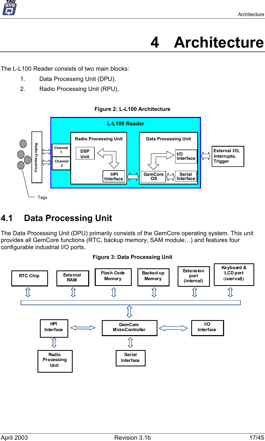
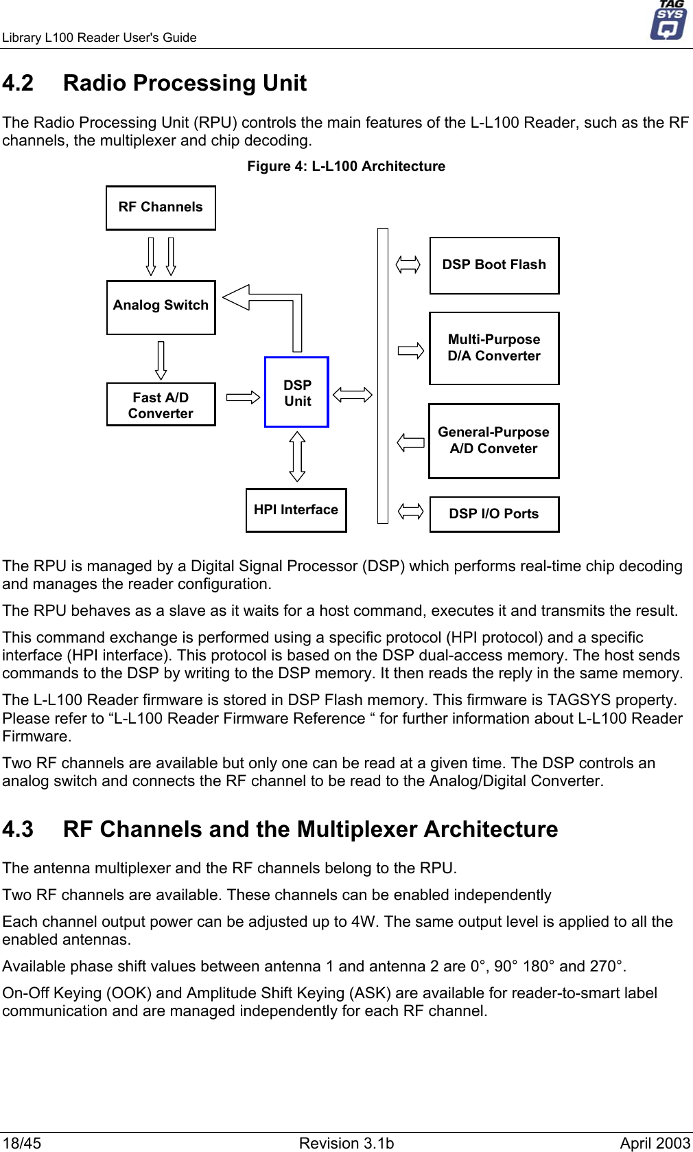
Users Manual LL100V31b

              Library L100 Reader User's Guide Revision 3.1b            TAGSYS April 2003
Library L100 Reader User's Guide     Publishing Information Disclaimer and Limitation of Liability All information herein is either public information or is the property of and owned solely by TAGSYS who shall have and keep the sole right to file patent applications or any other kind of intellectual property protection in connection with such information. Nothing herein shall be construed as implying or granting to you any rights, by license, grant or otherwise, under any intellectual and/or industrial property rights of or concerning any of TAGSYS’ information. This document can be used for informational, non-commercial, internal and personal use only provided that:    the copyright notice below, the confidentiality and proprietary legend and this full warning notice appear in all copies.   this document shall not be posted on any network computer or broadcast in any media and no modification of any part of this document shall be made. Use for any other purpose is expressly prohibited and may result in severe civil and criminal liabilities. The information contained in this document is provided “AS IS” without any warranty of any kind. Unless otherwise expressly agreed in writing, TAGSYS makes no warranty as to the value or accuracy of information contained herein. The document could include technical inaccuracies or typographical errors. Changes are periodically added to the information herein. Furthermore, TAGSYS reserves the right to make any change or improvement in the specifications data, information, and the like described herein, at any time. Therefore TAGSYS assumes no liability and is not responsible for customer applications or product or software that include TAGSYS products. TAGSYS HEREBY DISCLAIMS ALL WARRANTIES AND CONDITIONS WITH REGARD TO THE INFORMATION CONTAINED HEREIN, INCLUDING ALL IMPLIED WARRANTIES OF MERCHANTABILITY, FITNESS FOR A PARTICULAR PURPOSE, TITLE AND NON-INFRINGEMENT. IN NO EVENT SHALL TAGSYS BE LIABLE, WHETHER IN CONTRACT, TORT OR OTHERWISE, FOR ANY INDIRECT, SPECIAL OR CONSEQUENTIAL DAMAGES OR ANY DAMAGES WHATSOEVER INCLUDING BUT NOT LIMITED TO DAMAGES RESULTING FROM LOSS OF USE, DATA, PROFITS, REVENUES, OR CUSTOMERS, ARISING OUT OF OR IN CONNECTION WITH THE USE OR PERFORMANCE OF INFORMATION CONTAINED IN THIS DOCUMENT. TAGSYS does not and shall not warrant that this product/system/equipment will be resistant to all possible attacks, and shall not incur, and disclaims, any liability in this respect. Even if each product is compliant with current security standards in force on the date of their design, security mechanisms' resistance necessarily evolves according to the state-of-the-art in security and notably under the emergence of new attacks. Under no circumstances shall TAGSYS be held liable for any third party actions, and in particular in case of any successful attack against systems or equipment incorporating TAGSYS products. TAGSYS disclaims any liability with respect to security for direct, indirect, incidental or consequential damages that result from any use of its products. It is further stressed that independent testing and verification by the person using the product is particularly encouraged, especially in any application in which defective, incorrect, or insecure functioning could result in damage to persons or property, denial of service, or loss of privacy.  © Copyright TAGSYS 2000-2003 MS-DOS© and Windows© are registered trademarks of Microsoft Corporation.  Printed in France. TAGSYS – 180 Chemin de St Lambert, 13821 LA PENNE SUR HUVEAUNE, France. Tel: +33 (0) 4.91.27.57.00 / Fax: +33 (0) 4.91.27.57.01 Document Reference: 10242A0  2/45  Revision 3.1b  April 2003
    Read This First Read This First Welcome to the TAGSYS RFID System. This User's Guide is designed to help you get up and running quickly using this high-quality Radio Frequency Identification (RFID) system. It describes all you need to know about how to install and use the TAGSYS system and its associated applications. This document describes how to:  •  install the Library L100 Reader,  •  select the best-adapted configuration for your application, •  troubleshoot any eventual problems. This guide is designed for all TAGSYS partners and for TAGSYS Expert Network customers implementing a low-cost and high-performance RFID solution. This document does not require any previous knowledge of Radio Frequency Identification (RFID) technology.  Conventions Symbol Meaning  CAUTION: A note that advises users that a specific action could result in the loss of data or damage the hardware. WARNING: A note that advises users that a specific action may result in physical harm.   A note that provides additional information that helps the user perform a task or obtain the best performance from the product. Abbreviations and Acronyms AFI Application Family Identifier AON  All Or None API Application Programming Interface ASK  Amplitude Shift Keying CPU  Central Processing Unit CRC  Cyclic Redundancy Check DLL Dynamic-Link Library DPU  Digital Processing Unit DSFID  Data Storage Format Identifier DSP  Digital Signal Processor EAS  Electronic Article Surveillance ETX  End of Text April 2003  Revision 3.1b  3/45
Library L100 Reader User's Guide     HPI  Host Port Interface I/O Input/Output IFD Interface Device ILS  Integrated Library System LED  Light Emitting Diode LSb   Least Significant Bit LSB   Least Significant Byte MSb   Most Significant Bit MSB   Most Significant Byte OS Operating System PC Personal Computer PCB  Printed Circuit Board RAM  Random Access Memory RF Radio Frequency RFID  Radio Frequency IDentification RFU  Reserved for Future Use RPU  Radio Processing Unit RTC  Real Time Clock SAM  Security Access Module STX  Start of Text TTF  Tag Talks First TTL Transistor-Transistor Logic TTY TeleTYpe UID Unique Identifier  Glossary  Anti-Collision Tag capability making it readable while other tags are present in the RF field. Antenna An aerial that receives and/or transmits radio frequency signals. Aerials are manufactured in a variety of forms, shapes and sizes. Baud A unit of measure of data transmission speed representing the number of signal changes per second.  BNC Connector Cylindrical metal connector with a copper core that is located at the tip of a coaxial cable, and is used to connect cables together. It attaches by pushing and twisting the outer cylinder on to two locking pins. Reader See Reader.  Data Storage Format Identifier Identifies the structure of the data stored in the smart label. 4/45  Revision 3.1b  April 2003
    Read This First Digital Signal Processor This part of the Radio Processing Unit (RPU) performs real-time smart label decoding and manages the Medio L200 configuration. Dynamic-Link Library Executable routines that are stored as separate files with DLL extensions and executed only when needed by the program. Host Port Interface Interface used to access the DSP memory. IEC Connector Three-pin connector used on sockets that carry mains electricity to the computer. All PCs use a male IEC connector and mains lead with a female IEC connector. Interrogation Pulse A signal transmitted by the reader to activate the smart label’s transponder. Monitoring Port Parallel Port granting access to the HPI. It communicates directly with the Radio Processing Unit Multi-Read See Anti-Collision Nibble Half a byte (4 bits) Packaged Reader A reader in its casing. Phase Shift Difference of phase between the 13.56 MHz field emitted by two antennas. This feature is dedicated to rotating field applications and three-dimensional volume smart label detection. Protocol A set of rules governing a particular function, such as the flow of data/information in a communication system (communication between a smart label and a reader or a reader and a PC or host computer). Quiet Protection Mask Reserved for the C270 (I-Code™). This mask records the timeslots that may contain a selected chip in quiet mode. Radio Frequency Identification System (RFID) An automatic identification and data capture system comprising one or more readers and one or more smart labels in which data transfer is achieved by means of suitable modulated inductive or radiating electromagnetic carriers. Radio Processing Unit This unit controls the main features of the Medio L200, such as the RF channels, the multiplexer and the smart label decoding. Reader Electronic system for the communication between smart labels and host computers. Reader Talks First Chip protocol for exchanges between the reader and the chip, whereby the chip waits for a command from the reader to which it responds. RS-232 Electronic Industries Association (EIA) standard for serial interfaces between computers and peripherals which defines the function, the electrical characteristics and the timing of signals. RS-485 Electronic Industries Association (EIA) standard for multipoint, differential data transmission. It allows multiple nodes to communicate bi-directionally over 1 or 2 twisted pairs. Smart Label Small, flexible tag from the 13.56 MHz TAGSYS product line. A smart label is made of a chip connected to an etched antenna. Tag See Smart Label. Tag Talks First Chip protocol for exchanges between the reader and the chip, whereby the tag sends information continuously, without waiting for a specific command from the reader. Transceiver A combined transmitter and receiver. Transponder A combined receiver/transmitter that automatically transmits a signal when a ‘trigger’ is received by it. The trigger is often a pulse, called an interrogation pulse. April 2003  Revision 3.1b  5/45
Library L100 Reader User's Guide     If you need assistance Please contact your nearest TAGSYS sales representative or the TAGSYS welcome desk at: Telephone:  +33 (0) 4 91 27 57 00  Fax:  +33 (0) 4 91 27 57 01 E-Mail:  info@tagsys.net Contact for Comments We welcome your feedback to help us provide high quality documentation.  For technical comments, please contact our welcome desk: Telephone:  +33 (0) 4 91 27 57 00  Fax:  +33 (0) 4 91 27 57 01 E-Mail:  info@tagsys.net Please remember to quote the Document Reference Number 10242A0, your job title and your company. Quality Issues TAGSYS implements stringent quality controls at all stages of its manufacturing process. However, should you find a defect with this product, please notify your customer service representative using the dedicated Product Return Form. Telephone:  +33 (0) 4 91 27 57 36 Fax:  +33 (0) 4 91 27 57 02   6/45  Revision 3.1b  April 2003
    Read This First Table of Contents Publishing Information  2 Disclaimer and Limitation of Liability  2 Read This First  3 Conventions  3 Abbreviations and Acronyms  3 Glossary  4 If you need assistance  6 Contact for Comments  6 Quality Issues  6 1 For Your Safety  9 1.1 General Use  9 1.2 Care and Maintenance  9 1.3 Important Safety Information  9 1.3.1 Operating Environment  9 1.3.2 Electronic Devices  10 2 Certification  11 2.1 Occupational Health and Safety Notices  11 2.2 Regulatory Notices  11 2.2.1 In Europe (CE and RTTE Directives)  11 2.2.2 In USA (FCC Directive)  12 2.2.3 In Canada  13 3 Overview  14 3.1 Key Features  14 3.2 General Description  14 3.2.1 RF Channels  15 3.2.2 Synchronization Input/Output  15 3.2.3 I/O Port Connector  15 3.2.4 Init Button  15 3.2.5 Serial Connector  16 3.2.6 Monitoring Port (Parallel Port)  16 3.2.7 Antennas  16 4 Architecture  17 4.1 Data Processing Unit  17 4.2 Radio Processing Unit  18 4.3 RF Channels and the Multiplexer Architecture  18 5 Embedded Application  20 6 Antennas  21 7 Installation  23 7.1 General Installation  23 7.2 Mechanical Aspects  23 7.3 Cabling Requirements  23 7.4 Operating Modes  24 7.4.1 Test/Setup Mode  24 7.4.2 Main Operating Mode  25 8 Multiplexing Configuration  27 8.1 Windows™ DLLs  27 8.2 STX-E Protocol  27 April 2003  Revision 3.1b  7/45
Library L100 Reader User's Guide     8.3 Scanning (Reading)  27 8.4 3-D Rotating Field Applications  28 8.5 Pattern Examples  28 8.5.1 Enabling one Antenna after Another  28 8.5.2 Enabling both Antennas Simultaneously  29 8.5.3 Enabling each Antenna separately and then both at once  29 9 I/O Ports  30 9.1 General Purpose I/Os  30 9.2 Internal Connections  30 9.2.1 Input Configuration  30 9.2.2 Output Configuration  31 9.2.3 VOUT Characteristics  31 9.3 Input Configurations  31 9.4 Output Configurations  32 10 Calibration  34 11 Debugging  35 11.1 Debugging Tools  35 12 Technical Specifications  36 12.1 Technical Specifications  36 12.2 36 12.3 Serial Port Pin Assignment  37 13 Electrical Characteristics  38 13.1 Absolute Maximum Ratings  38 13.2 Standards Compliance  38 13.3 Power Supply DC Characteristics  39 13.4 Communication Link DC Characteristics and Timing  40 13.5 Antenna Electrical and Timing Characteristics  41 13.6 I/O Electrical and Timing Characteristics  42 14 Warranty Conditions  43 14.1 Warranty  43 14.2 Warranty Exclusions  43 14.2.1 General Provisions  44 14.2.2 How to Return Defective Products  44  8/45  Revision 3.1b  April 2003
    For Your Safety 1 For Your Safety 1.1 General Use The Library L100 Reader is designed to be rugged and reliable and to provide years of trouble-free service. Please observe the following general tips:   Take care not to scratch the device. Keep the device clean. When working with the device, use only TAGSYS-approved accessories.    This device is not waterproof and should not be exposed to rain or moisture. Under extreme conditions, water may enter the circuitry.    Take care not to drop the device or subject it to any strong impact.    Protect the device from extreme temperatures. For example, do not leave the device in front of a window on a hot day, and keep it away from heaters and other heat sources.   Do not store or use the device in any location that is extremely dusty, damp, or wet.    Use a soft, damp cloth to clean the device. If the surface of the device becomes soiled, clean it with a soft cloth moistened with a diluted window-cleaning solution. 1.2  Care and Maintenance This device is a product of superior design and should be handled with care. The suggestions below will further increase the lifetime of this device.    Keep the device and all parts and accessories out of the reach of small children.   Keep the device dry. Precipitation, humidity and liquids contain minerals that will corrode electronic circuits.   Do not use or store the device in dusty, dirty areas. Its moving parts can be damaged.   Do not store in hot areas. High temperatures can shorten the life of electronic devices, damage batteries and warp or melt certain plastics.   Do not store in cold areas. When the device warms up (to its normal temperature), moisture can form inside the device, which may damage electronic circuit boards.   Do not attempt to open the device. Non-professional handling of the device may damage it.   Handle the device with care. Shocks may break internal circuit boards.   Do not clean the device with harsh chemicals, cleaning solvents or strong detergents. Gently wipe the device with a soft cloth slightly dampened in a mild soap-and-water solution.   Do not paint the device. Paint may clog the device’s moving parts and prevent proper operation. Paint with metallic contents may limit device performance. 1.3  Important Safety Information 1.3.1 Operating Environment Follow all special regulations that are applicable in any area and always switch off the device whenever its use is prohibited, or when it may cause interference or danger. April 2003  Revision 3.1b  9/45
Library L100 Reader User's Guide     When connecting the device or any accessory to another device, read its user’s guide for detailed safety instructions. Do not connect incompatible products. As with all RF equipment, users are advised that the equipment should only be used in its normal operating position. 1.3.2 Electronic Devices Most modern electronic equipment is shielded from radio-frequency (RF) signals. However, other electronic equipment may not be shielded against the RF signals from your device. Medical Devices Operation of radio transmitting equipment, including RFID devices, may interfere with the functionality of inadequately protected medical devices. Consult a physician or the manufacturer of the medical device to determine if they are adequately shielded from external RF energy or if you have any questions. 10/45  Revision 3.1b  April 2003
  Certification 2 Certification 2.1  Occupational Health and Safety Notices TAGSYS Products have been designed not to exceed the limits given in the European Standard EN 50364 “Limitation of human exposure to electromagnetic fields from devices used in Electronic Article Surveillance (EAS), Radio Frequency Identification (RFID) and similar applications” in conjunction with the European Standard EN 50357 describing how to evaluate the exposure level. It is the responsibility of the TAGSYS Partner to install the Library L100 Reader as described in TAGSYS Documentation and with the appropriate antennas.  Modification of any TAGSYS Library System is prohibited without the written consent of TAGSYS. Unauthorized modifications may void the conformity of the equipment to safety standards and will void the TAGSYS warranty. An RF fields survey has been carried out on all the Library System components, in accordance with AS/NZS 2771.1: Radio Frequency Radiation, Part 1. According to this standard the maximum allowable RF exposure levels (non-occupational) at 3 kHz to 300 GHz are 200 µW/cm2.  2.2 Regulatory Notices An RFID system typically composed of an RF emission device such as the Library L100 Reader is subject to national regulations that may differ by country. One important item to consider is the maximum permissible magnetic field intensity at a distance of 10 meters from the antenna that must not exceed 42 dBµA/m in Europe and 38 dBµA/m in US. The Library L100 Reader meets these limits.   It is the responsibility of the TAGSYS Partner to install the Library L100 Reader as described in this User’s Guide or in TAGSYS Documentation. 2.2.1  In Europe (CE and RTTE Directives)  The Library L100 Reader complies (CE Declaration of Conformity granted) with the European EMC directive. The Library L100 Reader complies with the requirements of the Telecommunication Terminal Equipment Act (FTEG) and the RTTE Directive 1995/5/EC. It is the responsibility of the TAGSYS Reseller to install the Library L100 Reader as described in this Reference guide or TAGSYS Documentation. Any modification of the Library L100 Reader is prohibited without the written consent of TAGSYS. Unauthorized modifications may void the conformity of the equipment to CE and RTTE Directives and will void the TAGSYS warranty.   If a Library L100 Reader is further integrated in a different product, it is the responsibility of the manufacturer of this complementary product to obtain the required approvals for this product. April 2003  Revision 3.1b  11/45
Library L100 Reader User's Guide     2.2.2  In USA (FCC Directive) The Library L100 Reader has been designed to comply with Part 15 of the FCC Rules. Furthermore typical configurations based on a Medio S002 have been successfully tested with Part 15 of the FCC rules (FCC ID Numbers are listed on all system-mounted TAGSYS Antennas).   Library L100 Reader WARNING TO USERS IN THE UNITED STATES FEDERAL COMMUNCIATIONS COMMISSION (FCC) RADIO INTERFERENCE STATEMENT 47 CFR Section 15.105(b)  This equipment has been tested and found to comply with the limits for a Class B digital device, pursuant to Part 15 of the FCC Rules. These limits are designed to provide reasonable protection against harmful interference in a residential installation. This equipment generates, uses and can radiate radio frequency energy and if not installed and used in accordance with the instructions may cause harmful interference to radio communications. However, there is no guarantee that interference will not occur in a particular installation. If this equipment does cause harmful interference to radio or television reception, which can be determined by turning the equipment off and on, the user is encouraged to try to correct the interference by one or more of the following measures:  ▪   Reorient or relocate the receiving antenna. ▪   Increase the separation between the equipment and receiver. ▪   Connect the equipment into an outlet on a circuit different to that to which the receiver is connected. ▪   Consult the dealer or an experienced radio/TV technician for help.  NO UNAUTHORIZED MODIFICATIONS 47 CFR Section 15.21 CAUTION: This equipment may not be modified, altered, or changed in any way without signed written permission from TAGSYS SA. Unauthorized modification may void the equipment authorization from the FCC and will void the TAGSYS warranty.  ANTENNA REQUIREMENT 47 CFR Section 15.203 CAUTION: This equipment must be professionally installed. The installer shall be responsible for ensuring that the proper antenna is employed so that the limits in this part are not exceeded. Non-professional installation or installation of the equipment with an improper antenna may void the equipment authorization from the FCC and will void the TAGSYS warranty. Operation is subject to the following two conditions: (1) The system devices may not cause harmful interference, and (2) The library system devices must accept any interference received, including interference that may cause undesired operation. 12/45  Revision 3.1b  April 2003
  Certification 2.2.3 In Canada Cet appareil numérique de la classe B respecte toutes les exigences du Règlement sur le matériel brouilleur du Canada. This Class B digital apparatus meets all requirements of the Canadian Interference-Causing Equipment Regulations.  April 2003  Revision 3.1b  13/45
Library L100 Reader User's Guide     3 Overview The TAGSYS Library L100 (L-L100) smart label packaged reader is intended for Original Equipment Manufacturer (OEM) applications.  The L-L100 reader incorporates hardware, software and other components that manage the Radio Frequency (RF) interface as well as the external connections for power, data exchange and various communication protocols. The TAGSYS L-L100 reader is specifically designed for use in a library environment and therefore is easily integrated into Integrated Library System (ILS) applications. Customized software, such as STXE Protocol application or the Teletype (TTY) menu application, can be easily downloaded. 3.1 Key Features •  13.56 MHz RF multi-channel packaged reader •  Multiple tag compatibility (TAGSYS and ISO15693 smart labels) •  Standard software applications  •  High RF output power, with software configuration •  Software-configurable multiplex operating mode •  Two dedicated processing units, namely a microcontroller for the customer application and a Digital Signal Processor (DSP) unit for real-time signal processing •  Serial communication with an embedded end-user application •  Multi-purpose configurable industrial I/O ports •  Parallel port monitoring 3.2 General Description Figure 1: L-L100 Packaged Reader  14/45  Revision 3.1b  April 2003
  Overview 3.2.1 RF Channels The L-L100 Reader can drive up to two antennas with each channel able to drive up to four watts. LEDs indicate which RF field (channel) is transmitting (green).   CAUTION: The antenna MUST be connected to the reader before the unit is turned on. 3.2.2  Synchronization Input/Output  When configured for input, this BNC connector makes it possible to use an external 27.12-MHz clock to generate the RF field, instead of the internal clock generator. When configured as output, this connector can drive other L-L100 readers and provide the 27.12-MHz clock. The Sync LED indicates the clock mode: •  Red: The internal clock generator is enabled and an external clock signal cannot be input. •  Green: The internal clock generator is disabled. A 27.12-MHz clock signal must be connected to the Sync In/Out connector. By default, the internal clock mode is applied and the Sync In/Out connector is configured as an output. If the external clock mode is required, contact your TAGSYS sales representative. 3.2.3  I/O Port Connector The L-L100 reader provides four Input/Output (I/O) ports. Each I/O can be independently configured as an input or output by the application software.  When configured as outputs, I/Os are open drain (250 mA). A pull-up supply must be connected to the I/O port reference input (VIN). The pull-up supply voltage range is between 5V and 28V. When configured as inputs, the I/O input signal range is between 0V and 28V. I/O port LEDs indicate whether the I/O is configured for input (green) or output (red). Please refer to Section 9, "I/O Ports" for more information.   Industrial I/O ports can only be accessed via the Data Processing Unit (DPU). 3.2.4 Init Button The Init button aborts the embedded application stored in the Data Processing Unit memory. The L-L100 Reader is then ready to be downloaded with a new application.    The L-L100 Reader must be switched off and then back on before an embedded application takes effect. April 2003  Revision 3.1b  15/45
Library L100 Reader User's Guide     3.2.5 Serial Connector The serial connector is used to communicate with an external environment. User commands and data exchanges are transmitted through this port which can be set to RS-232, RS-485 or RS-422 mode by the software. Different baud rates can be defined for each mode. The Default Mode is defined by the application software which is downloaded in the L-L100 Reader. Tx (Transmit data) and Rx (Receive Data) LEDs indicate the activity of the serial port.   The RS-232 cable is a null modem cable. Please refer to Embedded Application chapter for further information about Application Software. 3.2.6  Monitoring Port (Parallel Port) The monitoring port communicates directly with the Radio Processing Unit (RPU). When the parallel cable is plugged in, the Data Processing Unit (DPU) is automatically deselected. The parallel port can be used as a monitoring tool or as a means to upgrade the L-L100 Reader firmware via the L200 Explorer.   The parallel cable uses pin-to-pin DB25 connectors. A shielded cable must be used to prevent disruptions when antennas have a high output power.   Please refer to L-L100 Reader Architecture chapter for further information about the RPU and DPU. Please refer to “L-L100 Reader Firmware Reference” for further information about L-L100 Reader Firmware. 3.2.7 Antennas The L-L100 Reader is primarily designed for use with Aero-LI, L-SA1 and L-SA2 antennas. Nonetheless, it is also operational with other TAGSYS antennas, provided that the power applied to the antenna does not exceed antenna specifications. For more information, refer to Section 6, "Antennas".   L-L100 Reader performance has been characterized for a 3-meter long antenna cable. Optimized operation is not guaranteed with a cable longer than three meters.  16/45  Revision 3.1b  April 2003
  Architecture 4 Architecture The L-L100 Reader consists of two main blocks:  1.  Data Processing Unit (DPU). 2.  Radio Processing Unit (RPU),  Figure 2: L-L100 Architecture Data Processing UnitSerialInterfaceHPIInterfaceDSPUnitChannel1Channel2GemCoreOSRadio Processing UnitL-L100 ReaderRadio FrequencyI/OInterfaceExternal I/O,Interrupts,TriggerTags 4.1  Data Processing Unit The Data Processing Unit (DPU) primarily consists of the GemCore operating system. This unit provides all GemCore functions (RTC, backup memory, SAM module…) and features four configurable industrial I/O ports. Figure 3: Data Processing Unit GemCoreMicroControllerRTC ChipI/OInterfaceExt e ns io nport(internal)SerialInterfaceExt e rn a lRAMHPIInterfaceFlas h CodeMemoryBacked upMemoryRadioProcessingUnitKe yboard &LCD port(internal))  April 2003  Revision 3.1b  17/45
Library L100 Reader User's Guide     4.2  Radio Processing Unit The Radio Processing Unit (RPU) controls the main features of the L-L100 Reader, such as the RF channels, the multiplexer and chip decoding. Figure 4: L-L100 Architecture DSPUnitDSP Boot FlashMulti-PurposeD/A ConverterGeneral-PurposeA/D ConveterFast A/DConverterAnalog SwitchDSP I/O PortsRF ChannelsHPI Interface The RPU is managed by a Digital Signal Processor (DSP) which performs real-time chip decoding and manages the reader configuration. The RPU behaves as a slave as it waits for a host command, executes it and transmits the result.  This command exchange is performed using a specific protocol (HPI protocol) and a specific interface (HPI interface). This protocol is based on the DSP dual-access memory. The host sends commands to the DSP by writing to the DSP memory. It then reads the reply in the same memory.  The L-L100 Reader firmware is stored in DSP Flash memory. This firmware is TAGSYS property. Please refer to “L-L100 Reader Firmware Reference “ for further information about L-L100 Reader Firmware. Two RF channels are available but only one can be read at a given time. The DSP controls an analog switch and connects the RF channel to be read to the Analog/Digital Converter. 4.3  RF Channels and the Multiplexer Architecture The antenna multiplexer and the RF channels belong to the RPU.  Two RF channels are available. These channels can be enabled independently Each channel output power can be adjusted up to 4W. The same output level is applied to all the enabled antennas. Available phase shift values between antenna 1 and antenna 2 are 0°, 90° 180° and 270°. On-Off Keying (OOK) and Amplitude Shift Keying (ASK) are available for reader-to-smart label communication and are managed independently for each RF channel. 18/45  Revision 3.1b  April 2003
  Architecture Figure 5: L-L100 Antenna Multiplex Antenna 1Antenna 2∆ϕ = 0°, 90°, 180°or 270°Enable Antenna 1Enable Antenna 2   April 2003  Revision 3.1b  19/45
Library L100 Reader User's Guide     5 Embedded Application The embedded software application is based on the GemCore operating system which is stored in the Flash memory of the Data Processing Unit.  Different applications can be downloaded into the L-L100 Reader, but only one can be stored at a single time. Depending on the software application downloaded into the GemCore Flash memory, it may be possible to access all or part of the L-L100 Reader functions. The STXE standard protocol application is delivered with the L-L100 Reader:   STXE Protocol is the TAGSYS standard protocol. It is compatible with most of TAGSYS range reader products. We advise to use STXE protocol in order to address all TAGSYS reader functions.  20/45  Revision 3.1b  April 2003
  Antennas 6 Antennas TAGSYS L-L100 readers are optimized for use with TAGSYS antennas.  The antennas are factory-calibrated to an impedance of 50 Ohms which offers optimal performances when the antenna is mounted on a desktop surface. Due to their specific design, these antennas can be safely used in proximity to other TAGSYS RFID products. They will also work, if properly installed, in metallic-type environments. In this case, performance may be reduced. TAGSYS antennas are provided with rubber feet to operate in a standard desktop configuration. However, a mounting kit is also supplied for installation underneath a table or desk. Antennas are delivered with a standard plastic cover. This cover can be replaced by another made of a non-metallic and non-conductive material. This cover should be as thin as possible as not to impact the performance of the stack programming function. In addition, we strongly recommend placing the antenna directly on the desk. It may be necessary to retune the antenna once installed if the environment is highly metallic or if the antenna is installed underneath a table or desk (and depending on the material of which the desk/table is manufactured).  When installing a dual-antenna arrangement, a proximity effect may be created when using Aero LI antennas. L-SA1 and L-SA2 are specifically designed to reduce this effect. Table 1: Antenna Characteristics Parameter L-PS1  Aero LI  L-SA2  L-SA1 Dimensions  255 x 216 x 20 mm. 10 x 8½ x ¾ in. 288 x 263 x 17 mm. 11⅓ x 10⅓ x ⅔ in. 440 x 370 x 18 mm. 17⅓ x 14½ x ⅔ in. 650 x 440 x 18 mm. 25 ⅔ x 17⅓ x ⅔ in Single Ferrite Yes Yes Yes Yes Characteristics Single-loop  Single-loop  Single-loop  Double-loop Housing  Plastic ABS UL 94-V0 Weight  2.0 kg.  2.0 kg.  2.5 kg.  5 kg. Operating Temperature  0 °C to +55 °C Storage Temperature  -25 °C to +60 °C Maximum  Output Power 1 0.25 W  8 W  3 W Operating Frequency  13.56 MHz Impedance  50±5 Ω and 0 ± 5° Antenna Connection  Not applicable  BNC 50 Ω Antenna Connection cable  Not applicable  RG-58, 50 Ω 1 FCC-compliant antennas are available (maximum output power of 1 W). April 2003  Revision 3.1b  21/45
Library L100 Reader User's Guide     Table 2: Minimum Single-Antenna Station Performance   Single-Antenna Stations  Dual-Antenna Stations Parameter  L-PS1  Aero LI  L-SA2  Aero LI1 L-SA1 Reading  3 ½ in. (89 mm.)   6 in. (152 mm.)  7 in. (178 mm.)  6 in. (152 mm.)  6 ½ in. (165 mm.) Writing  3 in. (76 mm.)  4½ in. (114 mm.)  5 ½ in. (140 mm.)  4 in. (102 mm.)  4½ in. (114 mm.) Minimum reading/writing distance for stacks: 4 in. (102 mm.) 1 Multiplexed with L-L100 reader.  Performance given for single tag operation and measured on any point above the RF loop. In the middle of the loop, the performance may be greater. This does not include the L-PS1 where performance has been measured with tag centered on the station.  22/45  Revision 3.1b  April 2003
  Installation 7 Installation 7.1 General Installation Read/antenna/ILS layout and maximum cable distances, to be specified. 7.2 Mechanical Aspects The L-L100 Reader is delivered with four rubber pads screwed on the bottom of the package for installation on a table or desk. A mounting plate available with the L-L100 Reader can be used to mount the unit in various positions. When mounted vertically, the BNC connectors must be facing upwards and perpendicular to the floor.  When installing the L-L100 Reader on the mounting plate, remove the rubber pads from the L-L100 Reader and fasten the unit directly to the mounting plate.    CAUTION: The screws must be always attached to the bottom of the L-L100 Reader even if the rubber pads and mounting plate are not used.  Figure 6: Authorized Installation Positions BNC Connectors on Top   CAUTION: For continuous protection against risk of fire, use only T 2.5A – 250V rated fuses. 7.3 Cabling Requirements All L-L100 Reader cables must be shielded. Shielding effectiveness of the material used should be of Good performance (60dB min.), especially in the frequency range of 10 to 60 MHz. The addition of ferrite clamps near the input/output will increase common mode rejection. TAGSYS antenna products are delivered with good performance shielded coaxial cables with ferrite beads already mounted to increase shielding effectiveness at low frequencies. April 2003  Revision 3.1b  23/45
Library L100 Reader User's Guide     7.4 Operating Modes The L-L100 Reader can be setup in one of two operating modes: •  Test/Setup mode used to test and develop your application, •  Main Operating mode for running your application.   CAUTION: The antenna MUST be connected to the reader unit before the reader is turned on. 7.4.1 Test/Setup Mode The RPU host is connected to the L-L100 Reader by a parallel interface linking it to the monitoring host, which is a computer. The L200 Explorer software is designed to set-up the L-L100 Reader and to execute chip commands in a Windows environment.  This operating mode is useful to learn all L-L100 Reader basic functions and to rapidly start using the packaged reader in a specific RFID application. The L200 Explorer software is also a powerful and easy-to-use tool to define the best RFID set-up for a custom application.   For additional information about the L200 Explorer software, refer to the L200 Explorer User’s Guide. Figure 7: Test/Setup Mode Data Processing UnitSerialInterfaceHPIInterfaceDSPUnitChannel 1Channel 2GemCoreOSRadio Processing UnitL-L100 ReaderRadio FrequencyI/OInterface External I/OsTagsL200 Explorer(Parallel Port)   CAUTION: The antenna MUST be connected to the reader unit before the reader is turned on. In this mode, the L-L100 Reader is directly connected to the host PC via the DB25 parallel port connector. Reader commands are only accessed using the L200 Explorer software. 1.  Connect the antennas to the required inputs, according to application specifications. 2.  Connect the L-L100 Reader monitoring port to the PC using the shielded parallel cable. 24/45  Revision 3.1b  April 2003
  Installation 3.  Connect the L-L100 Reader to the AC supply. 4.  Start the L200 Explorer software application. You can now configure the RPU of your L-L100 Reader as desired and start using most L-L100 Reader functions.   Test/Setup Mode is only available when using L200 Explorer Software. In this mode, certain Data Processing Unit functions cannot be accessed. 7.4.2 Main Operating Mode In Main Operating mode, the Data Processing Unit (DPU) is the RPU Host. The DPU can access the DSP memory via the HPI interface.  When the L-L100 Reader Main Operating Mode is used, the DPU is the interface between the RPU and the environment. In that case, the DPU can exchange data with a host system through the embedded serial port interface.    When the Main operating mode is used, the host system is not connected to the RPU. In other words, when the host system requires a command which must be executed by the RPU, the GemCore OS receives this request and sends the corresponding command to the RPU. The Main Operating mode is also designed for using the L-L100 Reader as a standalone device, without a host. Once the RFID system has been completely defined and it is ready for an industrial application, the L-L100 Reader can be interfaced to specific network systems and various communication protocols. This interface is implemented using custom DPU Application Software.   The command set and communication protocol between the DPU and the RPU are completely defined by the DSP Firmware. It therefore cannot be customized.  On the other hand, the command set and the communication protocol between the DPU and the L-L100 Reader Host are defined by the DPU application software. Developing new DPU application software makes it possible to interface the L-L100 Reader with new environments and to communicate using new protocols. Figure 8: Main Operating Mode Data Processing UnitSerialInterfaceHPIInterfaceDSPUnitChannel 1Channel 2GemCoreOSRadio Processing UnitL-L100 ReaderRadio FrequencyI/OInterface External I/OsTagsSTX-E Protocol(Serial Port)  April 2003  Revision 3.1b  25/45
Library L100 Reader User's Guide      CAUTION: The antenna MUST be connected to the reader unit before the reader is turned on. When your application is fully developed and ready for use, configure the Main Operating mode: 1.  Connect the antennas to the required inputs, according to application specifications. 2.  Connect the L-L100 Reader serial port to the PC or to the terminal using a serial cable. 3.  Connect the pull-up supply and I/O ports if required. 4.  Make sure that the monitoring port is not connected to the parallel cable. 5.  Connect the L-L100 Reader to the AC supply. The Application software stored in Data Processing Unit is now running and the application is ready for use. 26/45  Revision 3.1b  April 2003
  Multiplexing Configuration 8 Multiplexing Configuration The L-L100 Reader is designed with two transmit channels but with only one receive channel. This means that each antenna can transmit an RF field used to read tags, but tag contents can only be read by one antenna at a single time.  Tag reading performance can be enhanced by using the L-L100 Reader to perform read operations on both antennas one after the other.  In addition, a phase shift can be applied between Antenna 1 and Antenna 2 for 3-D rotating field applications. These parameters are selected in Multiplexing mode which allows the user to completely define a system based on its multiplexing configuration.  In particular, the following parameters are defined by the multiplexing mode: •  the transmitting antennas, •  the phase shift between the antennas, •  which antenna is read, and for how long.  8.1 Windows™ DLLs The Library Windows™ DLLs automatically manage multiple-antenna applications for the L-L100 Reader.  The DLLs take advantage of multi-channel readers (L-L100 Library) for both reading and writing using several specific functions. For more information, refer to the Library Windows™ DLL Programming Guide. 8.2 STX-E Protocol The STX-E Protocol can be used to develop dedicated application programs. For more information, refer to the MedioSTX DLL Programming Guide.  Multiplexing information is organized into patterns. A sequence contains between one and eight patterns that are applied one after the other in a loop. The L-L100 Reader can only store a single sequence. Figure 9: Sequence of Patterns in a Loop Pattern 1 Pattern 2 Pattern 3 ...Pattern nIf n patterns are defined The multiplexing mode enables the user to implement several combinations on the basis of this physical configuration. The following paragraphs provide implementation examples and show how to choose the pattern. 8.3 Scanning (Reading) The scanning parameters define which antenna is read (receives tag information), when it is read and for how long.  April 2003  Revision 3.1b  27/45
Library L100 Reader User's Guide     For each pattern, the transmitting antennas will be read a set number of times. The number of scans defines the global number of antenna read operations to be performed on each pattern. The order in which antennas are read is always: Antenna 1 (if selected) and then Antenna 2 (if selected). The number of scans is common to all patterns, regardless of the number of antennas selected in the pattern. Each pattern is executed for the same length of time regardless of the number of antennas selected in the pattern.  The duration of each scan period is defined as follows:  •  For Reader Talks First (RTF) smart labels, the scanning duration gives the number of Read commands sent to the tags during a single scan period. (Minimum Recommended Scan Duration is 20 Read commands)   For RTF tags, L-L100 Reader must send a Read command to tag for it to be read.  •  For Tag Talks First (TTF) smart labels, the scanning duration gives the time during which the reading process is activated on one antenna during a single scan period. (Minimum Recommended Scan Duration is 100 ms.)   When a TTF tag is detected, the read operation will be completed even if the scan duration period has expired. In other words, the actual scan duration may be longer when a TTF tag is processed at the end of the scan period.  For more information about Scan Number and Scan Duration parameters, refer to the example given in Section 8.5.3, "Enabling each Antenna separately and then both at once". 8.4  3-D Rotating Field Applications Phase shifts can be used to detect tags in a 3-D rotating field application. Phase shifts of 0°, 90°, 180° or 270° are available.  In this case, both antennas must be enabled (transmitting) simultaneously in order for the two phases to create a 3-dimensional RF field.  8.5 Pattern Examples 8.5.1  Enabling one Antenna after Another This is the most common example of a tag-reading pattern and requires the use of two patterns. The first one enables only Antenna 1, while the second enables only Antenna 2. In Pattern 1, Antenna 1 is enabled and then the detected tags are read. Afterwards in Pattern 2, Antenna 1 is disabled, Antenna 2 is enabled and then the detected tags are read.   Channel 1 2 Pattern 1  Enabled  Disabled Pattern 2  Disabled  Enabled 28/45  Revision 3.1b  April 2003
  Multiplexing Configuration   The advantage of this configuration is that the two antennas are not enabled at the same time, reducing interference. 8.5.2  Enabling both Antennas Simultaneously This configuration is implemented with only one pattern which enables Antennas 1 and 2 at the same time. This configuration is best used for detecting smart labels in 3-dimensional rotating field applications. For more information, refer to Section 8.4, "3-D Rotating Field Applications". In this case, a phase shift should be applied to one of the antennas in order to create a 3-D RF field. Both Antennas 1 and 2 are enabled and the tags detected by Antenna 1 are read and then the tags detected by Antenna 2 are read. (Only one channel can be read at a single time.)  Channel 1 2 Pattern 1  Enabled  -Enabled 8.5.3  Enabling each Antenna separately and then both at once Depending on the application requirements, in this configuration each antenna can be enabled separately and then both at once.  In order to implement this configuration, three patterns are necessary. The first one enables only Antenna 1, the second enables only Antenna 2 and the third enables both Antennas 1 and 2.  Channel 1 2 Pattern 1  Enabled  Disabled Pattern 2  Disabled  Enabled Pattern 3  Enabled  -Enabled In this example, the scanning parameters must be carefully selected. As both the Scan Number and Scan Duration parameters are the same for all three patterns, if the Scan Number is set to 1, Antenna 2 in Pattern 3 will not be read. If the Scan Duration is set to 100 ms. and the Scan Number is set to 2, the tags detected by Antenna 1 will be read twice (for 100 ms each time) in Pattern 1, then the tags detected by Antenna 2 will be read twice (for 100 ms each time) in Pattern 2. In Pattern 3, the tags detected by Antenna 1 will be read once for 100 ms. and then the tags detected by Antenna 2 will be read once for 100 ms. In the event that the Scan Number parameter is set to 3, the tags detected by Antennas 1 and 2 are read three times in Patterns 1 and 2, respectively. In Pattern 3, the tags detected by Antenna 1 are read once, then the tags detected by Antenna 2 are read once, and then the tags detected by Antenna 1 are read a second time.    Each pattern will be executed for the same amount of time regardless of the number of antennas selected in the pattern.  This duration is equal to the Scan Number x Scan Duration. April 2003  Revision 3.1b  29/45
Library L100 Reader User's Guide     9 I/O Ports The L-L100 Reader features four I/O ports. All four I/O ports can be configured independently as a general purpose input or output.  Depending on the Application software downloaded in the DPU, the I/O port may command a relay, trigger specific commands (Windowing…) or read input signals.   The I/O Port is controlled by the DPU with commands using STX protocol. This means that I/Os are not controlled by the RPU which uses DLLs. 9.1  General Purpose I/Os Each I/O can be configured independently as an input or output. When an I/O is configured as input, it can be used to connect sensors or industrial logic commands to execute a specific task. For instance, the L-L100 Reader can execute a smart label Read command according to the logical level of the input command. When the I/O is configured as output, it can command a relay or any other transducer. •  Input:  Industrial logic (0V to 28V) TTL-compatible. •  Output:  Open drain, 250 mA (maximum). 9.2 Internal Connections This paragraph describes I/O electronic schematics when the configuration is set to input or output. It also gives the characteristics of the VOUT supply which is available on the I/O port. 9.2.1 Input Configuration Figure 10: I/O Configured as Input  30/45  Revision 3.1b  April 2003
  I/O Ports 9.2.2 Output Configuration Figure 11: I/O Configured as Output  9.2.3 VOUT Characteristics Figure 12: VOUT Characteristics  VOUT: •  Output DC 28V. •  Output current max: 100 mA 9.3 Input Configurations When an I/O port is configured as an input, the external logic signal must be connected directly to the input (0V-24V) of the requested I/O port. If the output of the external logic signal is an open-collector output, the VIN signal must be connected to a supply (VOUT or external supply) or to the ground to pull up/down the I/O port. In this case, all the grounds must be connected together (external logic, external supply and L-L100 Reader ground supply). The following examples show how to connect a signal (from a sensor, a push-button, etc…) to the L-L100 Reader. April 2003  Revision 3.1b  31/45
Library L100 Reader User's Guide     Figure 13: Connecting a “Totem-Pole” Sensor  Figure 14: Connecting an “Open-Collector” Sensor (N Type)  Figure 15: Connecting an “Open-Collector” Sensor (P Type)  9.4 Output Configurations When an I/O port is configured as an output, the VIN signal must be connected to a supply to pull up the I/O port when it is not activated. Setting the I/O port pulls down its output to the GND. VOUT supply may be used to supply VIN signal and the external load. The following examples show how to connect a load ( a relay, a light, etc.) to the L-L100 Reader using the internal supply (VOUT) or an external supply. 32/45  Revision 3.1b  April 2003
  I/O Ports Figure 16: Connecting a load using the internal supply (VOUT)  Using an external supply  Figure 17: Connecting a load using an external supply  When the I/O port is set, the relay is activated. When the I/O port is reset, the relay is not activated. April 2003  Revision 3.1b  33/45
Library L100 Reader User's Guide     10 Calibration The L-L100 Reader features an innovative technology based on Digital Signal Processing (DSP) to optimize long-distance reading and writing performances. In particular, the L-L100 Reader is very efficient even in industrial and noisy environments. Environmental conditions can vary significantly according to the application-specific factors such as antenna size, output power, machines close to the L-L100 Reader, etc. Such parameters can create noise around the RFID system. In order to optimize the performance of your RFID system, it is possible to calibrate the L-L100 Reader. The calibration consists of selecting the best trigger threshold used to capture and decode a smart label signal. The trigger threshold value corresponds to the sensitivity of the L-L100 Reader making it possible to differentiate a smart label signal from a noise signal. If the trigger threshold value is too low, the L-L100 Reader may start decoding a signal which actually is a noise signal. In this case, the decoding efficiency of the L-L100 Reader may decrease. If the trigger threshold value is too high, the L-L100 Reader will not decode a low-magnitude smart label signal (because it treats it as an ambient noise signal). In this case, reading distance performance may decrease. Ultimately, a compromise must be selected to find the best trigger threshold value. The L200 Explorer application defines the optimized trigger threshold value. Please refer to the L200 Explorer User’s Guide for further information. Default trigger threshold values stored in the L-L100 Reader upon delivery depend on the smart label type. These trigger values are optimized for Aero-LI, L-SA1 and L-SA2 antennas at middle-range power.   The calibration process is only available for C210, C220 and C240 tag types.   CAUTION: C210 and C240 decoding algorithms have been modified to improve L-L100 Reader performances. It is possible that trigger values optimized for L-L100 Reader Firmware releases previous to version 3.0 must be changed when using version 3.0 or more recent.  34/45  Revision 3.1b  April 2003
  Debugging 11 Debugging 11.1  Debugging Tools  The L-L100 Reader features debugging tools to optimize your RFID system installation and communication with the tags. Debugging tools can only be accessed with the L200 Explorer Software and consist of: •  A real-time oscilloscope to display the antenna signals received by the L-L100 Reader, •  A real-time frequency analyzer to display the frequency information of the Antennas signal, •  Some statistic information about the quality of your RFID System environment   Please refer to “Medio L200 Explorer User’s Guide” for further information about debugging tools.   April 2003  Revision 3.1b  35/45
Library L100 Reader User's Guide     12 Technical Specifications 12.1 Technical Specifications Table 3: Technical Specifications Parameter Value Size (L x W x H)  310 x 260 x 80 mm. (12.2 x 10.2 x 3.1 in.) Weight  4.5 kg. (10 lbs.) Power Supply  85 to 265 V AC / 50/60 Hz Chip compatibility  TAGSYS C220 (Firmware upgrade required for other chips) Communication Speed  Serial: Up to 38.4 Kbps  Parallel: Up to 200 Kbps Communication Interface  Serial: RS-232, RS-485 and RS-422 Parallel: Bi-directional and Enhanced RF Output Power  Up to 4 W with multiplex capability and balanced 0° / 90° / 180° operation Power Consumption   Up to 40 W Operating temperature  0°C / +55°C (+32°F / +131°F) Storage temperature  -20°C / +70°C (-4°F / 158°F) Mechanical Interface  Rubber pads (Desktop) or metal mounting plate (with screws for vertical installation) Conformity CE, UL EN 300-330, ETS 300-683 European Radio FCC Part 15 (for typical configurations) Reading/Writing Distance  Up to 120 cm (47¼  inches) in a gated antenna configuration Antenna Compatibility  50-Ohm antenna Application Software  512 KB of Flash memory Inputs/Outputs  4 I/O ports independently configurable 12.2  36/45  Revision 3.1b  April 2003
  Technical Specifications 12.3  Serial Port Pin Assignment Figure 18: RS-232 Serial Link Connector Diagram 123456 7 8 9  Connector  Description   Connector  Description  1  NC  6  TRx+ RS485/ Rx+ RS422 2  Rx RS232 / TRx- RS485 / Rx- RS422  7  NC 3  Tx RS232 / TRx- RS485 / Tx- RS422  8  NC 4  NC  9  TRx+ RS485/ Tx+ RS422 5 NC      April 2003  Revision 3.1b  37/45
Library L100 Reader User's Guide     13 Electrical Characteristics This chapter provides information about AC and DC electrical characteristics for all pins. It also gives timing characteristics for the different interfaces. 13.1  Absolute Maximum Ratings Parameter Value Ambient Operating Temperature   0°C to +55°C Storage Temperature  -20°C to +70°C Supply Voltage (VCC pin) with respect to GND  6 V Shutdown Voltage (SHDW pin)   6 V Total Power Dissipation   0.8 W Total Power Dissipation on Antenna (ANT pin)   0.2 W DC Current Allowed on VCC Pin   200 mA Peak Current Allowed on VCC Pin   400 mA Input Voltage on IOx, Signal Detection and TX_TTL pins   5 V Output Current Sunk by IOx, Signal Detection and TX_TTL pins   20 mA Output Current Sourced by IOx, Signal Detection and TX_TTL pins   20 mA Input Voltage Range on RX_RS232 pin   ±25 V ESD Protection on RX_RS232 and TX_RS232 pins  ±15 kV 13.2 Standards Compliance The L-L100 Reader is compliant with the following standards:   CE   ARIB T60 (Japanese Radio Standard Compliance)   ETSI 300-330 (European Radio Compliance) The L-L100 Reader is also compliant with FCC part 15 regulations. 38/45  Revision 3.1b  April 2003
  Electrical Characteristics 13.3  Power Supply DC Characteristics Parameters Conditions Min. Typ. Max. Unit Comments VCC Power Input Voltage    4    6  V   VCC Power On Input Peak Current    300  mA  VCC Power On Input Peak Current Recovery Time     10 ms  Input Voltage = 4V    185    mA  All peripherals powered RF On Input Voltage = 5V    140    mA   Input Voltage = 6V    115    mA   Input Voltage = 4V    25    mA  All peripherals powered RF Off Input Voltage = 5V    20    mA   Input Voltage = 6V    18    mA   Input Voltage = 4V      14  mA  Sleep Mode (firmware) Input Voltage = 5V      12  mA   Input Voltage = 6V      10  mA   Input Voltage = 4V    340    µA  Shutdown State (Pin) Input Voltage = 5V    420    µA   VCC Input Current (No I/Os connected*) Input Voltage = 6V    500    µA   (*) : The power requirements of a connected I/O increase the reader total consumption. Figure 19: Input Current vs. Temperature (VCC Pin at 5 V – RF On - No I/O Connected) 050100150-10 0 10 20 30 40 50 60Temperature (°C)Input Current (mA)  April 2003  Revision 3.1b  39/45
Library L100 Reader User's Guide     13.4  Communication Link DC Characteristics and Timing Parameters Conditions Min. Typ. Max. Unit Comments RX_TTL Input Voltage Low    0    1  V   RX_TTL Input Voltage High    4  5    V   RX_TTL Input Current      1    µA   TX_TTL Output Voltage Low        0.6  V   TX_TTL Output Voltage High    4.3      V   TX_TTL Output Current        20  µA  Sunk or sourced TX_TTL Output Capacitance        50  pF   RX_RS232 Input Voltage Range    -25    +25  V   RX_RS232 Input Threshold Low  25°C  0.8  1.5    V   RX_RS232 Input Threshold High  25°C    1.8  2.4  V   RX_RS232 Input Hysteresis      1.8  2.4  V   RX_RS232 Input Resistance    3  5  7  kΩ  TX_RS232 Output Voltage Swing  Loaded with 3 kW to GND  ±5 ±5.4    V  TX_RS232 Output Resistance    300  1000    kΩ  TX_RS232 Short-circuit Current        ±60  mA   IEC 1000-4-2 Air-Gap Discharge   ±15  kV  IEC 1000-4-2 Contact Discharge   ±8  kV  ESD Protection on both pins Human body model    ±15    kV   4800 Bps    +0.16    %   9600 Bps    -1.36    %   19200 Bps    +1.73    %   RX - TX error on baud rate 38400 Bps    +1.73    %   TX Inter-character time      7.5    ms    40/45  Revision 3.1b  April 2003
  Electrical Characteristics 13.5  Antenna Electrical and Timing Characteristics Parameters Conditions Min. Typ. Max. Unit Comments ANT output power      4    W   ANT output impedance      (50, 0)    (Ω, °)  At 13.56 MHz RFOn time to RFOff End of reception on RX to ANT. RF field turns on  1.3 1.4 ms  RFOff time to RFOn End of reception on RX to ANT. RF field turns off  4.2 50 µs  Figure 20 : Output Power vs. Temperature (VCC Pin at 5 V – RF On - No I/O Connected) 050100150200250300-10 0 10 20 30 40 50 60Temperature (°C)Output Power (mW) Figure 21: Antenna RF Switch Time RX_RS232ANTOutputANTOutputtRFontRFoff April 2003  Revision 3.1b  41/45
Library L100 Reader User's Guide     13.6  I/O Electrical and Timing Characteristics Parameters Conditions Min. Typ. Max. Unit Comments I/Ox input voltage low    0    0.8  V   I/Ox input voltage high    2      V   I/Ox input current     1      µA   I/Ox output voltage low          V   I/Ox output voltage high          V   I/Ox output current          mA  Sunk or sourced I/Ox output capacitance          pF   tCV (time to change value) End of reception on RX to I/Ox level changed  35 40 µs  tGV (time to get value) End of reception on RX to I/Ox level read  33 38 µs  tFR (time to fall or rise)  Fall/rise time    10  25  ns    Figure 22: I/O DC Characteristics and Timing RX_RS232IOxOutputIOxInputtCVtFRtGV 42/45  Revision 3.1b  April 2003
  Warranty Conditions 14 Warranty Conditions 14.1 Warranty TAGSYS warrants that this Product shall comply with the functional specifications set forth herein for a period of one year from the date of delivery to the Buyer. This warranty is valid for the original Buyer of the Product and is not assignable or transferable to any other party. TAGSYS cannot be responsible in any way for, and disclaims any liability in connection with the operation or performance of:   any product in which the Product is incorporated;   any equipment not supplied by TAGSYS which is attached to or used in connection with the Product; or   the Product with any equipment This warranty does only cover the Product to the exclusion of any such other equipment. Optimal operation and performance of the Product are obtained by using TAGSYS’ readers, by applying TAGSYS installation guidelines and by having your installation reviewed by a TAGSYS’ technical consultant. TAGSYS warranty does not cover the installation, maintenance or service of the Product and is strictly limited to the replacement of Products considered as defective by TAGSYS and returned according to the return procedure defined below; in such case, TAGSYS will, at TAGSYS’ option, either replace every defective Product by one new Product or refund the purchase price paid by Buyer to TAGSYS for the defective Product. 14.2 Warranty Exclusions   Defects or damages resulting from storage of the Product under conditions which do not comply with TAGSYS specifications or normal usage   Defects or damages resulting from use of the Product in abnormal conditions (abnormal conditions being defined as any conditions exceeding the ones stated in the product specifications).   Defects or damages from misuse, accident or neglect.   Defects from improper testing, operation, maintenance or installation.   Defects from alteration, modification except modifications or adjustments specifically described in this Product reference guide, adjustment or repair, or any attempt to do any of the foregoing, by anyone other than TAGSYS.   Any action on Product that prevents TAGSYS from performing an inspection and test of the Product in case of a warranty claim.   Tampering with or abuse of the Product.   Any use or incorporation by the Buyer or a third party of TAGSYS' Product into life saving or life support devices or systems, or any related products, TAGSYS expressly excludes any liability for such use. April 2003  Revision 3.1b  43/45
Library L100 Reader User's Guide     14.2.1 General Provisions This warranty sets forth the full extent of TAGSYS responsibility regarding the Product. In any event, TAGSYS warranty is strictly limited to (at TAGSYS’ sole option) the replacement or refund of the Products purchase price to TAGSYS, of Products considered as defective by TAGSYS. The remedy provided above is in lieu and to the exclusion of all other remedies, obligations or liabilities on the part of TAGSYS for damages, whether in contract, tort or otherwise, and including but not limited to, damages for any defects in the Products or for any injury, damage, or loss resulting from such defects or from any work done in connection therewith or for consequential loss, whether based upon lost goodwill, lost resale profits, impairment of other goods or arising from claims by third parties or otherwise. TAGSYS disclaims any explicit warranty not provided herein and any implied warranty, guaranty or representation as to performance, quality and absence of hidden defects, and any remedy for breach of contract, which but for this provision, might arise by implication, operation of law, custom of trade or course of dealing, including implied warranties of merchantability and fitness for a particular purpose. 14.2.2  How to Return Defective Products The Buyer shall notify TAGSYS of the defects within 15 working days after the defects are discovered. Defective Products must be returned to TAGSYS after assignment by a TAGSYS Quality Department representative of an RMA (Return Material Authorization) number. No Products shall be returned without their proof of purchase and without the acceptance number relating to the return procedure. All Products shall be returned with a report from the Buyer stating the complete details of the alleged defect. Call +33 4 91 27 57 36 for return authorization and shipping address. If returned Products prove to be non-defective, a charge will be applied to cover TAGSYS’ analysis cost and shipping costs. If the warranty does not apply for returned Products (due to age, or application of a warranty exclusion clause), a quote for replacement will be issued, and no replacement will be granted until a valid purchase order is received. If no purchase order is received within 30 days after the date of TAGSYS quote, TAGSYS will return the products and charge the analysis cost and shipping costs. All replaced Products shall become the property of TAGSYS. The Product Return Form is included on the following page. This form should accompany any product you need to return to TAGSYS for analysis in the event of a problem. 44/45  Revision 3.1b  April 2003
  Warranty Conditions  TAGSYS Product Return Form Customer Profile:  Company:…………………………………………… Address:…………………………………...…...……………………………………………………………. City & State:……………...………………………. Zip Code:…………………………………………… Country:……………………………………………..     Contact Name:……………………………………… Contact e-mail: ……………………………………… Contact Phone:…………………………………… Contact Fax:……………………………………….. Order identification:  Product Name:…………………………………….. Order Number (OEF):.……………………………    Invoice Number:……………………………...…… Return Quantity: ………………………………… Reason for return:  …………………………….……………………………………………………………………………………… …………………………….……………………………………………………………………………………… …………………………….……………………………………………………………………………………… …………………………….……………………………………………………………………………………… …………………………….……………………………………………………………………………………… …………………………….……………………………………………………………………………………… …………………………….………………………………………………………………………………………  To inform TAGSYS of this return, please email it to: valerie.guenegan@tagsys.net and to catherine.thouvenin@tagsys.net  Address to ship the product with this document attached: TAGSYS 180, chemin de Saint Lambert 13821 la Penne sur Huveaune FRANCE  To inform TAGSYS of this return, please also fax it to your Customer Service Representative +33 (0) 4 91 27 57 01   Return Procedure: The product returned will go through stringent quality controls. A final analysis report will be sent to you as soon as possible. Please contact the quality representative for further details +33 (0) 4 91 27 57 36    April 2003  Revision 3.1b  45/45

Navigation menu