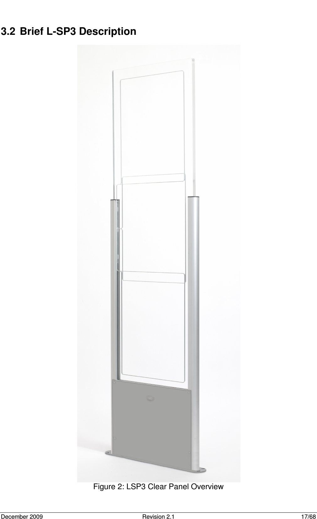
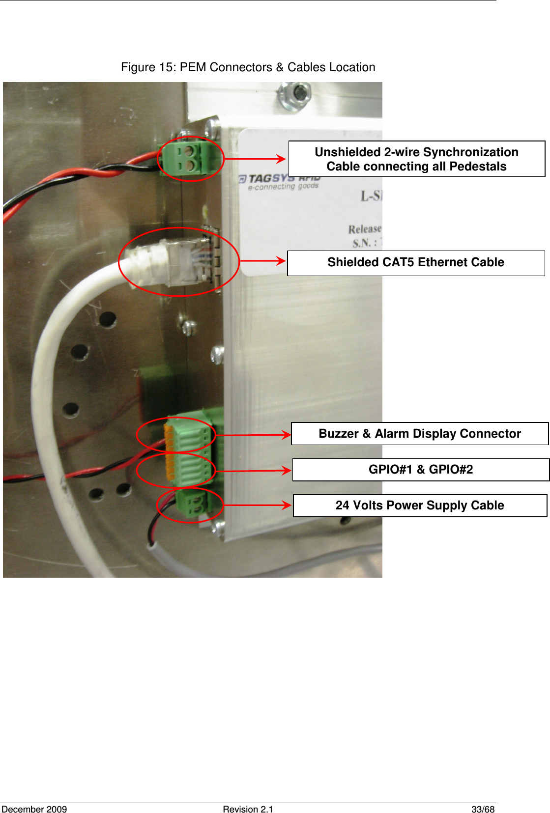
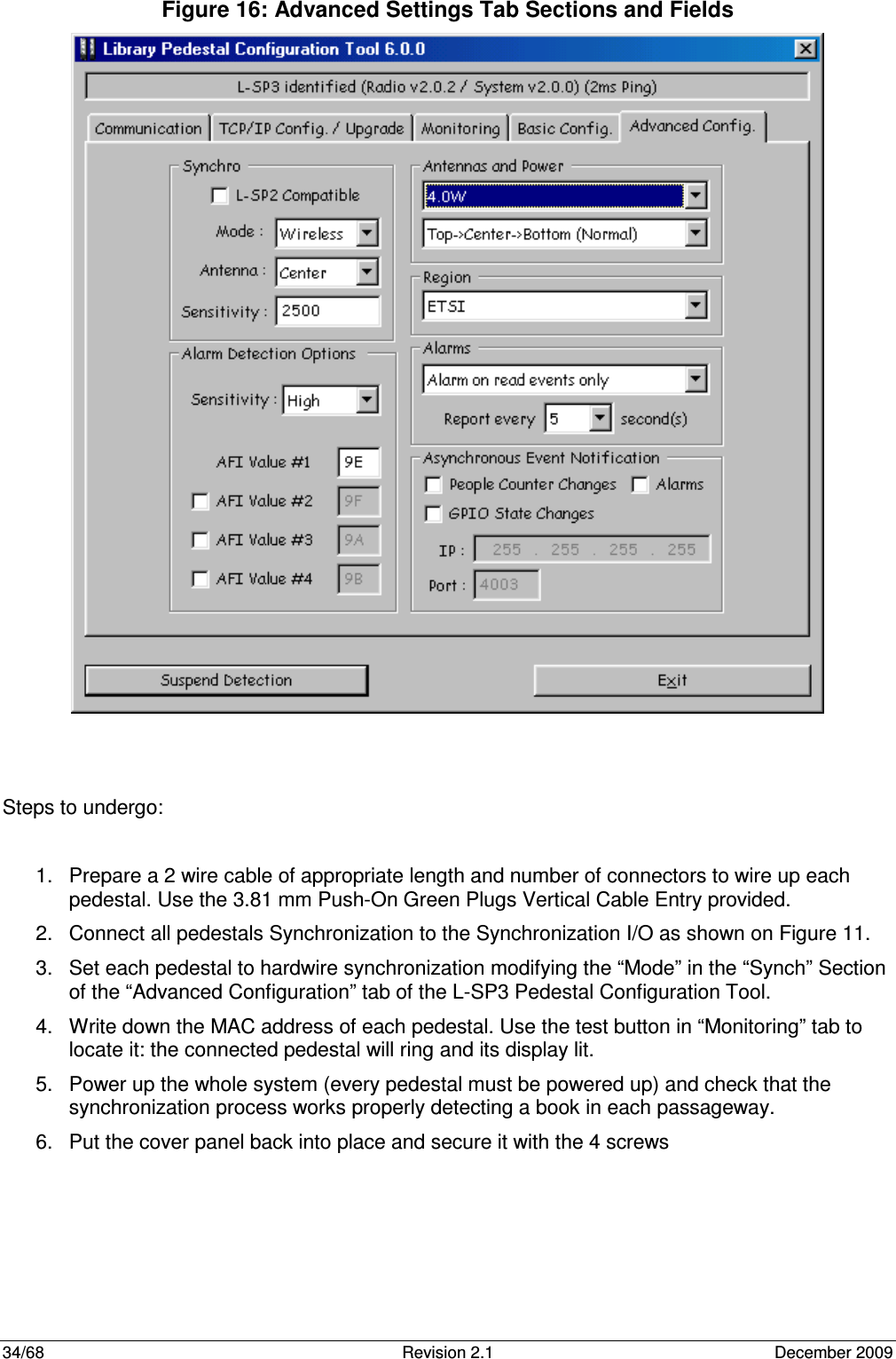
Tagsys LSP3CLEAR-L40 Security Pedestal User Manual Manual
Tagsys S.A. Security Pedestal Manual
UserManual.wiki
>
Tagsys
>
LSP3CLEAR L40 User Manual
Manual.pdf
Navigation menu
Upload a User Manual
Namespaces
Wiki Guide
HTML
PDF
Info
Views
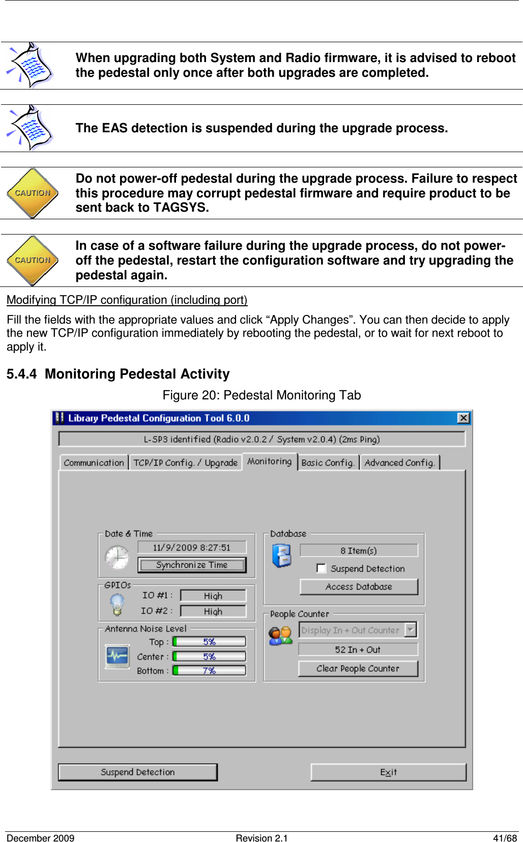
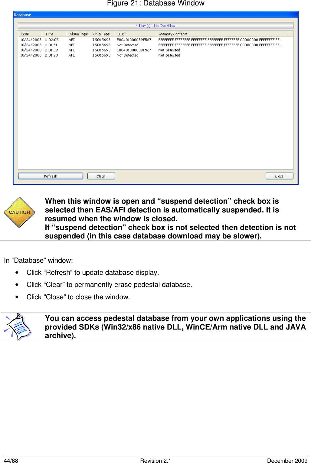
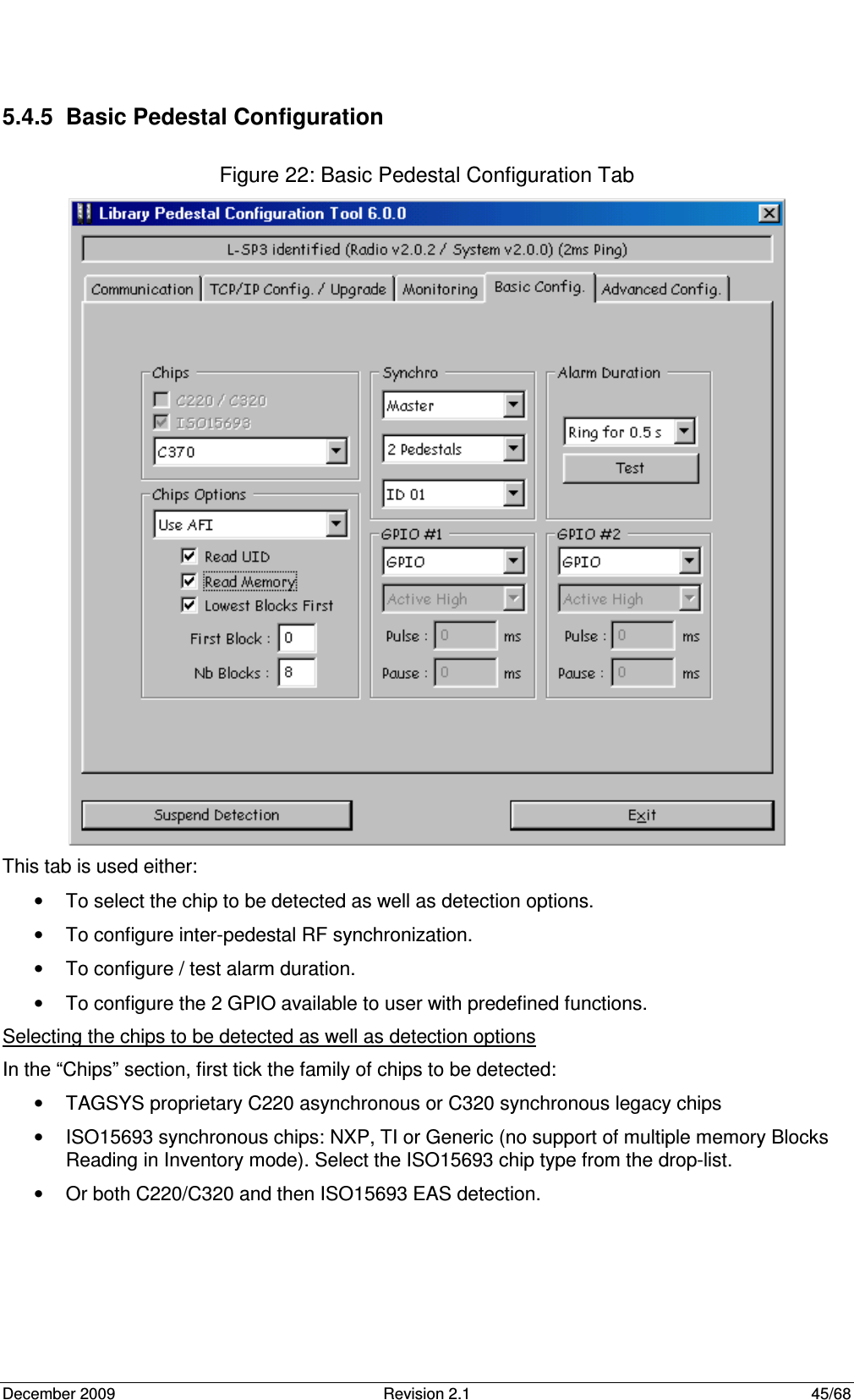
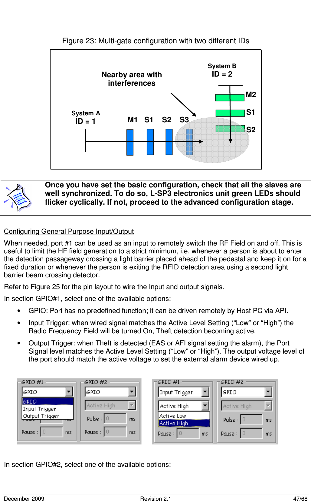
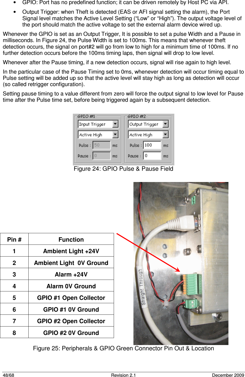
User Manual
Discussion / Help
Navigation