Tagsys MEDIOP101ETHER RFID Tag Reader User Manual Manual
Tagsys S.A. RFID Tag Reader Manual
Tagsys >
Manual
Medio P101-Ethernet
User's Guide
Revision 2.2
April 2008

Medio P101-Ethernet
2/41 Revision 2.2 April 2008
Publishing Information
Disclaimer and Limitation of Liability
All information herein is either public information or is the property of and owned solely by TAGSYS who shall have and
keep the sole right to file patent applications or any other kind of intellectual property protection in connection with such
information.
Nothing herein shall be construed as implying or granting to you any rights, by license, grant or otherwise, under any
intellectual and/or industrial property rights of or concerning any of TAGSYS’ information.
This document can be used for informational, non-commercial, internal and personal use only provided that:
the copyright notice below, the confidentiality and proprietary legend and this full warning notice appear in all copies.
this document shall not be posted on any network computer or broadcast in any media and no modification of any
part of this document shall be made.
Use for any other purpose is expressly prohibited and may result in severe civil and criminal liabilities.
The information contained in this document is provided “AS IS” without any warranty of any kind. Unless otherwise
expressly agreed in writing, TAGSYS makes no warranty as to the value or accuracy of information contained herein.
The document could include technical inaccuracies or typographical errors. Changes are periodically added to the
information herein. Furthermore, TAGSYS reserves the right to make any change or improvement in the specifications
data, information, and the like described herein, at any time.
Therefore TAGSYS assumes no liability and is not responsible for customer applications or product or software which
include TAGSYS products.
TAGSYS HEREBY DISCLAIMS ALL WARRANTIES AND CONDITIONS WITH REGARD TO THE INFORMATION
CONTAINED HEREIN, INCLUDING ALL IMPLIED WARRANTIES OF MERCHANTABILITY, FITNESS FOR A
PARTICULAR PURPOSE, TITLE AND NON-INFRINGEMENT. IN NO EVENT SHALL TAGSYS BE LIABLE, WHETHER
IN CONTRACT, TORT OR OTHERWISE, FOR ANY INDIRECT, SPECIAL OR CONSEQUENTIAL DAMAGES OR ANY
DAMAGES WHATSOEVER INCLUDING BUT NOT LIMITED TO DAMAGES RESULTING FROM LOSS OF USE,
DATA, PROFITS, REVENUES, OR CUSTOMERS, ARISING OUT OF OR IN CONNECTION WITH THE USE OR
PERFORMANCE OF INFORMATION CONTAINED IN THIS DOCUMENT.
TAGSYS does not and shall not warrant that this product/system/equipment will be resistant to all possible attacks, and
shall not incur, and disclaims, any liability in this respect. Even if each product is compliant with current security
standards in force on the date of their design, security mechanisms' resistance necessarily evolves according to the
state-of-the-art in security and notably under the emergence of new attacks. Under no circumstances shall TAGSYS be
held liable for any third party actions, and in particular in case of any successful attack against systems or equipment
incorporating TAGSYS products.
TAGSYS disclaims any liability with respect to security for direct, indirect, incidental or consequential damages that result
from any use of its products. It is further stressed that independent testing and verification by the person using the
product is particularly encouraged, especially in any application in which defective, incorrect, or insecure functioning
could result in damage to persons or property, denial of service, or loss of privacy.
© 2000-2008 TAGSYS. All rights reserved.
Microsoft, Visual C++, Windows, and Windows NT are either registered trademarks or trademarks of Microsoft
Corporation in the U.S.A. and/or other countries.
I-Code is a registered trademark of Philips.
Tag-It is a registered trademark of Texas Instruments.
Printed in France.
TAGSYS – 180 Chemin de St Lambert, 13821 LA PENNE SUR HUVEAUNE, France.
Tel: +33 (0)4.91.27.57.00 / Fax: +33 (0)4.91.27.57.01
Document Reference: DOC12085B2
Read This First
Read This First
Welcome to the TAGSYS range of products operating at the 13.56 MHz frequency. This range of
products is used to implement high-quality RFID systems for demanding applications.
This document provides information about how to install and use the Medio P101-Ethernet reader.
Audience
This document requires familiarity with RFID technology. It is intended for people in charge of
installing and using the product.
Conventions
Symbol Meaning
CAUTION: A note that advises users that a specific action could result in the loss of data or
damage the hardware.
WARNING: A note that advises users that a specific action may result in physical harm.
A note that provides additional information that helps the user perform a task or obtain the
best performance from the product.
If you need assistance
Please contact your nearest TAGSYS sales representative or the TAGSYS welcome desk at:
Telephone: +33 (0)4 91 27 57 00
Fax: +33 (0)4 91 27 57 01
E-Mail: info@tagsysrfid.com
Website: http://www.tagsysrfid.com
Contact for Comments
We welcome your feedback to help us provide high quality documentation.
For technical comments, please contact our welcome desk:
Telephone: +33 (0)4 91 27 57 00
Fax: +33 (0)4 91 27 57 01
E-Mail: info@tagsysrfid.com
Please remember to quote the Document Reference Number DOC12085B2, your job title and your
company.

Medio P101-Ethernet
4/41 Revision 2.2 April 2008
Quality Issues
TAGSYS implements stringent quality controls at all stages of its manufacturing process. However,
should you find a defect with this product, please notify your TAGSYS Quality Service
representative using the dedicated Product Return Form.
Telephone: +33 (0)4 91 27 57 36
Fax: +33 (0)4 91 27 57 02

Read This First
April 2008 Revision 2.2 5/41
Table of Contents
PUBLISHING INFORMATION __________________________________________________________ 2
DISCLAIMER AND LIMITATION OF LIABILITY__________________________________________________ 2
READ THIS FIRST ____________________________________________________________________ 3
AUDIENCE ____________________________________________________________________________ 3
CONVENTIONS _________________________________________________________________________ 3
IF YOU NEED ASSISTANCE________________________________________________________________ 3
CONTACT FOR COMMENTS _______________________________________________________________ 3
QUALITY ISSUES _______________________________________________________________________ 4
1 FOR YOUR SAFETY _______________________________________________________________ 7
1.1 GENERAL USE ____________________________________________________________________ 7
1.2 CARE AND MAINTENANCE ___________________________________________________________ 7
1.3 IMPORTANT SAFETY INFORMATION____________________________________________________ 8
1.3.1 OPERATING ENVIRONMENT ________________________________________________________ 8
2 CERTIFICATION___________________________________________________________________ 9
2.1 OCCUPATIONAL HEALTH AND SAFETY NOTICES _________________________________________ 9
2.2 REGULATORY NOTICES _____________________________________________________________ 9
2.2.1 IN EUROPE (CE AND RTTE DIRECTIVES)_____________________________________________ 9
2.2.2 FCC ID CROSS REFERENCE TABLE ________________________________________________ 10
2.2.3 IN USA (FCC DIRECTIVE)_________________________________________________________ 11
2.2.4 IN CANADA _____________________________________________________________________ 12
2.3 ROHS AND WEEE DIRECTIVES _____________________________________________________ 12
2.3.1 ROHS (RESTRICTION OF THE USES OF CERTAIN HAZARDOUS SUBSTANCES)_______________ 12
2.3.2 WEEE (WASTE ELECTRICAL AND ELECTRONIC EQUIPMENT)____________________________ 12
3 INTRODUCTION__________________________________________________________________ 13
3.1 PRODUCT DESCRIPTION ___________________________________________________________ 13
3.2 MEDIO P101-ETHERNET KEY FEATURES______________________________________________ 13
3.3 DELIVERY _______________________________________________________________________ 14
4 INSTALLING THE READER________________________________________________________ 15
4.1 READER CONNECTIONS____________________________________________________________ 15
4.1.1 FRONT PANEL __________________________________________________________________ 15
4.1.2 REAR PANEL ___________________________________________________________________ 16
4.2 COMMUNICATE WITH ETHERNET INTERFACE ___________________________________________ 17
4.2.1 ETHERNET MODULE DESCRIPTION _________________________________________________ 18
4.2.2 DEFAULT READER NETWORK SETTINGS _____________________________________________ 20
4.2.3 ADDP PROCEDURE (ADVANCED DIGICONNECT DISCOVERY DEVICE)_____________________ 21
4.3 COMMUNICATE WITH THE USB INTERFACE ____________________________________________ 23
4.3.1 WINDOW 98® USB DRIVERS INSTALLATION __________________________________________ 23

Medio P101-Ethernet
6/41 Revision 2.2 April 2008
4.3.2 WINDOWS XP USB DRIVERS INSTALLATION __________________________________________ 24
5 PX EXPLORER ___________________________________________________________________ 25
5.1 INSTALLING PX EXPLORER _________________________________________________________ 25
5.2 RUNNING PX EXPLORER ___________________________________________________________ 27
5.2.1 USB COMMUNICATION ___________________________________________________________ 27
5.2.2 ETHERNET COMMUNICATION ______________________________________________________ 27
5.3 READING AND WRITING A TAG ______________________________________________________ 28
5.4 DOWNLOADING A FIRMWARE________________________________________________________ 29
6 STAND-ALONE MODE ____________________________________________________________ 31
6.1 STAND-ALONE MODE FEATURES ____________________________________________________ 31
6.1.1 CUSTOMIZED ASCII MESSAGE FORMAT _____________________________________________ 31
6.1.2 REPETITION OPTION _____________________________________________________________ 32
6.1.3 TRIGGER INPUT _________________________________________________________________ 33
6.1.4 OUTPUT SETTINGS ______________________________________________________________ 33
6.2 STAND-ALONE MODE SETTINGS _____________________________________________________ 33
6.2.1 USING PX EXPLORER ____________________________________________________________ 34
6.3 DISABLING STAND-ALONE MODE ____________________________________________________ 34
7 CONNECTING PERIPHERAL DEVICES _____________________________________________ 35
7.1 USING THE UNIVERSAL INPUT PIN____________________________________________________ 35
7.2 USING THE UNIVERSAL OUTPUT PIN__________________________________________________ 35
7.2.1 OUTPUT WIRING ________________________________________________________________ 35
7.3 I/O ELECTRICAL SIGNAL REQUIREMENTS _____________________________________________ 36
8 TECHNICAL SPECIFICATIONS ____________________________________________________ 37
9 ELECTRICAL CHARACTERISTICS _________________________________________________ 38
9.1 ABSOLUTE MAXIMUM RATINGS______________________________________________________ 38
9.2 DC CHARACTERISTICS ____________________________________________________________ 38
10 WARRANTY CONDITIONS _______________________________________________________ 39
10.1 WARRANTY _____________________________________________________________________ 39
10.2 WARRANTY EXCLUSIONS _________________________________________________________ 39
10.2.1 GENERAL PROVISIONS __________________________________________________________ 40
10.2.2 HOW TO RETURN DEFECTIVE PRODUCTS ___________________________________________ 40

For Your Safety
April 2008 Revision 2.2 7/41
1 For Your Safety
1.1 General Use
The Medio P101-Ethernet is designed to be reliable and to provide years of trouble-free service.
Please observe the following general tips:
Take care not to scratch the device. Keep the device clean. When working with the device,
use only TAGSYS-approved accessories.
This device is not waterproof and should not be exposed to rain or moisture. Under extreme
conditions, water may enter the circuitry.
Protect the device from extreme temperatures. For example, do not place the device in a
windowed area where the sun may cause extreme temperatures, and keep it away from
heaters and other heat sources.
Do not store or use the device in any location that is extremely dusty, damp, or wet.
Use a soft, damp cloth to clean the device. If the surface of the device becomes soiled,
clean it with a soft cloth moistened with a diluted window-cleaning solution.
1.2 Care and Maintenance
This device is a product of superior design and should be handled with care. The suggestions
below will further increase the lifetime of this device.
• Keep the device and all parts and accessories out of the reach of small children.
• Keep the device dry. Precipitation, humidity and liquids contain minerals that will corrode
electronic circuits.
• Do not use or store the device in dusty, dirty areas. Its moving parts can be damaged.
• Do not store in hot areas. High temperatures can shorten the life of electronic devices,
damage batteries and warp or melt certain plastics.
• Do not store in cold areas. When the device warms up (to its normal temperature), moisture
can form inside the device, which may damage electronic circuit boards.
• Do not attempt to open the device. Non-professional handling of the device may damage it.
• Handle the device with care. Shocks may break internal circuit boards.
• Do not clean the device with harsh chemicals, cleaning solvents or strong detergents.
Gently wipe the device with a soft cloth slightly dampened in a mild soap-and-water
solution.
• Do not paint the device. Paint may clog the device’s moving parts and prevent proper
operation. Paint with metallic contents may limit device performances.
• If the device or any accessory are not working properly, take it to your nearest qualified
TAGSYS representative.

Medio P101-Ethernet
8/41 Revision 2.2 April 2008
1.3 Important Safety Information
1.3.1 Operating Environment
When connecting the device or any accessory to another device, read its user’s guide for detailed
safety instructions. Do not connect incompatible products.
To avoid contact with electrical current:
• Never install electrical wiring during an electrical storm.
• Never install an ethernet connection in wet locations unless that connector is specifically
designed for wet locations.
• Use caution when installing or modifying ethernet lines.
• Use a screwdriver and other tools with insulated handles.
• You and those around you should wear safety glasses or goggles.
• Do not place ethernet wiring or connections in any conduit, outlet or junction box containing
electrical wiring.
• Installation of inside wire may bring you close to electrical wire, conduit, terminals and other
electrical facilities. Extreme caution must be used to avoid electrical shock from such
facilities. You must avoid contact with all such facilities.
• Ethernet wiring must be at least 6 feet from bare power wiring or lightning rods and
associated wires, and at least 6 inches from other wire (antenna wires, doorbell wires, wires
from transformers to neon signs), steam or hot water pipes, and heating ducts.
• Do not place an ethernet connection where it would allow a person to use an ethernet
device while in a bathtub, shower, swimming pool, or similar hazardous location.
• Protectors and grounding wire placed by the service provider must not be connected to,
removed, or modified by the customer.
• Do not touch non-insulated ethernet wiring if lightning is likely!
Any external communications wiring you may install needs to be constructed to all relevant
electrical codes. In the United States this is the National Electrical Code Article 800. Contact a
licensed electrician for details.
As with all RF equipment, users are advised that the equipment should only be used in its normal
operating position.
Certification
April 2008 Revision 2.2 9/41
2 Certification
2.1 Occupational Health and Safety Notices
TAGSYS Medio P101-Ethernet reader has been designed and tested to be in conformity with the
European Standard EN 50364 “Limitation of human exposure to electromagnetic fields from
devices used in Electronic Article Surveillance (EAS), Radio Frequency Identification (RFID) and
similar applications” in conjunction with the European Standard EN 50357 describing how to
evaluate the exposure level.
2.2 Regulatory Notices
An RFID system typically composed of an RF emission device such as the Medio P101-Ethernet
connected to an antenna is subject to national regulations that may differ by country.
One important item to consider is the maximum permissible magnetic field intensity at a distance of
10 meters from the antenna that must not exceed 60 dBµA/m in Europe and at a distance of 30
meters from the antenna that must not exceed 84 dBµA/m in US.
The Medio P101-Ethernet meets these limits.
2.2.1 In Europe (CE and RTTE Directives)
The Medio P101-Ethernet complies (CE Declaration of Conformity granted) with the European
EMC directive.
The Medio P101-Ethernet complies with the requirements of the Telecommunication Terminal
Equipment Act (FTEG) and the RTTE Directive 1995/5/EC.
It is the responsibility of the TAGSYS Reseller to install the Medio P101-Ethernet as described in
this Reference guide or TAGSYS Documentation.
Any modification of the Medio P101-Ethernet is prohibited without the written consent of TAGSYS.
Unauthorized modifications may void the conformity of the equipment to CE and RTTE Directives
and will void the TAGSYS warranty.
It is the responsibility of the TAGSYS Partner to install the Medio P101-Ethernet as
described in this User’s Guide or in TAGSYS Documentation.
If a Medio P101-Ethernet is further integrated in a different product, it is the responsibility of
the manufacturer of this complementary product to obtain the required approvals for this
product.

Medio P101-Ethernet
10/41 Revision 2.2 April 2008
2.2.2 FCC ID Cross Reference Table
It is the responsibility of the TAGSYS Partner to install the Medio P101-Ethernet as described in
the table below, taking care of only installing the right antenna configuration with the right power
settings.
Antenna
Configuration Outside
Dimension Channel Setting Max. Output
Power FCC ID
LSA 4 230X262mm Single Channel 1W QHKMEDIOP101ETHER
Aero LF SHD Ø 25mm Single Channel 1W QHKMEDIOP101ETHER
Aero LB
Antenna 250X250mm Single Channel 1W QHKMEDIOP101ETHER
L-W1 Antenna Ø 100mm Single Channel 1W QHKMEDIOP101ETHER

Certification
April 2008 Revision 2.2 11/41
2.2.3 In USA (FCC Directive)
The Medio P101-Ethernet has been designed to comply with Part 15 of the FCC Rules.
Furthermore typical configurations based on the use of Single Antenna like Aero LB at 1W, LW 1
at 1W, Aero LF SHD at 1W and LSA 4 at 1 W, have been successfully tested with Part 15 of the
FCC rules (FCC ID Numbers are listed on all system-mounted TAGSYS Antennas).
Medio P101-Ethernet
WARNING TO USERS IN THE UNITED STATES
FEDERAL COMMUNCIATIONS COMMISSION (FCC) RADIO
INTERFERENCE STATEMENT 47 CFR Section 15.105(b)
This equipment has been tested and found to comply with the limits for a Class B digital device,
pursuant to Part 15 of the FCC Rules. These limits are designed to provide reasonable protection
against harmful interference in a residential installation. This equipment generates, uses and can
radiate radio frequency energy and if not installed and used in accordance with the instructions
may cause harmful interference to radio communications. However, there is no guarantee that
interference will not occur in a particular installation. If this equipment does cause harmful
interference to radio or television reception, which can be determined by turning the equipment off
and on, the user is encouraged to try to correct the interference by one or more of the following
measures:
▪ Reorient or relocate the receiving antenna.
▪ Increase the separation between the equipment and receiver.
▪ Connect the equipment into an outlet on a circuit different to that to which the receiver is
connected.
▪ Consult the dealer or an experienced radio/TV technician for help.
NO UNAUTHORIZED MODIFICATIONS
47 CFR Section 15.21
CAUTION: This equipment may not be modified, altered, or changed in any way without signed
written permission from TAGSYS SA. Unauthorized modification may void the equipment
authorization from the FCC and will void the TAGSYS warranty.
ANTENNA REQUIREMENT
47 CFR Section 15.203
CAUTION: This equipment must be professionally installed. The installer shall be responsible for
ensuring that the proper antenna is employed so that the limits in this part are not exceeded. Non-
professional installation or installation of the equipment with an improper antenna may void the
equipment authorization from the FCC and will void the TAGSYS warranty.
Operation is subject to the following two conditions: (1) The system devices may not cause harmful
interference, and (2) The system devices must accept any interference received, including
interference that may cause undesired operation.
Medio P101-Ethernet
12/41 Revision 2.2 April 2008
2.2.4 In Canada
To reduce potential radio interference to other users, the antenna type and its gain should be so
chosen that the equivalent isotropically radiated power (e.i.r.p) is no more than that permitted for
successful communication.
This device has been designed to operate with the antennas listed below, and having a maximum
gain of -35 dBi. Antenna not included in this list or having a gain greater than -35 dBi are striclly
prohibited for use with this device. The require antenna impedance is 50 ohms.
Aero LB, LW 1, Aero LF SHD and LSA 4 antennas meet this requirement with a gain less than
-35dBi.
2.3 RoHS and WEEE Directives
2.3.1 RoHS (Restriction of the uses of certain Hazardous Substances)
TAGSYS certifies that this product is compliant with the European Directive 2002/95/EC for the
restriction in Electric and Electronic Equipments (RoHS) of the use of the following hazardous
substances:
• Lead
• Mercury
• Cadmium
• Hexavalent Chromium
• Polybrominated biphenyl flame retardants
• Polybrominated diphenyl ether flame retardants
This declaration is based on information provided by our suppliers and subcontractors.
2.3.2 WEEE (Waste Electrical and Electronic Equipment)
This product bears the selective sorting symbol for waste electrical and
electronic equipment (WEEE)
This means that this product must be handled pursuant to European
Directive 2002/96/EC in order to be recycled or dismantled to minimize
its impact on the environment.
For further information, please contact your local or regional authorities.
Introduction
April 2008 Revision 2.2 13/41
3 Introduction
3.1 Product Description
The Medio P101-Ethernet is a Medium Range 13.56 MHz RFID reader designed for Library,
Textile Rental and I&L applications. The Medio P101-Ethernet has been designed to be used in
combination with Aero LB, LW 1, Aero LF SHD and LSA 4 antennas that comply with FCC and CE
rules. The Medio P101-Ethernet can decode C210, C220, C240, C320, C370(ISO 15693), C270(I-
Code1)and I-Code ePC and I-Code UID tags.
Thanks to its small size, the Medio P101-Ethernet can be used either in desktop configuration or
easily integrated in self check stations.
The Medio P101-Ethernet is equipped with the following communication interfaces:
• USB 1.1 communication link (prioritary)
• Ethernet (Raw TCP serial communication)
3.2 Medio P101-Ethernet Key Features
Table 1: Medio P101-Ethernet Key Features
Description Medio P101-Ethernet
Operating Frequency 13.56 MHz
Firmware Chips
Library C220, C320, C370(ISO 15693)
Textile
rental
C210, C240, C270(Philips I-
Code1), C370(ISO15693)
Compatibility
(depends on application
firmware)
I&L
C270 (Philips I-Code1), C370
(ISO15693), I-Code EPC/I-
Code UID
Serial Link USB 1.1 or Ethernet raw TCP serial
communication
Firmware Downloadable Yes

Medio P101-Ethernet
14/41 Revision 2.2 April 2008
3.3 Delivery
The Medio P101-Ethernet Tag Reader kit contains the following items:
Table 2: Package Contents
Quantity Item
1 Medio P101-Ethernet reader
1 SMA/BNC adaptor
1 Set of rubber feet
1 USB cable
1 I/O connector
1 Wall fixing accessory
1 12 V power supply
1 CD-ROM including:
• Medio P101-Ethernet User’s Guide, Command Set
• USB drivers for Win32 X86 platforms
• User-friendly Px Explorer software provided for test and debug operations on
Windows® 9x, NT®, 2000 and XP platforms
• TAGSYS Software Development Kits including
o Medio STX Dll package
o Library SDK including Dlls and ActiveX control
o Java Package
• Digiconnect Ethernet module integration kit
• Adobe Acrobat reader version 6&7
1 Welcome Letter / Product Return Form
Installing the Reader
April 2008 Revision 2.2 15/41
4 Installing the Reader
This section describes how to install the Medio P101-Ethernet reader.
4.1 Reader Connections
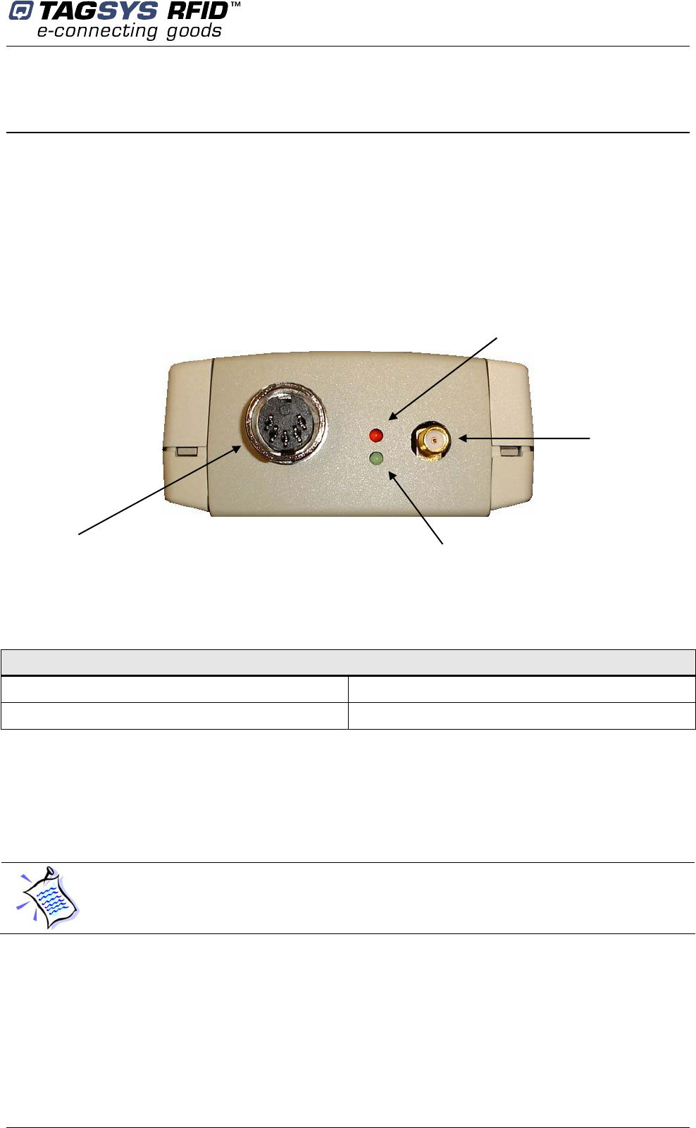
4.1.1 Front Panel
The front panel is dedicated to RF and I/O connectors:
Figure 1: Front panel
• RF antenna connector:
Any of the following antennas can be connected to the standard SMA connector:
Antennas that apply to CE rules
• L-W1 • Aero LI
• TR-HA1 • L-SA3
• Leds
The red LED lights on continuously when the power supply voltage is correct.
If the red LED is blinking the power supply voltage is insufficient.
During firmware downloading the red Led is blinking.
The green Led is turned on when the output I/O connector is active.
I/O
connector Green Led
Red Led
RF antenna
connector
Medio P101-Ethernet
16/41 Revision 2.2 April 2008
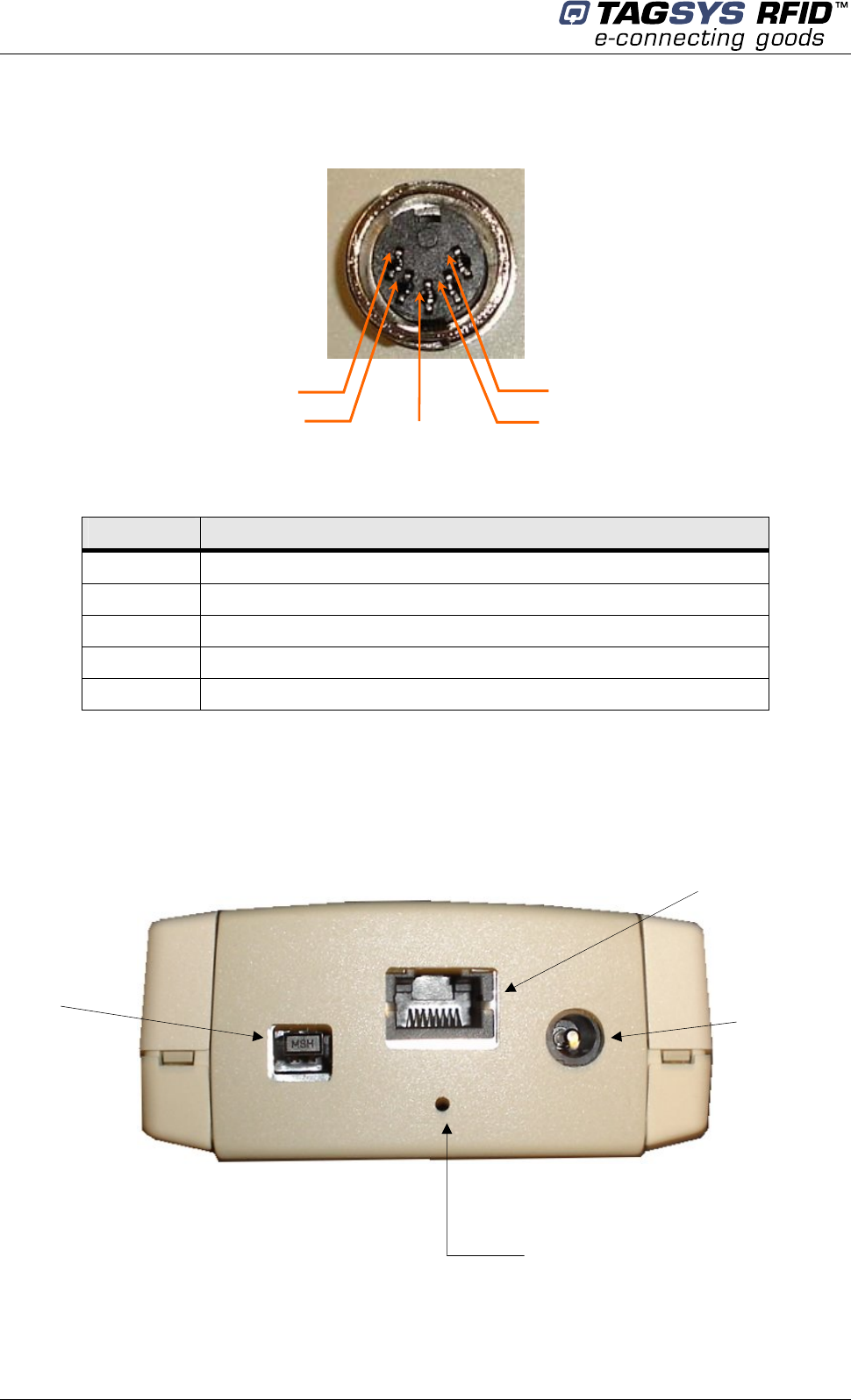
• I/O connector
Table 2: J3 Wiring
Pin number Signals
1 Output
2 Supply output (12V with 470 Ω serial resistor)
3 Universal input
4 Ground
5 Ground
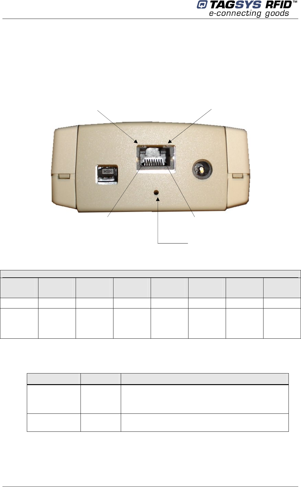
4.1.2 Rear Panel
The rear panel is dedicated to power supply and communication connectors.
Figure 3: Rear panel
# 1
# 4
# 3
# 5 # 2
12V DC
Power
supply
connector J2
Connector to
Ethernet module
USB
connector
Reset button for
Ethernet module
only
Installing the Reader
April 2008 Revision 2.2 17/41
• Ethernet module connector
A shielded RJ 45 connector (Please refer to the Ethernet network cabling rules)
• Power supply connector J2
2.5mm Jack type (positive connection on the center pin)
• Reset button
Reset button only used for Ethernet module (Please see Chapter 4.2 for more details)
• USB connector
USB connector type B
When USB communication link is active (plugged and powered), the Ethernet module is
turned off.
4.2 Communicate with Ethernet Interface
Preliminary checking:
- USB cable must be unplugged to ensure that the Ethernet Module is turned on
- Shielded ethernet cable must be correctly connected to the rear panel
The embedded Ethernet module is the DigiConnect -ME. Any information on this module is
available on the CDROM in the directory “\DigiConnect IntegrationKit\Documentation” or on the
DigiConnect WEB pages at “www.digi.com”.
Please read the DigiConnect User’s Guide to have an overview of the module characteristics.
The following explanations will give you the first steps to run the reader. Advanced functionalities
can be found in the DigiConnect User’s Guide.
Medio P101-Ethernet
18/41 Revision 2.2 April 2008
4.2.1 Ethernet Module Description
Ethernet Interface Pin Assignments
Pin
1
Pin
2
Pin
3
Pin
4
Pin
5
Pin
6
Pin
7
Pin
8
TXD+ TXD- RXD+ EPWR+ EPWR+ RXD- EPWR- EPWR-
Transmit
Data +
Transmit
Data -
Receive
Data +
Power
From
Switch +
Power
From
Switch +
Receive
Data -
Power
From
Switch -
Power
From
Switch -
• LED description
LED Color Description
Network Link Yellow
This LED stays on continuously when a link has been
detected.
Note that this LED is turned off during device starting up.
Network Activity Green This LED monitors the network traffic. It turns on when any
traffic is detected.
Network Activity LED
Network Link LED
Reset button for
Ethernet module
only
Pin 8 Pin 1
Installing the Reader
April 2008 Revision 2.2 19/41
• Reset Procedure
To reset the Ethernet module 2 procedures are available:
- Reboot the device: it is used to reinitialize the communication with your network.
- Reset the device to TAGSYS default factory settings: it is used when you can no more
communicate with the reader due to wrong WIFI settings.
Both reset procedures are available by software via the WEB or TELNET interface.
Reset Description
Reboot While the reader is supplied, push the reset button with a thin object and
release it. Wait for the reader start up.
Reset To
TAGSYS Factory
defaults
This procedure reset the entire device configuration (including network
settings) to the TAGSYS factory defaults.
- Unplug the reader power supply
- Push the reset button
- Plug the reader power supply
- Keep the reset button pressed until the yellow LED blinks once and
3 times.
- Release the reset button
- Unplug the power supply and plug it again
- Wait for reader start up.
Medio P101-Ethernet
20/41 Revision 2.2 April 2008
• Safety Statements
To avoid contact with electrical current:
- Never install electrical wiring during an electrical storm
- Never install an Ethernet connection in wet locations unless that connector is
specifically designed for wet locations
- Use caution when installing or modifying Ethernet lines
- Do not place Ethernet wiring or connections in any conduit, outlet or junction
box containing electrical wiring
- Installation of inside wire may bring you close to electrical wire, conduit,
terminals and other electrical facilities. Extreme caution must be used to avoid
electrical shock from such facilities. You must avoid contact with all such
facilities
- Ethernet wiring must be at least 6 feet from bare power wiring or lightning rods
and associated wires, and at least 6 inches from other wire (antenna wires,
doorbell wires, wires from transformers to neon signs), steam or hot water
pipes, and heating ducts
- Do not place an Ethernet connection where it would allow a person to use an
Ethernet device while in a bathtub, shower, swimming pool, or similar
hazardous location
- Protectors and grounding wire placed by the service provider must not be
connected to, removed, or modified by the customer
- Do not touch uninsulated Ethernet wiring if lightning is likely!
Any external communications wiring you may install needs to be constructed to all
relevant electrical codes. In the United States this is the National Electrical Code Article
800. Contact a licensed electrician for details.
4.2.2 Default Reader Network Settings
You will not be able to configure any network setting before no Ethernet link has been detected.
It depends to you to engage the reader with your Ethernet network correctly first.
Additionally, the default settings for the reader network configuration are:
- DHCP : Off
- Static IP Address : 192.168.0.2
- Subnet Mask : 255.255.255.0
- Default Gateway : 0.0.0.0
Installing the Reader
April 2008 Revision 2.2 21/41
You can now configure your Ethernet network to link the reader or follow the ADDP procedure to
change the basic network IP settings.
If you decide to configure your Ethernet network to meet the default settings of the reader, you
can check your system is operational by pinging the reader using then “ping 192.168.0.2”
MSDOS command prompt.
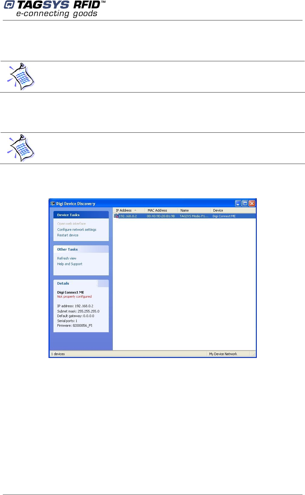
4.2.3 ADDP procedure (Advanced DigiConnect Discovery Device)
Firewalls may block ADDP broadcast protocol. Please turn your firewall off for initialization to
avoid issues (This includes Windows XP firewall)
Run “\DigiConnect Integration Kit\dgdiscvr.exe” program available on the product CDROM. The
following window pops up:
If no reader appears in the Discovery windows, check that:
- no firewall program is running
- the reader is properly linked with your Ethernet network
If the reader is not properly configured, double-click on the device. The following window pops up:
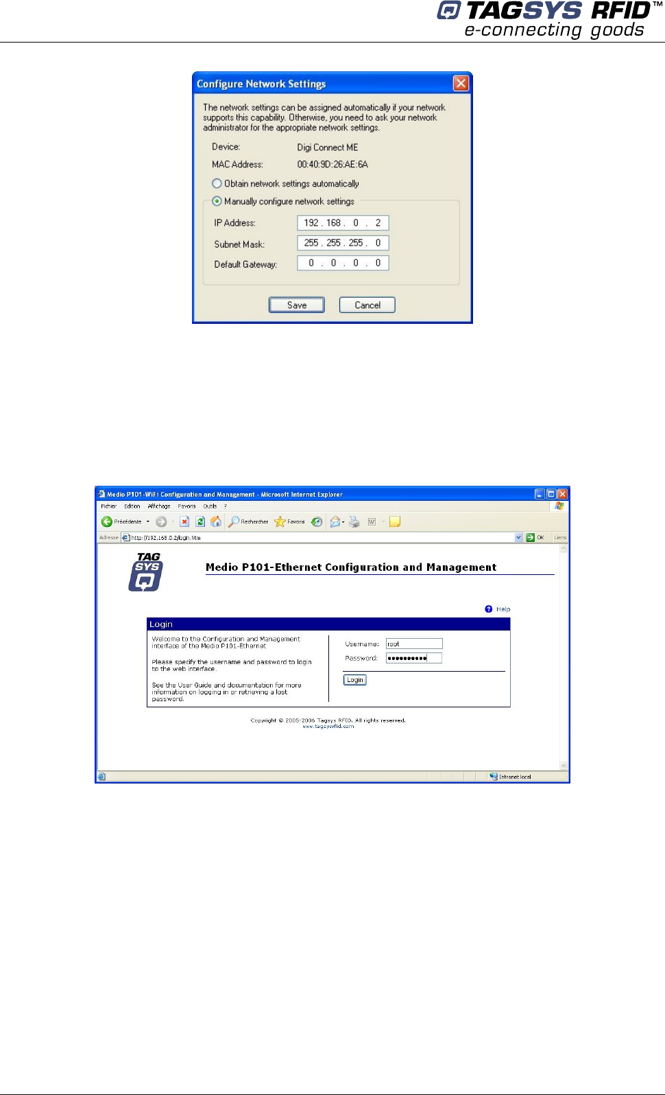
Medio P101-Ethernet
22/41 Revision 2.2 April 2008
Select the correct Static IP, Subnet mask and Default Gateway or check the automatic setting in
case a DHCP protocol is available on your network.
Then, click Save. The reader starts to rebooting and the window closes.
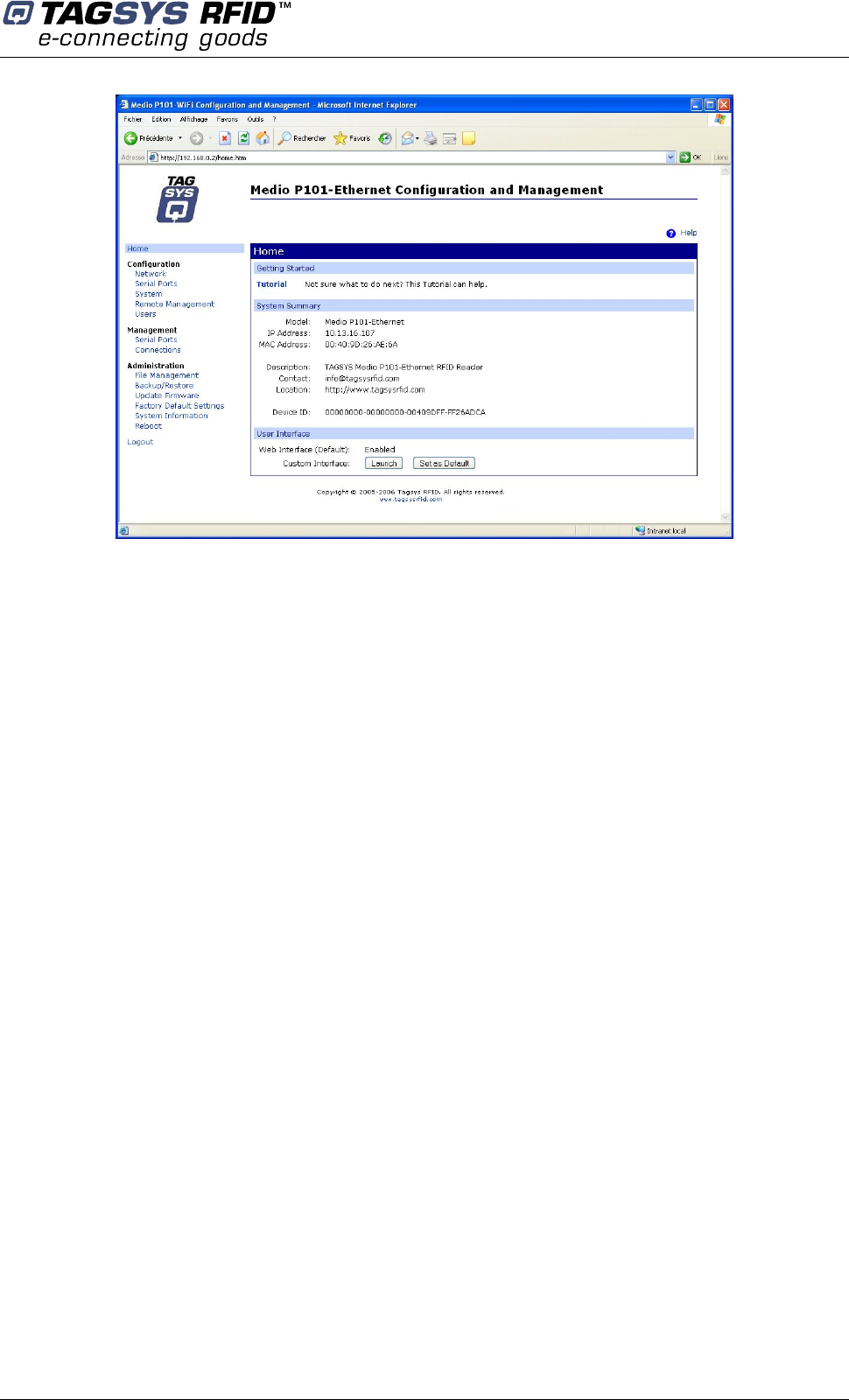
Back to the main window, double-click once again on the device. The WEB interface opens in the
Internet Explorer browser (caution to the proxy settings of your internet browser connection, it must
be set to allow access to this device).
Log on to the configuration WEB page device:
- username : root
- password : tagsysrfid
Follow DigiConnect ME user’s guide to configure the device.
Installing the Reader
April 2008 Revision 2.2 23/41
4.3 Communicate with the USB Interface
At first connection to the PC USB port, Windows® will detect the TAGSYS Medio P101-Ethernet
reader and will ask you for drivers installation. USB drivers are located into the USB Drivers folder
on the product CD-Rom.
Two drivers must be installed:
- The first one is the direct driver, which provides direct access to USB device via a dynamic
link library (DLL).
- The second one is the virtual COM port (VCP) driver. The VCP driver emulates a standard
PC COM port.
4.3.1 Window 98® USB Drivers Installation
Power up and connect your Medio P101-Ethernet to a spare USB port on your PC. This should
bring up a “Building Driver Information Database” followed by the Windows Add New Hardware
Wizard.
Click “Next” to proceed with the installation
Select “Search for the best driver for your device” and then click “Next”
Select “Specify a location” and click the Browse button to select the USB Drivers folder on
the Product CR-Rom. Once the files have been located, click “Next” to proceed with the
installation
Click “Next” to install the device
Windows® should then display a message indicating that the installation was successful.
Click “Finish” to complete the installation.
To confirm that the installation has completed successfully, open the Device Manager and select
“View devices by type”. The TAGSYS Medio P101 appears as a USB device connected to a USB
port
The next step is to install the VCP drivers.
Medio P101-Ethernet
24/41 Revision 2.2 April 2008
Power up and connect your Medio P101-Ethernet to a spare USB port on your PC. This should
bring up a “Building Driver Information Database” followed by the Windows Add New Hardware
Wizard.
Select “Search for the best driver for your device” and then click “Next”
Select “Specify a location” and click the Browse button to select the USB Drivers folder on
the Product CR-Rom. Once the files have been located, click “Next” to proceed with the
installation
Click “Next” to install the device
Windows® should then display a message that the installation of the serial converter driver
was successful. The COM port emulation driver must now be installed. Click “Finish” to
complete the installation.
To confirm that the installation has completed successfully, open the Device Manager and select
“View > devices by type”. The TAGSYS Medio P101 appears as an additional COM port.
4.3.2 Windows XP USB Drivers Installation
Power up and connect your Medio P101-Ethernet to a spare USB port on your PC. This will launch
the Windows Found New hardware Wizard
Select “No, not this time” and click next to proceed with the installation
Select “Install from a list or specific location (Advanced)” and then click “Next”
Select “Search for the best driver in these locations” and click the Browse button to select
the TAGSYS USB Drivers folder on the Product CR-Rom. Then click “Next” to proceed.
Windows should then display a message indicating that the installation was successful.
Click Finish to complete the installation
To confirm that the installation has completed successfully, open the Device Manager and select
“View > Devices by type”. The TAGSYS Medio P101 appears as a USB device connected to a
USB port.
The next step is to install the VCP drivers.
Power up and connect your Medio P101-Ethernet to a spare USB port on your PC. This will launch
the Windows Found New Hardware Wizard
Select “No, not this time” and click next to proceed with the installation
Select “Install from a list or specific location (Advanced)” and then click “Next”
Select “Search for the best driver in these locations” and click the Browse button to select
the USB Drivers folder on the Product CR-Rom. Then click “Next” to proceed.
Windows should then display a message indicating that the installation was successful.
Click Finish to complete the installation. This has installed the serial converter. The COM
port emulation driver must be installed after this has completed.
After clicking “Finish”, the Found New Hardware Wizard will continue by installing the COM
port emulation driver.
To confirm that the installation has completed successfully, open the Device Manager and select
“View > Devices by type”. The TAGSYS Medio P101 appears as an additional COM port.
When the USB cable is plugged and communication is active, the ETHERNET module is
turned off.
Px Explorer
April 2008 Revision 2.2 25/41
5 Px Explorer
The Medio P101-Ethernet reader is delivered with the Px Explorer software tool intended to easily
setup the reader, test it and perform reading and writing operations according to the antenna and
type of tag to be used. In addition, Px Explorer can display additional information such as the
Product Reference and Firmware version and revision. This section describes how to start with Px
Explorer.
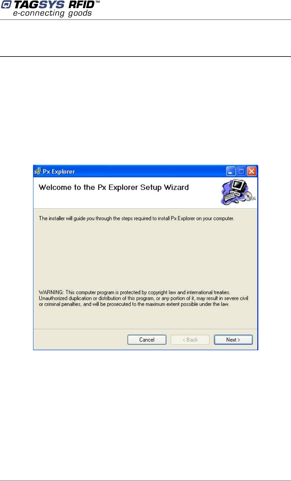
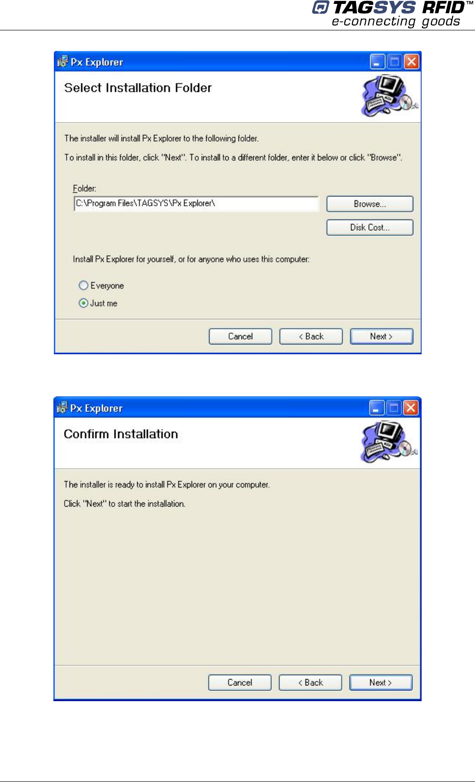
5.1 Installing Px Explorer
To install Px Explorer software, insert the product CD-ROM into the disk drive on your PC and run
the Setup from the Medio P101 – Software Suite\ Tools\Px Explorer 1-5-7 folder and click “Next”
Click the “Browse” button if you want to choose a specific installation folder.
Medio P101-Ethernet
26/41 Revision 2.2 April 2008
Once the correct folder is selected, click “Next”
Click “Next” to start the installation process. A shortcut will be created on your desktop and a
program group will be created in the start menu.
Px Explorer
April 2008 Revision 2.2 27/41
5.2 Running Px Explorer
5.2.1 USB Communication
Before launching Px Explorer be sure which COM port number is assigned to the TAGSYS Medio
P101-Ethernet reader. Open the Device Manager and select “View > Devices by type”.
The COM port number is assigned to the Medio P101.
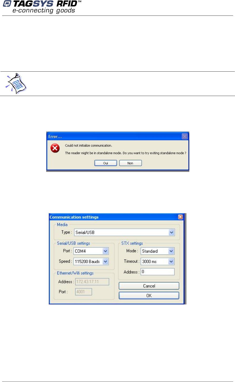
Power up the Medio P101-Ethernet and connect the USB cable to both your PC and the Medio
P101-Ethernet. Run Px Explorer. If the following window is displayed click yes.
Open the Communication Settings window (CTRL+C) and check the type of the media, the COM
port number and the communication speed. The default communication speed for the Medio P101-
Ethernet is 115200 Bauds.
Set the STX setting mode to Fast to increase performances and click OK. Now Px Explorer is
ready to communicate with your Medio P101-Ethernet.
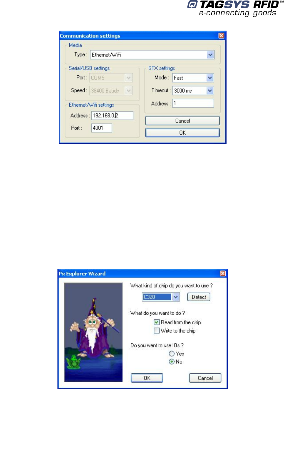
5.2.2 Ethernet Communication
Before running Px Explorer, be sure that the Medio P101-Ethernet module is power up and
correctly linked to your Ethernet network.
Open the communication setting window (CRTL+C) and check that the media type is selected to
Ethernet/WIFI as shown below.
Medio P101-Ethernet
28/41 Revision 2.2 April 2008
Enter the correct reader IP address.
Check the port number value and change it to the correct value in case the default raw TCP port
value of the Medio P101-Ethernet reader has been modified.
Set the STX setting mode to Fast to increase performances and click OK.
5.3 Reading and Writing a Tag
Px Explorer includes a Wizard function used to guide you each step of how to read or program a
tag. We recommend using the Wizard function for users who are not familiar with all Px Explorer
capabilities and features.
Click on the Wizard icon (magic wand) to open the Px Explorer Wizard dialog box.
Select the type of chip from the drop–down menu or place the tag on the antenna and click the
“Detect “ button to automatically detect the tag type.
Select the desired operation (Read or Write) and then click OK. All the necessary windows to
perform the desired action will be automatically displayed on the screen.
Px Explorer
April 2008 Revision 2.2 29/41
For more details concerning Px Explorer select the info menu and click Help (CTRL+H) to display
the Px Explorer User’s Guide.
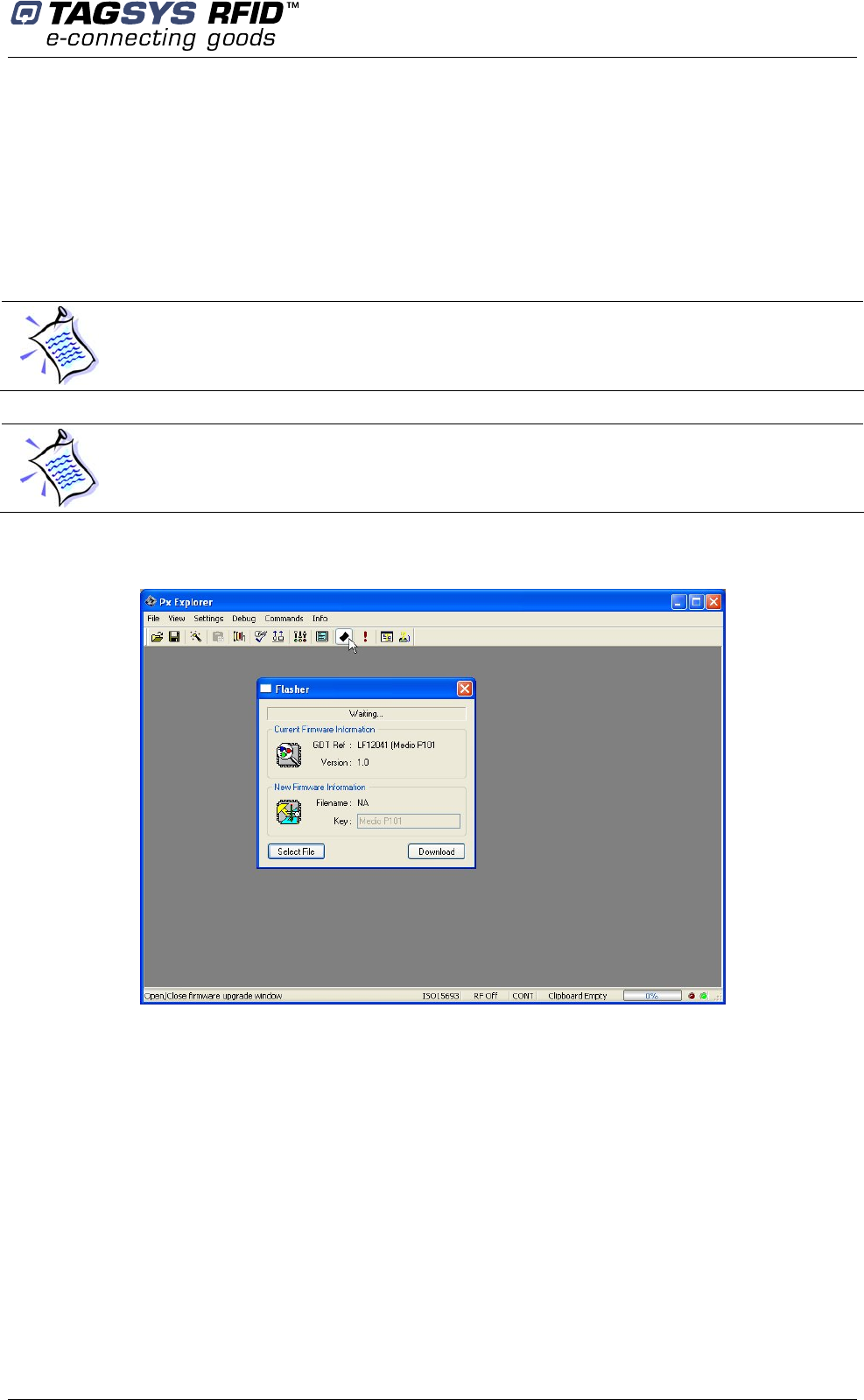
5.4 Downloading a firmware
Use Px Explorer to download a new firmware. When a communication is established with the
reader, click on the upgrade firmware button
By default Library firmware is already loaded.
The firmware upgrade can be done either using the USB or Ethernet communication interface.
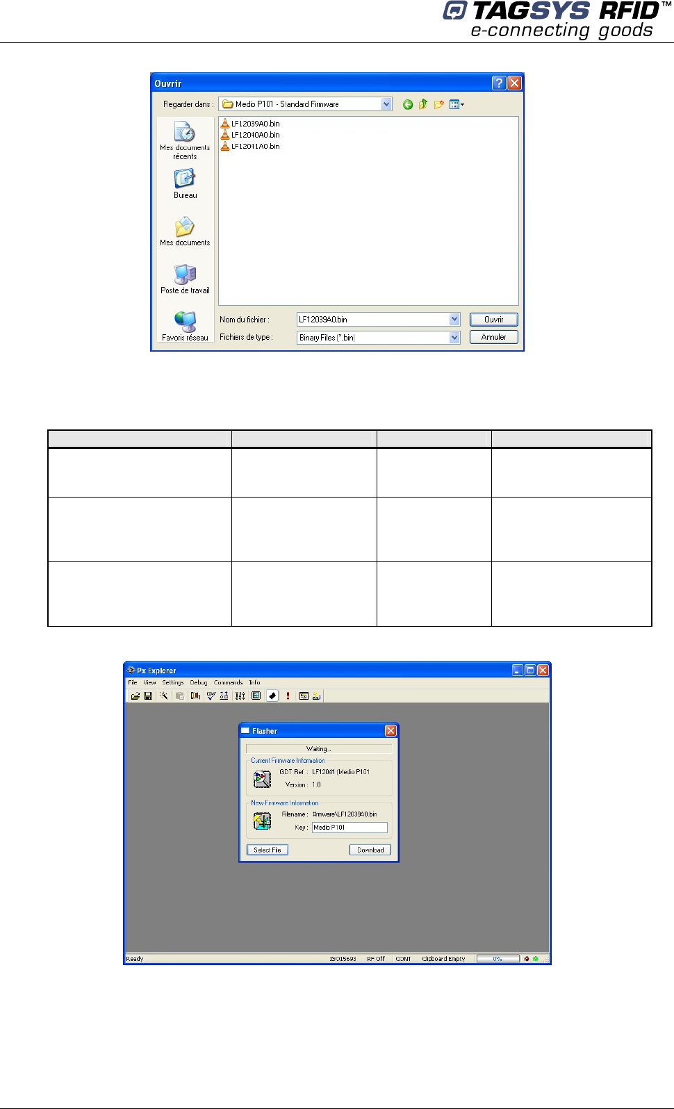
The flasher window pops up. Click on select file and go to the directory “\Medio P101 - Standard
Firmware” on the CDROM or to any other directory containing Medio P101 compatible firmware
(.bin files)
Medio P101-Ethernet
30/41 Revision 2.2 April 2008
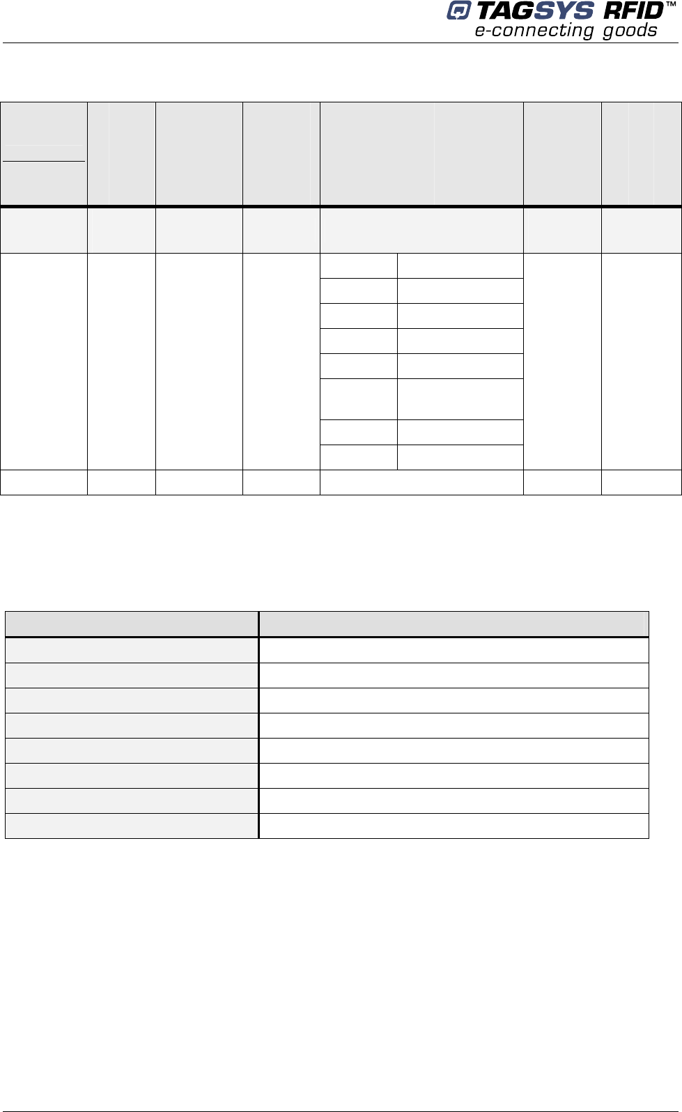
Select the firmware you want to download.
Standard firmwares are:
Firmware File Name Key Compatible chips
Library LF12039xx.bin Medio P101
C220
C320
C370 (ISO 15693)
Industry and Logistics
(I&L) LF12040xx.bin Medio P101
C270 (I-Code 1)
C370 (ISO 15693)
ePC
UID
Textile Rental LF12041xx.bin Medio P101
C210
C240
C270 (I-Code 1)
C370 (ISO 15693)
Verify the Key of the firmware to be able to download it. Key for standard firmware is “Medio P101”
(with a space character between Medio and P101). For non standard firmware, a key will be
supplied with.
Click on Download button and wait until the download is complete.

Stand-alone Mode
April 2008 Revision 2.2 31/41
6 Stand-alone Mode
Stand-alone Mode is designed to use the reader without using any command set. While in this
mode, the reader is limited to tag reading.
The reader sends the tag ID to the Host System using ASCII protocol via the Reader-to-Host
interface.
ASCII protocol is used in order to provide hexadecimal data that can be read by a variety of
terminal programs (e.g. Microsoft® HyperTerminal).
6.1 Stand-alone Mode Features
Table 3 lists the available Stand-alone mode features.
Table 3: Available Features in Stand-alone Mode
Features TR-P101
Customized tag type reading
compatibility
(depending on downloaded
application firmware)
C210
C240
C220
C270 (ICode1)
C320
C370 (ISO15693)
I-Code ePC/I-Code UID
Serial Communication Type USB 1.1
Ethernet (Raw TCP serial communication)
Repetition Option Available
Customized ASCII message format
STX/ETX Characters
Header String
Chip Description String
ID String (variable length)
End of Message String
Input Trigger Available
Output for active trigger information Available
Output for tag reading information Available
6.1.1 Customized ASCII Message Format
When a tag is read, its data are transmitted to the host in the form of an ASCII character frame.
Medio P101-Ethernet
32/41 Revision 2.2 April 2008
Table 4: Customized ASCII Message Format (TAGSYS RFID Tag is read)
Start of Text
Header
String
Chip
Description
String
ID
End of
Message
String
End of Text
Description <STX>
(0x02)
“TAGSYS-“
(Default) Chip name <CR/LF>
(Default)
<ETX>
(0x03)
C210 2 to 16 characters
C240 2 to 16 characters
C220 2 to 10 characters
C270 2 to 16 characters
C320 2 to 16 characters
C370 (ISO
15693) 2 to 16 characters
ePC 2 to 24 characters
Size
1
character
0 to 16
characters
0 to 16
characters
UID 2 to 10 characters
0 to 16
characters
1
character
TR-P101 Optional Optional Optional Required Optional Optional
Medio P101-Ethernet reader can decode all chips in Stand-alone mode. Only the ID field is
retrieved in the return ASCII message. All other fields are optional. The ID field length is
programmable; the default lengths are given in Table 5.
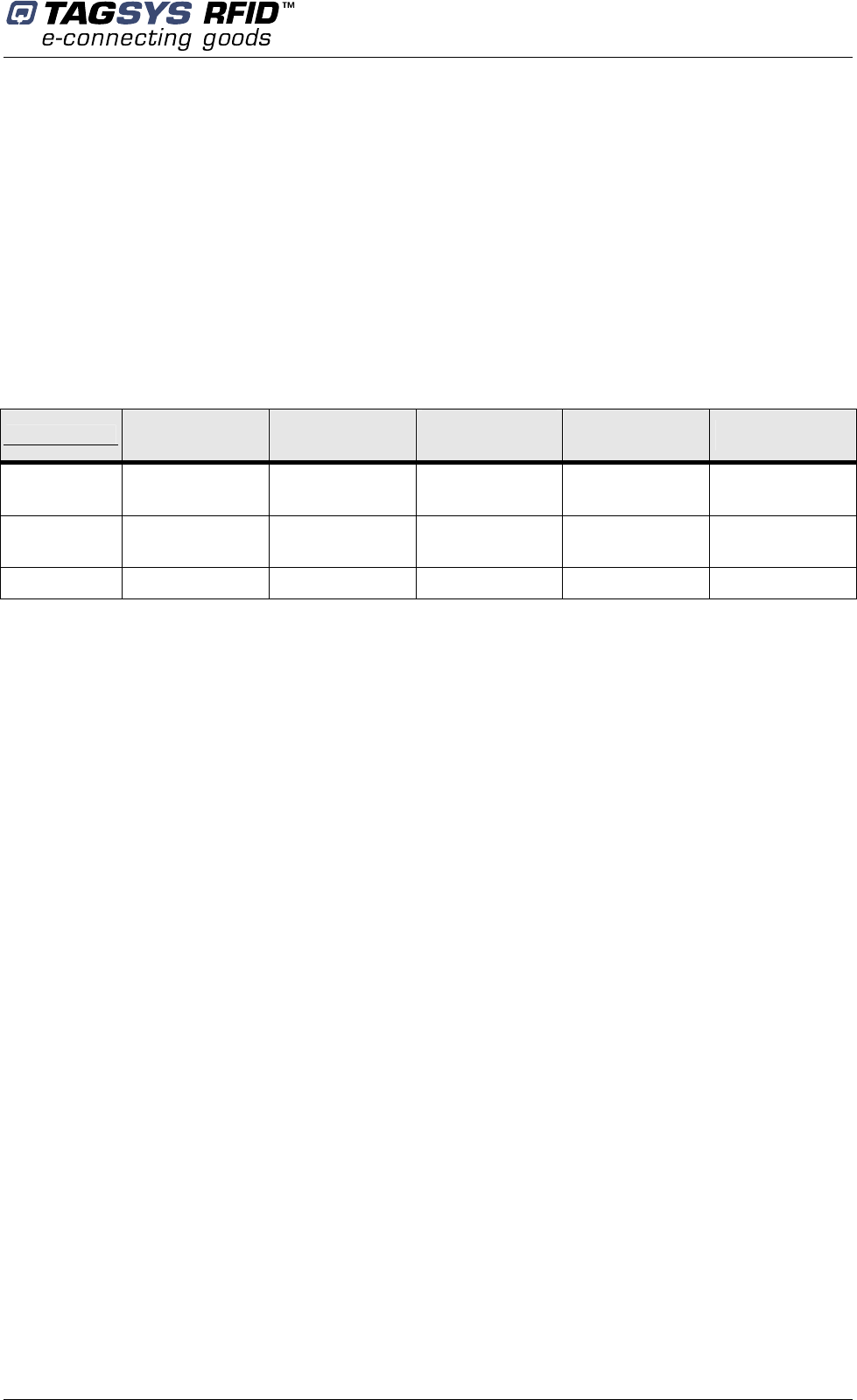
Table 5: Default ID Field Lengths
Chip Type Default ID Field Length
C210 chip 16 (Total memory)
C240 chip 16 (Block 0 Page 0)
C220 chip 10 (Lockable memory)
C270 chip 16 (Block 0 and Block 1)
C320 chip 16 (Block 0)
C370 chip (ISO 15693) 16 (UID)
ePC 24 (Block 0 to 11)
UID 10 (UID block 14 to 18)
6.1.2 Repetition Option
The reader constantly attempts to read any chips present in the field. When a chip ID is detected,
the reader can send the information to the host in one of 2 modes:
1. In “Repeated Read” mode, the reader returns a chip’s ID to the host with each successful
read operation.
2. In “Read Once” mode, the reader only returns the ID of a chip if the previous read
corresponds to a different chip, or if all reading attempts have failed 4 times (this feature
makes it possible to detect a chip’s potential exit out of the field).
Stand-alone Mode
April 2008 Revision 2.2 33/41
6.1.3 Trigger Input
When the trigger capability is enabled, a trigger state is used to start and stop the RF scanning.
The trigger is connected to the input of the reader.
Depending on the reply settings of the trigger, the ASCII message can be sent during the trigger
activity (Repeated Read mode and Read Once mode are available) or at the end of the trigger. In
this last case, a message is always sent to the host system:
if a tag has been read, the message contains its ID,
if a tag has not been read, the message contains a No Message string (that can be defined)
as shown in Table 6.
Table 6: Customized ASCII Message Format (TAGSYS RFID Tag is not read)
Start of Text Header String No Tag Found
String End of Message
String End of Text
Description <STX>
(0x02)
“TAGSYS-“
(Default)
“????????“
(Default)
<CR/LF>
(Default)
<ETX>
(0x03)
Size 1
character
0 to 16
characters
0 to 16
characters
0 to 16
characters
1
character
Status Optional Optional Required Optional Optional
6.1.4 Output Settings
The output of the reader can be used to monitor the trigger activity or the successful reads.
6.2 Stand-alone Mode Settings
Stand-alone Mode can be set in one of two ways while the reader is in Normal Operating mode
• By using the Px Explorer software provided with the reader
• By using “Set Stand-alone Mode” command followed by a “Reset Reader” command. For
more information, refer to the Medio P101-Ethernet Command Set document.
Medio P101-Ethernet
34/41 Revision 2.2 April 2008
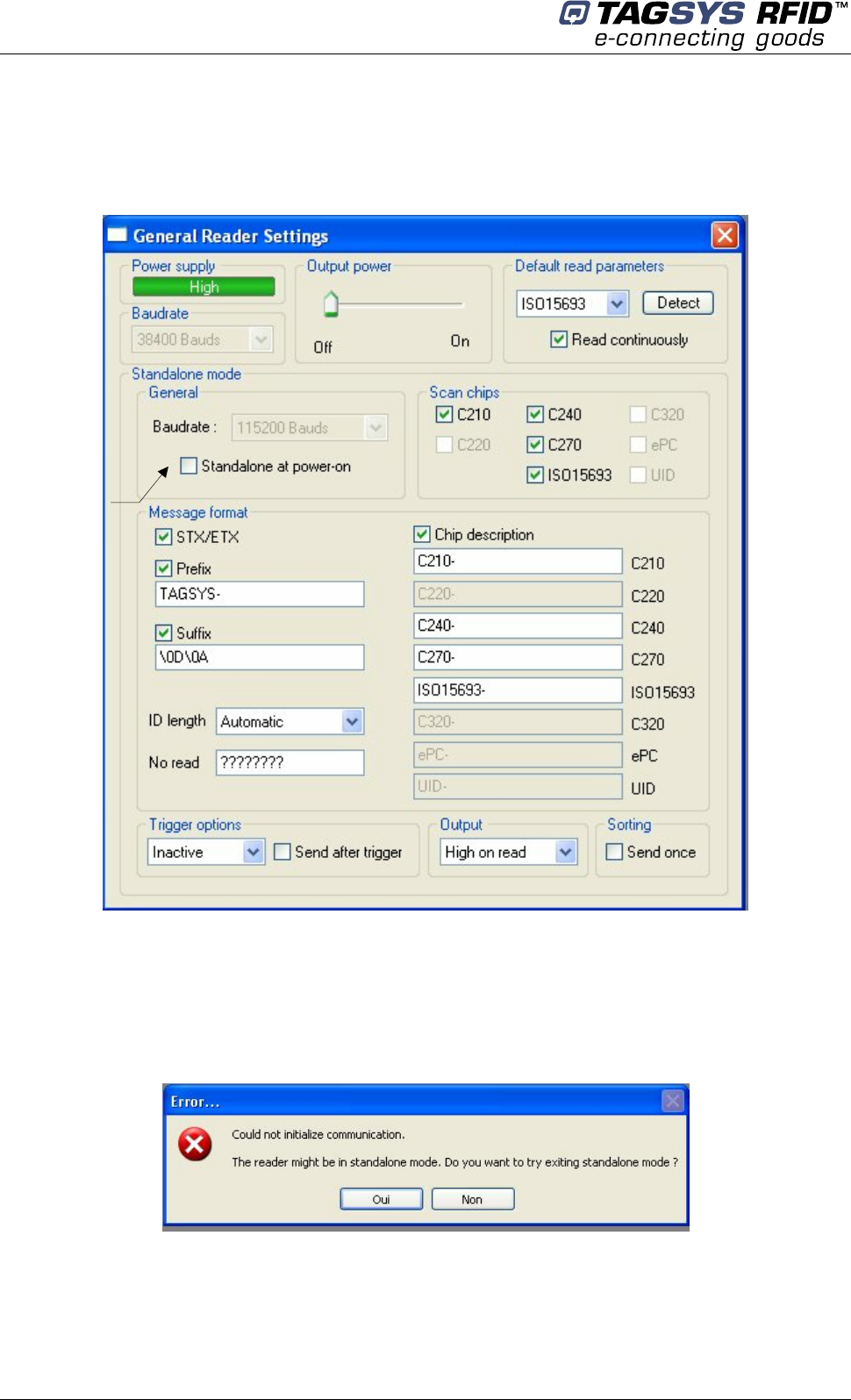
6.2.1 Using Px Explorer
Run the Px Explorer software. In the Settings menu, select General Reader Settings
6.3 Disabling Stand-alone Mode
The Medio P101-Ethernet can be reset in Standard mode in one of two ways as described below:
• Use the Px Explorer software provided with the reader and click Yes when the following
window is displayed
• Send the 'S' character using a console interface (for example, HyperTerminal).
Enable
Standalone
mode at next
power on

Connecting Peripheral Devices
April 2008 Revision 2.2 35/41
7 Connecting Peripheral Devices
7.1 Using the Universal Input pin
The reader input can be driven by a voltage source from 0V up to 25V referring to the input ground.
A relay (open chain transistor, switch…) can also be used to connect the input pin and its ground.
- Low level input voltage is defined to be in the range of 0 to 1.5V
- High level input voltage is defined to be in the range of 3 to 25V
7.2 Using the Universal Output pin
The output pin is an open drain power transistor that can drive a current up to 6A. When activated,
the power transistor connects the output pin and its ground.
The output transistor is protected against heating and current overload. If an overload happens, the
output stops driving current automatically. The output must be turned off to be re-activated.
7.2.1 Output Wiring
Example: Connecting a LED to the Output
+12V (Input voltage)
Pin 1
Pin 2
470 Ohms
The LED’s cathode is connected to the
Output pin and its anode to the Output Supply
Pin. Note that the Output supply selector is
configured to deliver 5V to supply the LED.
The internal serial resistor limits the current
delivered to the LED.
Medio P101-Ethernet
36/41 Revision 2.2 April 2008
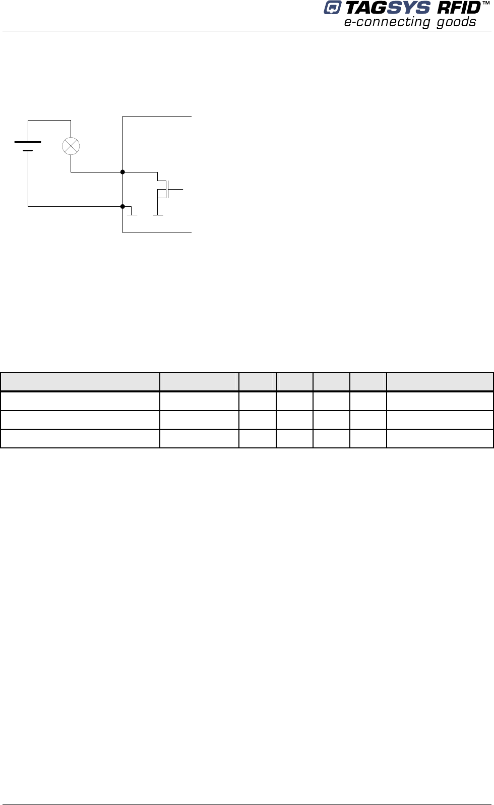
Example: Connecting a load using an external power
Pin 4
Pin 1
V
The external power must be less than 25V
7.3 I/O Electrical Signal Requirements
Table 7 provides the electrical DC characteristics.
Table 7: I/O Interface Pins - Electrical Characteristics
Parameters Conditions Min. Typ. Max. Unit Note
Input Voltage Low 0 2 V
Input Voltage High 3 25 V
Output Current 6 A

Technical Specifications
April 2008 Revision 2.2 37/41
8 Technical Specifications
Table 8: Medio P101-Ethernet Technical Specifications
Reference Medio L-P101
Size (L x W x H) 154 x 84 x 38 mm (TOPTEC 154F)
Weight 200 g
DC power 12 VDC +/- 10% Typical
Chip compatibility (depending on
downloaded firmware type)
C210
C240
C220 (Folio 20)
C320 (Folio 320)
ISO 15693 (Folio 370)
EPc
UID
Communication interface USB 1.1
Ethernet (Raw TCP)
RF Output Power 1.2 W Typical
Power consumption 4.5 W
Operating temperature 0° to +55°C
Storage temperature -20° to +70°C
Mechanical fixation Accessories for TOPTEC 154F boxes (Manufacturer : OKW)
Conformity ETSI 300-330 European Radio compliance
EN 50364
Communication protocol TAGSYS-specific STXE-2
Medio P101-Ethernet
38/41 Revision 2.2 April 2008
9 Electrical Characteristics
This chapter provides information about AC and DC characteristics for all pins. It also gives timing
characteristics for the different interfaces.
9.1 Absolute Maximum Ratings
Parameter Value
Ambient Operating Temperature 0°C to +55°C
Storage Temperature -20°C to +70°C
Supply Voltage with respect to GND 25 V
Total Power Dissipation 4.5 W
Total Power Dissipation on Antenna 1.2 W
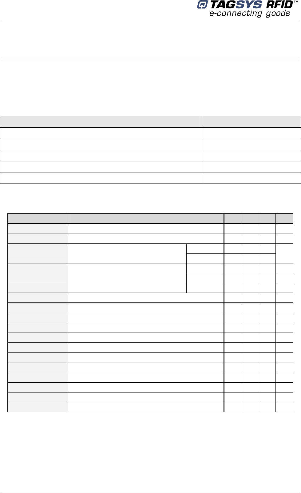
9.2 DC Characteristics
Value Description Max. Typ. Min. Unit
VSupply Supply Voltage 13.2 12 10.8 V
IRFOff Supply Current – RFOff – USB Plugged (VSupply = 12V) 50 45 40 mA
USB 268
IRFOn Supply Current ( RFOn, Dummy Load
50Ohm, VSupply = 12V) ETHERNET 339 mA
TR-HA1 339 mA
L-W1 351 mA
IRFOn
Supply Current
(RFOn, VSupply = 12V, Antenna connected,
Ethernet Communication) LSA-3 336 mA
TOp Operating Tempature 0 55 °C
VUSB Supply Voltage on USB cable 5.25 5 4.35 V
IUsb Supply Current on USB cable - 340 - µA
UVOH D+/D- Static Output high 3.6 2.8 V
UVOL D+/D- Static Output low 0.3 0 V
UVSE Single Ended Rx Threshold 2.0 0.8 V
UVCOM Differential Common Mode 2.5 0.8 V
UVDIF Differential Input sensitivity 0.2 V
ZDRV Driver Output impedance 44 29 Ohm
Input Voltage Low 2 0 V
Input Voltage High 25 3 V
Output Current 6 A

Warranty Conditions
April 2008 Revision 2.2 39/41
10 Warranty Conditions
10.1 Warranty
TAGSYS warrants that this Product shall comply with the functional specifications set forth herein
for a period of one year from the date of delivery to the Buyer.
This warranty is valid for the original Buyer of the Product and is not assignable or transferable to
any other party.
TAGSYS cannot be responsible in any way for, and disclaims any liability in connection with the
operation or performance of:
any product in which the Product is incorporated;
any equipment not supplied by TAGSYS which is attached to or used in connection with the
Product; or
the Product with any equipment
This warranty does only cover the Product to the exclusion of any such other equipment.
Optimal operation and performance of the Product are obtained by using TAGSYS’ readers, by
applying TAGSYS installation guidelines and by having your installation reviewed by a TAGSYS’
technical consultant.
TAGSYS warranty does not cover the installation, maintenance or service of the Product and is
strictly limited to the replacement of Products considered as defective by TAGSYS and returned
according to the return procedure defined below; in such case, TAGSYS will, at TAGSYS’ option,
either replace every defective Product by one new Product or refund the purchase price paid by
Buyer to TAGSYS for the defective Product.
10.2 Warranty Exclusions
Defects or damages resulting from storage of the Product under conditions which do not
comply with TAGSYS specifications or normal usage
Defects or damages resulting from use of the Product in abnormal conditions (abnormal
conditions being defined as any conditions exceeding the ones stated in the product
specifications).
Defects or damages from misuse, accident or neglect.
Defects from improper testing, operation, maintenance or installation.
Defects from alteration, modification except modifications or adjustments specifically described
in this Product reference guide, adjustment or repair, or any attempt to do any of the foregoing,
by anyone other than TAGSYS.
Any action on Product that prevents TAGSYS from performing an inspection and test of the
Product in case of a warranty claim.
Tampering with or abuse of the Product.
Any use or incorporation by the Buyer or a third party of TAGSYS' Product into life saving or life
support devices or systems, or any related products, TAGSYS expressly excludes any liability
for such use.

Medio P101-Ethernet
40/41 Revision 2.2 April 2008
10.2.1 General Provisions
This warranty sets forth the full extent of TAGSYS responsibility regarding the Product.
In any event, TAGSYS warranty is strictly limited to (at TAGSYS’ sole option) the replacement or
refund of the Products purchase price to TAGSYS, of Products considered as defective by
TAGSYS.
The remedy provided above is in lieu and to the exclusion of all other remedies, obligations or
liabilities on the part of TAGSYS for damages, whether in contract, tort or otherwise, and including
but not limited to, damages for any defects in the Products or for any injury, damage, or loss
resulting from such defects or from any work done in connection therewith or for consequential
loss, whether based upon lost goodwill, lost resale profits, impairment of other goods or arising
from claims by third parties or otherwise.
TAGSYS disclaims any explicit warranty not provided herein and any implied warranty, guaranty or
representation as to performance, quality and absence of hidden defects, and any remedy for
breach of contract, which but for this provision, might arise by implication, operation of law, custom
of trade or course of dealing, including implied warranties of merchantability and fitness for a
particular purpose.
10.2.2 How to Return Defective Products
The Buyer shall notify TAGSYS of the defects within 15 working days after the defects are
discovered.
Defective Products must be returned to TAGSYS after assignment by a TAGSYS Quality
Department representative of an RMA (Return Material Authorization) number. No Products shall
be returned without their proof of purchase and without the acceptance number relating to the
return procedure.
All Products shall be returned with a report from the Buyer stating the complete details of the
alleged defect.
Call +33 4 91 27 57 36 for return authorization and shipping address.
If returned Products prove to be non-defective, a charge will be applied to cover TAGSYS’ analysis
cost and shipping costs.
If the warranty does not apply for returned Products (due to age, or application of a warranty
exclusion clause), a quote for replacement will be issued, and no replacement will be granted until
a valid purchase order is received. If no purchase order is received within 30 days after the date of
TAGSYS quote, TAGSYS will return the products and charge the analysis cost and shipping costs.
All replaced Products shall become the property of TAGSYS.
The Product Return Form is included on the following page. This form should accompany any
product you need to return to TAGSYS for analysis in the event of a problem.
Warranty Conditions
April 2008 Revision 2.2 41/41
Product Return Form
Customer Profile:
Company: ................................................................
Address: ..................................................................
.................................................................................
.................................................................................
City & State:.............................................................
Zip Code: .................................................................
Country: ...................................................................
Contact Name: .......................................................
Contact e-mail: ......................................................
Contact Phone: ......................................................
Contact Fax:...........................................................
Order identification:
Product Name:.........................................................
Order Number (OEF):..............................................
Invoice Number: .....................................................
Return Quantity: ....................................................
Reason for return:
.........................................................................................................................................................................
.........................................................................................................................................................................
.........................................................................................................................................................................
.........................................................................................................................................................................
.........................................................................................................................................................................
To inform TAGSYS of this return, please email it to
RMA@tagsysrfid.com
Address to ship the product with this document attached:
TAGSYS
QUALITY DEPARTMENT
180, chemin de Saint Lambert
13821 La Penne sur Huveaune France
To inform TAGSYS of this return, please also fax it to your Customer Service Representative
+33 491-275-701
Return Procedure:
The product returned will go through stringent quality controls.
A final analysis report will be sent to you as soon as possible.
Please contact your Quality Service representative for further details.
+33 491-275-736
This product bears the selective sorting symbol for waste electrical and electronic equipment
(WEEE)
This means that this product must be handled pursuant to European Directive 2002/96/EC in
order to be recycled or dismantled to minimize its impact on the environment.
For further information, please contact your local or regional authorities.