Tait TBA8C0 Base Station Transceiver User Manual TB8100 instal oper man
Tait Limited Base Station Transceiver TB8100 instal oper man
UserManual.wiki
>
Tait
>
TBA8C0 User Manual
Exhibit D Users Manual per 2 1033 c3
Navigation menu
Upload a User Manual
Namespaces
Wiki Guide
HTML
PDF
Info
Views
User Manual
Discussion / Help
Navigation
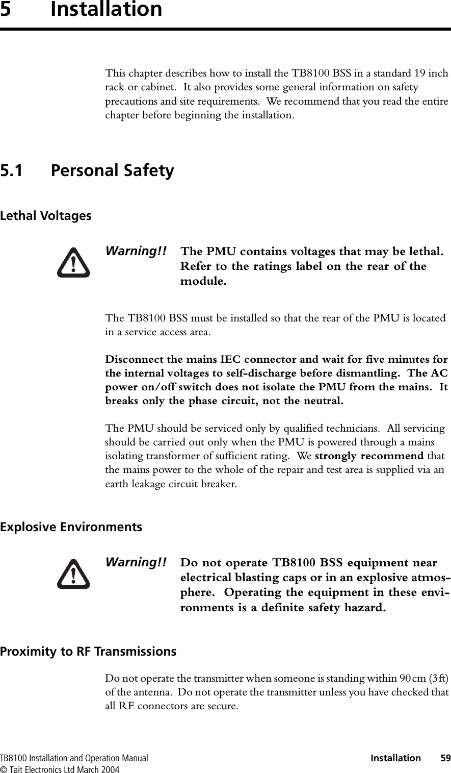
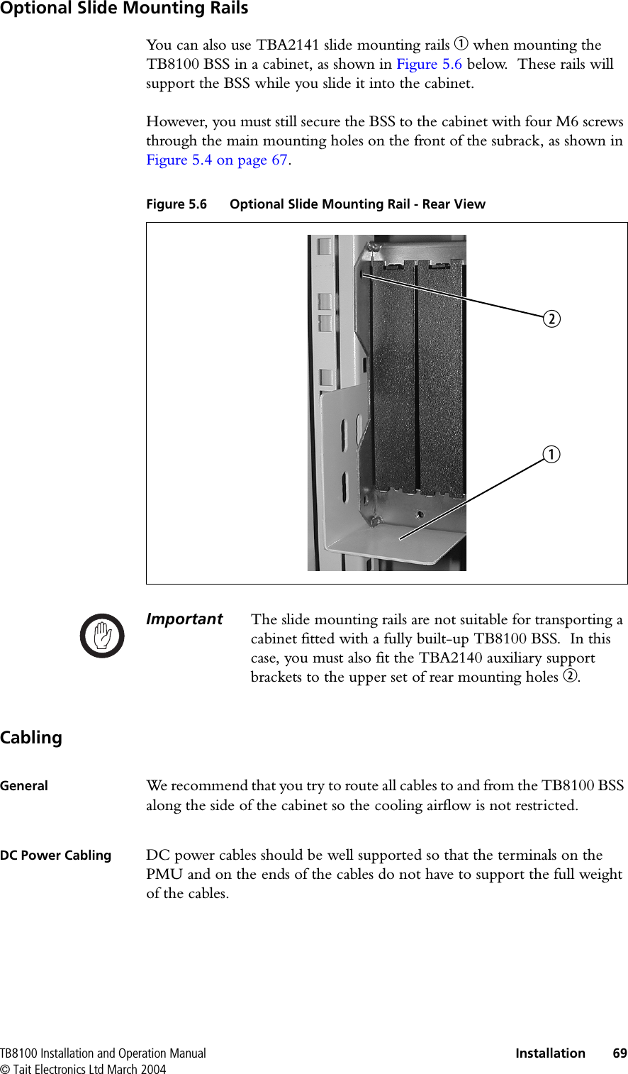
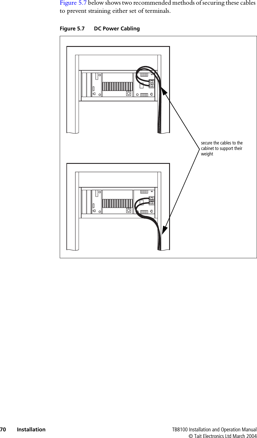
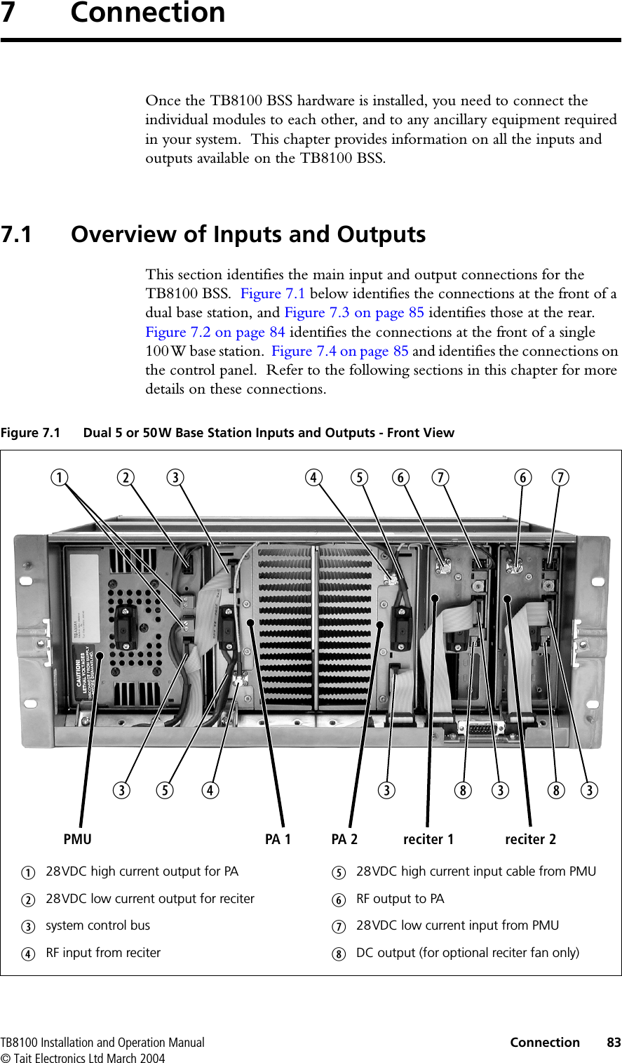
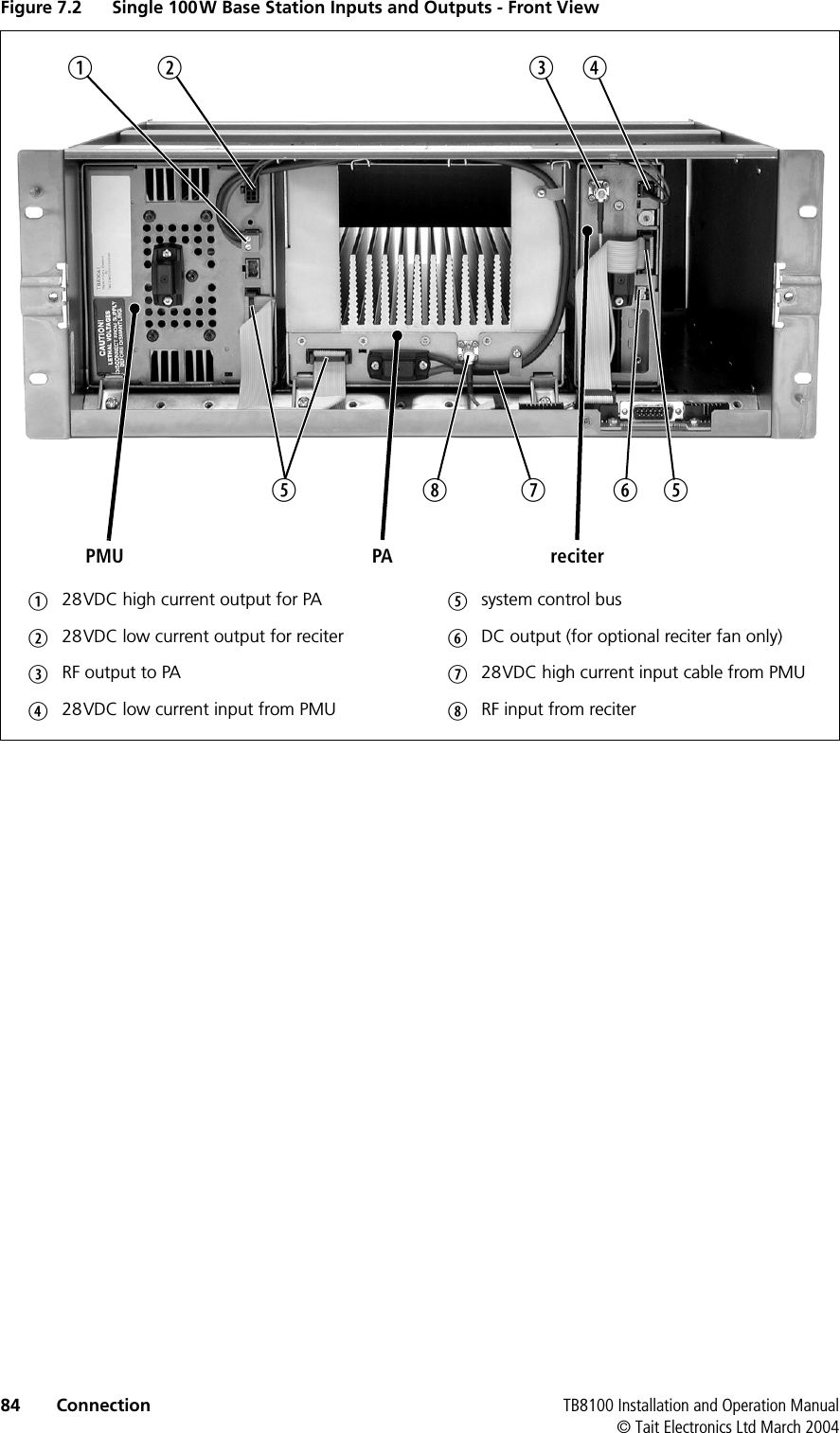
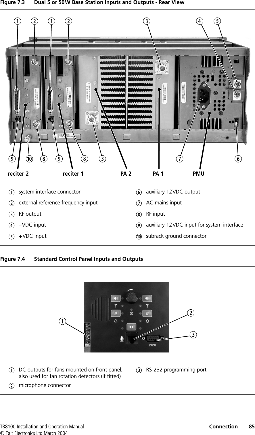
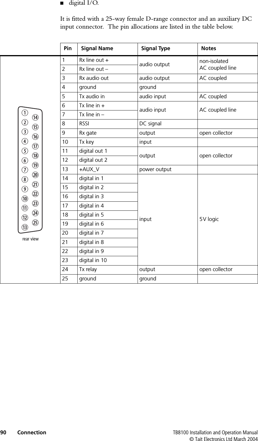
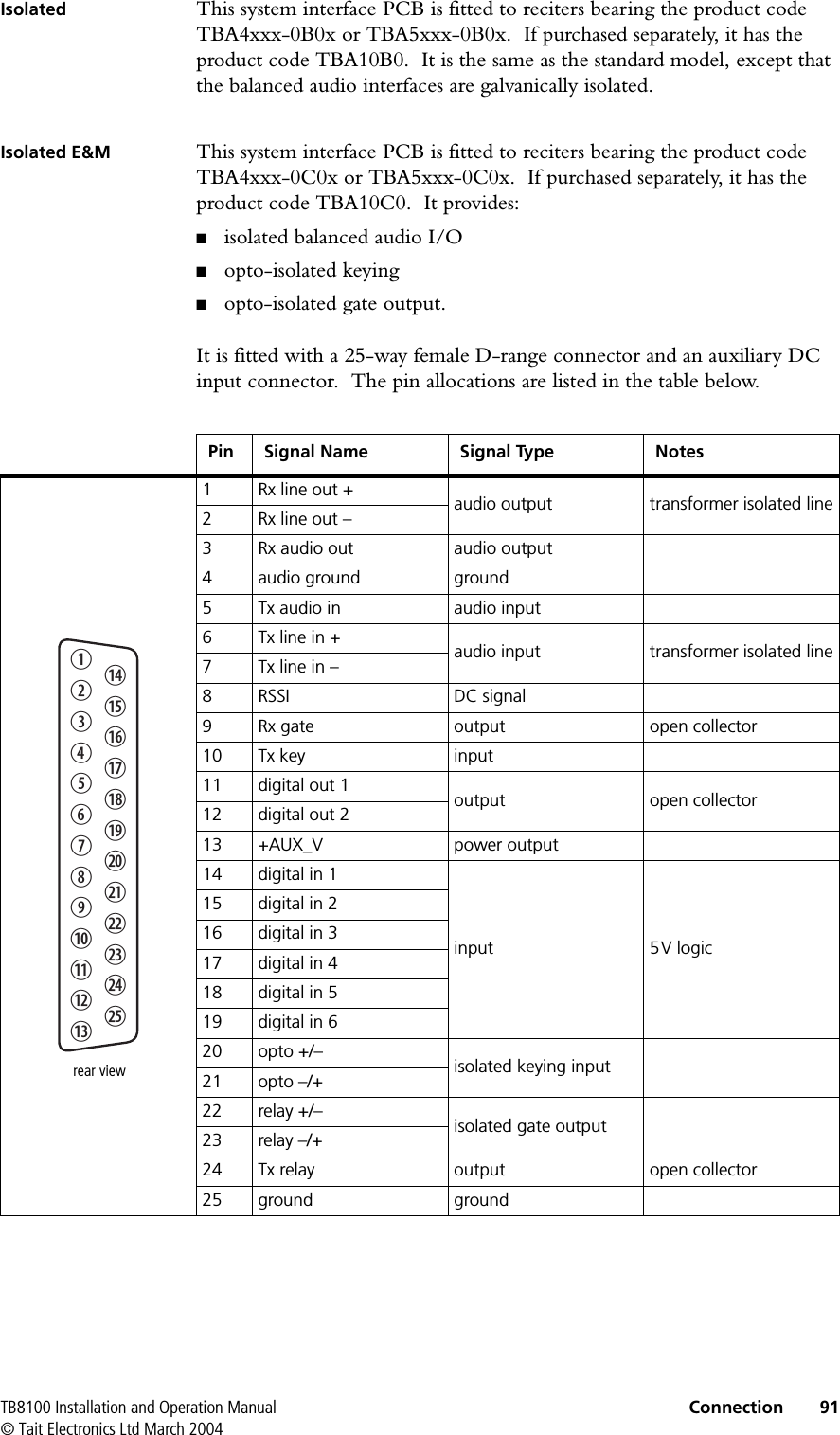
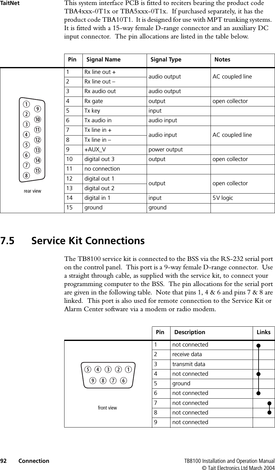
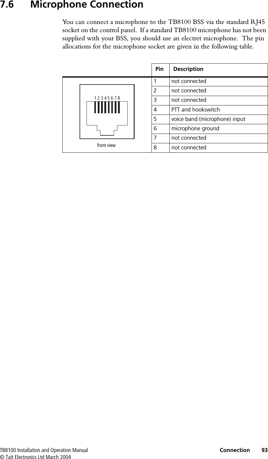
![60 Installation TB8100 Installation and Operation Manual© Tait Electronics Ltd March 2004High TemperaturesTake care when handling a PMU or PA which has been operating recently. Under extreme operating conditions (+60°C [+140°F] ambient air temperature) or high duty cycles the external surfaces of the PMU and PA can reach temperatures of up to +80°C (+176°F).5.2 Equipment SafetyESD PrecautionsImportant This equipment contains devices which are susceptible to damage from static charges. You must handle these devices carefully and according to the procedures described in the manufacturers’ data books.We recommend you purchase an antistatic bench kit from a reputable manufacturer and install and test it according to the manufacturer’s instructions. Figure 5.1 shows a typical antistatic bench set-up.You can obtain further information on antistatic precautions and the dangers of electrostatic discharge (ESD) from standards such as ANSI/ESD S20.20-1999 or BS EN 100015-4 1994. Aerial LoadThe TB8100 BSS equipment has been designed to operate safely under a wide range of aerial loading conditions. However, we strongly recommend that the transmitter should always be operated with a suitable load to prevent damage to the transmitter output power stage.Figure 5.1 Typical Antistatic Bench Set-upcommon point ground (building ground or mains ground via 1M ohm series resistor)conductive wrist strap dissipative rubber bench mat](https://usermanual.wiki/Tait/TBA8C0/User-Guide-713510-Page-2.png)