Tait TBA9K2 Base Station Transceiver User Manual TB8100 Installation and Operation Manual
Tait Limited Base Station Transceiver TB8100 Installation and Operation Manual
Tait >
Exhibit D Users Manual per 2 1033 c3
TB8100 Installation and Operation Manual Connection 55
© Tait Electronics Ltd June 2003
6 Connection
Once the TB8100 BSS hardware is installed, you need to connect the
individual modules to each other, and to any ancillary equipment required
in your system. This chapter provides information on all the inputs and
outputs available on the TB8100 BSS.
6.1 Overview of Inputs and Outputs
This section identifies the main input and output connections for the
TB8100 BSS. Figure 6.1 below identifies the connections at the front of a
dual base station, and Figure 6.3 on page 57 identifies those at the rear.
Figure 6.2 on page 56 identifies the connections at the front of a single
100W base station. Figure 6.4 on page 57 identifies the connections on the
control panel. Refer to the following sections in this chapter for more
details on these connections.
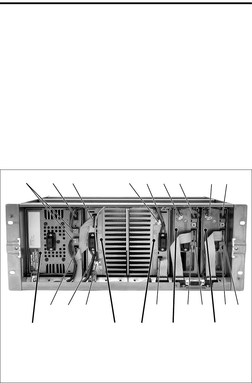
Figure 6.1 Dual 5 or 50W Base Station Inputs and Outputs - Front View
b28VDC high current output for PA f28VDC high current input cable from PMU
c28VDC low current output for reciter gRF output to PA
dsystem control bus h28VDC low current input from PMU
eRF input from reciter iDC output (for optional reciter fan only)
bcd e ghfgh
ddidiefd
PA 1 PA 2 reciter 2PMU reciter 1
56 Connection TB8100 Installation and Operation Manual
© Tait Electronics Ltd June 2003
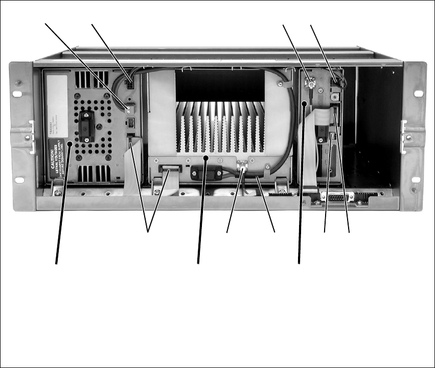
Figure 6.2 Single 100W Base Station Inputs and Outputs - Front View
b28VDC high current output for PA fsystem control bus
c28VDC low current output for reciter gDC output (for optional reciter fan only)
dRF output to PA h28VDC high current input cable from PMU
e28VDC low current input from PMU iRF input from reciter
bc de
hfgfi
PA reciter
PMU
TB8100 Installation and Operation Manual Connection 57
© Tait Electronics Ltd June 2003
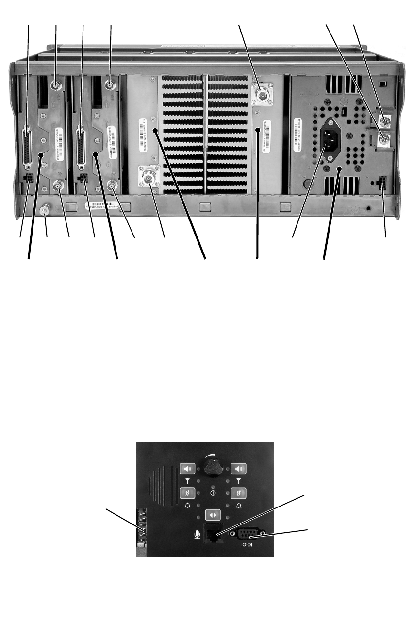
Figure 6.3 Dual 5 or 50W Base Station Inputs and Outputs - Rear View
bsystem interface connector gauxiliary 12VDC output
cexternal reference frequency input hAC mains input
dRF output iRF input
e–VDC input jauxiliary 12VDC input for system interface
f+VDC input 1) subrack ground connector
bc d fe
higidjj
PA 1PA 2reciter 1reciter 2 PMU
bc
1)
Figure 6.4 Control Panel Inputs and Outputs
bDC outputs for fans mounted on front panel;
also used for fan rotation detectors (if fitted)
dRS-232 programming port
cmicrophone connector
b
c
d
58 Connection TB8100 Installation and Operation Manual
© Tait Electronics Ltd June 2003
6.2 Power Supply Connections
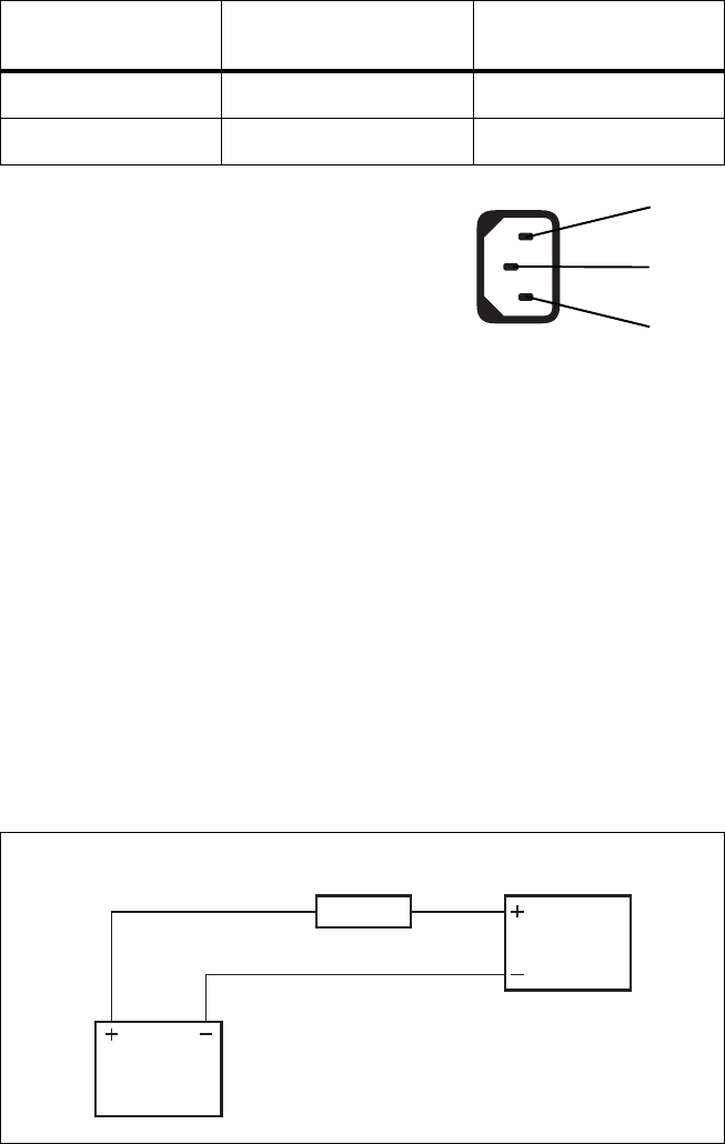
AC Power The TB8100 PMU is designed to accept a mains input of 88 to 264VAC at
45 to 65Hz. We recommend that a standard 3-wire grounded outlet is used
to supply the AC power. The socket-outlet must be installed near the
equipment and must be easily accessible. This outlet should be connected
to an AC power supply capable of providing a maximum of 600W. The
requirements of two typical AC supplies are given in the following table.
Your TB8100 BSS should come supplied
with a power supply cord to connect the
male IEC connector on the PMU to the
local AC supply. The pins of the IEC
connector on the PMU are identified at
right.
DC Power The TB8100 PMU is designed to accept a DC input of 10.3 to 15.5VDC
with negative or positive ground. There is a minimum DC start-up
threshold to prevent damaging a battery which has little capacity left.
You must connect the DC supply from the battery to the PMU via a fuse or
DC-rated circuit breaker with a rating of 60A. The DC input leads should
be of a suitable gauge to ensure less than 0.2V drop at maximum load over
the required length of lead.
Terminate and insulate the DC input leads so they are protected from
accidentally shorting to the subrack if the PMU is removed before the leads
are disconnected.
Nominal Supply Current Requirement Circuit Breaker/Fuse
Rating
115VAC 8A 10A
230VAC 4A 6A
phase
neutral
ground
rear view
Figure 6.5 Recommended DC Power Connection
Battery
PMU
Circuit Breaker
or Fuse
TB8100 Installation and Operation Manual Connection 59
© Tait Electronics Ltd June 2003
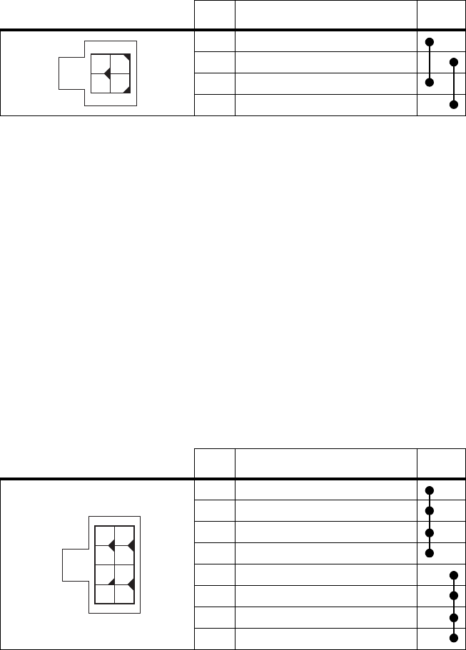
Reciter Auxiliary DC
Input The system interface PCB in the reciter has an auxiliary DC input
connector. DC from the auxiliary DC output on the PMU (see “PMU
Auxiliary DC Output” below) can be supplied to the +AUX_V pin on the
system interface connector via this input.
The pin allocations for the auxiliary DC input on the system interface PCB
are given in the following table. Note that pins 1 & 3 and pins 2 & 4 on this
connector are linked. Refer to “System Connections” on page 60 for the
pin allocations for +AUX_V on each system interface PCB.
The DC output from the PMU is 12VDC. Although this power output is
isolated, the negative side of the supply is grounded on the system interface
PCB to give a +V output.
PMU Auxiliary DC
Output The PMU can provide an auxiliary DC output when it is fitted with the
optional 40W auxiliary power supply PCB. This power supply is current
limited to 3A and is available on the auxiliary DC output connector on the
rear panel. DC from this output can be supplied to the +AUX_V pin on
the system interface connector on the reciter via the auxiliary DC input
connector on the system interface PCB (see “Reciter Auxiliary DC Input”
above).
The pin allocations for the auxiliary DC output on the PMU are given in
the following table. Note that pins 1 to 4 and pins 5 to 8 on this connector
are linked.
Pin Description Links
1+V input
2 ground
3+V input
4 ground
1
2
3
4
rear view
Pin Description Links
1 +V output
2 +V output
3 +V output
4 +V output
5 ground
6 ground
7 ground
8 ground
1
5
26
37
48
rear view
60 Connection TB8100 Installation and Operation Manual
© Tait Electronics Ltd June 2003
6.3 RF Connections
The RF input to the TB8100 BSS is via the lower BNC connector on the
rear panel of the reciter. The RF output is via the N-type connector on the
rear panel of the PA (refer to Figure 6.3 on page 57).
We recommend that you use dual-screened coaxial cable such as RG223 for
the BNC connections, and RG214 for the N-type connections.
6.4 System Connections
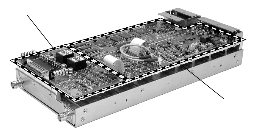
The reciter can be fitted with an optional system interface PCB which
provides the links between the reciter’s internal circuitry and external
equipment. This PCB is securely mounted to the reciter’s chassis and is
connected to the control PCB with a flexible connector. The system
interface PCB is fitted with industry-standard connectors and several
standard types are available for different applications.
The circuitry on the system interface PCB provides additional signal
processing so that the outputs meet standard system requirements. It also
enables the PCB to identify itself to the reciter control circuitry.
The system interface PCB is removable, which makes it possible to change
the application of a reciter by removing one type of PCB and fitting another.
Only one system interface PCB can be fitted to a reciter at any one time.
This section provides details on the system interface PCBs available at the
time of publication. Other types may be developed for future applications.
Figure 6.6 System Interface PCB
system interface PCB*
control PCB
*standard system interface PCB shown
TB8100 Installation and Operation Manual Connection 61
© Tait Electronics Ltd June 2003
Standard The standard system interface PCB is fitted to reciters bearing the product
code TBA4xxx-0A0x or TBA5xxx-0A0x. If purchased separately, it has the
product code TBA10A0. It provides:
■non-isolated 600Ω balanced audio I/O
■high impedance unbalanced audio I/O
■Tx key
■Rx gate
■RSSI
■Tx relay
■digital I/O.
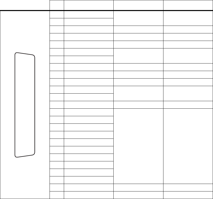
It is fitted with a 25-way female D-range connector and an auxiliary DC
input connector. The pin allocations are listed in the table below.
Pin Signal Name Signal Type Notes
1 Rx line out + audio output non-isolated
AC coupled line
2 Rx line out –
3 Rx audio out audio output AC coupled
4 ground ground
5 Tx audio in audio input AC coupled
6 Tx line in + audio input AC coupled line
7 Tx line in –
8 RSSI DC signal
9 Rx gate output open collector
10 Tx key input
11 digital out 1 output open collector
12 digital out 2
13 +AUX_V power output
14 digital in 1
input 5V logic
15 digital in 2
16 digital in 3
17 digital in 4
18 digital in 5
19 digital in 6
20 digital in 7
21 digital in 8
22 digital in 9
23 digital in 10
24 Tx relay output open collector
25 ground ground
B
C
D
E
F
G
H
I
J
1)
1!
1@
1#
1$
1%
1^
1&
1*
1(
2)
2!
2@
2#
2$
2%
rear view
62 Connection TB8100 Installation and Operation Manual
© Tait Electronics Ltd June 2003
Isolated This system interface PCB is fitted to reciters bearing the product code
TBA4xxx-0B0x or TBA5xxx-0B0x. If purchased separately, it has the
product code TBA10B0. It is the same as the standard model, except that
the balanced audio interfaces are galvanically isolated.
Isolated E&M This system interface PCB is fitted to reciters bearing the product code
TBA4xxx-0C0x or TBA5xxx-0C0x. If purchased separately, it has the
product code TBA10C0. It provides:
■isolated balanced audio I/O
■opto-isolated keying
■opto-isolated gate output.
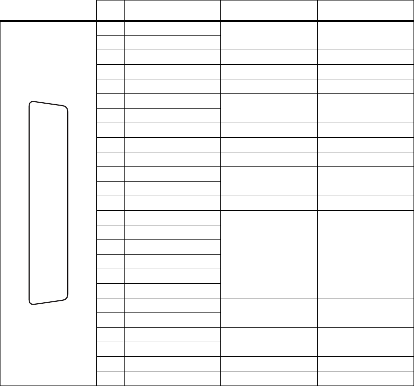
It is fitted with a 25-way female D-range connector and an auxiliary DC
input connector. The pin allocations are listed in the table below.
Pin Signal Name Signal Type Notes
1 Rx line out + audio output transformer isolated line
2 Rx line out –
3 Rx audio out audio output
4 audio ground ground
5 Tx audio in audio input
6 Tx line in + audio input transformer isolated line
7 Tx line in –
8 RSSI DC signal
9 Rx gate output open collector
10 Tx key input
11 digital out 1 output open collector
12 digital out 2
13 +AUX_V power output
14 digital in 1
input 5V logic
15 digital in 2
16 digital in 3
17 digital in 4
18 digital in 5
19 digital in 6
20 opto +/– isolated keying input
21 opto –/+
22 relay +/– isolated gate output
23 relay –/+
24 Tx relay output open collector
25 ground ground
B
C
D
E
F
G
H
I
J
1)
1!
1@
1#
1$
1%
1^
1&
1*
1(
2)
2!
2@
2#
2$
2%
rear view
TB8100 Installation and Operation Manual Connection 63
© Tait Electronics Ltd June 2003
Ta it N e t This system interface PCB is fitted to reciters bearing the product code
TBA4xxx-0T1x or TBA5xxx-0T1x. If purchased separately, it has the
product code TBA10T1. It is designed for use with MPT trunking systems.
It is fitted with a 15-way female D-range connector and an auxiliary DC
input connector. The pin allocations are listed in the table below.
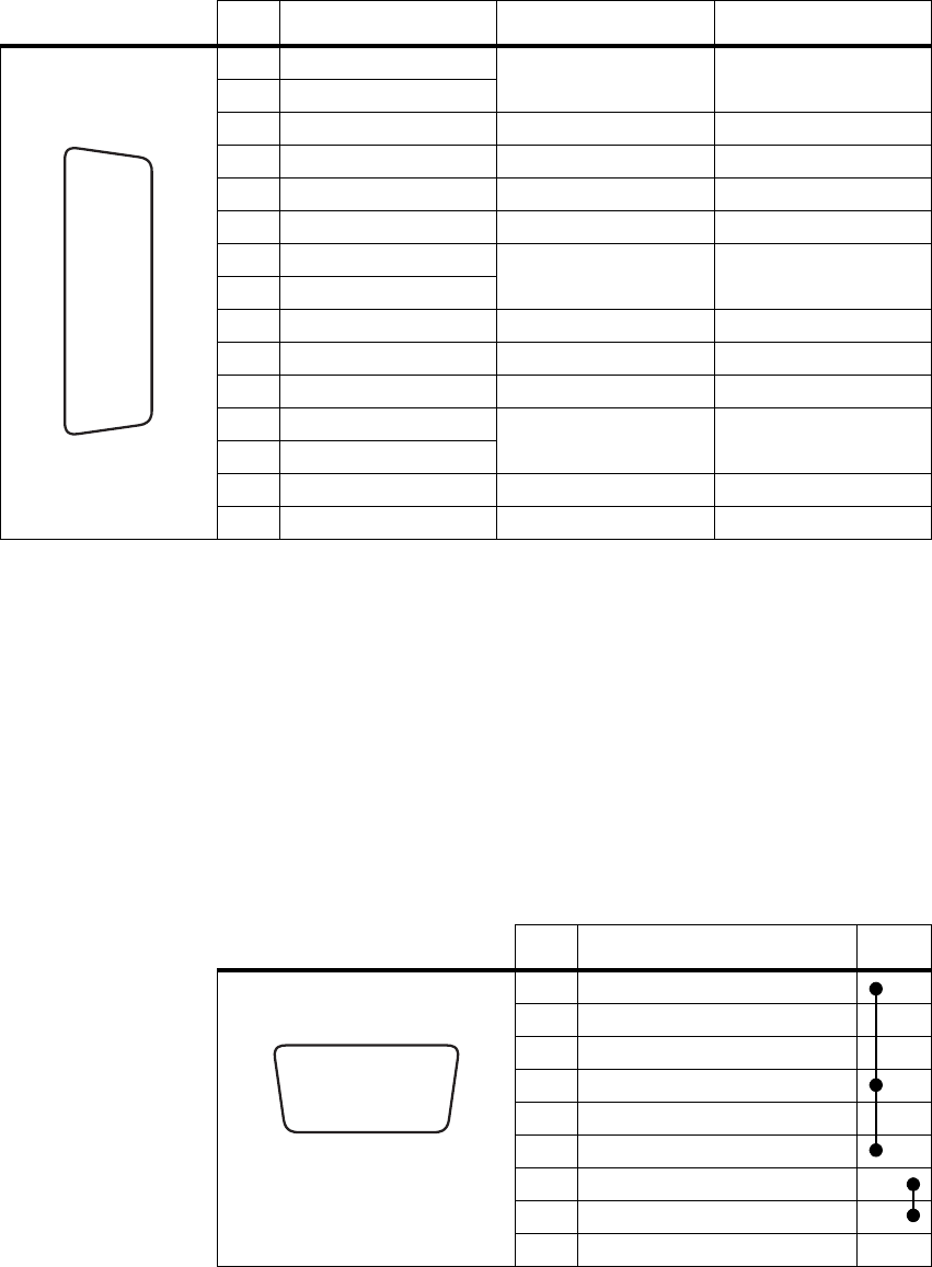
6.5 Service Kit Connections
The TB8100 service kit is connected to the BSS via the RS-232 serial port
on the control panel. This port is a 9-way female D-range connector. Use
a straight through cable, as supplied with the service kit, to connect your
programming computer to the BSS. The pin allocations for the serial port
are given in the following table. Note that pins 1, 4 & 6 and pins 7 & 8 are
linked. This port is also used for remote connection to the Service Kit or
Alarm Center software via a modem or radio modem.
Pin Signal Name Signal Type Notes
1 Rx line out + audio output AC coupled line
2 Rx line out –
3 Rx audio out audio output
4 Rx gate output open collector
5 Tx key input
6 Tx audio in audio input
7 Tx line in + audio input AC coupled line
8 Tx line in –
9 +AUX_V power output
10 digital out 3 output open collector
11 no connection
12 digital out 1 output open collector
13 digital out 2
14 digital in 1 input 5V logic
15 ground ground
J
B
C
D
E
F
G
H
I
1)
1!
1@
1#
1$
1%
rear view
Pin Description Links
1 not connected
2receive data
3 transmit data
4 not connected
5 ground
6 not connected
7 not connected
8 not connected
9 not connected
hj
b
gi
cdef
front view

64 Connection TB8100 Installation and Operation Manual
© Tait Electronics Ltd June 2003
6.6 Microphone Connection
You can connect a microphone to the TB8100 BSS via the standard RJ45
socket on the control panel. If a standard TB8100 microphone has not been
supplied with your BSS, you should use an electret microphone. The pin
allocations for the microphone socket are given in the following table.
Pin Description
1 not connected
2 not connected
3 not connected
4 PTT and hookswitch
5 voice band (microphone) input
6 microphone ground
7 not connected
8 not connected
12345678
front view