Tait TBAL0 Base Station Transceiver User Manual TB8100 Calibration Kit User s Manual
Tait Limited Base Station Transceiver TB8100 Calibration Kit User s Manual
Tait >
Exhibit D Users Manual per 2 1033 c3

Calibration Kit
User’s Manual
MBA-00011-05
March 2005
TB8100 base station

TB8100 Calibration Kit User’s Manual Contents i
Contents
Preface ..............................................................................................................iii
Enquiries and Comments ..................................................................iii
Updates of Manual and Equipment ...................................................iii
Copyright .........................................................................................iii
Disclaimer ........................................................................................iii
Typographical Conventions ..............................................................iii
Associated Documentation ...............................................................iii
Publication Record ..........................................................................iv
Basic Tasks .........................................................................................................1
Using the TB8100 Calibration Kit ..........................................................1
About the Toolbar ............................................................................2
About the Status Bar ..........................................................................2
Equipment Required ..............................................................................3
Calibration Overview .............................................................................3
Field Calibration ................................................................................4
Service Center Calibration .................................................................4
Selecting the Communications Port ........................................................5
Connecting to a Reciter Outside the Subrack .........................................5
Connecting to a Reciter via the Control Panel .......................................7
Disconnecting from the Base Station/Reciter .........................................7
Troubleshooting .....................................................................................8
Adjusting the Frequency Setup ........................................................................9
Adjusting the Receiver Lock Band .........................................................9
Tuning the Receiver Front End ...........................................................10
Tuning a K-Band, H-Band, or L-Band Receiver Front End ............11
Tuning a VHF Receiver Front End .................................................12
Adjusting the Exciter Lock Band ..........................................................13
Calibrating the Reciter ....................................................................................14
Calibrating the Exciter ..........................................................................14
Automatically Tune the Frequency Control Loop (FCL) .................14
Calibrating the FCL .........................................................................14
Calibrating the VCO .......................................................................16
Calibrating the RSSI .............................................................................17
Audio Calibration .................................................................................18
Calibrating the Balanced Lines .........................................................18
Calibrating the Unbalanced Lines ....................................................19
Carrier Frequency Offset Adjustment
(Older Reciters) ....................................................................................21
Carrier Frequency Offset Adjustment
(Newer Reciters) ..................................................................................22
Calibrating the Power Amplifier ....................................................................24

ii Contents © Tait Electronics Limited 2005
Calibrating the PA Bias ........................................................................ 24
Calibrating the Forward and Reverse Detector Bias Voltages ............... 25
Calibrating the PA Power .................................................................... 25
Troubleshooting Tips ..................................................................... 26
Calibrating the Supply Voltage ............................................................. 27
Calibrating the Power Management Unit .................................................... 28
Calibrating the PMU Output Voltage .................................................. 28
Index .................................................................................. 29

TB8100 Calibration Kit User’s Manual Preface iii
Preface
Welcome to the TB8100 Calibration Kit User’s Manual. This manual provides
you with information about the Tait TB8100 Calibration Kit in PDF format.
You can view it online or print it if you want a paper copy. It describes how to
use Version 02.05 of the Calibration Kit.
Enquiries and Comments
Any enquiries regarding this manual as well as any comments, suggestions and
notifications of errors should be sent to support@taitworld.com, or addressed
to the Support Group Manager, Tait Electronics Limited, PO Box 1645
Christchurch, New Zealand.
Updates of Manual and Equipment
In the interests of improving the performance, reliability or servicing of the
equipment, Tait Electronics Limited reserves the right to update the equipment
or this manual or both without prior notice.
Copyright
All information contained in this manual is the property of Tait Electronics
Limited. All rights are reserved. This manual may not, in whole or in part, be
copied, photocopied, reproduced, translated, stored, or reduced to any
electronic medium or machine-readable form, without prior written
permission from Tait Electronics Limited. All trade names referenced are the
service mark, trademark or registered trademark of the respective
manufacturers.
Disclaimer
There are no warranties extended or granted by this manual. Tait Electronics
Limited accepts no responsibility for damage arising from use of the information
contained in the manual or of the equipment and software it describes. It is the
responsibility of the user to ensure that use of such information, equipment and
software complies with the laws, rules and regulations of the applicable
jurisdictions.
Typographical Conventions
‘File > Exit’ means ‘click File on the menu bar, then select Exit’.
Associated Documentation
■Online Help. The Calibration Kit also has online Help. It contains more or
less the same information as this manual. To view it, start the Calibration
Kit, then press F1 or click the Help icon on the toolbar. If you are in a dialog
box, click the Help button.
■TB8100 Installation and Operation Manual.
■TB8100 Service Manual (service centers only). A glossary of terms is available
in this manual.
■TN-778 The TB8100 Calibration and Test Unit.
For additional items, see the TB8100 Installation and Operation Manual and
the TB8100 Service Kit User’s Manual or online Help.

iv Preface © Tait Electronics Limited 2005
Publication Record
Version Date Description
1.0 June 2003 First release of the manual for Version 1.0.0
of the Tait TB8100 Calibration Kit software.
02.00 March 2004 Minor quality issues resolved and software
changes documented for Version 02.00.
02.01
(MBA-00011-03)
September
2004
Carrier Frequency Offset Adjustment
procedure for reciter version 00.03+ added.
PA store supply voltage and PMU output
voltage calibration added.
02.02
(MBA-00011-04)
December
2004
Changes for K-band reciters.
02.05
(MBA-00011-05)
March
2005
Minor changes for Calibration Kit software
version 02.05. L-band reciters.
TB8100 Calibration Kit User’s Manual Using the TB8100 Calibration Kit 1
Basic Tasks
The TB8100 Calibration Kit is a Windows-based software program that allows
you to adjust the switching ranges of Tait TB8100 base stations (both receiver
and transmitter), and to flatten the receiver response across that switching range.
The TB8100 Calibration Kit is also used to calibrate the reciter, the PA, and
the PMU after servicing.
Using the TB8100 Calibration Kit
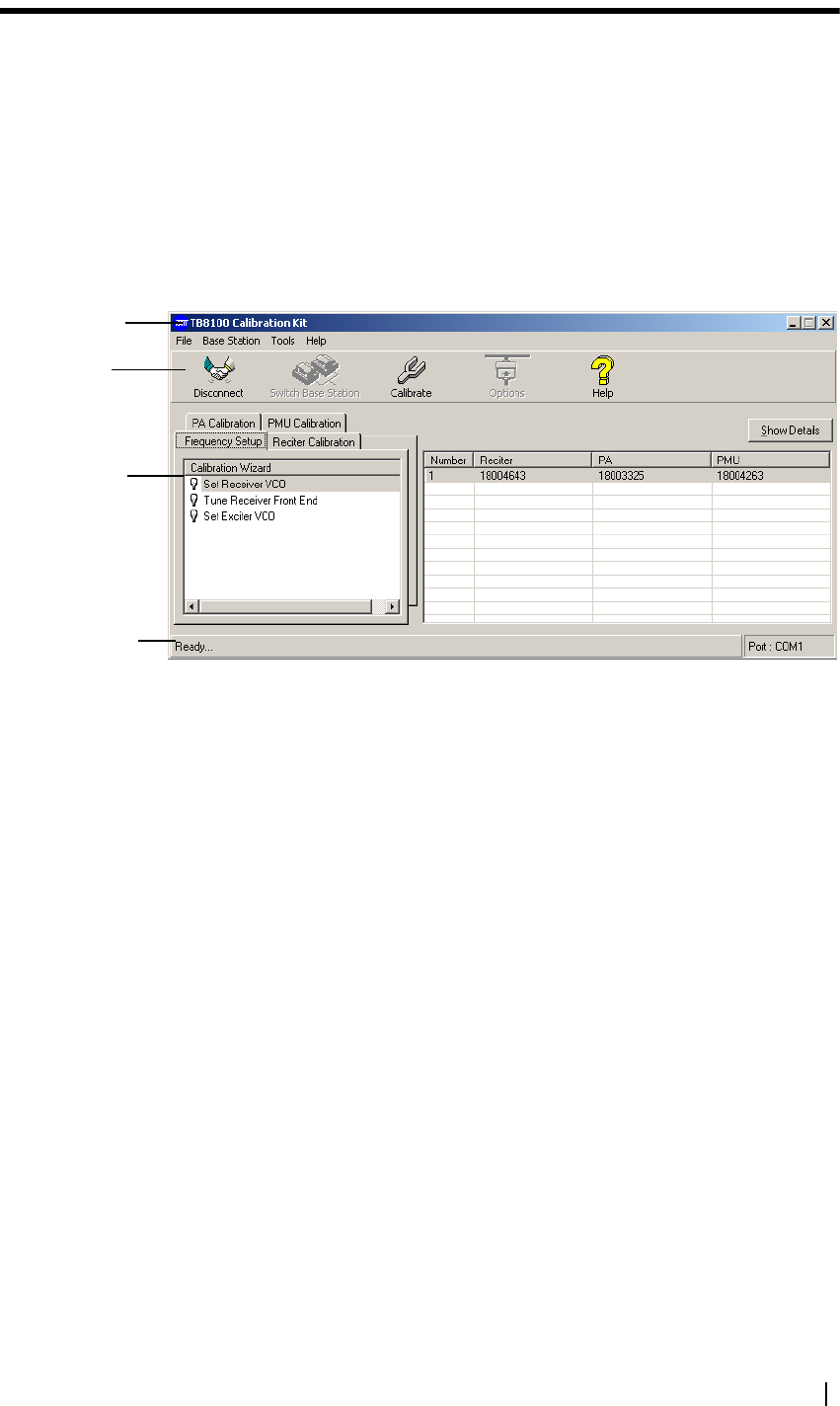
When you start the TB8100 Calibration Kit, the main program window
appears.
The main program window has four tabs. The Calibration Wizards displayed
on each tab are only visible once you are connected to the reciter or the base
station.
When the TB8100 Calibration Kit is connected to the reciter or base station,
you can view further details (such as module number, type, serial number, band,
and hardware version) about the currently selected module by clicking Show
Details.
Frequency Setup
tab Shows the three Calibration Wizards that take you step-by-step through the
frequency setup.
Reciter Calibration
tab Shows the seven calibration procedures that you can perform on the reciter.
The Calibration Wizard takes you step-by-step through the procedure you
have selected.
PA Calibration tab Shows the four calibration procedures that you can perform on the power
amplifier. The Calibration Wizard takes you step-by-step through the
procedure you have selected.
PMU Calibration
tab Shows the procedure that you can perform on the PMU.
Menu bar
Toolbar
Calibration
Wizards
Status bar
2 Using the TB8100 Calibration Kit © Tait Electronics Limited 2005
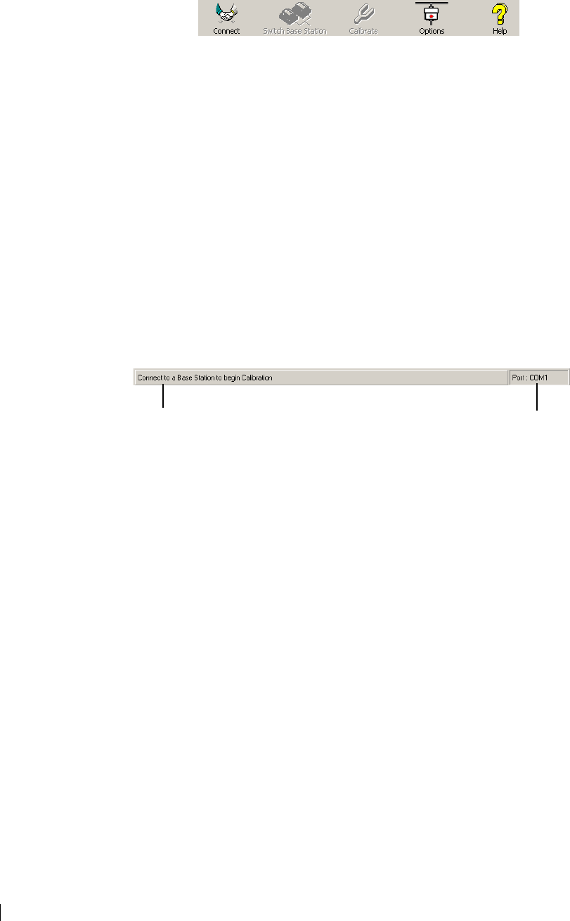
About the Toolbar
The toolbar gives you quick access to commonly used menu commands. For
example, instead of selecting Base Station > Calibrate, you can click the
Calibrate icon on the toolbar.
Connect Connects the TB8100 Calibration Kit to the base station and opens the
communication channels.
Switch Base
Station Lets you select another base station to calibrate if there are multiple base stations
in the rack (not currently supported).
Calibrate Runs the Calibration Wizard for the currently selected task.
Options Allows you to set the COM port and default calibration mode.
Help Opens the online help for the window you are currently in.
About the Status Bar
The status bar provides you with useful information that supplements the
display in the main window.
Miscellaneous messages COM port in use
TB8100 Calibration Kit User’s Manual Equipment Required 3
Equipment Required
You need the following equipment for field calibration:
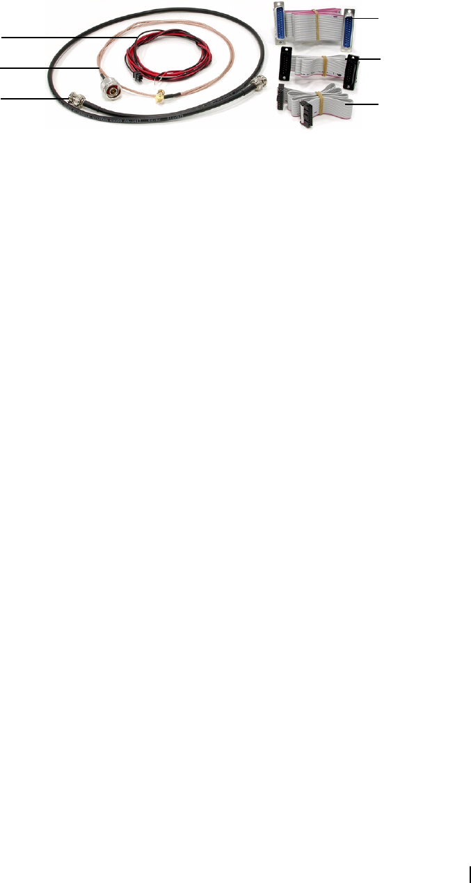
■Calibration and test unit (CTU) (order code TBA0ST1) which comes with
the cables you will need for connection to the reciter/PA and the PC. For
more information about the CTU, please refer to TN-778 The TB8100
Calibration and Test Unit.
■Calibration test kit (order code TBA0ST2) which comprises tuning tools
and the required screwdrivers in a tool pouch
■10-30 V DC power supply
■RS-232 cable
■RF attenuator (optional – depends on the setup)
You may need the following additional equipment for a service center
calibration:
■Frequency counter
■Modulation meter
■RF signal source
■AC millivoltmeter (one with a differential input may be required for
“Calibrating the Balanced Lines” on page 18)
Refer to the individual procedures for equipment setup diagrams.
Calibration Overview
Any calibration process creates digital values and a calibration date, which are
stored in the base station. The Service Kit can display the date of the last
calibration. Many calibration procedures initially clear the stored digital values.
If you do not complete the procedure or the stored digital values are outside
acceptable limits, the module is left uncalibrated. An uncalibrated reciter will go
into Download mode on startup and cannot be put into Run mode. An
uncalibrated PA generates a calibration invalid alarm.
If the procedure you are performing requires access to tuning holes, you need
to remove the reciter from the subrack and connect to it via the CTU.
The following tables summarise, for each procedure, whether or not you need
to remove the reciter from the subrack, and what equipment (in addition to a
PC with the TB8100 Calibration Kit software) you will need.
25-way cable
15-way TaitNet
cable
16-way cable
Power cable
RF cable
BNC to BNC
cable
4 Calibration Overview © Tait Electronics Limited 2005
Field Calibration
The following procedures can be carried out in the field.
Service Center Calibration
The following additional procedures may need to be carried out after a module
has been serviced.
Note: Replacing or repairing a board module may mean that the
module’s product code, product type (frequency band), serial
number, and/or hardware version need to be re-entered or altered.
To do this, your Calibration Kit needs a dongle. The Service Manual indicates
when a module detail needs re-entering or altering.
Reciter
Procedure Connection Equipment Required
Adjusting receiver lock band Outside subrack Tuning tool, CTU
Tuning the receiver Outside subrack Tuning tool (with fine metal
tip for UHF reciter), CTU
Adjusting exciter lock band Outside subrack Tuning tool, CTU
Adjusting the carrier frequency
offset
Depends on
reciter
Tuning tool, Frequency
counter, RF attenuator (only
if using PA)
Procedure Connection Equipment Required
Automatically tuning FCL Inside subrack None
Calibrating the FCL modulation Outside subrack Tuning tool, CTU,
modulation meter, RF
attenuator (only if using PA)
Calibrating the VCO modulation Outside subrack Tuning tool, CTU,
modulation meter, RF
attenuator (only if using PA)
Calibrating the RSSI Inside subrack RF signal source
Calibrating the balanced lines Inside subrack CTU, AC millivoltmeter
(perhaps with differential
input)
Calibrating the unbalanced lines Inside subrack CTU, AC millivoltmeter
TB8100 Calibration Kit User’s Manual Selecting the Communications Port 5
Power Amplifier
Power
Management Unit
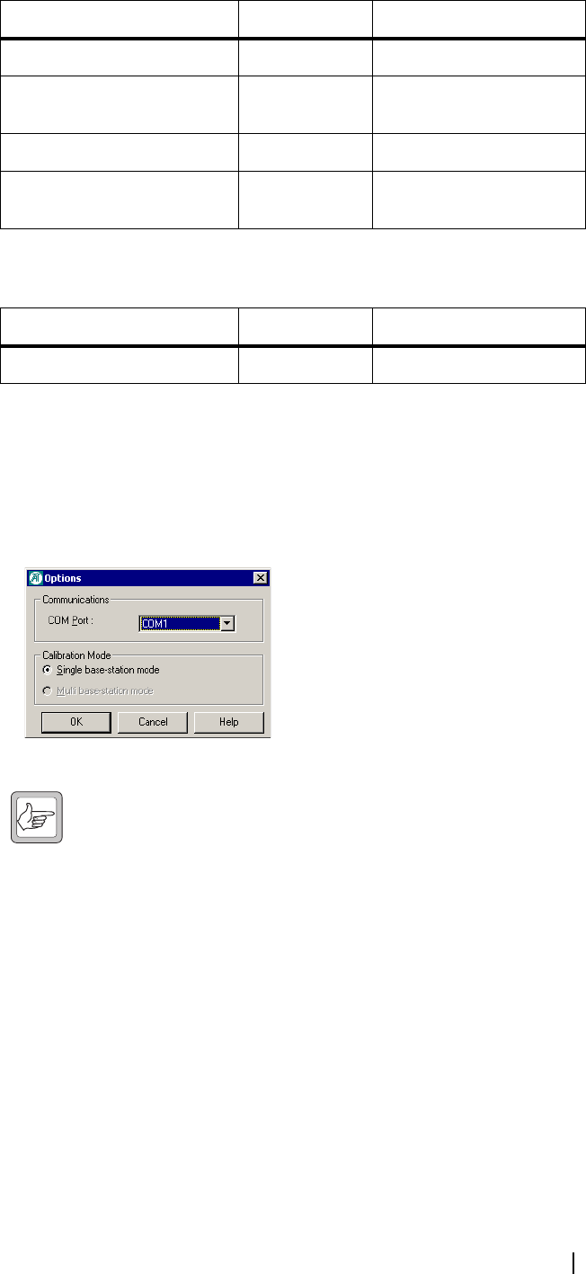
Selecting the Communications Port
Before you connect to a base station, you should first define the
communications (COM) port that you want to use.
To select the COM port
1. Select Tools > Options.
2. Select the port that you want to use from the COM Port list.
Note: The available COM ports are detected by the program and
appear in the list.
3. Click OK.
The COM port you selected is now shown on the status bar.
Connecting to a Reciter Outside the Subrack
Field calibration procedures require access to the tuning holes, so you need to
remove the reciter from the subrack and connect to it using a CTU.
Equipment ■Calibration and test unit (CTU)
■An IBM compatible PC
■10-30 V DC power supply
■16-way cable
■RS-232 cable
Procedure Connection Equipment Required
Calibrating the PA bias Inside subrack None required
Calibrating the forward &
reverse detector bias voltages
Inside subrack None required
Calibrating the PA power Inside subrack None required
Storing supply voltages Inside subrack Variable voltage external
power supply
Procedure Connection Equipment Required
Output voltage calibration Inside subrack Digital multimeter
6 Connecting to a Reciter Outside the Subrack © Tait Electronics Limited 2005
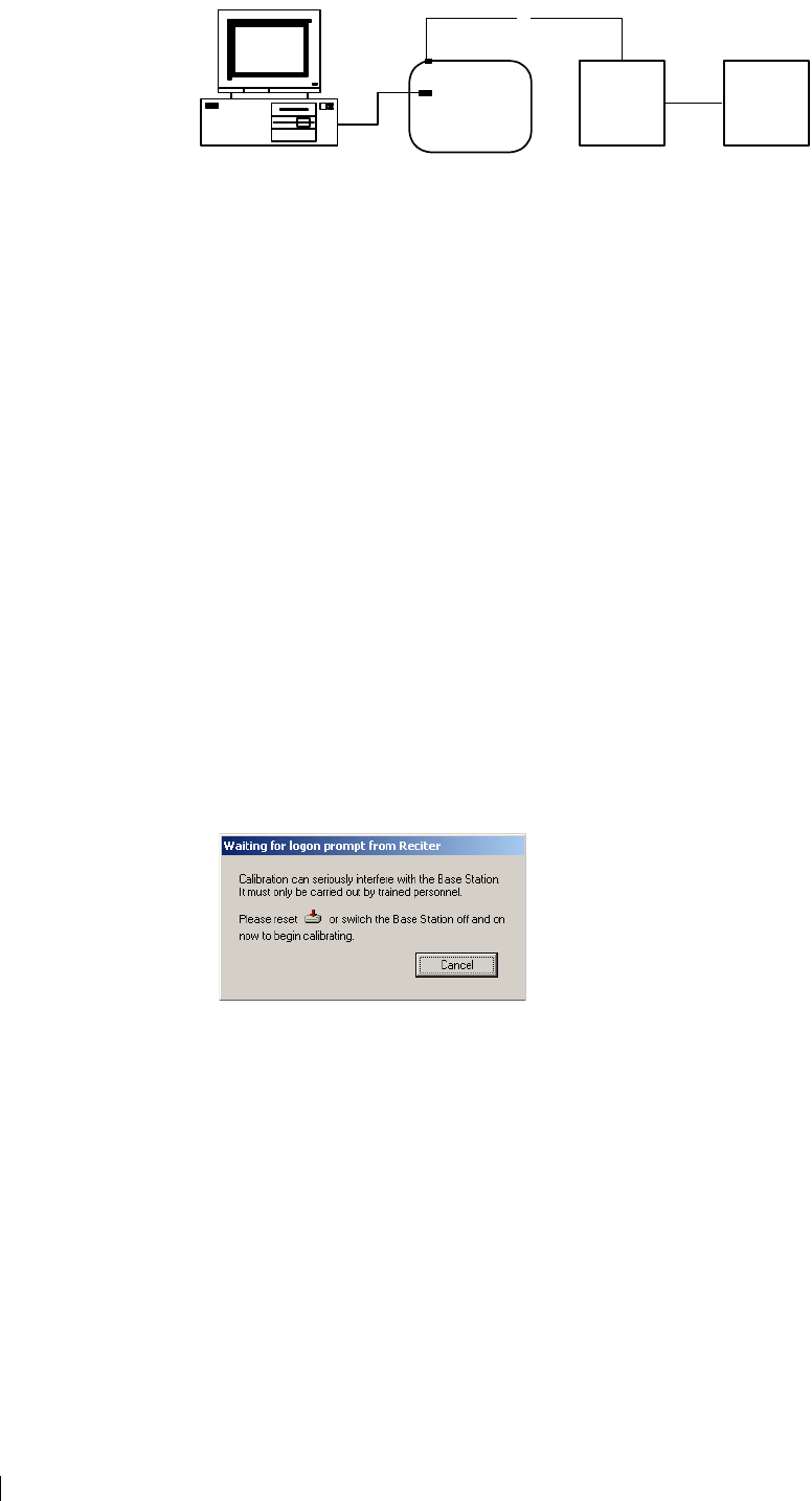
Setup
To connect to the reciter
1. Remove the reciter from the subrack (for instructions, see the Installation
and Operation Manual).
2. Set up the equipment as follows.
■Connect the reciter to the calibration and test unit (CTU) using the 16-
way cable.
■Connect your computer to the CTU by plugging the RS-232 cable into
the programming port.
■Using the power cable supplied in the calibration test kit, connect the
reciter to the 10-30 V DC power supply, but do not power it up yet.
3. Start the TB8100 Calibration Kit program, and check that the correct COM
port is selected.
4. Click Connect to start the connection process.
5. When you see the “Waiting for logon prompt from Reciter” screen, power
up the reciter. If it is already on, turn it off, and then on.
6. When the TB8100 Calibration Kit program has successfully connected to
the reciter, the Calibration Wizards are displayed in the main window.
You are now ready to tune and calibrate the reciter.
3
6
4
5
2
1
7
8
1PC 516-way cable
2RS-232 cable 6Reciter
3CTU 7Power cable
4Programming port 810-30 V DC power supply
TB8100 Calibration Kit User’s Manual Connecting to a Reciter via the Control Panel 7
Connecting to a Reciter via the Control Panel
For calibration procedures that do not require access to tuning holes, you can
leave the reciter in the subrack and connect your PC to the control panel as
follows.
Equipment ■An IBM compatible PC
■RS-232 cable
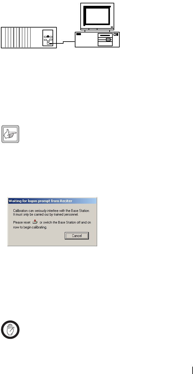
Setup
To connect to a reciter in the subrack
1. Connect your computer to the base station by plugging the RS-232 cable
into the serial port of the base station’s control panel.
Note: If the base station is fitted with a TaitNet RS232 system
interface, the control panel serial port is disabled; connect to the
serial port at the reciter rear instead.
2. Start the TB8100 Calibration Kit program, and check that the correct COM
port is selected.
3. Click Connect to start the connection process.
4. As soon as you see the “Waiting for logon prompt from Reciter” screen,
power up the base station. If it is already on, turn it off, and then on.
5. When the TB8100 Calibration Kit program has successfully connected to
the base station, the Calibration Wizards are displayed in the main window.
You are now ready to carry out calibration procedures.
Disconnecting from the Base Station/Reciter
Once calibration is completed, click Disconnect before exiting the Calibration
Kit.
Important: Disconnecting when a calibration process is not
completed may leave the base station in an uncalibrated state.
4
1
3
2
1Base station 3RS-232 cable
2Serial port 4PC

8 Troubleshooting © Tait Electronics Limited 2005
Troubleshooting
Application Errors All application errors are recorded in a log file called “CalError.log”. The data,
time, location, and any other useful information is stored in this file, which may
be helpful when troubleshooting.
The file is saved in the Logfiles subfolder of the application folder and stores up
to 1000 of the most recent logged items.
Verifying the
Software Version If you need to verify the version of the TB8100 Calibration Kit, select
Help > About.
Commands
Record All the commands sent and received by TB8100 Calibration Kit are saved in a
file called “CCTM.log”. The date, time, command number, and parameters are
all stored in this file, which may be helpful when troubleshooting.
The file is also saved in the Logfiles subfolder and stores up to 1000 of the most
recent logged items.
TB8100 Calibration Kit User’s Manual Adjusting the Receiver Lock Band 9
Adjusting the Frequency Setup
Before the TB8100 base station is installed, connected, and configured, you
must prepare it for operation by adjusting the switching range of the reciter, and
flattening the receiver response across the base station’s switching range.
Note: If the required switching range for the base station has already
been defined, you don’t need to perform these procedures.
To prepare the base station for operation
1. Adjust the receiver lock band
2. Tune the receiver front end
3. Adjust the exciter lock band
Tip: Use the TB8100 Service Kit to monitor the base station and
find out its current switching range.
Important: Be careful when using the tuning tool. Attempting to
turn the tool beyond the end of the range can crack the tuning slug.
Adjusting the Receiver Lock Band
The first step in preparing the TB8100 base station for operation is to adjust the
receiver lock band (switching range). The lock band is the range of frequencies
that the receiver is calibrated to operate on.
Equipment ■Tuning tool
■CTU
To adjust the receiver lock band
1. Remove the reciter from the subrack. (For instructions, see the Installation
and Operation Manual.)
2. Connect the Calibration Kit to the reciter (see “Connecting to a Reciter
Outside the Subrack” on page 5).
3. Select the Frequency Setup tab, and double-click Set Receiver VCO. The
Set Receiver VCO Wizard appears. The display varies, depending on the
reciter band.
4. Enter the Center Frequency (which must be a multiple of 500 kHz) of the
lock band that you want to use, and click Next.
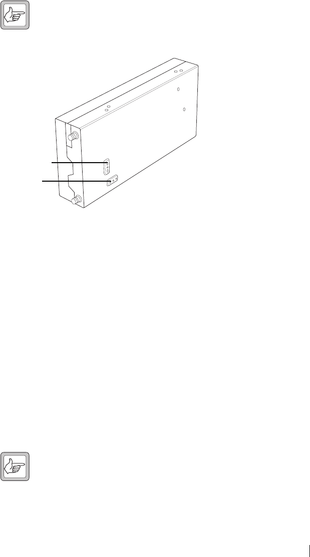
5. Insert the tuning tool into the correct receiver VCO tuning hole for the
reciter type and then click Next.
UHF receiver VCO
tuning hole
VHF receiver VCO
tuning hole
10 Tuning the Receiver Front End © Tait Electronics Limited 2005
6. Adjust the receiver VCO trimmer until the actual band matches the desired
band. The bands turn green. Click Finish. This stores the lock band in the
reciter. The icon on the Frequency Setup tab indicates that this task is
complete. Proceed to tune the front end.
Tuning the Receiver Front End
The second step in tuning the reciter frequency is to tune the receiver front
end. Tuning aims to maximise the receiver’s sensitivity and to flatten its
response across the lock band (switching range).
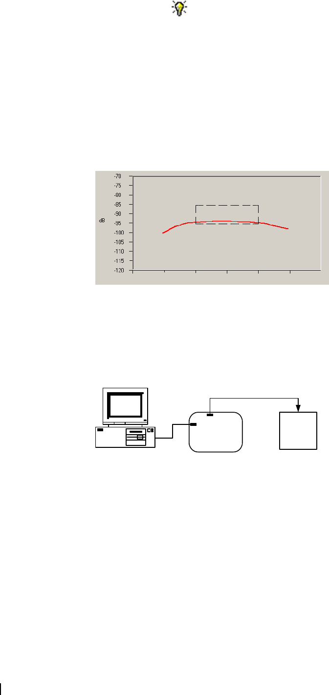
To help you do this, there is a graph of the RSSI readings in step two of the
Tune Receiver Front End Wizard. A number of RSSI readings are measured
across the switching range. These readings are then continually averaged to
produce the graph.
You should aim to achieve a response that looks something like this:
On UHF, 800 MHz, and 900 MHz reciters, you adjust helical filters. On VHF
reciters, you adjust trimmer capacitors.
Equipment ■Tuning tool
■CTU
Setup
6
4
3
1
2
5
1PC 2RS-232 cable 3Programming port
4CTU 5Noise source 6Reciter
TB8100 Calibration Kit User’s Manual Tuning the Receiver Front End 11
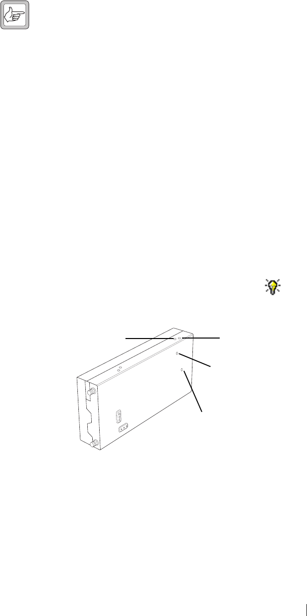
Tuning a K-Band, H-Band, or L-Band Receiver Front End
To tune the receiver front end, follow these steps.
1. Ensure you are already connected to the reciter (see “Connecting to a
Reciter Outside the Subrack” on page 5).
2. Select the Frequency Setup tab, and double-click Tune Receiver Front
End. The Tune Receiver Front End Wizard appears.
3. Connect the CTU’s noise source to the receiver input, turn the noise source
on, and then click Next.
4. Click Coarse (fast) and use the tuning tool to roughly adjust the front-end
helical filters on the receiver. As you do so, observe the graphical RSSI
readings across the lock band. Adjust first for maximum RSSI, and then for
flatness.
Note: As the response gets flatter, you may find it helpful to select a
more sensitive scale, so that you can see the graphical reading in
more detail.
Use the tuning tool as follows.
a. Insert the tuning tool into the first hole of the first set. You can start with
the hole on the left side and proceed along to the hole on the right, or
vice versa.
b. Tune each of the resonators in the first set once to give the best response.
c. Insert the tuning tool into the first hole of the second set. You can start
with the top hole and proceed down to the bottom hole, or vice versa.
d. Tune each of the resonators in the second set once to give the best
response.
e. Repeat this procedure as necessary to refine the response.
5. Once you have roughly tuned the front-end helical filters, click Fine
(slow). Repeat the above procedure to fine tune the front-end helical filters
until the response is flat in the middle of the lock band and not more than
-1 dB at the ends of the band.
Note: When using the Fine (slow) setting, you may notice a slight
delay as the reading from tuning the front-end helical filters takes
approximately one second to appear on the graph.
First set
Second set
UHF helical
filters:
12 Tuning the Receiver Front End © Tait Electronics Limited 2005
6. Click Finish. The icon on the Frequency Setup tab indicates that this
task is complete.
Tuning a VHF Receiver Front End
To tune the receiver front end, follow these steps.
1. Ensure you are already connected to the reciter (see “Connecting to a
Reciter Outside the Subrack” on page 5).
2. Select the Frequency Setup tab, and double-click Tune Receiver Front
End. The Tune Receiver Front End Wizard appears.
3. Connect the CTU’s noise source to the receiver input, turn the noise source
on, and then click Next.
4. Click Coarse (fast) and use the tuning tool to roughly adjust the four
front-end trimmers on the receiver. You can do this in any order. As you
do so, observe the graphical RSSI readings across the lock band. Adjust first
for maximum RSSI, and then for flatness.
Note: As the response gets flatter, you may find it helpful to select a
more sensitive scale, so that you can see the graphical reading in
more detail.
5. Once you have roughly tuned the trimmers, click Fine (slow). Repeat the
above procedure until the response is flat in the middle of the lock band and
not more than -1 dB at the ends of the band.
Note: When using the Fine (slow) setting, you may notice a slight
delay as the reading from tuning the trimmers takes approximately
one second to appear on the graph.
6. Click Finish. The icon on the Frequency Setup tab indicates that this
task is complete.
VHF
trimmer holes
TB8100 Calibration Kit User’s Manual Adjusting the Exciter Lock Band 13
Adjusting the Exciter Lock Band
If you are preparing the base station for operation, adjusting the exciter lock
band is the third step in tuning the reciter. Alternatively, this procedure can be
performed independently of the other two calibration wizards on the
Frequency Setup tab. Adjusting the exciter lock band defines the range of
frequencies that the base station is able to transmit on. For K-band UHF
exciters, the procedure is somewhat different: you select one of the two lock
bands instead of defining a center frequency.
Note: When performing this procedure, you don’t need to
terminate the exciter output port. An internal output pad means that
there is a good impedance match at this interface.
Equipment ■Tuning tool
■CTU
To calibrate the exciter lock band
1. Ensure you are already connected to the reciter (see “Connecting to a
Reciter Outside the Subrack” on page 5).
2. Select the Frequency Setup tab, and double-click Set Exciter VCO. The
Set Exciter VCO Wizard appears.
3. Enter the center frequency (which must be a multiple of 500 kHz) of the
lock band that you want to use, and click Next.
Alternatively, for a K-band UHF exciter, select one of the two available lock
bands. This specifies the lock band that you adjust and that the exciter oper-
ates in.
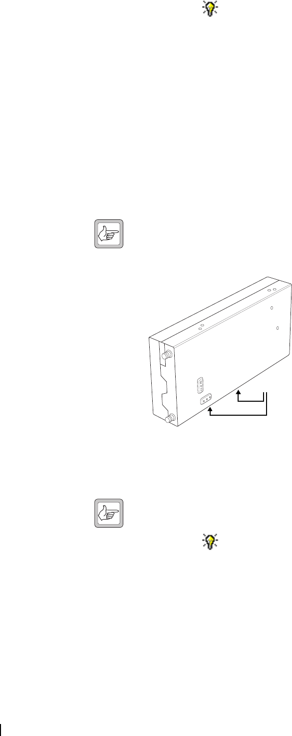
4. Insert the tuning tool into the correct exciter VCO tuning hole (see below)
and adjust the trimmer until the actual band matches the desired band. The
bands turn green. (For K-band UHF exciters, adjustment should only be
necessary if the board has been repaired.) Click Finish.
Once you have finished adjusting the exciter lock band, the icon on the
Frequency Setup tab indicates that this task is complete.
Exciter VCO tuning hole
for H-band
Exciter VCO tunin
g
hole for VHF
Exciter VCO tuning
hole for K-band
(850-870 MHz) and
L-band (852-854 MHz)
Exciter VCO tuning
hole for K-band
(762-776 MHz) and
L-band (928-941 MHz)

14 Calibrating the Exciter © Tait Electronics Limited 2005
Calibrating the Reciter
The reciter is fully calibrated in the factory, but if the reciter is serviced you may
need to perform the following procedures:
■Calibrating the Exciter
■Calibrating the RSSI
■Audio Calibration
To compensate for frequency drift, you may need to perform the following:
■Carrier Frequency Offset Adjustment (Older Reciters) or
■Carrier Frequency Offset Adjustment (Newer Reciters)
All these procedures can be done independently of each other, although it is
recommended that you tune the receiver before you calibrate the RSSI.
Important: It is recommended that only accredited service centers
and Tait engineers perform these procedures.
Calibrating the Exciter
You will need to calibrate the exciter if you have made component-level repairs
to it. There are three procedures that must all be completed in order:
1. Auto-tune the FCL
2. Calibrate the FCL
3. Calibrate the VCO
Automatically Tune the Frequency Control Loop (FCL)
Tuning the FCL calibrates the voltage levels used in the detectors for the FCL.
To automatically tune the FCL
1. Connect the Calibration Kit PC to the reciter and start the Calibration Kit.
2. Select the Reciter Calibration tab, and double-click FCL Auto Tuning.
The FCL Auto Tuning Wizard appears.
3. Click Calibrate to automatically tune the FCL.
The icon on the Reciter Calibration tab indicates that this task is complete.
You will now need to calibrate the FCL.
Calibrating the FCL
This is step two of calibrating the exciter. Once you have auto-tuned the FCL,
you should calibrate it.
Equipment ■Tuning tool
■CTU
■Modulation meter
■RF attenuator (only required if you are using a PA)

TB8100 Calibration Kit User’s Manual Calibrating the Exciter 15
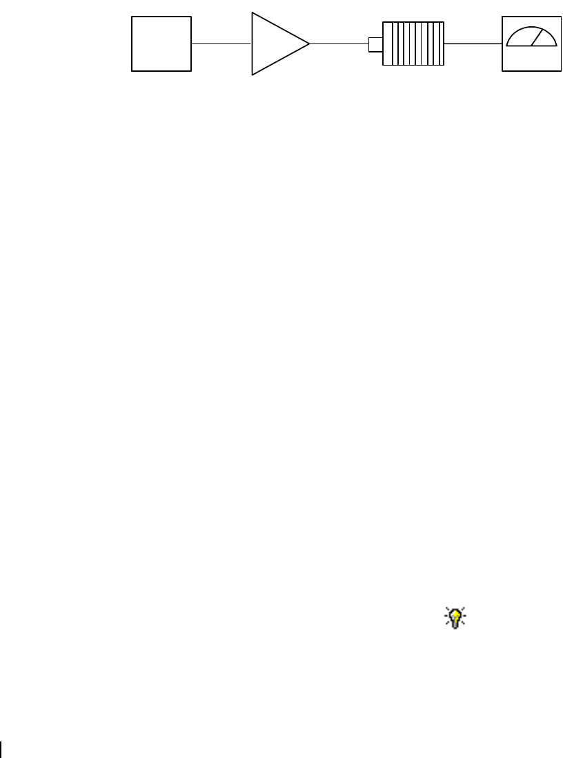
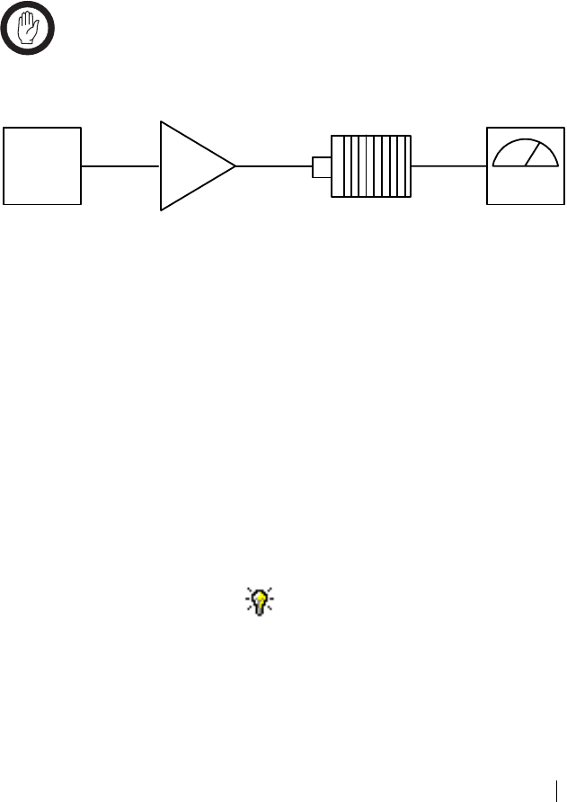
Setup
To calibrate the FCL
1. Ensure that the Calibration Kit PC is connected to the reciter.
2. Select the Reciter Calibration tab, and double-click FCL Calibration. The
FCL Calibration Wizard appears.
3. Attach an appropriate Load and Modulation meter to the PA or exciter
output, set the meter to measure the RMS deviation, and then click Next.
(If you are using a PA, it will now transmit.)
4. Insert the tuning tool into the correct exciter VCO tuning hole (see below)
and adjust the trimmer until the actual band matches the desired band. The
bands turn green. Click Next.
5. Use the slider to adjust the deviation at 1 kHz until it is 2107 Hz RMS
(3 kHz peak).
6. Select the 30 Hz Modulation Test and adjust the deviation at 30 Hz until it
is 2107 Hz RMS (3 kHz peak).
7. Repeat steps 5 and 6 until the deviation is 2107 Hz RMS at both 1 kHz and
30 Hz.
8. Click Finish. (If you are using a PA, it will now stop transmitting.)
When you have finished calibrating the FCL, the icon on the Reciter
Calibration tab indicates that this task is complete.
You will now need to calibrate the VCO.
1Reciter 3RF attenuator (only required if using a PA)
2PA (optional) 4Modulation meter
12
3
4
Exciter VCO tuning hole
for H-band
Exciter VCO tunin
g
hole for VHF
Exciter VCO tuning
hole for K-band (850-
870 MHz) and
L-band (852-854 MHz)
Exciter VCO tuning
hole for K-band (762-
776 MHz) and
L-band (928-941 MHz)
16 Calibrating the Exciter © Tait Electronics Limited 2005
Calibrating the VCO
This is step three of calibrating the exciter.
Once you have tuned and calibrated the FCL, you calibrate the VCO at
frequencies across the whole lock band. This involves selecting a sub-band,
adjusting the lock band trimmer, and then moving on-screen sliders to adjust
the deviation to 3 kHz for each of a set of frequencies.
Equipment ■Tuning tool
■CTU
■Modulation meter
■RF attenuator (only required if you are using a PA)
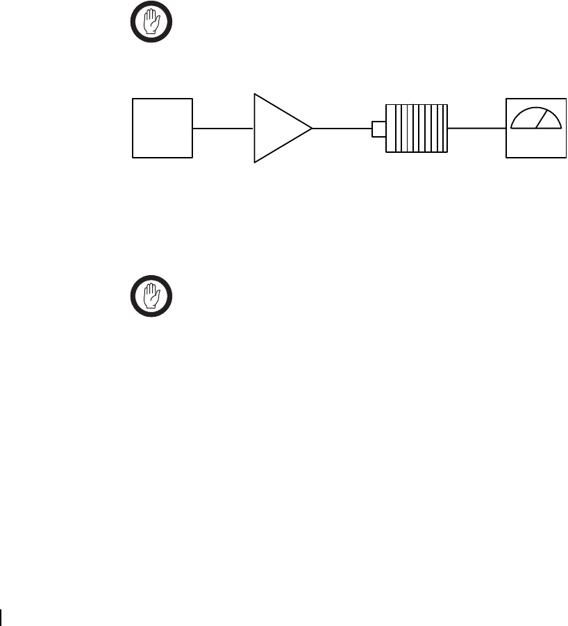
Setup
To calibrate the VCO
1. Ensure that the Calibration Kit PC is connected to the reciter.
2. Select the Reciter Calibration tab, and double-click VCO Calibration.
The VCO Calibration Wizard appears.
3. Attach an appropriate Load and Modulation meter to the PA or exciter
output, set the meter to measure the peak deviation, and then click Next.
(If you are using a PA, it will now transmit.)
4. Adjust the exciter lock band trimmer until the actual band matches the
desired band. The bands turn green.
5. Click Next. Step 3 of the wizard appears.
6. Calibrate each of the frequencies shown. Follow these steps.
a. Click the option button alongside a frequency.
b. Using the Fine and Coarse arrows, adjust the slider until the deviation
shown on the modulation meter is 3000 Hz (peak).
c. Repeat steps a) and b) until all frequencies for the band are calibrated.
This enables the Next Band button.
7. Click Next Band and repeat steps 4) through 6). Repeat until all
frequencies in all bands have been calibrated.
8. If you are connected to a K-band reciter, click Next. Select which of the
two available bands the reciter will operate on.
9. Click Finish. (If you are using a PA, it will now stop transmitting.)
When you have finished calibrating the VCO, the icon on the Reciter
Calibration tab indicates that this task is complete.
1Reciter 3RF attenuator (only required if using a PA)
2PA (optional) 4Modulation meter
1 2
3
4
TB8100 Calibration Kit User’s Manual Calibrating the RSSI 17
You should now adjust the exciter lock band because it was re-tuned several
times during this procedure. This means that the exciter is no longer on the
required frequency.
Calibrating the RSSI
Calibrating the RSSI (received signal strength indicator) ensures that the
reciter's internal RSSI values accurately reflect the actual received signal
strength. Changing the receiver's lock band can alter the calibration accuracy by
about 1 dB.
Note: Ensure that the receiver’s lock band has already been adjusted
to the required setting before carrying out this procedure. (See
“Adjusting the Receiver Lock Band” on page 9.)
Equipment ■RF signal source
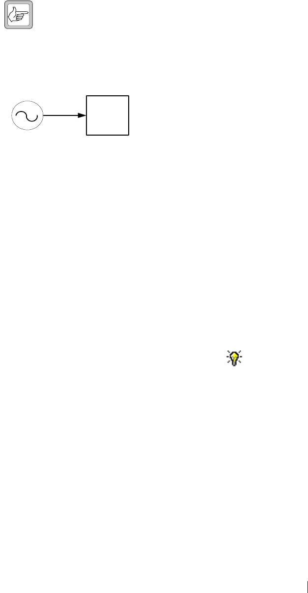
Setup
To calibrate the RSSI
1. Ensure that the Calibration Kit PC is connected to the reciter.
2. Select the Reciter Calibration tab, and double-click RSSI Calibration.
The RSSI Calibration Wizard appears.
3. Apply a signal (modulated at 1 kHz tone, 3kHz deviation peak) at the base
station’s center frequency. Use the CTU to confirm that the tone is being
output on the line, and then click Next.
4. Set the RF input signal to a level of -80 dBm, and then click Next.
5. Vary the RF level, and check that the value shown in the RSSI Gain Setting
box corresponds with the value shown on your test instrument. This is to
make sure the RSSI is correctly calibrated. Click Finish.
When you have finished calibrating the RSSI, the icon on the Reciter
Calibration tab indicates that this task is complete.
1
2
1RF signal source
2Reciter
18 Audio Calibration © Tait Electronics Limited 2005
Audio Calibration
You should calibrate the audio outputs/inputs if the system interface has been
replaced or changed at all.
Note: The balanced and unbalanced lines can be calibrated
independently of each other.
Calibrating the Balanced Lines
Calibrating the balanced lines adjusts their gain, so that when you set line levels
using the TB8100 Service Kit software, the actual line level correctly reflects
the Service Kit settings. (Refer to the TB8100 Service Kit User’s Manual for
further information.)
Equipment ■CTU
■AC millivoltmeter
Important: If the reciter you are calibrating has either the product
code TBA4xxx-0A0x or TBA5xxx-0A0x, its balanced line output
is not transformer isolated. Ensure that the line meter you are using
has a differential input otherwise the balanced line output will not
be calibrated properly.
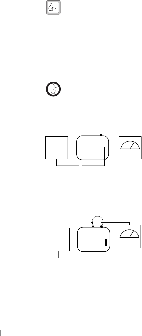
Setup for
Balanced Line Out
Setup for
Balanced Line In
16
34
2
5
1Reciter 3CTU 5Line output
225-way cable 4System interface port 6AC millivoltmeter
1
3
75
4
2
6
1Reciter 3CTU 5Line output
225-way cable 4System interface port 6AC millivoltmeter
7Line input
TB8100 Calibration Kit User’s Manual Audio Calibration 19
To calibrate the balanced input and output lines
1. Ensure that the Calibration Kit PC is connected to the reciter.
2. Select the Reciter Calibration tab, and double-click Balanced Line
Calibration. The Balanced Line Calibration Wizard appears.
3. Attach an AC millivoltmeter and terminate the balanced output in 600
ohms (either using the load on the CTU or looping the balanced output to
the balanced input), and then click Next.
4. Adjust the slider in the dialog box until the audio level on the millivoltmeter
reads 1 VPP (0.354 VRMS).
Note: Click Coarse to roughly adjust the audio level, and once you
get within range, click Fine for more precise control over the
settings. To move up or down 10 mVPP, click either side of the
slider bar.
5. Click Next. The balanced output is now calibrated.
6. Note the level of the AC millivoltmeter, and then turn off the 600 ohm
load.
7. Connect the balanced output to the balanced input. Verify that the
millivoltmeter reading is substantially unchanged. (This confirms that the
input provides a 600 ohm impedance.)
8. Click Finish. The balanced input is now calibrated.
When you have finished calibrating the balanced lines, the icon on the
Reciter Calibration tab indicates that this task is complete.
Calibrating the Unbalanced Lines
Calibrating the unbalanced lines adjusts their gain, so that when you set line
levels using the TB8100 Service Kit software, the actual line level correctly
reflects the Service Kit settings. (Refer to the TB8100 Service Kit User’s Manual
for further information.)
Equipment ■CTU
■AC millivoltmeter
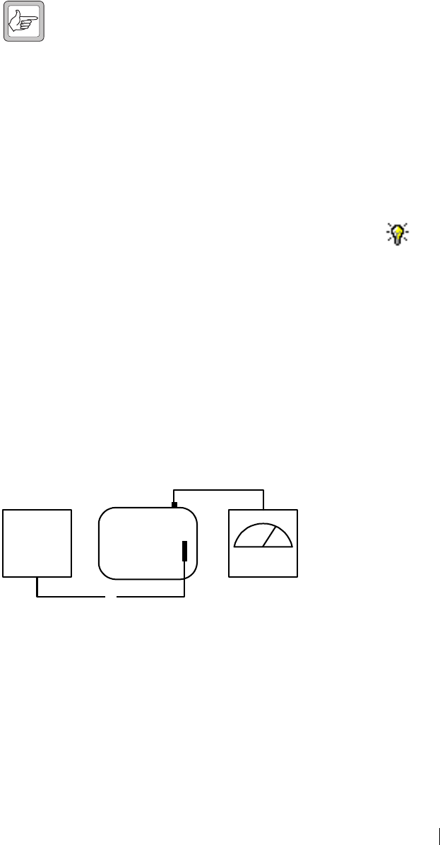
Setup for
Unbalanced Line
Out
16
34
2
5
1Reciter 3CTU 5Unbalanced line output
225-way cable 4System interface port 6AC millivoltmeter

20 Audio Calibration © Tait Electronics Limited 2005
Setup for
Unbalanced Line
In
To calibrate the unbalanced input and output lines
1. Ensure that the Calibration Kit PC is connected to the reciter.
2. Select the Reciter Calibration tab, and double-click Unbalanced Line
Calibration. The Unbalanced Line Calibration Wizard appears.
3. Attach an AC millivoltmeter to the unbalanced line output, and then click
Next.
4. Adjust the slider in the dialog box until the audio level on the millivoltmeter
reads 1 VPP (0.354 VRMS) to calibrate the unbalanced line output, and then
click Next.
Note: Click Coarse to roughly adjust the audio level, and once you
get within range, click Fine for more precise control over the
settings. To move up or down 10 mVPP, click either side of the
slider bar.
The unbalanced line output is now calibrated.
5. Connect the unbalanced output to the unbalanced input, and then click
Finish.
The unbalanced line input is now calibrated.
When you have finished calibrating the unbalanced lines, the icon on the
Reciter Calibration tab indicates that this task is complete.
1
3
56
4
2
1Reciter 3CTU 5Unbalanced line input
225-way cable 4System interface port 6Unbalanced line output
TB8100 Calibration Kit User’s Manual Carrier Frequency Offset Adjustment (Older Reciters) 21
Carrier Frequency Offset Adjustment
(Older Reciters)
The carrier frequency is derived from a reference frequency generated by the
reciter’s TCXO (temperature compensated crystal oscillator). The reference
frequency can drift over time, causing an offset to the carrier frequency. When
you connect to a reciter with hardware version 00.02 or earlier, the Calibration
Kit provides the following procedure that enables you to adjust the carrier
frequency and remove the offset.
Reciters are delivered from the factory with a 0 offset. Carry out the following
procedure if you suspect that the base station is transmitting off-frequency.
(Off-frequency is defined as being outside the range of -1 to +1 ppm.) It is a
good idea to calibrate the TCXO every few years. Exactly how often you do
this will depend on the harshness of the conditions in which the base station is
operating.
Ideally, you should calibrate the TCXO at a room temperature of 25 +/- 5
degrees Celsius. Complete the calibration as quickly as possible since extended
transmission times increase temperature, which makes the calibration less
accurate.
Equipment ■Frequency counter
■RF attenuator (only required if you are using a PA)
Important: The accuracy of the calibrated TCXO frequency is only
as good as the accuracy of the frequency counter.
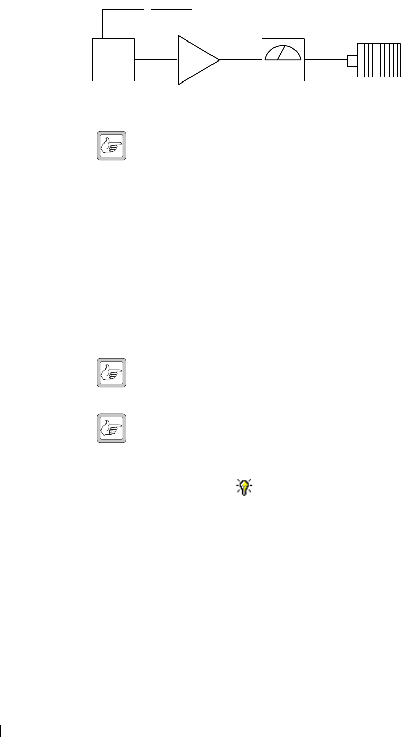
Setup
To adjust the carrier frequency
1. Ensure that the Calibration Kit PC is connected to the reciter (see
“Connecting to a Reciter via the Control Panel” on page 7).
2. Select the Reciter Calibration tab, and double-click Carrier Freq Offset
Adjustment. The Carrier Freq Offset Adjustment Wizard appears.
3. Attach an appropriate load and frequency counter (or a test set) to the exciter
or PA output, and then click Next. (This instructs the setup to transmit.)
4. Using the slider, adjust the TCXO pot until the actual frequency is exactly
the same as the selected frequency value. Click Coarse to roughly (and
quickly) adjust the output frequency, and then click Fine to fine-tune it.
When you have finished, click Finish. (The setup now stops transmitting.)
When you have finished, the icon on the Reciter Calibration tab indicates
that this task is complete.
12
3
4
1Reciter 3RF Attenuator pad (optional)
2PA (optional) 4Frequency counter
22 Carrier Frequency Offset Adjustment (Newer Reciters) © Tait Electronics Limited 2005
Carrier Frequency Offset Adjustment
(Newer Reciters)
The TCXO (temperature compensated crystal oscillator) provides a reference
frequency from which all other RF frequencies are derived. Reciters with
hardware version 00.03 and above have a voltage-controlled TCXO, with a pot
for adjusting the reference frequency to remove any carrier frequency offset.
The Carrier Freq Offset Adjustment wizard provides assistance with this
procedure.
Tait recommends that the reciter TCXO is recalibrated after 3 months service
and that annual checks are made thereafter in order to compensate for
frequency drift. Recalibration ensures that the SDB (signal displacement
bandwidth) is within 250 Hz.
The TCXO has a frequency stability of 0.5ppm (parts per million)
corresponding to 250Hz at a carrier frequency of 500MHz. Tait recommends
that the TCXO is calibrated to within 0.1ppm.
Equipment ■Torx 10 screwdriver (to remove the reciter cover)
■Tuning tool
■Frequency counter
■RF attenuator (only required if you are using a PA)
Important: The accuracy of the calibrated TCXO frequency is only
as good as the accuracy of the frequency counter.
Setup
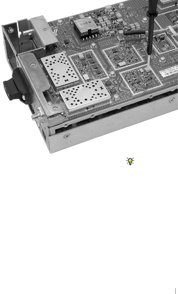
You need direct access to the TCXO circuitry on the reciter RF board. This
involves removing the reciter RF cover.
Important: The reciter contains devices that are susceptible to
damage from static charges. You must handle these devices
according to the recommended ESD precautions.
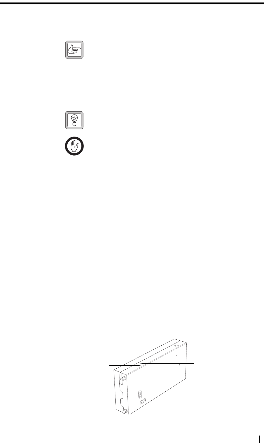
To adjust the carrier frequency
1. Remove the reciter from the subrack.
2. Remove the M3 Torx screws securing the reciter RF cover to the heatsink
and to the front and rear panels. (The RF side of the reciter can be identified
by the two BNC connectors on that side of the reciter’s rear.) Lift off the
RF cover.
3. Connect the Calibration Kit to the reciter (see “Connecting to a Reciter
Outside the Subrack” on page 5).
4. Select the Reciter Calibration tab, and double-click Carrier Freq Offset
Adjustment. The Carrier Freq Offset Adjustment wizard appears.
12
3
4
1Reciter 3RF Attenuator pad (optional)
2PA (optional) 4Frequency counter
TB8100 Calibration Kit User’s Manual Carrier Frequency Offset Adjustment (Newer Reciters) 23
5. Attach an appropriate load and frequency counter (or a test set) to the exciter
or PA output, and then click Next.
The exciter now begins transmitting on the center frequency of its lock
band. The Wizard displays a message similar to the following:
“Adjust RV1400 to set frequency within 0.1ppm or 48Hz of 485MHz”
6. Use the tuning tool to adjust the TCXO tuning control (RV1400) so that
the reciter is transmitting exactly on frequency.
7. Click Finish. Transmission ceases and the icon on the Reciter
Calibration tab indicates that this task is complete.
8. Replace the reciter RF cover, as follows.
a. Slide the cover into place over the front and rear panels. Make sure the
holes in the cover line up with the threaded holes in the heatsink and
front and rear panels.
b. Press the cover firmly into place and screw in the M3 Torx screws, first
on the flat face, then on the edge face.

24 Calibrating the PA Bias © Tait Electronics Limited 2005
Calibrating the Power Amplifier
The PA is fully calibrated in the factory, but if the PA is serviced you may need
to perform the following procedures:
■Calibrating the PA Bias
■Calibrating the Forward and Reverse Detector Bias Voltages
■Calibrating the PA Power
■Calibrating the Supply Voltage
Perform the procedures in the above order.
Important: It is recommended that only accredited service centers
and Tait engineers perform these procedures.
Calibrating the PA Bias
The driver and final transistors of the power amplifier must be biased at a
constant current. Since the characteristics of individual transistors vary slightly,
the bias current is calibrated for each device.
If either the driver or final transistor, or the PCB modules themselves, are
replaced during servicing, you should perform this procedure to calibrate the
bias current for the new device.
The bias current required for each amplifier stage is stored within the PA.
During the calibration process, the microprocessor adjusts the gate bias voltage
to obtain the required bias current for each stage.
The stage bias calibration sets up the amplifier’s DC operating conditions.
These DC conditions will be upset if there is RF present during calibration. It
is important to disconnect the RF cable from the PA input to avoid this.
The other conditions which must be met to ensure a successful calibration are
as follows:
■No other Calibration Wizards are running
■The supply voltage is within the range 27-29V
■The temperature of each stage is within the range 5-50°C
To calibrate the PA stage bias current
1. Ensure that the Calibration Kit PC is connected to the base station.
2. Select the PA Calibration tab, and double-click Calibrate PA Bias.
3. Ensure that the exciter RF is isolated from the PA by disconnecting the
SMA connector on the PA front panel.
4. Click Calibrate to calibrate the PA bias.
When you have finished calibrating the power amplifier bias, the icon on
the PA Calibration tab indicates that this task is complete.

TB8100 Calibration Kit User’s Manual Calibrating the Forward and Reverse Detector Bias Voltages 25
Calibrating the Forward and Reverse Detector Bias Voltages
The RF detectors, used for measuring the forward and reverse power, operate
with a small bias current. The resulting bias voltage from each detector (with
no RF present) is read and stored inside the PA. These voltages are used when
calculating the Antenna VSWR (Voltage Standing Wave Ratio).
You should calibrate the forward and reverse detector bias voltages:
■If the Low Pass Filter (LPF)/directional coupler PCB module is replaced
■After servicing of any components in the detector circuitry (such as the
detector diodes) on the LPF/ directional coupler PCB
To calibrate the forward and reverse detector bias voltages
1. Ensure that the Calibration Kit PC is connected to the base station.
2. Select the PA Calibration tab, and double-click Calibrate Fwd/Rev
Detector Bias Voltages.
3. Ensure that the PA is not transmitting and that there is no RF source present
at the PA RF input or output by disconnecting the input SMA connector
on the PA front panel and the ‘N’ type output connector from the rear of
the PA. Click Calibrate.
When you have finished, the icon on the PA Calibration tab indicates that
this task is complete.
Calibrating the PA Power
The power amplifier (PA) receives the RF signal from the reciter and amplifies
it to the required level, in watts, as requested by the reciter. The desired output
power is determined by the reference voltage for the power control loop.
The PA power control loop is calibrated at a single frequency, generally in the
center of the operating band.
You perform the calibration procedure to define – for each power level – the
reference DAC (Digital-to-Analogue Converter) value and forward detector
voltage.
You should only need to re-calibrate the PA power if:
■The Low Pass Filter (LPF)/directional coupler PCB module is replaced
■Any repairs are carried out on the forward and reverse detector circuitry on
the Low Pass Filter/directional coupler PCB module
■You require a more accurate power calibration on a specific frequency
Equipment
■Either an inline power meter and 50 ohm load with a high power rating, or
■A terminating power meter and appropriate 50 ohm attenuator with a high
power rating
26 Calibrating the PA Power © Tait Electronics Limited 2005
Setup for Inline
Power Meter
Note: Cables and connectors can easily cause a power loss of several
watts if either too long or poorly terminated. Always use the
shortest possible leads (or connectors instead of leads) between the
PA and power meter set-up.
To calibrate the PA transmit power
1. Ensure that the Calibration Kit PC is connected to the base station.
2. Select the PA Calibration tab, and select Calibrate PA Power.
3. Ensure that the power meter and a 50 ohm load (VSWR < 1.2:1) with a
high power rating are connected to the power amplifier RF output, and
then click Next.
4. Check that the PA RF input is connected to the reciter RF output, and that
the PA and the reciter are connected by a control bus, and then click Next.
5. For each power level shown, use the slider to adjust the DAC setting to get
the required power output, and then click Next Power to move to the next
line.
Note: Click Coarse to roughly adjust the DAC setting, and once
you get within range, click Fine for more precise control over the
settings. To move up or down one DAC value, click either side of
the slider bar.
Note: You must perform the calibration in sequence from the lowest
to the highest step. The DAC setting must be greater than the
previous one otherwise the value will not be stored in the PA, and
you cannot move to the next line.
6. When you have completed adjusting the DAC settings, click Finish.
When you have finished, the icon on the PA Calibration tab indicates that
this task is complete.
Troubleshooting Tips
DAC Settings When you adjust the DAC settings, the values for the DAC Setting, Coupler
Fwd Voltage, and Control Voltage should always increase as the power level
increases. If these values do not increase, there is either a fault with the PA or
the previous step was not calibrated correctly. If you make a mistake in the
calibration table, you must start again from step 1.
Control Voltage The Control Voltage is shown in the table to indicate the operation point
within the power control loop. The range of the control voltage is from 0 V to
7.5 V. If the control voltage reaches its limit before achieving maximum power
in the table, this indicates either a faulty gain stage in the PA or low RF input
power to the PA.
1 3
2
4
5
1Reciter 3PA 5Load
216-way cable 4RF Power Meter

TB8100 Calibration Kit User’s Manual Calibrating the Supply Voltage 27
VSWR The VSWR (Voltage Standing Wave Ratio) is monitored at the RF output of
the PA during calibration. The software will not allow calibration into a load
VSWR > 1.3:1. If a calibration step cannot be stored, check that the load
VSWR is <1.3:1. It is recommended that the load should have an input
VSWR <1.2:1.
Calibrating the Supply Voltage
The Calibrate Supply Voltage procedure stores DAC values for a set of
different PA supply voltages. These values are used by the PA’s high and low
voltage alarms and for power foldback and shutdown.
Calibrating the supply voltage is only done if you have replaced the PA control
board or its EEPROM IC. An accredited service center must first re-program
the PA with its product code, PA type, and serial number. All other PA
calibration procedures also become necessary.
Equipment ■Variable voltage power supply
■Made-up adapter cable to connect the PA power input to the power supply,
with a “Chocolate block” screw connector at one end and (for example)
banana plugs at the other.
Important: Do not attempt this procedure without a variable voltage power
supply. You could be left with a PA that will not transmit.
To calibrate the PA power supply voltage
1. Connect the calibration kit to the base station.
2. Connect the variable voltage power supply to the PA as follows. (The PA
can be in or out of the subrack, as long as it is connected via the I2C bus.),
a. Remove the PA power connector from the socket in the PMU.
b. To make sure that you don’t re-connect the power cable with the wrong
polarity, mark the green connector to indicate which side is positive and
which is negative.
c. Remove the PA’s power cable from the green connector and connect it
to the “Chocolate block” screw connector on the made-up cable.
d. Connect the other end of the cable to the variable voltage power supply.
3. Select the PA calibration tab, and double-click Calibrate Supply Voltage.
The Calibrate Supply Voltage wizard appears.
4. Check that everything is connected correctly, and then click Next.
5. Set the power supply to 24.00 V as instructed, and then click Next. The PA
stores the DAC equivalent of the voltage you supplied and the wizard moves
to the next step.
6. Follow the wizard instructions (Steps 3-5) to store DAC values for 26, 30,
and 32 V. If desired, you can click Back to repeat a step.
7. When the wizard indicates that calibration is completed, click Finish.
The icon beside Calibrate Supply Voltage in the PA Calibration tab
indicates that this task is complete.
8. Re-connect the PA’s power cable to the green connector, using the marks
you made to ensure that you connect the wires the right way round.
9. Re-connect the PA to the PMU.

28 Calibrating the PMU Output Voltage © Tait Electronics Limited 2005
Calibrating the Power Management Unit
There is only one calibration procedure for the PMU: calibrating its output
voltage.
Calibrating the PMU Output Voltage
Calibrating the PMU output voltage adjusts the voltage to be 28.00 V. This
procedure is only carried out when a replacement control card or
microprocessor is fitted to the PMU. Normally, the output voltage will be
accurate without calibration.
Note: Re-calibrating the PMU output voltage may result in it failing
to meet the published specification of +/- 0.5% accuracy. This is
because control cards are calibrated in the factory under half-load,
giving a voltage that is closer to 28.00 V under varying loads.
To calibrate the output voltage
1. Connect the Calibration Kit to the base station (see “Connecting to a
Reciter via the Control Panel” on page 7).
2. Select the PMU Calibration tab.
3. Double-click Output Voltage Calibration. The Calibrate Output
Voltage wizard appears.
4. Connect a digital multimeter to the PMU output and read the output
voltage.
5. Enter the voltage into the PMU Voltage box and click Calibrate.
6. When the wizard indicates that the calibration completed successfully, click
Finish.

TB8100 Calibration Kit User’s Manual Index 29
Index
A
AC millivoltmeter
see equipment
Antenna VSWR (Voltage Standing Wave Ra-
tio) 25
audio level
calibrating 19, 20
B
balanced input
calibrating 19
balanced output
calibrating 19
band 1
entering 4
base station
connecting to 7
disconnecting from 7
bias current
required for each power level 24
RF detectors 25
C
calibration test kit
see equipment
calibration test unit (CTU)
connecting to computer 6
connecting to reciter 6
see also equipment
calibration wizards
Balanced Line Calibration Wizard 19
Calibrate Fwd/Rev Detector Bias Voltages
Wizard 25
Calibrate PA Bias Wizard 24
Calibrate PA Power Wizard 26
Calibrating Supply Voltage 27
Carrier Freq Offset Adjustment Wizard 21,
22
FCL Auto Tuning Wizard 14
FCL Calibration Wizard 15
RSSI Calibration Wizard 17
Set Exciter VCO Wizard 13
Set Receiver VCO Wizard 9
Tune Receiver Front End Wizard 11, 12
Unbalanced Line Calibration Wizard 20
VCO Band Tuning Wizard 16
COM port 5
control voltage 26
coupler fwd voltage 26
D
DAC (Digital-to-Analogue Converter)
adjusting settings 26
detector
diodes 25
detectors
forward and reverse 25
directional coupler 25, 25
driver transistor 24
E
equipment
AC millivoltmeter 18, 19
calibration test kit 3
calibration test unit (CTU) 10, 18, 19
frequency counter 21, 22
modulation meter 14, 16
power meter 25
RF attentuator 14, 16, 21
RF attenuator 22
RF signal source 17
Torx screwdriver 22
tuning tool 9, 10, 13, 14, 16, 22
exciter
adjusting lock band 13
calibrating 14, 14, 14, 16
component repairs to 14
F
FCL (Frequency Control Loop)
calibrating the modulation 14
final transistor 24
forward detector 25
calibrating bias voltage 25
frequency
calibrating 21, 22
defining center frequency 9
defining range of 13
frequency counter
see equipment
G
gate bias voltage 24

30 Index © Tait Electronics Limited 2005
H
hardware version 1
entering 4
L
lock band
definition 9
see exciter
see receiver
log files
application errors 8
commands received and sent 8
Low Pass Filter (LPF) 25, 25
M
modulation meter
see equipment
module number 1
O
operating range
see switching range
P
PA
calibrating bias current 24
calibrating RF detector bias voltages 25
calibrating the supply voltage 27
calibrating transmit power 25
connecting to 7
details 1
faulty gain stage 26
low RF input power 26
PCB module 25, 25
peak deviation
measuring 16
PMU
calibrating output voltage 28
power supply
see equipment
product code 1
entering 4
R
receiver
adjusting lock band 9
tuning front end helical filters 10
reciter
calibrating 14
connecting to 5
connecting to in subrack 7
details 1
off-frequency 21
tuning the frequency 9
Reference DAC 25
resonators
see front end helical filters
reverse detector
calibrating bias voltage 25
RF attenuator 22
see equipment
RF detectors 25
RF signal source
see equipment
RMS (root means squared)
measuring deviation of 15
RSSI (Received Signal Strength Indicator)
tuning receiver 10
S
serial number 1
entering 4
status bar 2
switching range
adjusting 9
definition 9
system interface 18
T
TCXO (Temperature Compensated Crystal
Oscillator)
calibrating 21, 22
toolbar 2
troubleshooting 8
PA power calibration 26
U
unbalanced input
calibrating 20
unbalanced output
calibrating 20
V
version
of Calibration Kit software 8
VSWR 25, 27
W
wizards
see calibration wizards