Tait TBBA4A Base Station Transceiver User Manual TB7100 Installation Guide
Tait Limited Base Station Transceiver TB7100 Installation Guide
Tait >
Exhibit D Users Manual per 2 1033 c3
TB7100 base station
Installation Guide
MBB-00003-01
Issue 1
May 2005

2TB7100 Installation Guide
© Tait Electronics Limited May 2005
Contents
1 Installation . . . . . . . . . . . . . . . . . . . . . . . . . . . . . . . . . . . . . . . . . . . . . . . . 3
1.1 Personal Safety . . . . . . . . . . . . . . . . . . . . . . . . . . . . . . . . . . . . . . . . . . . . . . . . . . 3
1.2 Equipment Safety . . . . . . . . . . . . . . . . . . . . . . . . . . . . . . . . . . . . . . . . . . . . . . . . 3
1.3 Regulatory Information . . . . . . . . . . . . . . . . . . . . . . . . . . . . . . . . . . . . . . . . . . . 5
1.4 Environmental Conditions . . . . . . . . . . . . . . . . . . . . . . . . . . . . . . . . . . . . . . . . . 6
1.5 Grounding and Lightning Protection. . . . . . . . . . . . . . . . . . . . . . . . . . . . . . . . . . 6
1.6 Recommended Tools. . . . . . . . . . . . . . . . . . . . . . . . . . . . . . . . . . . . . . . . . . . . . 7
1.7 Ventilation. . . . . . . . . . . . . . . . . . . . . . . . . . . . . . . . . . . . . . . . . . . . . . . . . . . . . 7
1.8 Installing the Base Station . . . . . . . . . . . . . . . . . . . . . . . . . . . . . . . . . . . . . . . . . 10
2 Connection. . . . . . . . . . . . . . . . . . . . . . . . . . . . . . . . . . . . . . . . . . . . . . . 13
2.1 Overview of Inputs and Outputs. . . . . . . . . . . . . . . . . . . . . . . . . . . . . . . . . . . . 13
2.2 Power Supply Connections. . . . . . . . . . . . . . . . . . . . . . . . . . . . . . . . . . . . . . . . 13
2.3 RF Connections. . . . . . . . . . . . . . . . . . . . . . . . . . . . . . . . . . . . . . . . . . . . . . . . 14
2.4 Base Station Connections . . . . . . . . . . . . . . . . . . . . . . . . . . . . . . . . . . . . . . . . . 15
Associated Documentation
MBB-00001-xx TB7100 Installation and Operation Manual.
MBB-00002-xx TB7100 Specifications Manual.
All available TB7100 product documentation is provided on the Product CD supplied with the base
station. Updates may also be published on the Tait support website. Consult your nearest Tait Dealer
or Customer Service Organisation for more information
Tuning and Configuration
If your TB7100 base station has not been tuned to your requirements at the factory, you will need
to tune the base station before operating it. To do this you will need to use the Calibration
Application software included on the Product CD, plus the TBA0ST1 calibration test unit
including the TB7100 adapter board. The TB7100 base station has been programmed with a default
software configuration and default passwords at the factory. You will need to use the Program
Application software to configure your base station to suit the requirements of your radio system.
Refer to the Calibration Application and Program Application documentation for full details on
these procedures. If a duplexer has been ordered, it will be tuned at the factory.
TB7100 Installation Guide Installation 3
© Tait Electronics Limited May 2005
1 Installation
This chapter describes how to install the TB7100 base station in a standard
19 inch rack or cabinet. It also provides some general information on safety
precautions and site requirements. We recommend that you read the entire
chapter before beginning the installation.
1.1 Personal Safety
1.1.1 Explosive Environments
Warning!! Do not operate TB7100 base station equipment
near electrical blasting caps or in an explosive
atmosphere. Operating the equipment in these
environments is a definite safety hazard.
1.1.2 Proximity to RF Transmissions
Do not operate the transmitter when someone is standing within 90cm (3ft)
of the antenna. Do not operate the transmitter unless you have checked that
all RF connectors are secure.
1.1.3 High Temperatures
Take care when handling a TB7100 base station which has been operating
recently. Under extreme operating conditions (+60°C [+140°F] ambient
air temperature) or high duty cycles the external surfaces of the TB7100 base
station can reach temperatures of up to +80°C (+176°F).
1.2 Equipment Safety
1.2.1 ESD Precautions
Important This equipment contains devices which are susceptible to
damage from static charges. You must handle these devices
carefully and according to the procedures described in the
manufacturers’ data books.
4 Installation TB7100 Installation Guide
© Tait Electronics Limited May 2005
We recommend you purchase an antistatic bench kit from a reputable
manufacturer and install and test it according to the manufacturer’s
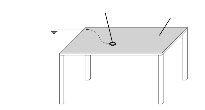
instructions. Figure 1.1 shows a typical antistatic bench set-up.
You can obtain further information on antistatic precautions and the dangers
of electrostatic discharge (ESD) from standards such as ANSI/ESD
S20.20-1999 or BS EN 100015-4 1994.
1.2.2 Antenna Load
The TB7100 base station has been designed to operate safely under a wide
range of antenna loading conditions. However, damage will occur if the load
is removed while the base station is transmitting. Transmitting into a low
VSWR will maximise the power delivered to the antenna.
1.2.3 Equipment Grounding
To ensure safe operation the TB7100 base station must be correctly
grounded as described in these installation instructions.
1.2.4 Installation and Servicing Personnel
The TB7100 base station should be installed and serviced only by qualified
personnel.
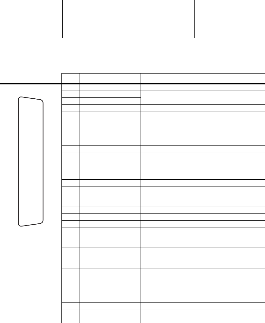
Figure 1.1 Typical antistatic bench set-up
common point ground
(building ground or
mains ground via 1M
ohm series resistor)
conductive wrist strap dissipative rubber
bench mat

TB7100 Installation Guide Installation 5
© Tait Electronics Limited May 2005
1.3 Regulatory Information
1.3.1 Distress Frequencies
The 406 to 406.1MHz frequency range is reserved worldwide for use by
Distress Beacons. Do not program transmitters to operate in this frequency
range.
1.3.2 FCC Compliance1
This device complies with part 15 of the FCC Rules. Operation is subject
to the condition that this device does not cause harmful interference.
1.3.3 Unauthorised Modifications
Any modifications you make to this equipment which are not authorised by
Tait Electronics Ltd. may invalidate your compliance authority’s approval to
operate the equipment.
1.3.4 Health, Safety and Electromagnetic Compatibility in Europe
In the European Community, radio and telecommunications equipment is
regulated by Directive 1999/5/EC, also known as the Radio and
Telecommunications Terminal Equipment (R&TTE) directive. The
requirements of this directive include protection of health and safety of users,
as well as electromagnetic compatibility.
Intended Purpose of
Product This product is an FM radio transceiver. Its intended purpose is for radio
communication in Private Mobile Radio (PMR) services or Public Access
Mobile Radio (PAMR) services.
Important This product can be programmed for frequencies or emis-
sions that may make its use illegal. A license must be
obtained before this product is used. All license require-
ments must be observed. Limitations may apply to trans-
mitter power, operating frequency, channel spacing, and
emission.
Declaration of
Conformity Brief Declarations of Conformity appear on page 18. You can download the
formal Declaration of Conformity from http://eudocs.taitworld.com/. You
can also obtain a signed and dated paper copy of the Declaration of
Conformity from Tait Europe Ltd.
1. Refer to the TB7100 Specifications Manual for more information on the compliance standards to
which the TB7100 base station has been tested and approved.
6 Installation TB7100 Installation Guide
© Tait Electronics Limited May 2005
1.4 Environmental Conditions
1.4.1 Operating Temperature Range
The operating temperature range of the TB7100 base station is –30°C to
+60°C (–22°F to +140°F) ambient temperature. Ambient temperature is
defined as the temperature of the air at the intake to the cooling fans.
1.4.2 Humidity
The humidity should not exceed 95% relative humidity through the
specified operating temperature range.
1.4.3 Dust and Dirt
For uncontrolled environments, the level of airborne particulates must not
exceed 100µg/m3.
1.5 Grounding and Lightning Protection
1.5.1 Electrical Ground
The TB7100 base station modules are grounded by physical contact
between the module mounting points and the chassis. To ensure a good
ground connection you must tighten each module securely (refer the
Installation and Operation Manual chapter “Replacing Modules” for the
correct torque).
A threaded grounding connector is provided on the rear of the tray for
connection to the site ground point (refer to the Installation and Operation
Manual chapter “Connection” for more details).
1.5.2 Lightning Ground
It is extremely important for the security of the site and its equipment that
you take adequate precautions against lightning strike. Because it is outside
the scope of this manual to provide comprehensive information on this
subject, we recommend that you conform to your country's standards
organisation or regulatory body.

TB7100 Installation Guide Installation 7
© Tait Electronics Limited May 2005
1.6 Recommended Tools
It is beyond the scope of this manual to list every tool that an installation
technician should carry. However, the following tools are specifically
required for installing the TB7100 base station:
■Phillips #2 tip screwdriver used to connect a DC power supply to the
DC input terminals of the TB7100.
■Pozidriv PZ3 screwdriver for the M6 screws used to secure the tray to
the cabinet in Tait factory-assembled systems
■Torx T10 screwdriver for the M3 pan head screws with captured shake-
proof washer and flat washer used to secure the modules in the TB7100.
■Torx T10 screwdriver for the M3 countersunk screws used to secure the
cover and the heatsink channels to the chassis of the TB7100 tray.
■Pozidriv PZ1 screwdriver for the M3 pan head self tapping screws used
to secure the fans to the fan mounting frame.
You can also obtain the TBA0ST2 tool kit from your nearest Tait Dealer or
Customer Service Organisation. It contains the basic tools needed to install,
tune and service the TB7100 base station.
1.7 Ventilation
Always ensure there is adequate ventilation around the TB7100 base station.
Do not operate at high duty cycles in a sealed cabinet. You must keep the
ambient temperature within the specified range, and we strongly
recommend you ensure that the cooling airflow is not restricted.
Important The cooling fans are mounted behind the front panel. To
ensure adequate airflow through the base station, do not
operate it for more than a few minutes with the fans discon-
nected (e.g. for servicing purposes).
1.7.1 Cabinet and Rack Ventilation
Refer to Figure 1.2 on page 9.
Adequate cooling airflow is critical to the performance of the TB7100 base
station. The cooling airflow for the TB7100 base station enters through the
front panel and exits at the rear of the tray. For optimum thermal
performance, the heated air that has passed through a base station must not
be allowed to re-enter the air intakes on the front panel.
Each TB7100 Base station requires an unobstructed airflow of 18m3/hr. (11
cfm).

8 Installation TB7100 Installation Guide
© Tait Electronics Limited May 2005
To allow enough cooling airflow through a cabinet mounted base station we
recommend the following:
■a distance of 5cm minimum clearance to any obstruction to the front of
the tray.
■an open area of at least 50 cm2 (8 in2) per tray of ventilation slots or
louvres in front of the air intakes for the fans for each tray; for example
ten 6x85mm (0.25x3.3in) slots will allow the recommended airflow.
■a distance of 10cm minimum clearance to any obstruction to the rear of
the tray.
■an open area of at least 50 cm2 (8 in2) per tray of ventilation slots or
louvres in the top of the cabinet, or to the rear of each tray.
■a 2U gap at the top of the cabinet
Note The ventilation opening must be unrestricted. If the slots or holes
are covered with a filter, mesh or grille, the open area must be
increased to allow the same airflow as an unrestricted opening.
The maximum ambient temperature entering the cabinet must not exceed
the maximum temperature specified for the base station.
If the TB7100 base station is installed in a rack or cabinet with other
equipment with different ventilation requirements, we recommend that the
TB7100 be positioned below this equipment.
Auxiliary Extractor
Fans If multiple base stations are fitted in a cabinet, auxiliary extractor fans may
be required to ensure adequate cooling. If fitted they should be capable of
extracting 18m3/hr. (11 cfm) per base station in the cabinet.
If you have any other configuration, the performance of your system will
depend on how closely you comply with the TB7100 base station airflow
requirements described above.
TB7100 Installation Guide Installation 9
© Tait Electronics Limited May 2005
Figure 1.2 Typical cabinet ventilation requirements
bventilation slots dairflow entry
cblanking panels eairflow exit
BUSY TF1 TF2 RF2
RF1 VOLUME
BUSY TF1 TF2 RF2
RF1 VOLUME
BUSY TF1 TF2 RF2
RF1 VOLUME
BUSY TF1 TF2 RF2
RF1 VOLUME
BUSY TF1 TF2 RF2
RF1 VOLUME
BUSY TF1 TF2 RF2
RF1 VOLUME
BUSY TF1 TF2 RF2
RF1 VOLUME
BUSY TF1 TF2 RF2
RF1 VOLUME
BUSY TF1 TF2 RF2
RF1 VOLUME
BUSY TF1 TF2 RF2
RF1 VOLUME
BUSY TF1 TF2 RF2
RF1 VOLUME
BUSY TF1 TF2 RF2
RF1 VOLUME
BUSY TF1 TF2 RF2
RF1 VOLUME
BUSY TF1 TF2 RF2
RF1 VOLUME
BUSY TF1 TF2 RF2
RF1 VOLUME
BUSY TF1 TF2 RF2
RF1 VOLUME
BUSY TF1 TF2 RF2
RF1 VOLUME
BUSY TF1 TF2 RF2
RF1 VOLUME
BUSY TF1 TF2 RF2
RF1 VOLUME
BUSY TF1 TF2 RF2
RF1 VOLUME
20cm
(8in)
2U
≥10cm
(≥4in)
side view front view
top view
c
c
d
e
b
c
c
10 Installation TB7100 Installation Guide
© Tait Electronics Limited May 2005
1.8 Installing the Base Station
1.8.1 Unpacking the Equipment
Unpacking the
TB7100 Base Station The TB7100 base station is packed in a strong corrugated cardboard carton
with top and bottom foam cushions.
1. Cut the tape securing the flaps at the top of the carton and fold them
flat against the sides.
2. Rotate the carton carefully onto its side and then onto its top,
ensuring that none of the flaps is trapped underneath.
3. Slide the carton upwards over the foam cushions and lift it away.
Remove the cushion from the bottom of the base station.
4. Lift the base station clear of the remaining cushion.
Disposal of
Packaging If you do not need to keep the packaging, we recommend that you recycle
it according to your local recycling methods. The foam cushions are CFC-
and HCFC-free and may be burnt in a suitable waste-to-energy combustion
facility, or compacted in landfill.
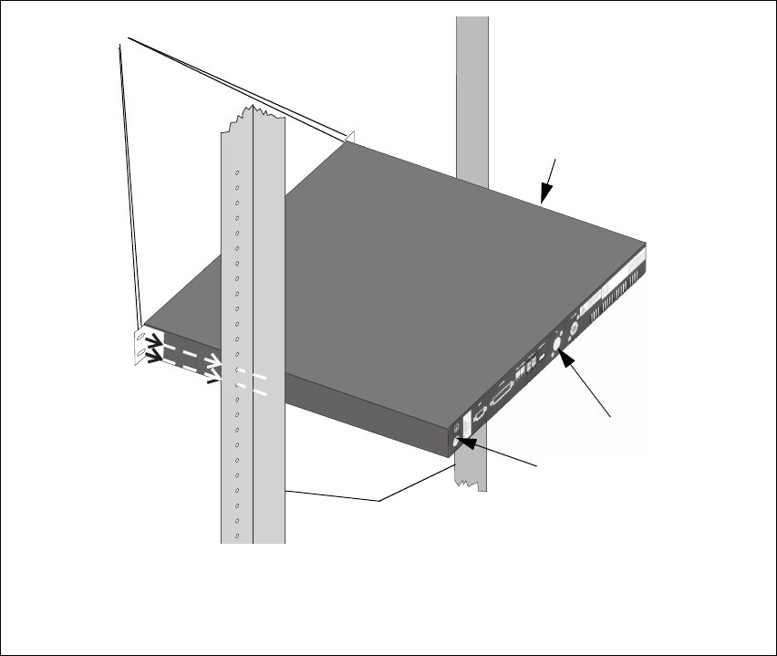
1.8.2 Mounting the base station
1. Fit the base station into the cabinet or rack and secure it firmly with
an M6 (or 0.25in if you are using imperial fittings) screw, flat and
spring washer in each of the four main mounting holes b, as shown
in Figure 1.3 on page 11.
2. The TB7100 base station can be wall mounted by rotating the front
mounting brackets and fitting the optional rear brackets (TBBA03-
01). When the TB7100 base station is wall mounted ensure the
airflow is from bottom to top (front panel mounted down) or side to
side.
3. For transport or in installations subject to vibration the TB7100
should be supported at the rear using a transit bracket. (recommended
part 302-05282-00 - TB7100 Transit Bracket)
TB7100 Installation Guide Installation 11
© Tait Electronics Limited May 2005
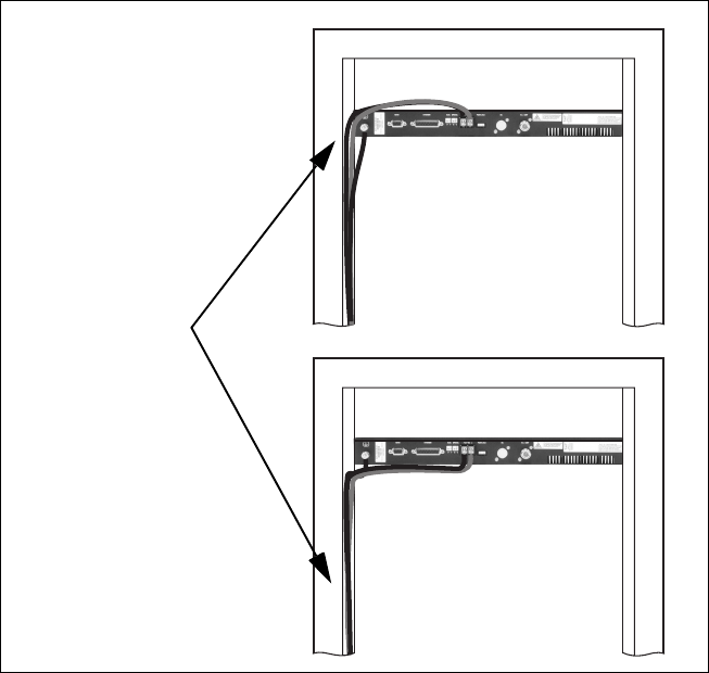
1.8.3 Cabling
General We recommend that you try to route all cables to and from the TB7100 base
station along the side of the cabinet so the cooling airflow is not restricted.
DC Power Cabling DC power cables should be well supported so that the terminals on the base
station and on the ends of the cables do not have to support the full weight
of the cables.
The Figure 1.4 on page 12 shows two recommended methods of securing
these cables to prevent straining either set of terminals.
Figure 1.3 Base station mounting points
bmain mounting holes - front eground point
cTB7100 base station frack frame
dDC connector - rear
rear view
f
d
c
e
b
12 Installation TB7100 Installation Guide
© Tait Electronics Limited May 2005
1.8.4 Power Supply Options
General The TB7100 base station can be powered by the station’s own DC supply
or by a T809-10-70Cx AC power supply.
1.8.5 Accessories
General The TB7100 base station can use the following accessories:
■T809-10-70Cx PSU
■Internal Duplexer
■Wall Mount Bracket
■TMAA02-01 fist microphone
■TMAA10-01 desk microphone
Figure 1.4 DC power cabling
secure the cables to the
cabinet to support their
weight
TB7100 Installation Guide Connection 13
© Tait Electronics Limited May 2005
2 Connection
This chapter provides information on all the inputs and outputs on the
TB7100 base station.
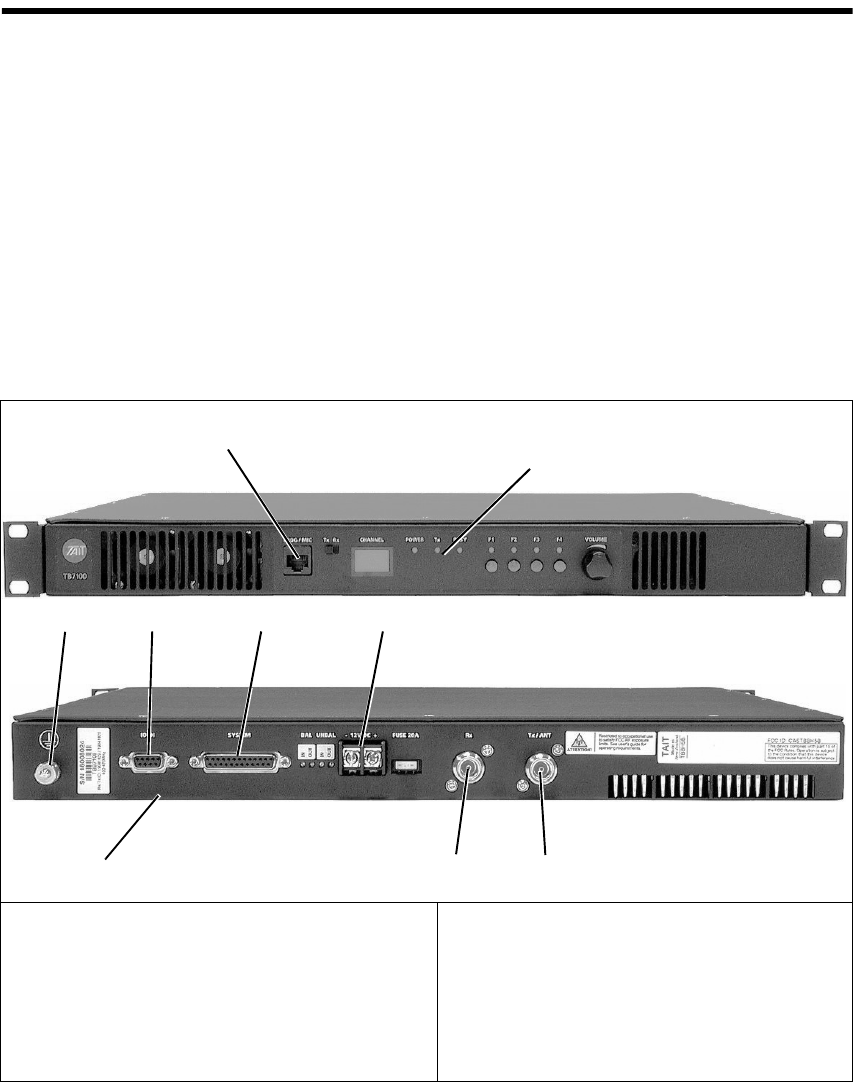
2.1 Overview of Inputs and Outputs
This section identifies the main input and output connections for the
TB7100 base station. The figure below identifies the connections at the
front and rear of the base station. Refer to the following sections in this
chapter for more details on these connections.
2.2 Power Supply Connections
DC Power The TB7100 base station is designed to accept a nominal 13.8VDC, with
negative ground.
Figure 2.1 TB7100 base station inputs and outputs
bProgramming/Microphone socket (PROG/MIC) fReceiver Antenna (Rx)
cSerial Interface (IOIOI) gTransmitter Antenna (Tx/ANT) This is transmit
and receive if a duplexer is fitted
dSystem Interface (SYSTEM) hground point
e13.8VDC Input
b
ced
h
gf
Rear
Front
14 Connection TB7100 Installation Guide
© Tait Electronics Limited May 2005
You must connect the DC supply from the battery to the base station via a
readily accessible disconnect device such as a fuse or DC-rated circuit
breaker with the appropriate rating, as shown in the table below. The DC
input leads should be of a suitable gauge to ensure less than 0.2V drop at
maximum load over the required length of lead.
Terminate the DC input leads with a suitable crimp connector for attaching
to the rear panel DC input M4 screws.
2.3 RF Connections
RF Input and Output The RF input to the TB7100 base station is via the N-type connector on
the rear panel of the base station. The RF output is via the N-type
connector on the rear panel of the base station.
We recommend that you use dual-screened coaxial cable such as RG214 for
the N-type connections.
When the base station is used in simplex mode using a single antenna with
a coaxial changeover relay, the isolation of this relay must be ≥40dB.
Nominal Supply
Voltage
Input Voltage
Range
Circuit Breaker/
Fuse Rating
Recommended
Wire Gaugea
a. For a length of 1.5m to 2m (5ft to 6.5ft) (typical).
13.8VDC 10VDC to 16VDC 20A 8AWG / 8.35mm2
Figure 2.2 Recommended DC power connection
Battery
TB7100
base station
Circuit Breaker
or Fuse
TB7100 Installation Guide Connection 15
© Tait Electronics Limited May 2005
2.4 Base Station Connections
2.4.1 Rear Panel
The rear panel has the serial interface, the system interface, the DC input
and the RF in and out connectors. Each of these is described in this section.
System Interface The system interface connector provides the following:
The pin allocations for the 25-way female D-range system interface
connector are listed in the table below.
■transformer isolated 600Ω balanced audio I/O
■opto-isolated keying
■opto-isolated gate output
■digital I/O (bidirectional)
■Tx key
■Tx relay
■Rx gate
■RSSI
System Interface Pin Signal Name Signal Type Notes
1 Rx line output + audio output transformer isolated line
2 Tx/Rx digital input 1 input high ≥1.7 V, low ≤0.7 V
3 Tx/Rx digital input 2
4 Rx line output – audio output transformer isolated line
5 Tx line input + audio input transformer isolated line
6 Tx/Rx digital input 3 input high ≥1.7 V, low ≤0.7 V
7 Tx/Rx digital input 4 input output: high ≥3.1 V (no load),
low <0.6 V (10mA sink)
input: high ≥1.7 V, low ≤0.7 V
8 Tx line input – audio input transformer isolated line
9 RSSI output DC signal
10 Tx digital in/out 1 input/output output: high ≥3.1 V (no load),
low <0.6 V (10mA sink)
input: high ≥1.7 V, low ≤0.7 V
11 Tx audio input audio input
12 Tx digital in/out 2 input/output output: high ≥3.1 V (no load),
low <0.6 V (10mA sink)
input: high ≥1.7 V, low ≤0.7 V
13 ground ground
14 Rx gate output open collector
15 Tx key input active low
16 Rx relay (comm) output
17 Rx relay (NO or NC) output
18 Rx Inhibit input
19 Rx digital in/out 1 input/output output: high ≥3.1 V (no load),
low <0.6 V (10mA sink)
input: high ≥1.7 V, low ≤0.7 V
20 Tx Opto input + input input voltage range 10VDC to
60VDC21 Tx Opto input – input
22 Rx digital in/out 2 input/output output: high ≥3.1 V (no load),
low <0.6 V (10mA sink)
input: high ≥1.7 V, low ≤0.7 V
23 Digital output/Tx relay output
24 Rx audio output output
25 13.8 volt output power output resetable SMD fuse 1.5A
external view
B
C
D
E
F
G
H
I
J
1)
1!
1@
1#
1$
1%
1^
1&
1*
1(
2)
2!
2@
2#
2$
2%
16 Connection TB7100 Installation Guide
© Tait Electronics Limited May 2005
Serial Interface The serial interface connector provides a data connection to the TB7100
base station. The pin allocations for the 9-way female D-range serial
interface connector are listed in the table below.
DC Input The DC input connector is a heavy duty M4 screw terminal connector
suitable for many forms of connection. The pin allocations for the 2-way
DC input connector are listed in the table below.
RF Connectors See earlier reference on page 14.
Ground Mounted on the rear panel in the left hand corner is a terminal for
grounding the TB7100 tray to the mounting rack.
Serial Interface Pin Signal Name Signal Type Notes
1 not connected not used
2 receive data output data transmitted by TB7100
3 transmit data input data received by TB7100
4 not connected not used
5 ground ground
6 not connected not used
7 ready to transmit output request to send
8 clear to send input clear to send
9 not connected not used
h
j
bg
i
c
d
e
f
external view
DC Input Pin Signal Name Signal Type Notes
1 13.8VDC input
2 ground input
12
External view
Bottom of TB7100
+
_
TB7100 Installation Guide Connection 17
© Tait Electronics Limited May 2005
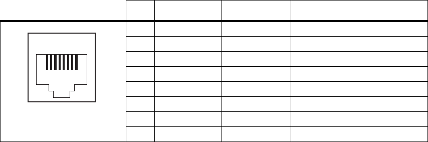
2.4.2 Front Panel
The front panel has the user interface providing the programming/
microphone connector.
Programming/
Microphone The TB7100 programming and calibration applications are connected to the
base station via the programming/microphone socket. This socket is an
8-way female RJ-45 connector. Use the T2000-A19 programming lead and
a TMAA20-04 adapter to connect your programming computer to the base
station. It is possible to plug the RJ11 directly into the RJ45 socket without
the use of the adapter, but this is not recommended. A microphone can also
be connected to the TB7100 base station via this socket. The pin allocations
for the programming/microphone socket are given in the following table.
Programming/Microphone Pin Signal Name Signal Type Notes
1 not connected not connected
2 +13V8_SW output +13.8V, 250mA
3 TXD input transmit data
4 PTT input PTT
5 MIC_AUD_IN input voice band (microphone) input
6 GND ground
7 RXD output receive data
8 not connected not connected
12345678
external view

18 TB7100 Installation Guide
© Tait Electronics Limited May 2005
Directive 1999/5/EC Declaration of Conformity
da Dansk
Undertegnede Tait Electronics Limited
erklærer herved, at følgende udstyr TBBB1A,
TBBH5A overholder de væsentlige krav og
øvrige relevante krav i direktiv 1999/5/EF.
Se endvidere: http://eudocs.taitworld.com/
de Deutsch
Hiermit erklärt Tait Electronics Limited die
Übereinstimmung des Gerätes TBBB1A,
TBBH5A mit den grundlegenden
Anforderungen und den anderen relevanten
Festlegungen der Richtlinie 1999/5/EG.
Siehe auch: http://eudocs.taitworld.com/
el Ελληνικός
Με την παρουσα Tait Electronics Limited
δηλωνει οτι TBBB1A, TBBH5A
συµµορφωνεται προσ τισ ουσιωδεισ
απαιτησεισ και τισ λοιπεσ σχετικεσ διαταξεισ
τησ οδηγιασ 1999/5/ΕΚ.
βλέπε και: http://eudocs.taitworld.com/
en English
Tait Electronics Limited declares that this
TBBB1A, TBBH5A complies with the
essential requirements and other relevant
provisions of Directive 1999/5/EC.
See also: http://eudocs.taitworld.com/
es Español
Por medio de la presente Tait Electronics
Limited declara que el TBBB1A, TBBH5A
cumple con los requisitos esenciales y
cualesquiera otras disposiciones aplicables o
exigibles de la Directiva 1999/5/CE.
Vea también: http://eudocs.taitworld.com/
fi Suomi
Tait Electronics Limited vakuuttaa täten että
TBBB1A, TBBH5A tyyppinen laite on
direktiivin 1999/5/EY oleellisten vaatimusten
ja sitä koskevien direktiivin muiden ehtojen
mukainen.
Katso: http://eudocs.taitworld.com/
fr Français
Par la présente, Tait Electronics Limited
déclare que l'appareil TBBB1A, TBBH5A est
conforme aux exigences essentielles et aux
autres dispositions pertinentes de la directive
1999/5/CE.
Voir aussi: http://eudocs.taitworld.com/
it Italiano
Con la presente Tait Electronics Limited
dichiara che questo TBBB1A, TBBH5A è
conforme ai requisiti essenziali ed alle altre
disposizioni pertinenti stabilite dalla direttiva
1999/5/CE.
Vedi anche: http://eudocs.taitworld.com/
nl Nederlands
Hierbij verklaart Tait Electronics Limited dat
het toestel TBBB1A, TBBH5A in
overeenstemming is met de essentiële eisen en
de andere relevante bepalingen van richtlijn
1999/5/ EG.
Zie ook: http://eudocs.taitworld.com/
pt Português
Tait Electronics Limited declara que este
TBBB1A, TBBH5A está conforme com os
requisitos essenciais e outras provisões da
Directiva 1999/5/CE.
Veja também: http://eudocs.taitworld.com/
sv Svensk
Härmed intygar Tait Electronics Limited att
denna TBBB1A, TBBH5A står I
överensstämmelse med de väsentliga
egenskapskrav och övriga relevanta
bestämmelser som framgår av direktiv 1999/
5/EG.
Se även: http://eudocs.taitworld.com/

TB7100 Installation Guide 19
© Tait Electronics Limited May 2005
Tait Contact Information
Tait Radio Communications http://www.taitworld.com
Corporate Head Office
New Zealand
Tait Electronics Ltd
P.O. Box 1645
Christchurch
New Zealand
E-mail: info@taitworld.com
Website: http://www.taitworld.com
Technical Support:
E-mail: support@taitworld.com
Website: http://support.taitworld.com
Tait North America
Regional Head Office - United States of
America
Tait North America Inc.
E-mail: usa@taitworld.com
Canada
Tait North America Inc.
E-mail: canada@taitworld.com
Latin America
Tait Latin America
E-mail: latinamerica@taitworld.com
Tait Europe
Regional Head Office - United Kingdom
Tait E u rope L t d
E-mail: teusales@tait.co.uk
Tait North Asia
Regional Head Office - Hong Kong
Tait Mobile Radio (Hong Kong) Ltd
E-mail: hongkong@taitworld.com
Beijing
Tait Mobile Radio (Hong Kong) Ltd
E-mail: beijing@taitworld.com
Tait South Asia
Regional Head Office - Singapore
Tait Electronics (Far East) Pte Ltd
E-mail: singapore@taitworld.com
Thailand
Tait Mobile Radio Ltd
E-mail: thailand@taitworld.com
Oceania
New Zealand
Tait Communications Ltd
E-mail: headoffice@tcl.tait.co.nz
Australia
Tait Electronics (Aust) Pty Ltd
E-mail: australia@taitworld.com
Note: For the addresses and phone numbers
of the above regional offices refer to the Tait-
World webs it e.