Tait TBBB1A Base Station Transceiver User Manual TB7100 Installation and Operation Manual
Tait Limited Base Station Transceiver TB7100 Installation and Operation Manual
UserManual.wiki
>
Tait
>
TBBB1A User Manual
Exhibit D Users Manual per 2 1033 c3
Navigation menu
Upload a User Manual
Namespaces
Wiki Guide
HTML
PDF
Info
Views
User Manual
Discussion / Help
Navigation
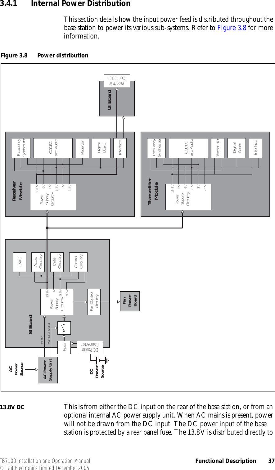
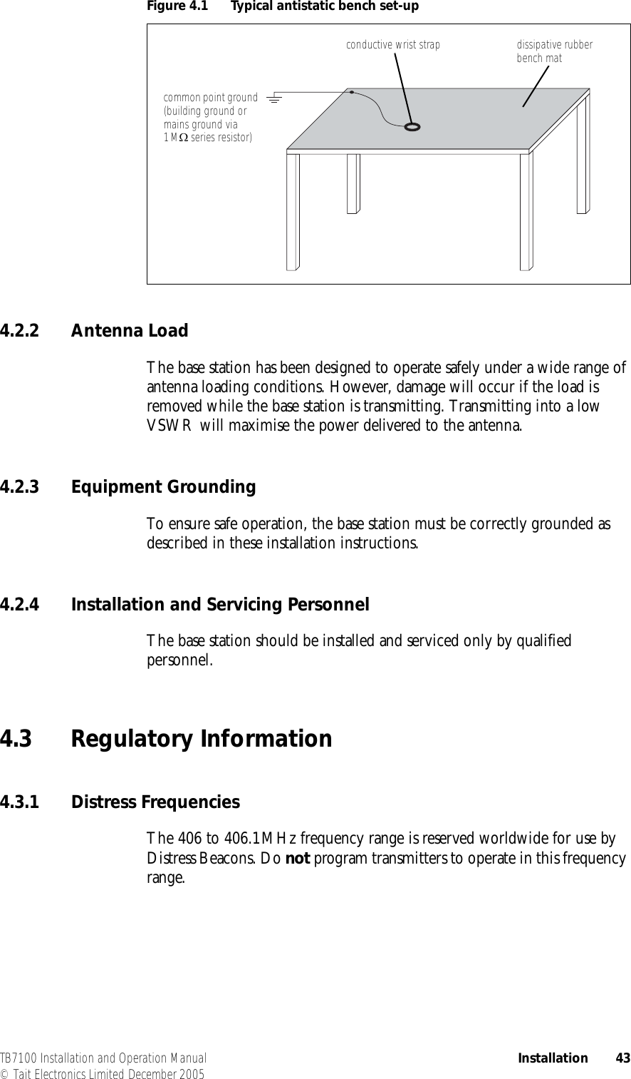
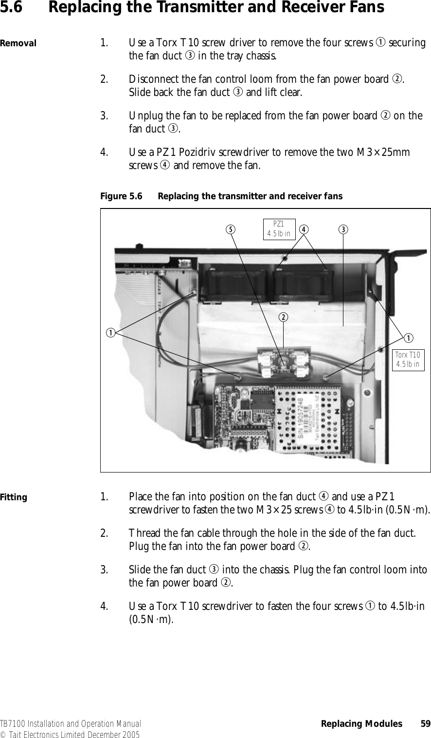
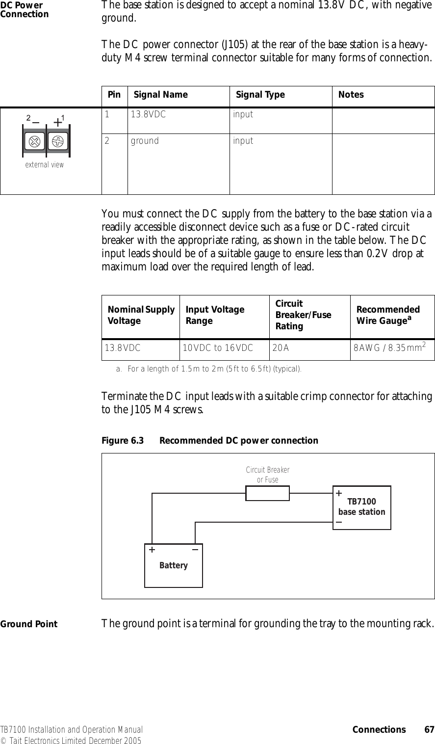
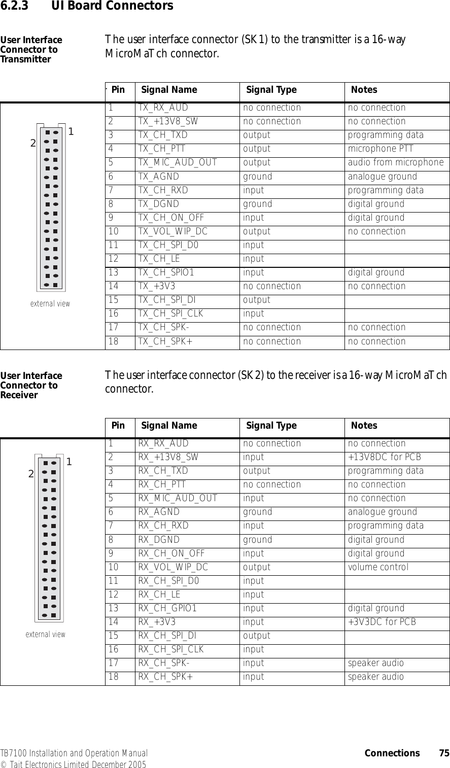
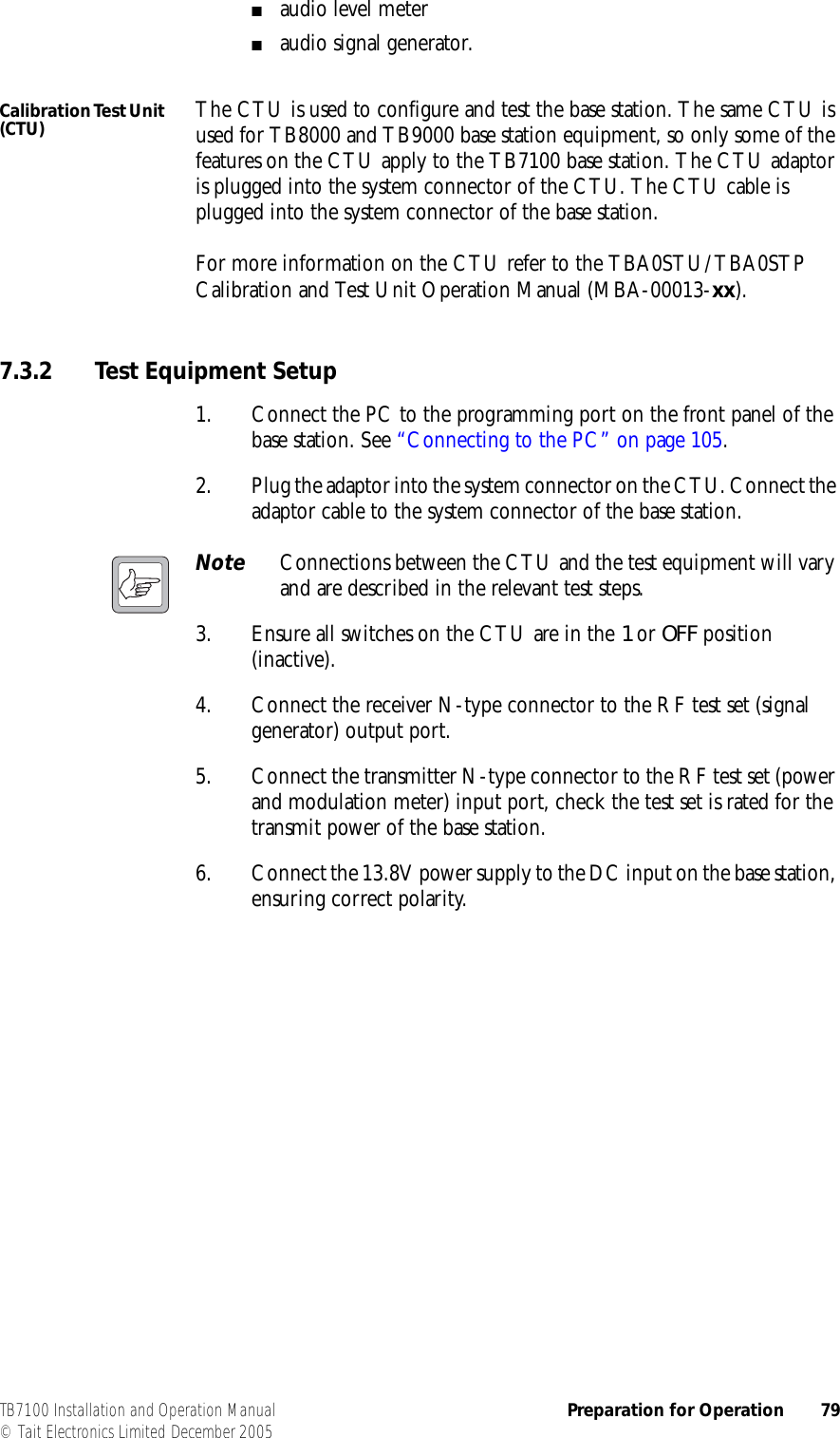
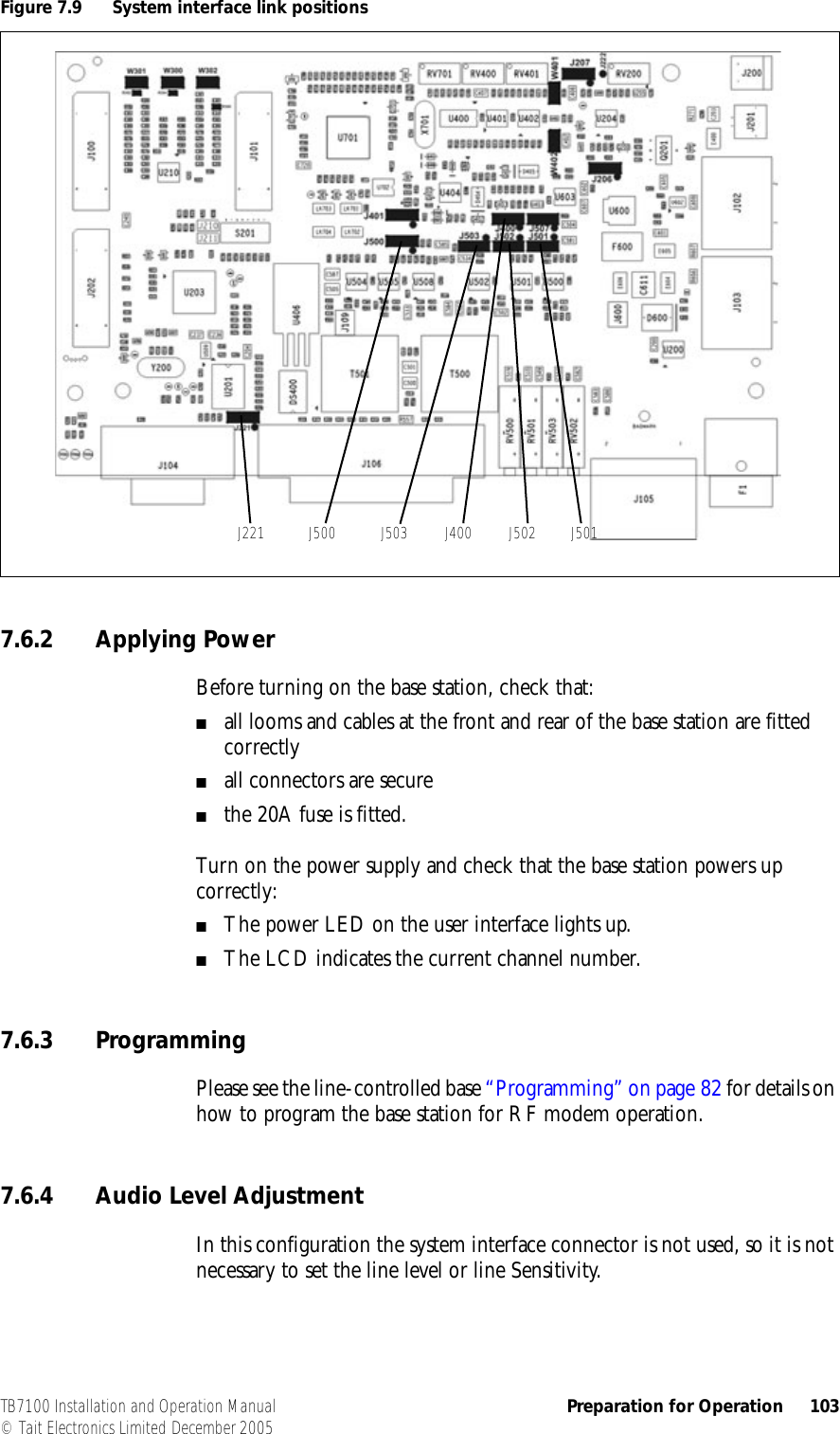
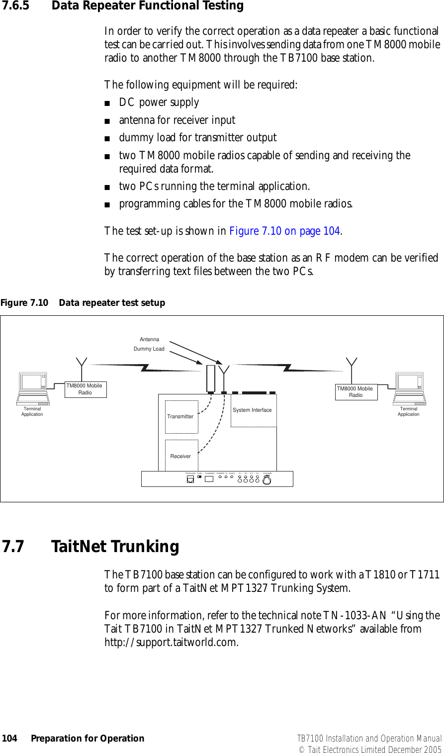
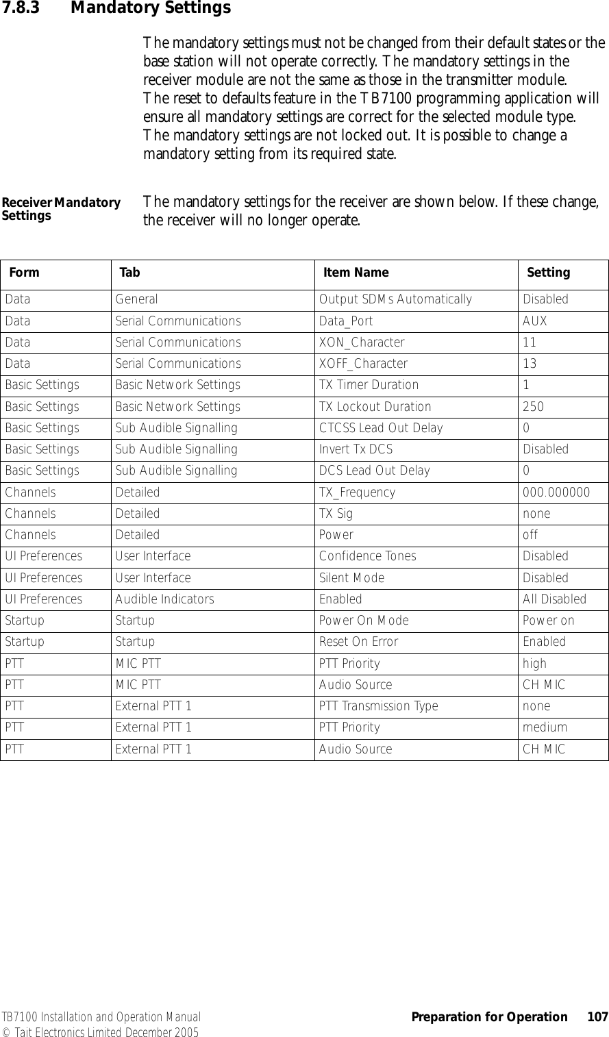
![42 Installation TB7100 Installation and Operation Manual© Tait Electronics Limited December 20054.1.2 Explosive EnvironmentsWarning!! Do not operate base station equipment near electrical blasting caps or in an explosive atmosphere. Operating the equipment in these environments is a definite safety hazard.4.1.3 Proximity to RF TransmissionsDo not operate the transmitter when someone is standing within 90cm (3ft) of the antenna. Do not operate the transmitter unless you have checked that all RF connectors are secure.4.1.4 High TemperaturesTake care when handling a base station which has been operating recently. Under extreme operating conditions (+60°C [+140°F] ambient air temperature) or high duty cycles the external surfaces of the base station can reach temperatures of up to +80°C (+176°F).4.2 Equipment Safety4.2.1 ESD PrecautionsImportant This equipment contains devices which are susceptible to damage from static charges. You must handle these devices carefully and according to the procedures described in the manufacturers’ data books.We recommend you purchase an antistatic bench kit from a reputable manufacturer and install and test it according to the manufacturer’s instructions. Figure 4.1 shows a typical antistatic bench set-up.You can obtain further information on antistatic precautions and the dangers of electrostatic discharge (ESD) from standards such as ANSI/ESD S20.20-1999 or BS EN 100015-4 1994.](https://usermanual.wiki/Tait/TBBB1A/User-Guide-816845-Page-42.png)