Tait TBCB1D Base Station Transceiver User Manual TB9300 Installation and Operation Manual
Tait Limited Base Station Transceiver TB9300 Installation and Operation Manual
Tait >
Exhibit D Users Manual per 2 1033 c3

TB9300 Installation and Operation Manual Installation 61
© Tait Limited July 2012
5Installation
This chapter provides information on the site requirements for your
TB9300 equipment and also describes how to install the base station in a
standard 19 inch rack or cabinet.
If this is your first time installing a TB9300 base station, we recommend
that you read the entire chapter before beginning the actual installation.
5.1 Before You Begin
5.1.1 Equipment Security
The security of your base station equipment is a high priority. If the site is
not fully secure, the base station should at least be locked in a secure
cabinet to prevent unauthorized access.
5.1.2 Grounding and Lightning Protection
Electrical Ground The base station modules are grounded by physical contact between the
module case and the subrack. To ensure a good ground connection you
must tighten each module retaining clamp securely (refer to “Final
Reassembly” on page 102 for the correct torque).
A threaded grounding connector is provided on the rear of the subrack for
connection to the site ground point (refer to “Connecting Up the Base
Station” on page 79 for more details).
Lightning Ground It is extremely important for the security of the site and its equipment that
you take adequate precautions against lightning strike. Because it is outside
the scope of this manual to provide comprehensive information on this
subject, we recommend that you conform to your country’s standards
organization or regulatory body.
62 Installation TB9300 Installation and Operation Manual
© Tait Limited July 2012
5.1.3 Equipment Ventilation
Always ensure there is adequate ventilation around the base station.
Notice Do not operate it in a sealed cabinet. You must keep the
ambient temperature within the specified range, and we strongly rec-
ommended that you ensure that the cooling airflow is not restricted.
Notice The cooling fans are mounted on the front panel and will only
operate when the panel is fitted correctly to the front of the subrack. To
ensure adequate airflow through the base station, do not operate it for
more than a few minutes with the front panel removed (e.g. for servicing
purposes).
5.1.4 Ambient Temperature Sensor
The ambient temperature reading for the base station is provided by the
temperature sensor located on the front panel circuit board.
TB9300 Installation and Operation Manual Installation 63
© Tait Limited July 2012
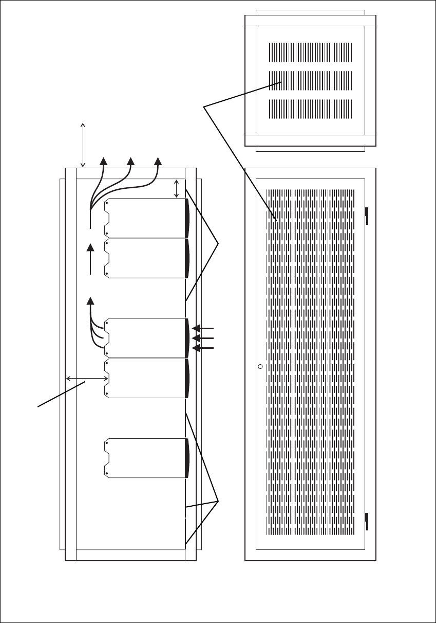
5.1.5 Cabinet and Rack Ventilation
The cooling airflow for the base station enters through the front panel and
exits at the rear of the subrack. For optimum thermal performance, the
heated air that has passed through a base station must not be allowed to re-
enter the air intakes on the front panel. Any space at the front of the cabinet
not occupied by equipment should be covered by a blanking panel. Refer
to Figure 5.1 on page 64.
To allow enough cooling airflow through a cabinet-mounted base station,
we recommend the following:
■an area of at least 23in2(150cm2) of unrestricted ventilation slots or
holes in front of the air intakes for the fans for each subrack; for
example, thirty 0.25x3.3in (6x85mm) slots will allow the
recommended airflow
■a vent in the top of the cabinet with an area of approximately 23in2
(150cm2) per subrack, or a similar area of ventilation per subrack at the
rear of the cabinet behind each subrack
■a 2U gap at the top of the cabinet.
Notice The ventilation opening must be unrestricted. If the slots or
holes are covered with a filter, mesh or grille, the open area must be
increased to allow the same airflow as an unrestricted opening.
The maximum ambient temperature entering the cabinet must not exceed
+140°F (+60°C).
If you are installing multiple subracks in a cabinet, ensure that there will be
enough cooling airflow through the cabinet after the equipment has been
installed. For example, the recommended maximum number of subracks in
a 38U cabinet is five, as shown in Figure 5.1 on page 64.
If the base station is installed in a rack or cabinet with other equipment with
different ventilation requirements, we recommend that the base station be
positioned below this equipment.
Auxiliary Extractor
Fans
The base station does not require auxiliary extractor fans mounted in the
top of the cabinet. If your cabinet is already fitted with fans, the following
procedures apply:
■if there are six or more 4.75in (12cm) fans, each capable of extracting
94.2 ft3 per minute (160m3 per hour), they must run continuously
■if there are fewer than six fans, you must remove them and ensure the
vent in the top of the cabinet has an area of approximately 23in2
(150cm2) per subrack.
If you have any other configuration, the performance of your system will
depend on how closely you comply with the base station airflow
requirements described above.
64 Installation TB9300 Installation and Operation Manual
© Tait Limited July 2012
Figure 5.1 Typical cabinet ventilation requirements
bventilation slots dairflow entry
cblanking panels eairflow exit path
8in
(20cm)
2U
≥7in
(≥17.5cm)
side view front view
top view
c
c
d
e
b
TB9300 Installation and Operation Manual Installation 65
© Tait Limited July 2012
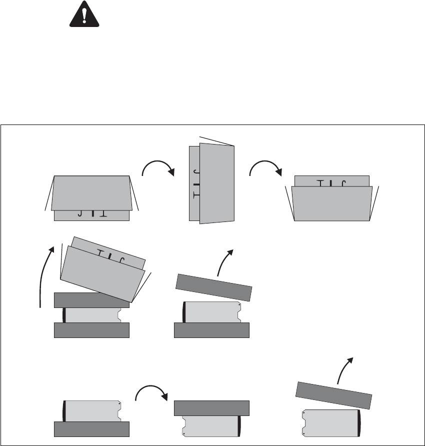
5.2 Unpacking and Moving the Subrack
The subrack is packed in a strong corrugated cardboard carton with top and
bottom foam cushions. To prevent personal injury and damage to the
equipment, we recommend that two people unpack and move the subrack.
To remove the subrack from the carton, follow the procedure illustrated in
Figure 5.2.
Caution A subrack complete with modules can weigh up to 62lb
(28kg), or up to 66lb (30kg) complete with packaging. We recommend
that you have another person help you unpack and move the equipment.
The TBAA03-16 carrying handles will make it easier to move the
equipment once it has been unpacked. If necessary, remove the modules
from the subrack before moving it (refer to “Replacing Modules” on
page 91). In all cases follow safe lifting practices.
1. Cut the tape securing the flaps at the top of the carton and fold them
flat against the sides b.
2. Rotate the carton carefully onto its side c and then onto its top d,
ensuring that none of the flaps is trapped underneath.
Figure 5.2 Unpacking the subrack
b
e
g
f
hi
cd
66 Installation TB9300 Installation and Operation Manual
© Tait Limited July 2012
3. Slide the carton upwards over the foam cushions and lift it away e.
Remove the cushion from the bottom of the subrack f.
4. Rotate the subrack and cushion carefully over the rear of the subrack
g so that it is the right way up with the cushion on top h. Remove
the cushion from the top of the subrack i.
Disposal of
Packaging
If you do not need to keep the packaging, we recommend that you recycle
it according to your local recycling methods. The foam cushions are CFC-
and HCFC-free and may be burnt in a suitable waste-to-energy combustion
facility, or compacted in landfill.

TB9300 Installation and Operation Manual Installation 67
© Tait Limited July 2012
5.3 Identifying the Equipment
You can identify the model and hardware configuration of the TB9300
modules by referring to the product code printed on labels at the rear of
each module. The meaning of each character in the product code is
explained in the tables below.
This explanation of product codes is not intended to suggest that any
combination of features is necessarily available in any one product.
Consult your regional Tait office for more information regarding the
availability of specific models and options.
Reciter Product
Codes
PA Product Codes
Product Code Description
T01-01103-XXXX Frequency Band and Sub-band
D = 148MHz to 174MHz (B3)
T01-01103-XXXX A = standard
T01-01103-XXXX A = default
T01-01103-XXXXA = default
Product Code Description
TBAXXXX-XXXX 8 = 50W
9 = 100W
TBAXXXX-XXXX 0 = default
TBAXXXX-XXXX Frequency Band and Sub-band
B1 = 136MHz to 174MHz
TBAXXXX-XXXX 0 = default
TBAXXXX-XXXX 0 = default
TBAXXXX-XXXX 0 = default
TBAXXXX-XXXX1 = default

68 Installation TB9300 Installation and Operation Manual
© Tait Limited July 2012
PMU Product
Codes Product Code Description
TBAXXXX-XXXX 3 = PMU
TBA3XXX-XXXX 0 = default
TBA3XXX-XXXX 0 = AC module not fitted
A = AC module fitted
TBA3XXX-XXXX 0 = DC module not fitted
1 = 12V DC module fitted
2 = 24V DC module fitted
4 = 48V DC module fitted
TBA3XXX-XXXX 0 = standby power supply card not fitted
1 = 12VDC standby power supply card fitted
2 = 24VDC standby power supply card fitted
4 = 48VDC standby power supply card fitted
TBA3XXX-XXXX 0 = auxiliary power supply board not fitted
1 = 12VDC auxiliary power supply board fitted
2 = 24VDC auxiliary power supply board fitted
4 = 48VDC auxiliary power supply board fitted
TBA3XXX-XXXX 0 = default
TBA3XXX-XXXX0 = default
TB9300 Installation and Operation Manual Installation 69
© Tait Limited July 2012
5.4 Initial Setting Up
Before putting the base station into service, you may want to carry out
some basic functional testing, configuration, and tuning (if required). This
section provides an overview of these procedures:
■checking that the base station powers up correctly
■checking the basic functionality of the base station by using the tests
available in the web interface
■customizing the configuration for the intended installation and
verifying that the configuration is correct
■changing the root password
■tuning the base station (if required).
5.4.1 Confirming Operation
Notice Make sure that the RF output is connected to a suitable atten-
uator or dummy load. Do not remove the load while the PA is transmit-
ting as this may damage the PA output stage.
Applying Power 1. Apply power by turning on the PMU.
2. Check that the base station powers up correctly:
■The front panel display will show “Please wait...” while the base
station starts up (this may take up to two minutes). When the
startup process is complete, the display will show the home
screen.
■The cooling fans in the front panel will run at full speed for a few
seconds, then run at low speed while the base station starts up,
and then assume standard operation. One or more fans may
operate, depending on the temperature of the modules.

70 Installation TB9300 Installation and Operation Manual
© Tait Limited July 2012
Functional Tests The following table provides an overview of the tests available using the
web interface. Refer to the Help for full details of these tests.
Test Notes Menu
receiver operation requires a suitable RF source Diagnose > RF Interface > Receiver
transmitter operation requires connection to the
network
Diagnose > RF Interface > Transmitter
ping checks the IP connection to
another device with an IP address
Diagnose > Connection > Network
NTP query checks if the NTP-based time
synchronization is working
PMU mains failure requires a DC backup supply Diagnose > Subsystems > PMU Control
Tests
fan operation checks the operation of each fan
individually
Diagnose > Subsystems > Fan Tests
TB9300 Installation and Operation Manual Installation 71
© Tait Limited July 2012
5.4.2 Customizing the Configuration
The following steps provide an overview of the process used to configure
the base station with the settings it needs. Refer to the Help for detailed
information.
1. Log in to the base station (refer to “Connecting Your PC to the Base
Station” on page 46 for more details).
2. Select Configure. The base station has many different settings that
can be configured before it is put into operation, such as:
■channel configurations
■alarm control and SNMP agent
■network interfaces
■quality of service
■CWID
■miscellaneous items such as minimum battery voltages, fan
control, NTP and package servers.
3. Make the changes needed in each form and click Save.
We recommend that you save the configuration to your PC or network.
First make a backup copy of the configuration (which is stored in the base
station as a file), then save this file to a folder on your PC or network. This
provides a backup which can be restored to the base station if the
configuration information becomes lost or corrupted.
72 Installation TB9300 Installation and Operation Manual
© Tait Limited July 2012
5.4.3 Changing the Root Password
The root password to the Linux operating system of the reciter is a possible
security risk. The equipment is delivered with a default password that is
well known. Knowledge of the password could be used to render the
equipment inoperable, for example by deleting files. If you are concerned
about the security risk that this poses, change the password. If Tait provides
support services, it may need to know the password.
Notice If you change the password and then lose it, the equipment
must be returned to Tait. Make sure that you store the password securely
and do not lose it.
To change the root password, follow these steps.
1. Log in from your PC to the base station using SSH client software
such as PuTTY. The username is “root” and the default password is
“k1w1”.
2. At the # prompt, enter the command “passwd”.
3. Follow the on-screen instructions.
4. Record the password in a secure location.
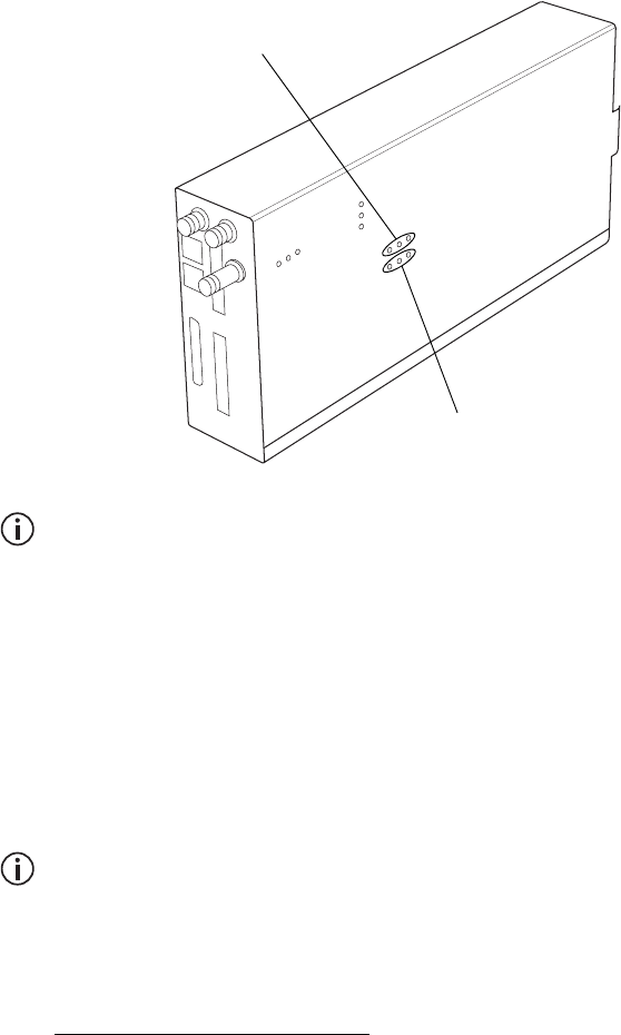
5.4.4 Tuning the Reciter
Before the base station is installed on site, you may need to tune the
receiver front end. The receiver front end requires tuning if the receive
frequency is shifted more than 2MHz away from the previously set
frequency, or the RSSI level of the new frequency is more than 1dB lower
than the RSSI level of the previously set frequency.
The receiver in the B3-band VHF reciter covers the 148 to 174MHz
frequency band. This is split into two sub-bands: 148 to 159MHz and
159 to 174MHz. Each sub-band has its own helical filter which is
electronically switched in or out of circuit depending on the frequency
programmed into the reciter. The bandwidth of these helical filters is
approximately ±1.5MHz.
To check the RSSI level and tune the receiver front end (if required), follow
these steps.
1. Log in to the reciter and select Monitor > Interfaces > RF Interface.
2. Feed a signal at the currently tuned receive frequency and at a level
of –80dBm into the reciter’s RF input. Check that the RSSI reading
on the RF Interface page is –80dBm ±1dB. Note this reading.
3. Set the reciter to the new receive frequency.
TB9300 Installation and Operation Manual Installation 73
© Tait Limited July 2012
4. Change the RF input signal to the new receive frequency at
–80dBm. Check that the RSSI reading is –80dBm ±1dB. If it is, the
receiver front end does not require tuning. If it is not, go to the next
step.
5. Using the Johanson tuning tool1, adjust the correct helical filter for
the new frequency (as shown below) to obtain a peak RSSI reading.
This reading should be within 1dB of the reading at the previous
frequency.
Adjust the center resonator of the filter first, followed by the two
outer resonators (in any order). Each resonator should require
approximately the same amount of adjustment when tuning.
A change in frequency of 5MHz requires approximately one turn of the
tuning slug. If tuning to a lower frequency, adjust the slug in (clock-
wise); for a higher frequency, adjust the slug out (counterclockwise).
6. Change the RF input signal and the reciter’s receive frequency to
0.5MHz above and below the required frequency and check that the
RSSI reading does not drop by more than 0.5dB from the reading at
the required frequency.
7. Recalibrate the RSSI at the new frequency (Calibrate > Reciter >
RSSI).
If you wish to confirm the accuracy of the tuning procedure, carry out a
sensitivity measurement at the new frequency.
1. Included in the TBA0ST2 tool kit. Also available separately as part num-
ber 937-00013-00.
148 to 159MHz
159 to 174MHz
74 Installation TB9300 Installation and Operation Manual
© Tait Limited July 2012
5.5 Installing the Base Station on Site
5.5.1 Base Stations for Trunked Systems
When installing base stations that are part of a trunked system, it is very
important to observe good site engineering rules. This is especially true
when the channels are combined into a single antenna, particularly if the
receivers and transmitters also share the antenna, as in a duplexed system.
If at all possible, the RF planner should avoid frequency plans in which the
Rx to Tx spacing is an exact multiple of the trunked channel spacing, thus
forcing Tx intermodulation products to fall outside the Rx channels.
Cables and antennas should be of high quality construction. Solid shield
heliax type cables are best, but if braided shield cables must be used for
short distances, their braids must be silver-plated. Isolators should be used
at all transmitter outputs.
When the outputs of more than one transmitter are combined, their voltages
add, and the resulting peak envelope power is not simply the sum of their
powers, but is equal to the power of one of them multiplied by the square
of the number of sources. Cables, components, and hardware must be rated
to withstand the peak envelope power.
During the commissioning process, all transmitters should be activated
together using a diagnostic test tone, while the receiver RSSI is monitored.
There should be no perceptible increase in RSSI while the transmitters are
active.
5.5.2 Equipment Required
It is beyond the scope of this manual to list every piece of equipment that
an installation technician should carry. However, the following tools are
specifically required for installing the base station:
■Pozidriv PZ3 screwdriver for the M6 screws used in the DC input
terminals on the PMU; M6 (0.25in) screws are also used to secure the
subrack to the cabinet in factory-assembled systems
■Pozidriv PZ2 screwdriver for the M4 screws used to secure the module
retaining clamps, and for the fasteners used to secure the front panel to
the subrack
■8mm AF spanner for the SMA connectors, and the subrack ground
connector.
You can also obtain the TBA0ST2 tool kit from your regional Tait office.
It contains the basic tools needed to install, tune, and service the base
station.
TB9300 Installation and Operation Manual Installation 75
© Tait Limited July 2012
5.5.3 Mounting the Subrack
Caution A subrack complete with modules can weigh up to 62lb
(28kg), or up to 66lb (30kg) complete with packaging. We recommend
that you have another person help you unpack and move the equipment.
The TBAA03-16 carrying handles will make it easier to move the
equipment once it has been unpacked. If necessary, remove the modules
from the subrack before moving it (refer to “Replacing Modules” on
page 91). In all cases follow safe lifting practices.
1. Remove the front panel, as described in “Preliminary Disassembly”
on page 93.
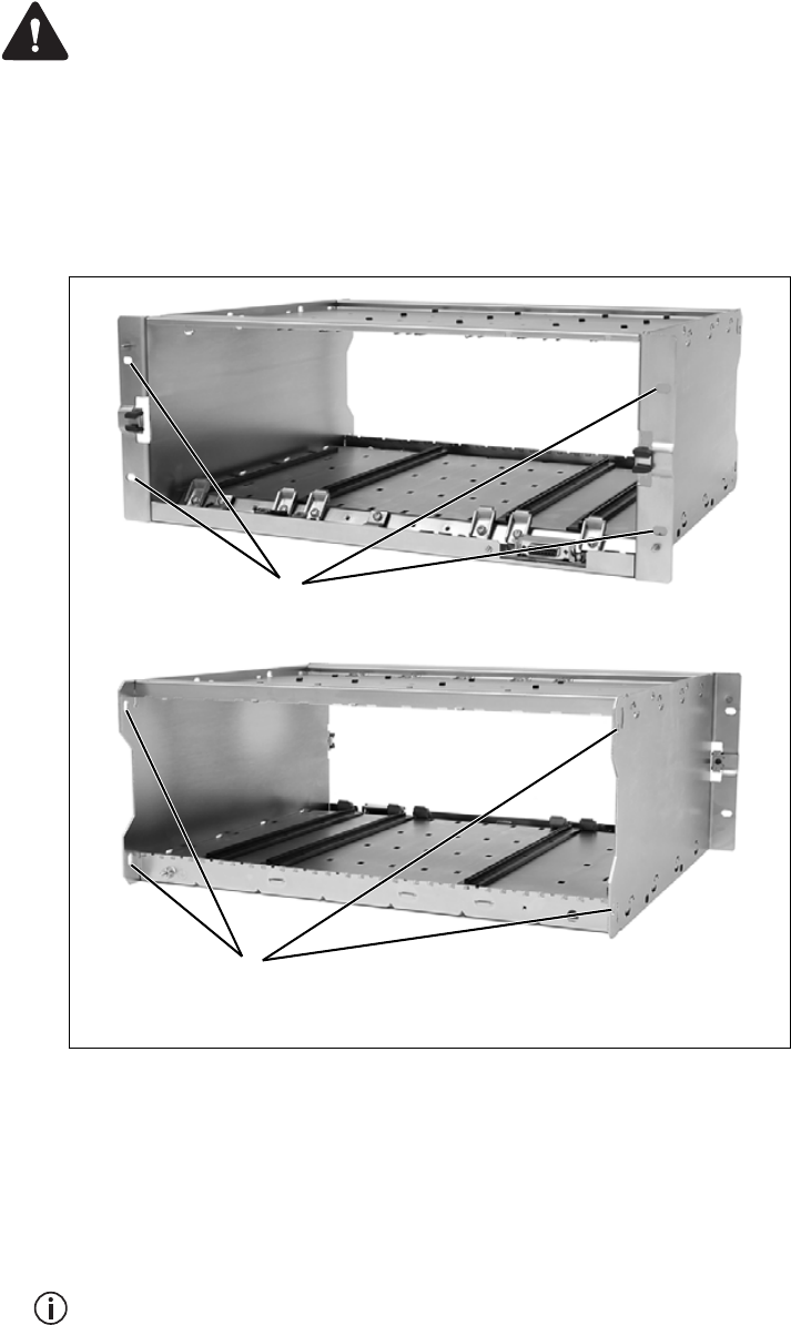
2. Fit the subrack into the cabinet or rack and secure it firmly with an
M6 (0.25in) screw, flat and spring washer in each of the four main
mounting holes b, as shown in Figure 5.3.
If you need extra mounting security, additional mounting holes c are
provided at the rear of the subrack for auxiliary support brackets.
Figure 5.3 Subrack mounting points
bmain mounting holes - front cauxiliary mounting holes - rear
front view
rear view
b
c
76 Installation TB9300 Installation and Operation Manual
© Tait Limited July 2012
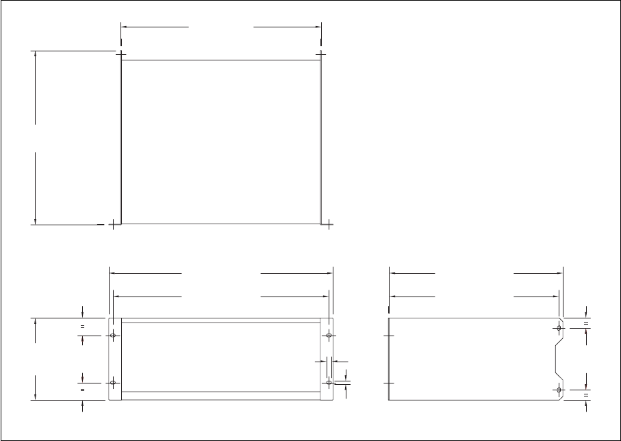
Figure 5.4 below gives the dimensions of the subrack and its mounting
holes.
Figure 5.4 Subrack dimensions
5.25 in
(133.4 mm)
4 in
(101.6 mm)
6.96 in
(176.8 mm)
14.8 in
(375.5 mm)
19 in (482.6 mm)
17 in (432 mm)
18.3 in (465.1 mm)
0.26 in
(6.6 mm)
0.42 in
(10.6 mm)
14.7 in (373.5 mm)
14.37 in (365 mm)
TB9300 Installation and Operation Manual Installation 77
© Tait Limited July 2012
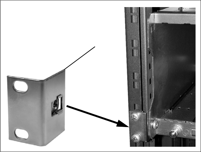
Auxiliary Support
Bracket
TBAA03-13 auxiliary support brackets can be fitted to the rear of the
subrack to provide additional mounting security. Figure 5.5 shows a
standard TBAA03-13 bracket b fitted in a typical Tait cabinet c. If you
are not using the Tait cabinet, you may have to make your own brackets to
suit your installation.
Notice You must fit the auxiliary support brackets if you intend to
transport a cabinet fitted with a fully built-up base station.
We also recommend that you fit the brackets under the following
conditions:
■when the installation is in an area prone to earthquakes
■when third party equipment is installed hard up underneath the base
station subrack.
General Cabling We recommend that you try to route all cables to and from the base station
along the side of the cabinet so the cooling airflow is not restricted.
Figure 5.5 Auxiliary support bracket
c
b
78 Installation TB9300 Installation and Operation Manual
© Tait Limited July 2012
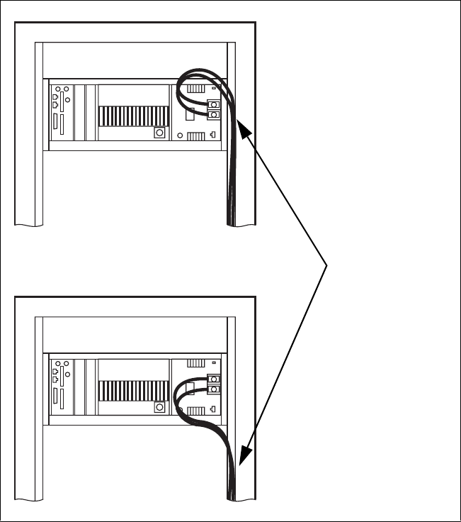
DC Power Cabling DC power cables should be well supported so that the terminals on the
PMU and on the ends of the cables do not have to support the full weight
of the cables.
Figure 5.6 shows two recommended methods of securing these cables to
prevent straining either set of terminals.
We recommend that you fit the supplied covers to the DC terminals to
protect against accidental shorts.
Figure 5.6 DC power cabling
secure the cables to the
cabinet to support their
weight
TB9300 Installation and Operation Manual Installation 79
© Tait Limited July 2012
5.6 Connecting Up the Base Station
This section provides information relevant to the task of connecting up the
various inputs and outputs of the base station.
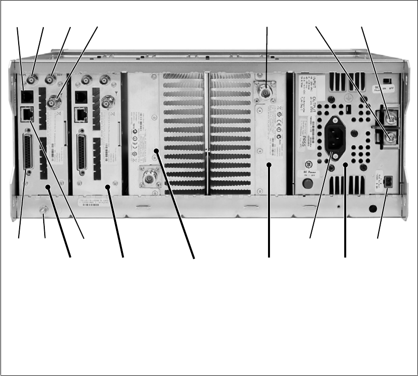
5.6.1 Connection Overview
The connections at the rear of a dual 50W base station are identified in
Figure 5.7. External connections are all located at the rear of the subrack.
Figure 5.7 50W base station inputs and outputs
bserial RS-232 connectorah+VDC input
c1PPS input iauxiliary DC output
dexternal reference frequency input jAC mains input
eRF input 1) Ethernet interface connector
fRF output 1! subrack ground connector
g–VDC input 1@ system interface connector
a. Factory use only.
PA 1
Reciter 1 PMU
bcde fgh
ij1)1!
1@
PA 2
Reciter 2
80 Installation TB9300 Installation and Operation Manual
© Tait Limited July 2012
5.6.2 Connecting AC Power
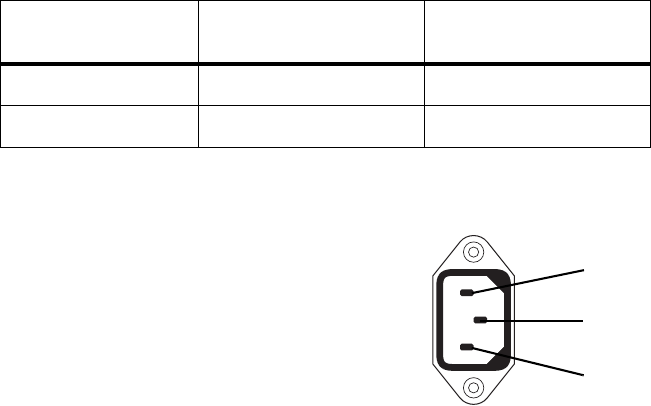
The PMU is designed to accept a mains input of 88 to 264VAC at 45 to
65Hz. A standard 3-wire grounded socket outlet must be used to supply the
AC power. The socket outlet must be installed near the equipment and must
be easily accessible. This outlet should be connected to an AC power
supply capable of providing at least 600W. The requirements of two typical
AC supplies are given in the following table.
Your base station should come supplied
with a power supply cord to connect the
male IEC connector on the PMU to the
local AC supply. The pins of the IEC
connector on the PMU are identified at
right.
Nominal Supply Current Requirementa
a. The actual current consumption of the base station will be lower than these re-
quirements (refer to the Specifications Manual for more information).
Circuit Breaker/Fuse
Ratinga
115VAC 8A 10A
230VAC 4A 6A
ground
rear view
neutral
phase
TB9300 Installation and Operation Manual Installation 81
© Tait Limited July 2012
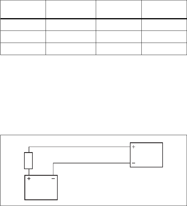
5.6.3 Connecting DC Power
The PMU is designed to accept a nominal 12VDC, 24VDC or 48VDC
input (depending on the model) with negative or positive ground. There is
a minimum DC startup threshold to prevent damaging a battery which has
little capacity left.
You must connect the DC supply from the battery to the PMU via a fuse or
DC-rated circuit breaker with a contact separation of 3mm, and with the
appropriate rating, as shown in the table below. The DC input leads should
be of a suitable gauge to ensure less than 0.2V drop at maximum load over
the required length of lead.
Terminate and insulate the DC input leads to protect them from
accidentally shorting to the subrack if the PMU is removed before the leads
are disconnected. Protective covers for the DC terminals are supplied with
each PMU.
We recommend a screw torque of 18–20lbf·in (2–2.25N·m).
Nominal Supply
Voltage
Input Voltage
Range
Circuit Breaker/
Fuse Ratinga
a. The actual current consumption of the base station will be lower than these re-
quirements (refer to the Specifications Manual for more information).
Recommended
Wire Gaugeb
b. For a length of 5ft to 6.5ft (1.5m to 2m) (typical).
12VDC 10VDC to 16.8VDC 60A 2AWG / 35mm2
24VDC 20VDC to 33.6VDC 30A 5AWG / 16mm2
48VDC 40VDC to 60VDC 15A 8AWG / 8mm2
Figure 5.8 Recommended DC power connection
Battery
Circuit Breaker
or Fuse
PMU

82 Installation TB9300 Installation and Operation Manual
© Tait Limited July 2012
5.6.4 Connecting the Auxiliary DC Power Output
The PMU can provide an auxiliary DC output when it is fitted with the
auxiliary power supply board. This board is available with an output of
13.65VDC, 27.3VDC, or 54.6VDC (depending on the model), and is
current limited to 3A, 1.5A or 750mA respectively. This power supply is
permanently on as soon as the base station has finished powering up, and
is available on the auxiliary output connector on the rear panel.
You can connect multiple auxiliary power supply boards in parallel for
redundancy purposes, or to provide an output greater than 40W. Although
no active current sharing is used, auxiliary boards connected in parallel will
current-share before reaching their power limit. The failure (or switching
off) of one auxiliary board will not load any other paralleled auxiliary
boards in the circuit.
Auxiliary DC Power
Output Cabling
Network elements are supplied with a connector, as shown in Figure 5.9.
You can use this to connect the PMU’s auxiliary DC power output to
another device (refer to “PMU Auxiliary DC Output” on page 105 for the
pin allocations).
Contact your regional Tait office for details on the full range of wiring kits
available.
Figure 5.9 Auxiliary DC power connector
Phoenix MVSTBR2.5HC/2-ST/5.08 female
TB9300 Installation and Operation Manual Installation 83
© Tait Limited July 2012
5.6.5 Connecting RF
Notice Do not remove the load from the PA while it is transmitting
as this may damage the PA output stage.
The RF input to the base station is via the marked BNC connector on the
rear panel of the reciter. The RF output is via the N-type connector on the
rear panel of the PA (refer to Figure 5.7 on page 79).
Cables and antennas should be of high quality construction. Solid shield
heliax type cables are best, but if braided shield cables must be used for
short distances, their braids must be silver-plated.
Recommendations
for Installing the PA
We recommend the following installation procedures, which should protect
the PA from damage under all but the most extreme operating conditions.
1. Do not connect the PA directly to the antenna. Fit an isolator or
duplexer between the PA and the load. Fit the isolator as close as pos-
sible to the RF output connector on the PA. Do not connect any
switching equipment between the isolator and the PA, unless the
switch cannot operate while there is RF present (i.e. the base station
is transmitting).
2. Fit a surge suppressor to the antenna cabling where it enters the
building.
3. Inspect all cables and equipment connected to the base station for
defects.
Ice on the antenna, or a broken antenna, is unlikely to cause damage to the
PA.
Explanation The circuit design of the PA protects the circuitry from high VSWR. This
makes it difficult to damage the RF power device by keying the PA into a
mismatched load, or if the load deteriorates over even a short period of time
(milliseconds).
However, it is possible to damage the device if all the following conditions
happen at the same time:
■there is a step change in the PA load (for example, the load is removed)
■the PA is transmitting
■the feed line loss between the PA and the mismatch is <1dB.
The effect of such conditions is variable: some devices will not be
destroyed, and some may fail after repeated load interruptions.
84 Installation TB9300 Installation and Operation Manual
© Tait Limited July 2012
5.6.6 Connecting an External Frequency Reference
An external reference frequency is not normally required for B3 band.
However, an external reference can be used with a TB9300 when you need
to maximize the range of the base station. The external reference frequency
can be 10MHz or 12.8MHz, with an input level of 300mVpp to 5Vpp. The
stability of this reference should be better than 50 parts per billion. The
reciter automatically detects the frequency of the external reference and
configures itself accordingly.
If an external reference is required, enable the external reference “Absent”
alarm (Configure > Alarms > Control).
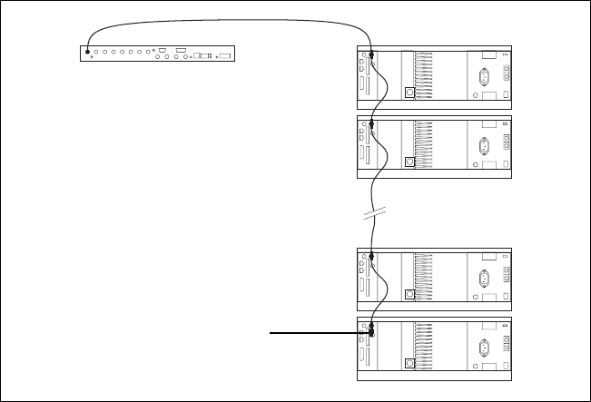
Use a 50Ω coaxial cable (RG58 or RG223) to connect the external
reference to the base station’s external reference frequency input. You can
daisy-chain up to eight base stations using F-junctions. The maximum
overall cable length is 30m. Terminate the last connection with a 50Ω load.
Figure 5.10 Daisy-chaining an external frequency reference input
50Ω termination
maximum of eight base
station loads on one
frequency reference output
maximum overall cable
length is 30m
TB9300 Installation and Operation Manual Installation 85
© Tait Limited July 2012
5.6.7 Ethernet Connection
The RJ-45 socket on the reciter’s rear panel provides the 10BASE-T or
100BASE-T Ethernet connection to the other devices in the network. Use
Cat-5 cable to connect this socket to the TaitNet DMR Network via a router
or switch.
If necessary, refer to “Ethernet Connector” on page 105 for a list of
Ethernet connection pin allocations.
86 Installation TB9300 Installation and Operation Manual
© Tait Limited July 2012
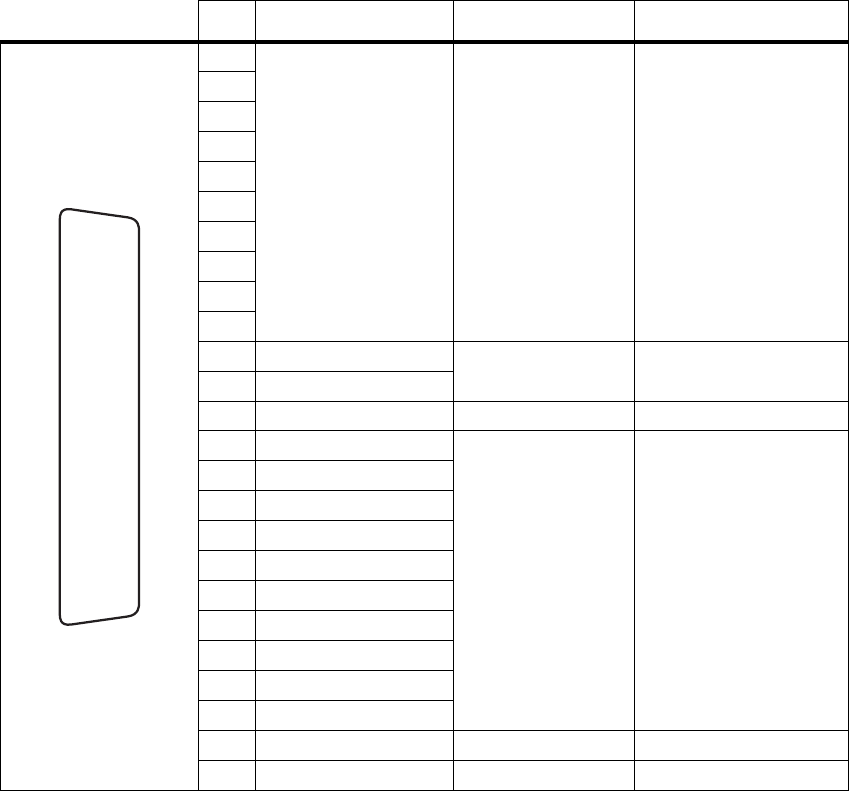
5.6.8 Connecting General Purpose Inputs and Outputs
The base station has a number of general purpose inputs and outputs. These
are connected via the 25-way D-range on the rear panel.
The pin allocations for the D-range connector are given in the following
table. Not all pins are used in this release of the base station.
Pin Signal Name Signal Type Notes
1
not used reserved for future use
2
3
4
5
6
7
8
9
10
11 digital in 1 input 5V TTL logic
active low
12 digital in 2
13 +5.2VDC output power output maximum current 200mA
14 digital in 3
input 5V TTL logic
active low
15 digital in 4
16 digital in 5
17 digital in 6
18 digital in 7
19 digital in 8
20 digital in 9
21 digital in 10
22 digital in 11
23 digital in 11
24 not used reserved for future use
25 ground ground
external view
B
C
D
E
F
G
H
I
J
1)
1!
1@
1#
1$
1%
1^
1&
1*
1(
2)
2!
2@
2#
2$
2%