Tait TBCH0X Receive Only Base Station with Ethernet Port User Manual TB9400 Installation and Operation Manual

Tait Limited Receive Only Base Station with Ethernet Port TB9400 Installation and Operation Manual

Exhibit D Users Manual per 2 1033 b3
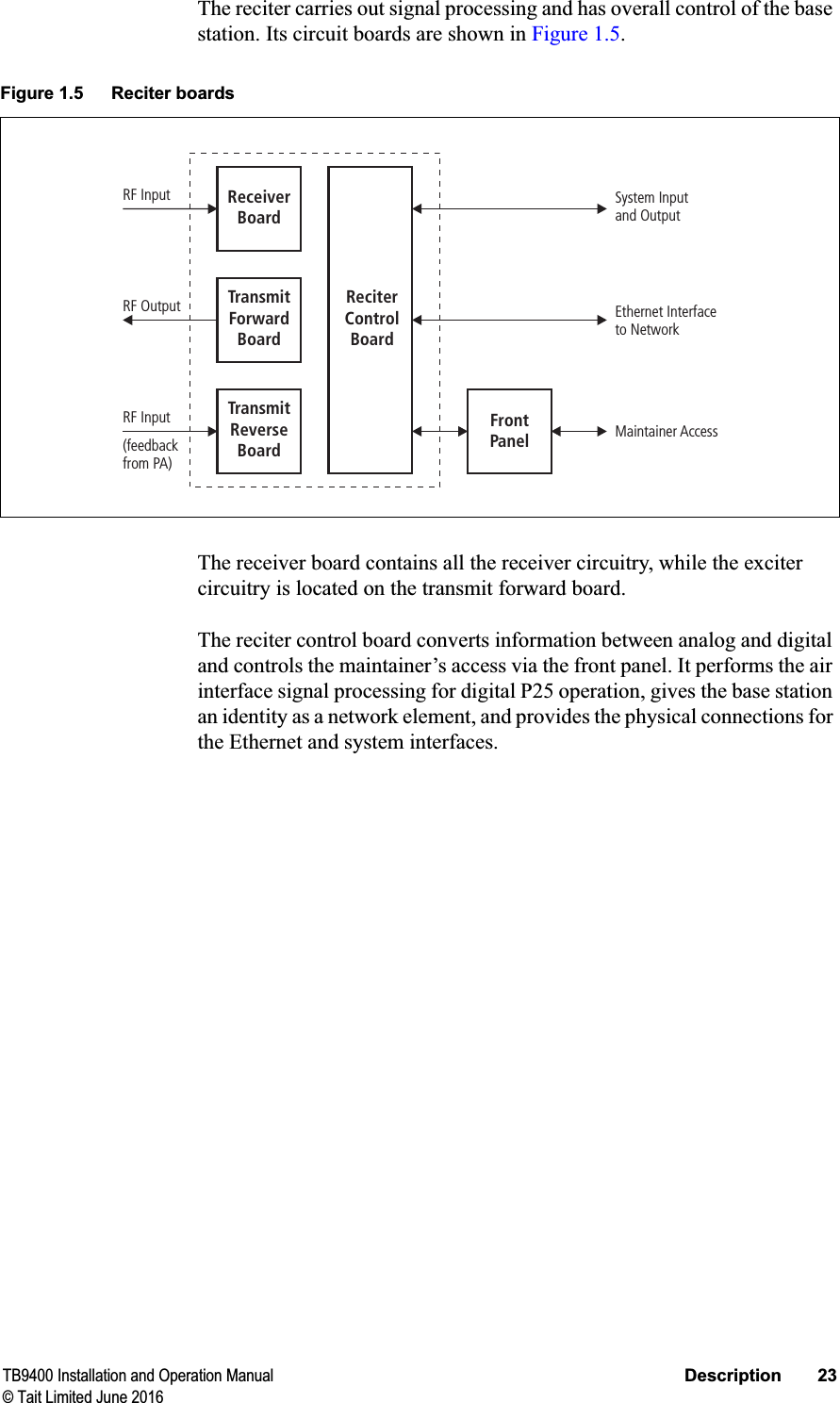
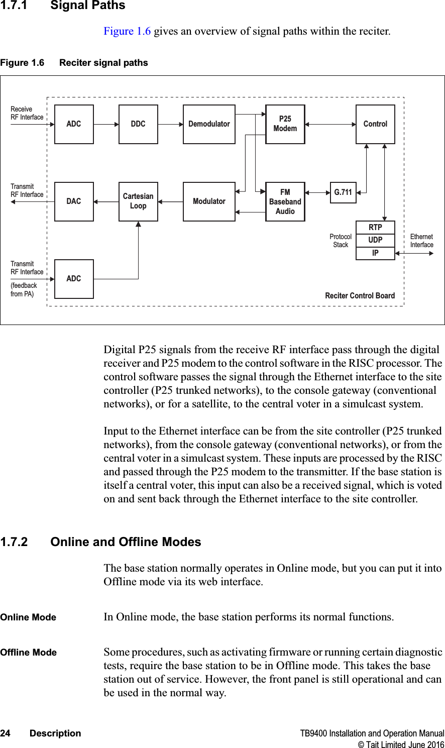
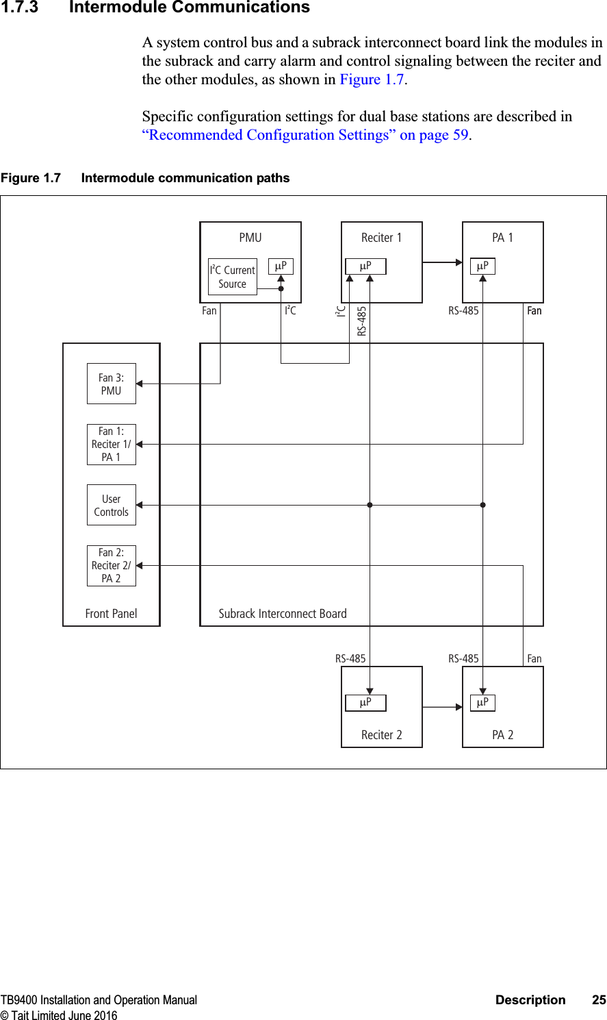
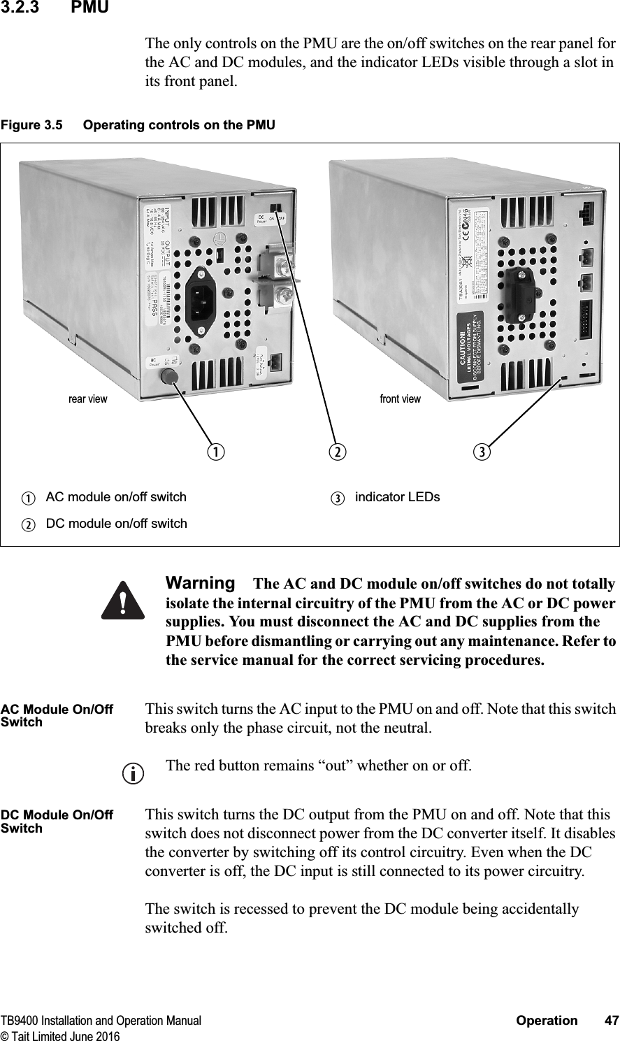
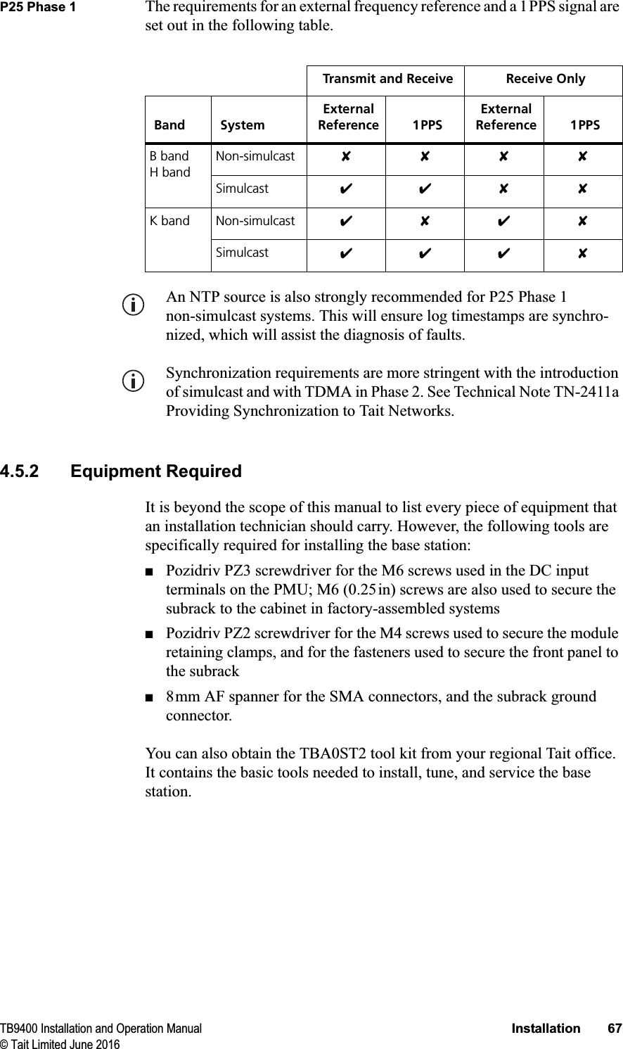
TB9400 Base Station/RepeaterInstallation and Operation ManualMBC-00001-13 · Issue 13 · June 2016
2TB9400 Installation and Operation Manual© Tait Limited June 2016Contact InformationTait CommunicationsCorporate Head OfficeTait LimitedP.O. Box 1645ChristchurchNew ZealandFor the address and telephone number of regional offices, refer to our website: www.taitradio.comCopyright and TrademarksAll information contained in this document is the property of Tait Limited. All rights reserved. This document may not, in whole or in part, be copied, photocopied, reproduced, translated, stored, or reduced to any electronic medium or machine-readable form, without prior written permission from Tait Limited.The word TAIT and the TAIT logo are trademarks of Tait Limited.All trade names referenced are the service mark, trademark or registered trademark of the respective manufacturers.DisclaimerThere are no warranties extended or granted by this document. Tait Limited accepts no responsibility for damage arising from use of the information contained in the document or of the equipment and software it describes. It is the responsibility of the user to ensure that use of such information, equipment and software complies with the laws, rules and regulations of the applicable jurisdictions.Enquiries and CommentsIf you have any enquiries regarding this document, or any comments, suggestions and notifications of errors, please contact your regional Tait office.Updates of Manual and EquipmentIn the interests of improving the performance, reliability or servicing of the equipment, Tait Limited reserves the right to update the equipment or this document or both without prior notice.Intellectual Property RightsThis product may be protected by one or more patents or designs of Tait Limited together with their international equivalents, pending patent or design applications, and registered trade marks: NZ409837, NZ409838, NZ415277, NZ415278, NZ508806, NZ519742/NZ516280, NZ524369, NZ524378, NZ524509, NZ530819, NZ534475, NZ547713, NZ569985, NZ577009, NZ579051, NZ579364, NZ584534, NZ586889, NZ592624, NZ593888, NZ600346, NZ610563, NZ615954, NZ629167, NZ630718, NZ700387, NZ700908, NZ708662, NZ710766, NZ711325, NZ714188, AU2004216984, AU2015215962, AU339127, AU339391, AU2015904806, EU000915475-0001, EU000915475-0002, UK1518031.8, US 8301682, US13/542147, US14/032876, US14/495334, US14/725922, US14/818712, US14/832420, US62/128101, US62/128129, US640974, US640977, US698339, US702666, US7758996, US7937661, US8902804, US9107231.This product may also be made under license under one or more of the following U.S. Patents: 5,146,497, 5,148,482, 5,164,986, 5,185,795, 5,185,796, 5,271,017, 5,377,229 and 5,502,767.The AMBE+2™ voice coding Technology embodied in this product is protected by intellectual property rights including patent rights, copyrights and trade secrets of Digital Voice Systems, Inc. This voice coding Technology is licensed solely for use within this Communications Equipment. The user of this Technology is explicitly prohibited from attempting to decompile, reverse engineer, or disassemble the Object Code, or in any other way convert the Object Code into a human-readable form. Protected by U.S. Patents 5,870,405, 5,826,222, 5,754,974, 5,701,390, 5,715,365, 5,649,050, 5,630,011, 5,581,656, 5,517,511, 5,491,772, 5,247,579, 5,226,084 and 5,195,166.This product includes software developed by the OpenSSL Project for use in the OpenSSL Toolkit (http://www.openssl.org/).Environmental ResponsibilitiesTait Limited is an environmentally responsible company which supports waste minimization, material recovery and restrictions in the use of hazardous materials. The European Union’s Waste Electrical and Electronic Equipment (WEEE) Directive requires that this product be disposed of separately from the general waste stream when its service life is over. For more information about how to dispose of your unwanted Tait product, visit the Tait WEEE website at www.taitradio.com/weee. Please be environmentally responsible and dispose through the original supplier, or contact Tait Limited.Tait Limited also complies with the Restriction of the Use of Certain Hazardous Substances in Electrical and Electronic Equipment (RoHS) Directive in the European Union.In China, we comply with the Measures for Administration of the Pollution Control of Electronic Information Products. We will comply with environmental requirements in other markets as they are introduced.
TB9400 Installation and Operation Manual 3© Tait Limited June 2016ContentsPreface . . . . . . . . . . . . . . . . . . . . . . . . . . . . . . . . . . . . . . . . . . . . . . . . . . . . . . . . . . . . . . . . . . . . .  7Scope of Manual. . . . . . . . . . . . . . . . . . . . . . . . . . . . . . . . . . . . . . . . . . . . . . . . . . . . . . . .  7Document Conventions  . . . . . . . . . . . . . . . . . . . . . . . . . . . . . . . . . . . . . . . . . . . . . . . . . .  7Associated Documentation. . . . . . . . . . . . . . . . . . . . . . . . . . . . . . . . . . . . . . . . . . . . . . . .  81 Description . . . . . . . . . . . . . . . . . . . . . . . . . . . . . . . . . . . . . . . . . . . . . . . . . . . . . . . . . . . . .  101.1 Features  . . . . . . . . . . . . . . . . . . . . . . . . . . . . . . . . . . . . . . . . . . . . . . . . . . . . . . . . . .111.2 Modules . . . . . . . . . . . . . . . . . . . . . . . . . . . . . . . . . . . . . . . . . . . . . . . . . . . . . . . . .  121.3 Mechanical Assembly  . . . . . . . . . . . . . . . . . . . . . . . . . . . . . . . . . . . . . . . . . . . . . .  151.4 Frequency Bands and Sub-bands . . . . . . . . . . . . . . . . . . . . . . . . . . . . . . . . . . . . . .  181.5 Applications . . . . . . . . . . . . . . . . . . . . . . . . . . . . . . . . . . . . . . . . . . . . . . . . . . . . . .  191.6 Licenses . . . . . . . . . . . . . . . . . . . . . . . . . . . . . . . . . . . . . . . . . . . . . . . . . . . . . . . . .  201.7 Theory of Operation. . . . . . . . . . . . . . . . . . . . . . . . . . . . . . . . . . . . . . . . . . . . . . . .  221.7.1 Signal Paths . . . . . . . . . . . . . . . . . . . . . . . . . . . . . . . . . . . . . . . . . . . . . .  241.7.2 Online and Offline Modes . . . . . . . . . . . . . . . . . . . . . . . . . . . . . . . . . . .  241.7.3 Intermodule Communications . . . . . . . . . . . . . . . . . . . . . . . . . . . . . . . .  251.7.4 Power Management and Distribution  . . . . . . . . . . . . . . . . . . . . . . . . . .  261.7.5 PMU Operation on DC Input. . . . . . . . . . . . . . . . . . . . . . . . . . . . . . . . .  281.7.6 Front Panel Fans  . . . . . . . . . . . . . . . . . . . . . . . . . . . . . . . . . . . . . . . . . .  312 General Safety and Regulatory Information  . . . . . . . . . . . . . . . . . . . . . . . . . . . . . . . . .  322.1 Personal Safety. . . . . . . . . . . . . . . . . . . . . . . . . . . . . . . . . . . . . . . . . . . . . . . . . . . .  332.1.1 Unpacking and Moving the Equipment. . . . . . . . . . . . . . . . . . . . . . . . .  332.1.2 Lethal Voltages  . . . . . . . . . . . . . . . . . . . . . . . . . . . . . . . . . . . . . . . . . . .  332.1.3 AC Power Connection . . . . . . . . . . . . . . . . . . . . . . . . . . . . . . . . . . . . . .  342.1.4 Explosive Environments . . . . . . . . . . . . . . . . . . . . . . . . . . . . . . . . . . . .  342.1.5 High Temperatures. . . . . . . . . . . . . . . . . . . . . . . . . . . . . . . . . . . . . . . . .  342.1.6 LED Safety (EN60825-1) . . . . . . . . . . . . . . . . . . . . . . . . . . . . . . . . . . .  342.1.7 Proximity to RF Transmissions / A proximité des émissions RF . . . . .  352.2 Equipment Safety . . . . . . . . . . . . . . . . . . . . . . . . . . . . . . . . . . . . . . . . . . . . . . . . . .  362.2.1 Installation and Servicing Personnel . . . . . . . . . . . . . . . . . . . . . . . . . . .  362.2.2 Preventing Damage to the PA . . . . . . . . . . . . . . . . . . . . . . . . . . . . . . . .  362.2.3 ESD Precautions  . . . . . . . . . . . . . . . . . . . . . . . . . . . . . . . . . . . . . . . . . .  362.2.4 Anti-tampering Devices. . . . . . . . . . . . . . . . . . . . . . . . . . . . . . . . . . . . .  372.3 Environmental Conditions . . . . . . . . . . . . . . . . . . . . . . . . . . . . . . . . . . . . . . . . . . .  372.3.1 Operating Temperature Range. . . . . . . . . . . . . . . . . . . . . . . . . . . . . . . .  372.3.2 Humidity . . . . . . . . . . . . . . . . . . . . . . . . . . . . . . . . . . . . . . . . . . . . . . . .  372.3.3 Dust and Dirt . . . . . . . . . . . . . . . . . . . . . . . . . . . . . . . . . . . . . . . . . . . . .  372.4 Regulatory Information . . . . . . . . . . . . . . . . . . . . . . . . . . . . . . . . . . . . . . . . . . . . .  382.4.1 Distress Frequencies  . . . . . . . . . . . . . . . . . . . . . . . . . . . . . . . . . . . . . . .  382.4.2 Compliance Standards . . . . . . . . . . . . . . . . . . . . . . . . . . . . . . . . . . . . . .  38
4TB9400 Installation and Operation Manual© Tait Limited June 20162.4.3 FCC Compliance . . . . . . . . . . . . . . . . . . . . . . . . . . . . . . . . . . . . . . . . . .  382.4.4 Unauthorized Modifications  . . . . . . . . . . . . . . . . . . . . . . . . . . . . . . . . .  383 Operation . . . . . . . . . . . . . . . . . . . . . . . . . . . . . . . . . . . . . . . . . . . . . . . . . . . . . . . . . . . . . .  393.1 Front Panel . . . . . . . . . . . . . . . . . . . . . . . . . . . . . . . . . . . . . . . . . . . . . . . . . . . . . . .  403.2 Module Indicator LEDs and Switches . . . . . . . . . . . . . . . . . . . . . . . . . . . . . . . . . .  443.2.1 Reciter and Receiver  . . . . . . . . . . . . . . . . . . . . . . . . . . . . . . . . . . . . . . .  443.2.2 PA. . . . . . . . . . . . . . . . . . . . . . . . . . . . . . . . . . . . . . . . . . . . . . . . . . . . . .  463.2.3 PMU. . . . . . . . . . . . . . . . . . . . . . . . . . . . . . . . . . . . . . . . . . . . . . . . . . . .  474 Installation . . . . . . . . . . . . . . . . . . . . . . . . . . . . . . . . . . . . . . . . . . . . . . . . . . . . . . . . . . . . .  494.1 Before You Begin . . . . . . . . . . . . . . . . . . . . . . . . . . . . . . . . . . . . . . . . . . . . . . . . . .  504.1.1 Equipment Security . . . . . . . . . . . . . . . . . . . . . . . . . . . . . . . . . . . . . . . .  504.1.2 Grounding and Lightning Protection . . . . . . . . . . . . . . . . . . . . . . . . . . .  504.1.3 Equipment Ventilation . . . . . . . . . . . . . . . . . . . . . . . . . . . . . . . . . . . . . .  504.1.4 Ambient Temperature Sensor. . . . . . . . . . . . . . . . . . . . . . . . . . . . . . . . .  504.1.5 Cabinet and Rack Ventilation. . . . . . . . . . . . . . . . . . . . . . . . . . . . . . . . .  514.2 Unpacking and Moving the Subrack  . . . . . . . . . . . . . . . . . . . . . . . . . . . . . . . . . . .  534.3 Identifying the Equipment . . . . . . . . . . . . . . . . . . . . . . . . . . . . . . . . . . . . . . . . . . .  554.4 Initial Setting Up  . . . . . . . . . . . . . . . . . . . . . . . . . . . . . . . . . . . . . . . . . . . . . . . . . .  574.4.1 Confirming Operation  . . . . . . . . . . . . . . . . . . . . . . . . . . . . . . . . . . . . . .  574.4.2 Customizing the Configuration . . . . . . . . . . . . . . . . . . . . . . . . . . . . . . .  594.4.3 Recommended Configuration Settings  . . . . . . . . . . . . . . . . . . . . . . . . .  594.4.4 Restricted Port Numbers  . . . . . . . . . . . . . . . . . . . . . . . . . . . . . . . . . . . .  604.4.5 Changing the Root Password . . . . . . . . . . . . . . . . . . . . . . . . . . . . . . . . .  604.4.6 Tuning the Reciter and Receiver . . . . . . . . . . . . . . . . . . . . . . . . . . . . . .  614.5 Installing the Base Station on Site . . . . . . . . . . . . . . . . . . . . . . . . . . . . . . . . . . . . .  664.5.1 General Installation Advice . . . . . . . . . . . . . . . . . . . . . . . . . . . . . . . . . .  664.5.2 Equipment Required  . . . . . . . . . . . . . . . . . . . . . . . . . . . . . . . . . . . . . . .  674.5.3 Mounting the Subrack . . . . . . . . . . . . . . . . . . . . . . . . . . . . . . . . . . . . . .  684.6 Connecting Up the Base Station. . . . . . . . . . . . . . . . . . . . . . . . . . . . . . . . . . . . . . .  724.6.1 Connection Overview  . . . . . . . . . . . . . . . . . . . . . . . . . . . . . . . . . . . . . .  724.6.2 Connecting AC Power . . . . . . . . . . . . . . . . . . . . . . . . . . . . . . . . . . . . . .  734.6.3 Connecting DC Power . . . . . . . . . . . . . . . . . . . . . . . . . . . . . . . . . . . . . .  744.6.4 Connecting the Auxiliary DC Power Output . . . . . . . . . . . . . . . . . . . . .  754.6.5 Connecting RF . . . . . . . . . . . . . . . . . . . . . . . . . . . . . . . . . . . . . . . . . . . .  764.6.6 Connecting an External Frequency Reference. . . . . . . . . . . . . . . . . . . .  774.6.7 Connecting a 1PPS Source  . . . . . . . . . . . . . . . . . . . . . . . . . . . . . . . . . .  784.6.8 Ethernet Connection. . . . . . . . . . . . . . . . . . . . . . . . . . . . . . . . . . . . . . . .  784.6.9 Connecting General Purpose Inputs and Outputs  . . . . . . . . . . . . . . . . .  805 Working with Base Stations from Your PC . . . . . . . . . . . . . . . . . . . . . . . . . . . . . . . . . . .  815.1 PC Recommendations  . . . . . . . . . . . . . . . . . . . . . . . . . . . . . . . . . . . . . . . . . . . . . .  825.2 Connecting Your PC to the Base Station . . . . . . . . . . . . . . . . . . . . . . . . . . . . . . . .  825.2.1 Logging In . . . . . . . . . . . . . . . . . . . . . . . . . . . . . . . . . . . . . . . . . . . . . . .  835.2.2 Setting the IP Address . . . . . . . . . . . . . . . . . . . . . . . . . . . . . . . . . . . . . .  845.2.3 Security Certificates. . . . . . . . . . . . . . . . . . . . . . . . . . . . . . . . . . . . . . . .  85
TB9400 Installation and Operation Manual 5© Tait Limited June 20165.2.4 Connecting a Networked PC to a Base Station . . . . . . . . . . . . . . . . . . .  865.2.5 Troubleshooting Connection Problems . . . . . . . . . . . . . . . . . . . . . . . . .  885.2.6 Finding a Lost or Forgotten IP Address  . . . . . . . . . . . . . . . . . . . . . . . .  885.2.7 Setting Up Authentication . . . . . . . . . . . . . . . . . . . . . . . . . . . . . . . . . . .  895.3 Working with the Web Interface  . . . . . . . . . . . . . . . . . . . . . . . . . . . . . . . . . . . . . .  905.3.1 Monitoring Operation  . . . . . . . . . . . . . . . . . . . . . . . . . . . . . . . . . . . . . .  915.3.2 Viewing Configuration Settings  . . . . . . . . . . . . . . . . . . . . . . . . . . . . . .  935.3.3 Viewing the Base Station and Network Identity . . . . . . . . . . . . . . . . . .  965.4 Basic Tasks. . . . . . . . . . . . . . . . . . . . . . . . . . . . . . . . . . . . . . . . . . . . . . . . . . . . . . .  975.4.1 User Settings . . . . . . . . . . . . . . . . . . . . . . . . . . . . . . . . . . . . . . . . . . . . .  975.4.2 Taking the Base Station Offline. . . . . . . . . . . . . . . . . . . . . . . . . . . . . . .  975.4.3 Troubleshooting Alarms  . . . . . . . . . . . . . . . . . . . . . . . . . . . . . . . . . . . .  975.4.4 Working with Configuration Files . . . . . . . . . . . . . . . . . . . . . . . . . . . . .  985.4.5 Configuring Single Base Stations . . . . . . . . . . . . . . . . . . . . . . . . . . . . .  985.4.6 Configuring Receive-Only Base Stations . . . . . . . . . . . . . . . . . . . . . . .  995.4.7 Configuring Base Stations in a Channel Group. . . . . . . . . . . . . . . . . . .  995.4.8 Setting Up Custom Alarms . . . . . . . . . . . . . . . . . . . . . . . . . . . . . . . . .  1005.4.9 Disabling the Front Panel Keypad. . . . . . . . . . . . . . . . . . . . . . . . . . . .  1005.4.10 Preparing to Download Firmware . . . . . . . . . . . . . . . . . . . . . . . . . . . .  1005.4.11 Checking for Interference on a Receive Channel . . . . . . . . . . . . . . . .  1026 Maintenance. . . . . . . . . . . . . . . . . . . . . . . . . . . . . . . . . . . . . . . . . . . . . . . . . . . . . . . . . . .  1037 Troubleshooting . . . . . . . . . . . . . . . . . . . . . . . . . . . . . . . . . . . . . . . . . . . . . . . . . . . . . . . . 1058 Replacing Modules  . . . . . . . . . . . . . . . . . . . . . . . . . . . . . . . . . . . . . . . . . . . . . . . . . . . . .  1068.1 Saving the Base Station’s Configuration . . . . . . . . . . . . . . . . . . . . . . . . . . . . . . .  1078.2 Preliminary Disassembly . . . . . . . . . . . . . . . . . . . . . . . . . . . . . . . . . . . . . . . . . . .  1088.3 Replacing a Reciter  . . . . . . . . . . . . . . . . . . . . . . . . . . . . . . . . . . . . . . . . . . . . . . . .1108.4 Replacing a Power Amplifier. . . . . . . . . . . . . . . . . . . . . . . . . . . . . . . . . . . . . . . . .1128.5 Replacing a Power Management Unit . . . . . . . . . . . . . . . . . . . . . . . . . . . . . . . . . .1148.6 Replacing the Module Guide Rails  . . . . . . . . . . . . . . . . . . . . . . . . . . . . . . . . . . . .1158.7 Replacing the Subrack Interconnect Board . . . . . . . . . . . . . . . . . . . . . . . . . . . . . .1168.8 Final Reassembly . . . . . . . . . . . . . . . . . . . . . . . . . . . . . . . . . . . . . . . . . . . . . . . . . .117Appendix A – Interface Pin Allocations . . . . . . . . . . . . . . . . . . . . . . . . . . . . . . . . . . . . . . . . .118System Interface Connector . . . . . . . . . . . . . . . . . . . . . . . . . . . . . . . . . . . . . . . . . . . . . .118Ethernet Connector. . . . . . . . . . . . . . . . . . . . . . . . . . . . . . . . . . . . . . . . . . . . . . . . . . . . .118PMU Auxiliary DC Output  . . . . . . . . . . . . . . . . . . . . . . . . . . . . . . . . . . . . . . . . . . . . . .118Appendix B – Inter-Module Connections . . . . . . . . . . . . . . . . . . . . . . . . . . . . . . . . . . . . . . . .119Dual 50W Base Station  . . . . . . . . . . . . . . . . . . . . . . . . . . . . . . . . . . . . . . . . . . . . . . . . .119Single 50W Base Station . . . . . . . . . . . . . . . . . . . . . . . . . . . . . . . . . . . . . . . . . . . . . . .  120100W Base Station. . . . . . . . . . . . . . . . . . . . . . . . . . . . . . . . . . . . . . . . . . . . . . . . . . . .  121
6TB9400 Installation and Operation Manual© Tait Limited June 2016Receive-only Base Station . . . . . . . . . . . . . . . . . . . . . . . . . . . . . . . . . . . . . . . . . . . . . .  122Appendix C – Identifying Front Panels  . . . . . . . . . . . . . . . . . . . . . . . . . . . . . . . . . . . . . . . .  123Glossary . . . . . . . . . . . . . . . . . . . . . . . . . . . . . . . . . . . . . . . . . . . . . . . . . . . . . . . . . . . . . . . . . .  124Tait Software License Agreement  . . . . . . . . . . . . . . . . . . . . . . . . . . . . . . . . . . . . . . . . . . . . .  136Directive 1999/5/EC Declaration of Conformity  . . . . . . . . . . . . . . . . . . . . . . . . . . . . . . . . .  140
TB9400 Installation and Operation Manual Preface 7© Tait Limited June 2016PrefaceScope of ManualThis manual provides information on installing and operating the TB9400 base station. It is intended for use by experienced technicians familiar with installing and operating base station equipment. It also includes configuration, maintenance and troubleshooting information. Except where stated otherwise, the information in this manual generally applies to both standard and receive-only base stations and reciters. When “reciter” is referred to, this generally applies also to the receiver (receive-only reciter). References to power amplifiers (PAs) and trans-mitting obviously do not apply to receive-only equipment.In the following, unless mentioned specifically, this manual will use the term “base station” to mean both base station and repeater.Document ConventionsThe TB9400 base station has a web interface with an accordion menu on the left side of the screen. “Configure > Base Station > Channels” means click Configure in the top-level menu, then in the expanded Configure menu click Base Station, and finally click on the Channels tab on that page.Within this manual, four types of alerts may be given to the reader. The following paragraphs illustrate each type of alert and its associated symbol.Warning This alert is used when there is a hazardous situation which, if not avoided, could result in death or serious injury.Caution This alert is used when there is a hazardous situation which, if not avoided, could result in minor or moderate injury.Notice This alert is used to highlight information that is required to ensure procedures are performed correctly. Incorrectly performed pro-cedures could result in equipment damage or malfunction.This icon is used to draw your attention to information that may improve your understanding of the equipment or procedure.
8 Preface TB9400 Installation and Operation Manual© Tait Limited June 2016Associated DocumentationThe following associated documentation for this product is available on the Tait support website.■TB9400 Specifications Manual (MBC-00002-xx)■TN9400 P25 Trunked Network Maintenance Manual (MNC-00001-xx)■TaitNet P25 Trunked Networks with TB9400 Base Stations System Manual (MBA-00064-xx)■TaitNet Analog Conventional Networks with TB9400 Base Stations System Manual (MND-00001-xx)■Safety and Compliance Information (MBA-00012-xx)The characters xx represent the issue number of the documentation.Technical notes are published from time to time to describe applications for Tait products, to provide technical details not included in manuals, and to offer solutions for any problems that arise. Technical notes are available in PDF format from the Tait support website. For more information contact your regional Tait office.
TB9400 Installation and Operation Manual Preface 9© Tait Limited June 2016Issue Publication Date Description1 May 2012 First release2 November 2012 General updates for version 1.15 release.Information added on compliance standards, marshalling duration, firmware download procedure, and restricted port numbers.3 May 2013 General updates for version 1.20 release and the B3-band base station.Front end tuning procedure added.4 August 2013 General updates for version 1.25 release and the H-band base station.Information added for dual 50W and receive-only base stations.5 November 2013 General updates for version 1.30 release.Minor updates for receive-only base station.Directive 1999/5/EC Declaration of Conformity added.6 April 2014 General updates for version 1.35 release.PMU fan thresholds updated. Information added on proximity to RF transmissions, AAA Authentication, and checking for interference on a receive channel.7 August 2014 General updates for version 1.40 release. Information added for K4-band receive-only base station, and P25 Phase 2 operation.8 November 2014 General updates for version 1.45 release. Information added for P25 Phase 2 licenses.9 March 2015 General updates for version 2.00 release. Information added on P25 Phase 2 operation.10 July 2015 General updates for version 2.05 release. Information added for receive-only base stations and receiver modules, feature licenses, uploading security certificates, and external frequency reference stability requirements.11 November 2015 General updates for version 2.10 release. Information added for analog base stations. Feature license names updated.12 March 2016 General updates for version 2.15 release.Clarification of repeater vs. base station for K band in Brazil added.13 June 2016 General updates for version 2.20 release.Added MPT feature, P25 Conventional features, modified licence table, updated and annotated images and general updates.
10 Description TB9400 Installation and Operation Manual© Tait Limited June 20161 DescriptionThe Tait TB9400 base station is a robust state-of-the-art digital fixed station that combines Tait’s proven strengths in reliability, high performance and modular design with software-based configurability and operation, digital signal processing and voice-over-IP technology.The base station operates Project 25 trunked or trunked simulcast radio network. It is capable of either P25 Phase 1 FDMA operation, or 6.25kHz equivalent P25 Phase 2 TDMA operation The TB9400 can also operate in an analog conventional simulcast or non-simulcast multi-site network.The base station combines industry-leading digital voice quality with rugged design specifications and intuitive user interfaces. These products have been designed to meet the demanding needs of the public safety and public service sectors.The ability of the base station to link stations using standard Internet Protocol communications, and to add features through software options ensures that P25 systems designed with the TB9400 are scalable in both size and functionality.Its Ethernet interface provides built-in network connectivity, allowing the TB9400 to join with other TB9400 base stations to form a channel group. This network supports voice-over-IP and remote management of all base stations via a web browser.
TB9400 Installation and Operation Manual Description 11© Tait Limited June 20161.1 FeaturesThe following are some of the features of the base station:■Fully compliant with the Project 25 Common Air Interface. Can therefore interoperate with any similarly compliant radios.■P25 Phase 1 operation (C4FM and CQPSK modulation).■P25 Phase 2 operation (H-DQPSK modulation).■Analog conventional repeater operation.■Analog conventional simulcast operation on an IP backbone requiring no audio calibration or training.■Linear power amplifier allows operation with Linear Simulcast Modulation (LSM). ■Integrated built-in voting facility. No external voter is needed.■P25 simulcast conventional repeater / line connected base station.■Can be completely managed remotely from a PC running a web browser: configuration, alarm monitoring, fault diagnosis, feature and firmware upgrades. Alarms can also be reported via SNMP traps, allowing integration with an SNMP-based network management system.■An integrated wiring solution is provided for the system control bus and DC power connections to each module in the subrack.■Reciters (receiver/exciter modules) can be replaced without affecting the operation of other reciters in the same subrack.■Rugged construction with generous heatsinks and fan-forced cooling for continuous operation from –22°F to +140°F (–30°C to +60°C).
12 Description TB9400 Installation and Operation Manual© Tait Limited June 20161.2 ModulesThe base station consists of a subrack with up to two transmit/receive channels, or up to four receive-only channels. Receive-only base stations are currently available for operation only on B3 band (148MHz to 174MHz) and K4 band (762MHz to 870MHz)1.The single PMU (power management unit) supplies and manages power to the whole subrack (refer to “Theory of Operation” on page 22). One reciter and one PA (power amplifier) are needed for each transmit/receive channel. The PA is not required for a receive-only base station. There is also a front panel with user controls and fans. The modules are interconnected at the front of the subrack. External connections to the modules are located at the rear.Modules come in different variants depending, for example, on the RF band or the supply voltage. Each module is inserted into the 4U subrack from the front and is secured at the front with a metal clamp. Both clamp and module are easily removed for rapid module replacement. The modules are secured laterally with plastic guides that clip into the top and bottom of the subrack. These guides can be easily repositioned to change the configuration of a subrack. The heavier modules are also secured laterally by metal tabs at the rear of the subrack.The following provides a brief description of the available modules.Subrack The 4U subrack is made of passivated steel and is designed to fit into a standard 19 inch rack or cabinet. The subrack is fitted with an interconnect board that connects the system control bus and power to the modules and front panel. The position of a module in the subrack is defined by the socket on the subrack interconnect board to which the module is connected by the system control bus. 1. Refer to “Frequency Bands and Sub-bands” on page 18.
TB9400 Installation and Operation Manual Description 13© Tait Limited June 2016Front Panel The front panel is mounted onto the subrack with two quick-release fasteners. It incorporates the indicator LEDs, four-line LCD display, user controls, ambient temperature sensor and cooling fans.The indicator LEDS allow some monitoring of the operational status of the base station. The user controls and display allow the technician to configure the IP address of each module. Refer to “Front Panel” on page 40for more information.The microphone input and speaker are not used in this release of the TB9400.Reciter The reciter module comprises the receiver, exciter and digital control circuitry. The reciter provides the Ethernet interface and system inputs and outputs. Receiver modules (receive-only reciters) are not fitted with the transmit circuitry or front panel SMA connectors, and are physically unable to transmit.reciter receiver
14 Description TB9400 Installation and Operation Manual© Tait Limited June 2016Power Amplifier The PA amplifies the RF output from the reciter and is available in 50W and 100W models.The 50W model mounts vertically in the subrack, while the 100W model mounts horizontally as it has a wider heatsink. The 100W PA is also fitted with an airflow duct.Both models are designed to operate on the 28VDC output provided by the PMU. PAs are not required in a receive-only base station.Power Management UnitThe PMU provides the 28VDC power supply for the modules in the subrack. It can operate on 120/230VAC 50/60Hz nominal, and 12, 24 or 48VDC nominal. The input voltage can be AC, DC, or both AC and DC, depending on the model. The PMU also has an auxiliary DC output of 13.65VDC, 27.3VDC, or 54.6VDC, depending on the model.50W PA 100W PAAC and DC PMU shown
TB9400 Installation and Operation Manual Description 15© Tait Limited June 20161.3 Mechanical AssemblyThis section illustrates the main mechanical components of the base station.Figure 1.1 below shows the configuration for a typical dual 50W base station. The subrack has six slots, numbered from right to left as viewed from the front of the subrack. The PMU occupies slots 5 and 6, with the reciter and PA pairs to the right of it in slots 1 to 4. Each PA is mounted vertically with its heatsink facing its associated reciter. The PMU and each reciter/PA pair have their own cooling fans.The front panel can be easily removed from the subrack by undoing two quick-release fasteners. Refer to “Replacing Modules” on page 106 for more details..Figure 1.1 Mechanical assembly - dual 50W base station with front panelbfront panel ireciter 1csubrack jmodule retaining clampdPMU 1) subrack interconnect boardePA 2 1! plastic guide railfreciter 2 1@ subrack interconnect board retaining clampgcable retaining clip 1# front panel fastenerhPA 1bcdefghij1)1!1@1#
16 Description TB9400 Installation and Operation Manual© Tait Limited June 2016Figure 1.2 below shows the configuration for a typical single 50W base station. The PMU again occupies slots 5 and 6, with the reciter in slot 1 and PA in slot 2. The PA is mounted vertically with its heatsink facing the reciter. The PMU and the reciter/PA pair have their own cooling fans.Figure 1.2 Mechanical assembly - single 50W base stationbPMU dreciterc50W PA esubrackbcde
TB9400 Installation and Operation Manual Description 17© Tait Limited June 2016Figure 1.3 below shows the configuration for a typical 100 W base station. The PMU occupies slots 5 and 6, with the PA directly beside it in slots 3 and 4. The reciter occupies slot 1. Unlike the 50W PAs, the 100W PA is mounted horizontally with the heatsink facing upwards. It is also fitted with an airflow duct to channel the airflow from the cooling fan through the heatsink fins.Figure 1.3 Mechanical assembly - single 100W base stationbPMU erecitercPA fsubrackdairflow duct gcable retaining clipbcdefg
18 Description TB9400 Installation and Operation Manual© Tait Limited June 20161.4 Frequency Bands and Sub-bandsMuch of the circuitry in the base station is common to all frequency bands, and is therefore covered by a single description in this manual. In some cases the descriptions refer to specific bands or sub-bands, and these are identified with the letters listed in the following table.In Brazil, for K band, the TB9400 is considered to be configured as a base station with retransmission of receive frequencies.Frequency Identification Frequency Band and Sub-band 50W 100W Receive-onlyB band B3 = 148MHz to 174MHz ✓✓ ✓H band H1 = 400MHz to 440MHzH2 = 440MHz to 480MHz ✓✓K band K4 = 762MHz to 870MHza✓✓ ✓a. The actual frequency coverage in this band is:Transmit: 762MHz to 776MHz, and 850MHz to 870MHzReceive: 792MHz to 824MHz
TB9400 Installation and Operation Manual Description 19© Tait Limited June 20161.5 ApplicationsThe TB9400 operates in P25 trunked networks (Phase 1 or Phase 2), P25 conventional networks and analog conventional networks. It operates as a stand-alone repeater/base station, or as part of a channel group, providing receiver voting and simulcast transmission. All air interfaces and system types support simulcast operation.In P25 Phase 2 operation, a single TB9400 base station can provide two traffic channels, since each radio frequency (physical channel) provides two logical channels (timeslots). However, it can provide only one control channel, since control channels are still P25 Phase 1.In a trunked simulcast network, the transmitters in the channel group are synchronized and transmit simultaneously on the same frequency. Each transmitter needs a highly accurate 1PPS pulse and an external frequency reference, so that it can time transmissions with the required accuracy. Also required is an NTP source that is derived from the same source as the 1PPS signal. This will ensure a common timestamp in logs across all units in the system. An external frequency reference, along with an NTP source and 1PPS signal derived from the same GPS source, are also essential for all reciters for P25 Phase 2 operation.In a P25 conventional network, the TB9400 operates as a single or wide area conventional repeater, with receiver voting and optional simulcast. Dispatch connection is via the Tait P25 Console Gateway, supporting conversion between P25 and analog consoles with MDC1200 signalling.In an analog conventional network it can operate as a repeater with CTCSS1 subaudible signaling.The base station can also operate as part of an analog conventional simulcast network. It is fully IP-connected and requires no training. It also features an integral voter (thus requiring no external voter), and CTCSS subaudible signaling.The base station can be provided as a receive-only variant in systems that need sites to enhance the receive coverage. The receiver module in a receive-only base station is physically unable to transmit.The base station can be configured for Shared Channel operation, to detect interference on the uplink, as long as the site controller is compatible.For more information on these applications, refer to the Help and appropriate Tait System Manual.1. Private Line (PL).
20 Description TB9400 Installation and Operation Manual© Tait Limited June 20161.6 LicensesSome operational functions of the base station are controlled by licenses. These functions will not work unless you purchase the appropriate feature license and enable the feature set controlled by that license. The feature sets currently available are listed below.Analog Air Interface(TBAS041 - Default Licence)A base station with this license can operate as a repeater in an analog conventional network.P25 Common Air Interface(TBAS050)Allows the base station to go into Online mode. Base stations are always provided with this license.P25 Trunking Operation(TBAS056)Allows the base station to participate in a trunking system. Without this feature, the base station cannot provide a control or a status connection to a trunking site controller and it cannot function as a control or traffic channel.Central Voter(TBAS061)P25 and analog. This feature allows a base station to act as a central voter.Simulcast(TBAS062)This feature is required in base stations that have transmitters and belong to a P25 Phase 1 simulcast or analog simulcast network1. It is also required in the central voter of a simulcast channel.2Linear Simulcast Modulation(TBAS065)P25 only. Allows the base station to transmit using the LSM modulation scheme1. This scheme allows increased site separation in simulcast networks. Also requires the Simulcast license (TBAS062).P25 Trunking Failsoft(TBAS063)Allows trunked channels that become isolated from a site controller to perform simple conventional operation and to interface to a digital dispatch system. If a trunked channel consists of several base stations in a channel group, only the central voter (normally the master) needs this license. It is then able to become the failsoft repeater for that channel group. P25 Phase 2 Trunking(TBAS066)This feature allows the base station to operate in trunking mode using two-slot TDMA as defined by the P25 Phase 2 standards. 1. Not needed for receive-only base stations.2. The central voter in a simulcast channel needs the respective Phase 1 or Phase 2 simulcast license. Normally, a transceiver member of a simulcast channel will have a simulcast license, so this constraint should not be an issue.
TB9400 Installation and Operation Manual Description 21© Tait Limited June 2016P25 Phase 2 Simulcast(TBAS069)This feature is required in base stations that have transmitters and belong to a P25 Phase 2 simulcast network1. It is also required in the central voter of a P25 Phase 2 simulcast channel2. Also requires the P25 Phase 2 Trunking (TBAS066) and Simulcast (TBAS062) licenses. Tait also recommends adding the Linear Simulcast Modulation (TBAS065) license as it provides improved RF performance.IP Networking Satellite(TBAS071)P25 Phase 1 and analog. This feature allows a base station to be part of a channel group without requiring the Central Voter (TBAS061) license.Table 1.1 Licenses and applicabilityLicence Name Air Interface System TypeTBAS041 Analog Air Interface Analog ConventionalTBAS061 Central Voter P25 Phase 1 & 2 Trunked, ConventionalTBAS071 IP Networking Satellite P25 Phase 1 & 2 Trunked, ConventionalTBAS062 Simulcast P25 Phase 1 & 2 Trunked, ConventionalTBAS050 P25 Common Air Interface P25 Phase 1 & 2 Trunked, ConventionalTBAS065 Linear Simulcast Modulation P25 Phase 1 & 2 Trunked, ConventionalTBAS056 P25 Trunking Operation P25 Phase 1 & 2 TrunkedTBAS063 P25 Trunking Failsoft P25 Phase 1 & 2 TrunkedTBAS066 P25 Phase 2 Trunking P25 Phase 1 & 2 TrunkedTBAS069 P25 Phase 2 Simulcast P25 Phase 2 Trunked
22 Description TB9400 Installation and Operation Manual© Tait Limited June 20161.7 Theory of OperationThe reciter receives RF signals from its RF input and sends RF from its RF output to the PA, along with a PA key signal. The PA sends an RF feedback signal to the reciter for linearization and power control purposes. The reciter also receives signals from, and sends signals to, the system interface, the Ethernet interface, and the front panel (see Figure 1.4).A system control bus interconnects the modules and carries alarm and control signaling between the reciter and the other modules (refer to “Intermodule Communications” on page 25 for more details). The Ethernet interface carries voice over IP and also allows maintainer access via a web browser. Figure 1.4 Base station high-level diagramReciterPMU PARF ToAntennaRF FromAntenna 1PPSExternalReferenceFrequencyAC InputDC Input28VDCSystem Control BusRF+PAKeyRF FeedbackSystem Inputand OutputEthernet Interfaceto NetworkFrontPanelA receive-only base station has a receiver instead of a reciter, and does not have a PA.
TB9400 Installation and Operation Manual Description 23© Tait Limited June 2016The reciter carries out signal processing and has overall control of the base station. Its circuit boards are shown in Figure 1.5.The receiver board contains all the receiver circuitry, while the exciter circuitry is located on the transmit forward board.The reciter control board converts information between analog and digital and controls the maintainer’s access via the front panel. It performs the air interface signal processing for digital P25 operation, gives the base station an identity as a network element, and provides the physical connections for the Ethernet and system interfaces.Figure 1.5 Reciter boardsRF InputRF Input(feedbackfrom PA)RF OutputReceiverBoardTransmitForwardBoardTransmitReverseBoardFrontPanelReciterControlBoardMaintainer AccessSystem Inputand OutputEthernet Interfaceto Network
24 Description TB9400 Installation and Operation Manual© Tait Limited June 20161.7.1 Signal PathsFigure 1.6 gives an overview of signal paths within the reciter. Digital P25 signals from the receive RF interface pass through the digital receiver and P25 modem to the control software in the RISC processor. The control software passes the signal through the Ethernet interface to the site controller (P25 trunked networks), to the console gateway (conventional networks), or for a satellite, to the central voter in a simulcast system.Input to the Ethernet interface can be from the site controller (P25 trunked networks), from the console gateway (conventional networks), or from the central voter in a simulcast system. These inputs are processed by the RISC and passed through the P25 modem to the transmitter. If the base station is itself a central voter, this input can also be a received signal, which is voted on and sent back through the Ethernet interface to the site controller.1.7.2 Online and Offline ModesThe base station normally operates in Online mode, but you can put it into Offline mode via its web interface.Online Mode In Online mode, the base station performs its normal functions. Offline Mode Some procedures, such as activating firmware or running certain diagnostic tests, require the base station to be in Offline mode. This takes the base station out of service. However, the front panel is still operational and can be used in the normal way. Figure 1.6 Reciter signal pathsModulatorDemodulator P25ModemFMBasebandAudioG.711ControlADC DDCDACRTPUDPIPTransmitRF InterfaceReceiveRF InterfaceEthernetInterfaceProtocolStackReciter Control BoardCartesianLoopADCTransmitRF Interface(feedbackfrom PA)
TB9400 Installation and Operation Manual Description 25© Tait Limited June 20161.7.3 Intermodule CommunicationsA system control bus and a subrack interconnect board link the modules in the subrack and carry alarm and control signaling between the reciter and the other modules, as shown in Figure 1.7.Specific configuration settings for dual base stations are described in “Recommended Configuration Settings” on page 59.Figure 1.7 Intermodule communication pathsFanIC2RS-485RS-485IC2FanFanPA 1mPSubrack Interconnect BoardReciter 1mPFront PanelFan 3:PMUFan 1:Reciter 1/PA 1Fan 2:Reciter 2/PA 2UserControlsPMUmPI C CurrentSource2RS-485RS-485 FanPA 2mPReciter 2mP
26 Description TB9400 Installation and Operation Manual© Tait Limited June 20161.7.4 Power Management and DistributionThe PMU manages the supply of power to ensure uninterrupted operation of the base station. A range of parameters is monitored and these can trigger alarms that are sent to the reciter. Alarms can be monitored via the web interface and reported via SNMP traps; they are also recorded in the reciter’s internal log file.AC to DC ChangeoverWhen the PMU has an AC and a DC module, the base station can be powered by either the AC (mains) or the DC (battery) supply. The base station will default to the AC supply if both supplies are provided. If the AC supply becomes unavailable, a seamless changeover from the AC to DC supply takes place, providing that the battery voltage is above the configured minimum startup voltage. You can use a web browser to check whether the base station is running on battery or mains power.DC Operation When the base station is running off the DC supply and the battery voltage falls below the configured minimum, the base station will enter battery protection mode to protect the battery and base station equipment. The standby power supply card maintains the power to the PMU microprocessor, while the rest of the PMU is shut down. When the battery voltage rises to the configured startup setting, power is resumed to the DC supply. Refer to “PMU Operation on DC Input” on page 28 for more detailed information.Auxiliary Power ControlThe output from the auxiliary power supply board can be used to power other site equipment. The maximum output is 40W.Distribution Figure 1.8 shows how power is distributed to modules in the subrack. The 28VDC output from the PMU is fed directly to the PA in a single base station, or directly to PA 1 in a dual base station, and to the other modules via the subrack interconnect board. Power to the reciters and front panel is current-limited by self-resetting fuses on the subrack board.The AC converter has a series switch which breaks the phase input to the converter. The DC input, however, has much higher current ratings. Its switch does not disconnect power from the DC converter itself, but disables the converter by switching off its control circuitry.The outputs from both the AC and DC high power converters are added together and fed to the modules via the high-current outputs. The auxiliary output is also tapped off this summed output.
TB9400 Installation and Operation Manual Description 27© Tait Limited June 2016Figure 1.8 Subrack power distributionReceiver 1DC AC28VAux. DC 28VPMUPA ReciterSubrackBoardFrontPanelDC AC28VAux. DC 28VPMUPA 1 PA 2 Reciter 1SubrackBoardReciter 2 FrontPanelDC ACAux. DC 28VPMUReceiver 3SubrackBoardReceiver 4Receiver 2 FrontPanelSingleDualReceive-only
28 Description TB9400 Installation and Operation Manual© Tait Limited June 20161.7.5 PMU Operation on DC InputThe operation of the PMU on DC input is controlled by three sets of parameters:■user-programmable alarms■user-programmable startup and shutdown limits■battery protection limitsThe voltage range for each of these parameters is provided in Table 1.2 on page 29.Figure 1.9 on page 30 illustrates how these parameters interact, and how they control the operation of the PMU over a range of DC input voltages.Alarms User-programmable alarms can be set for low or high battery voltage (Configure > Alarms > Thresholds). The alarms will be triggered when the set voltage levels are reached. These limits are subject to the tolerances of the battery protection circuitry, as stated in “Battery Protection (Fail-safe) Limits” in Table 1.2.Startup and Shutdown LimitsThe user-programmable startup and shutdown limits allow for adjustable startup and shutdown voltages (Configure > Base Station > Miscellaneous). These limits can be adjusted for different numbers of battery cells, or for the particular requirements of the base station operation. Once the limits are reached, the PMU will shut down. These limits are subject to the tolerances of the battery protection circuitry, as stated in “Battery Protection (Fail-safe) Limits” in Table 1.2.Notice It is possible to set the startup voltage of the base station below the nominal voltage of the battery. Continuing to use a battery for extended periods when it is below its nominal voltage will severely shorten its service life. For more information on battery management, we recommend that you consult the battery manufacturer.Battery Protection LimitsThe battery protection limits are set in hardware at the factory, and cannot be adjusted by the user. These limits will not be reached under normal operation conditions, but are provided as “fail-safe” measures to protect the battery from deep discharge. They also remove the need for low-voltage disconnect modules.
TB9400 Installation and Operation Manual Description 29© Tait Limited June 2016Table 1.2 PMU DC voltage limitsaParameterVoltage Range12V PMU 24V PMU 48V PMUUser-programmable AlarmsbLow Battery VoltageHigh Battery Voltage10V to 14V14V to 17.5V20V to 28V28V to 35V40V to 56V56V to 70VUser-programmable LimitsbStartup Voltage (after shutdown)Shutdown Voltage10.9V to 15V ±0.3V10V to 13.5V ±0.3V21.8V to 30V ±0.5V20V to 27V ±0.5V43.6V to 60V ±1V40V to 54V ±1VBattery Protection (Fail-safe) LimitsStartup VoltageUndervoltage ShutdownOvervoltage ShutdownOvervoltage Shutdown Reset10.8V +0.2V9.5V +0.3V18.1V +0.3V17.1V +0.3V21.6V +0.5V19V +0.5V36.2V +0.5V34.2V +0.5V43.2V +1V38V +1V72.4V +1V68.4V +1Va. The information in this table is extracted from the Specifications Manual. Refer to the latest issue of this manual for the most up-to-date and complete PMU specifications.b. Using the base station’s web interface.
30 Description TB9400 Installation and Operation Manual© Tait Limited June 2016Figure 1.9 PMU alarm thresholds and voltage limits when operating on DCTime0VDC Input VoltageOvervoltage Shutdown (HW)Undervoltage Shutdown (HW)Overvoltage Shutdown Reset (HW)High Battery Voltage Alarm (SW Alarm)Low Battery Voltage Alarm (SW Alarm)Startup Voltage (SW)Shutdown Voltage (SW)Startup Voltage (HW)RunRunStopStopActiveActiveOffOffSoftware Control &Hardware CombinedHardware BehaviourSoftware Alarm(Low Battery Voltage)Software Alarm(High Battery Voltage)30s delay 30s delay 30s delay
TB9400 Installation and Operation Manual Description 31© Tait Limited June 20161.7.6 Front Panel FansThe front panel is equipped with three fans. One fan is for the PMU, and the other two are for the reciter/PA pairs in a 50W base station, or for the PA and reciter in a 100W base station, or for the receivers in a receive-only base station (refer to “Appendix C – Identifying Front Panels” on page 123). Front panel fans do not operate continuously, but are switched on and off as needed. The PMU and PA control their own fan. Reciters request the front panel to turn on their fan. The reciter in slot 1can also carry out a fan test on all three fans.Front panel fans are 3-wire fans (power, ground, and rotation detect). The reciter can monitor whether the fans are rotating and generate an alarm if the fan fails.The fans turn on for a few seconds when the base station is powered up, and also after the front panel is refitted to a base station which is powered up. Configuring Fan ControlThe operation of the PA fan is configurable via the web interface; you can specify the threshold temperature at which the fan will be turned on, and set the fan to operate only when the PA is transmitting.The PMU fan has fixed on/off thresholds and a defined set of duty cycles based on the PMU temperature and load current, as described in the following table.PMU Temperature Current Fan Duty Cycle<149°F (65°C) <4A4A–6A6A–8A8A–12A12A–14At15Aalways off2 minutes on, 8 minutes off2 minutes on, 5 minutes off3 minutes on, 3 minutes off4 minutes on, 1 minute offalways on>149°F (65°C) –– always on
32 General Safety and Regulatory Information TB9400 Installation and Operation Manual© Tait Limited June 20162 General Safety and Regulatory InformationThis chapter provides general information on safety precautions for operating the base station.
TB9400 Installation and Operation Manual General Safety and Regulatory Information 33© Tait Limited June 20162.1 Personal Safety2.1.1 Unpacking and Moving the EquipmentTo prevent personal injury and equipment damage, we recommend that two people unpack and move the equipment. Caution A subrack complete with modules can weigh up to 55lb (25kg), or up to 62lb (28kg) complete with packaging. We recommend that you have another person help you unpack and move the equipment. The TBAA03-16 carrying handles will make it easier to move the equipment once it has been unpacked. If necessary, remove the modules from the subrack before moving it (refer to “Replacing Modules” on page 106). In all cases follow safe lifting practices.2.1.2 Lethal VoltagesWarning The PMU contains voltages that may be lethal. Refer to the ratings label on the rear of the module.The equipment must be installed so that the rear of the PMU is located in a service access area which is accessible only by qualified personnel. The PMU must be connected to the mains supply source by qualified personnel in accordance with local and national regulations.Disconnect the mains IEC connector and wait for five minutes for the internal voltages to self-discharge before dismantling. The AC power on/off switch does not isolate the PMU from the mains. It breaks only the phase circuit, not the neutral.The PMU should be serviced only by qualified technicians. There are no user-replaceable parts inside. If the PMU is damaged and does not function properly, stop the module safely and contact your regional Tait office immediately.All servicing should be carried out only when the PMU is powered through a mains isolating transformer of sufficient rating.
34 General Safety and Regulatory Information TB9400 Installation and Operation Manual© Tait Limited June 20162.1.3 AC Power Connection2.1.4 Explosive EnvironmentsWarning Do not operate the equipment near electrical blasting caps or in an explosive atmosphere. Operating the equipment in these environments is a definite safety hazard.2.1.5 High TemperaturesTake care when handling a PMU or PA which has been operating recently. Under extreme operating conditions (+140°F [+60°C] ambient air temperature) or high duty cycles, the external surfaces of the PMU and PA can reach temperatures of up to +176°F (+80°C).2.1.6 LED Safety (EN60825-1)This equipment contains Class 1 LED Products.English (en) The PMU must be connected to a grounded mains socket-outlet.Norsk (no) Apparatet må tilkoples jordet stikkontakt.Suomi (fi) Laite on liitettävä suojamaadoitus-koskettimillavarustettuun pistorasiaan.Svenska (sv) Apparaten skall anslutas till jordat uttag.
TB9400 Installation and Operation Manual General Safety and Regulatory Information 35© Tait Limited June 20162.1.7 Proximity to RF Transmissions / A proximité des émissions RFTo comply with the RF Field Limits for Devices Used by the General Public for (Uncontrolled Environment)a, a safe separation distance of at least 12 feet (3.6 metres) from the antenna system should be maintained.This figure is calculated for a typical installation, employing one 100W base station transmitter. Other configurations, including installations at multi-transmitter sites, must be installed so that they comply with the relevant RF exposure standards.a. Reference StandardsHealth Canada’s Safety Code 6: Limits of Human Exposure to Radiofrequency Electromagnetic Energy in the Frequency Range from 3kHz to 300GHzUSA Federal Communications Commission OET bulletin 65 (47CFR 1.1310)IEEE C95.1 2005: Standard for Safety Levels with Respect to Human Exposure to Radio Frequency Electromagnetic Fields, 3kHz to 300GHzPour respecter les limites imposées au champ RF au niveau des équipements utilisés par le grand public (environnement non contrôlé)a,une distance de séparation de sécurité d’au moins 3.6 mètres du bloc d’antenne devrait être observée.Ce nombre est calculé pour une installation typique, ayant un émetteur de station de base de 100W. D’autres configurations, incluant les installations ayant des sites de plusieurs émetteurs, doivent être installées de façon à se conformer aux normes pertinentes des expositions RF.a. Normes de référenceCode de sécurité 6 de Santé Canada: Limites d'exposition humaine à l’énergie électromagnétique radioélectrique dans la gamme de fréquences de 3kHz à 300GHzCommission fédérale des communications (FCC) des Etats Unis d’Amérique bulletin OET numéro 65 (47CFR 1.1310) IEEE C95.1 2005: Norme pour les niveaux de sécurité compatibles avec l'exposition des personnes aux champs électromagnétiques de radiofréquence 3kHz à 300GHz
36 General Safety and Regulatory Information TB9400 Installation and Operation Manual© Tait Limited June 20162.2 Equipment Safety2.2.1 Installation and Servicing PersonnelThe equipment should be installed and serviced only by qualified personnel.2.2.2 Preventing Damage to the PAThe base station has been designed to operate safely under a wide range of antenna loading conditions. Transmitting into a low VSWR will maximize the power delivered to the antenna.Notice Do not remove the load from the PA while it is transmitting.Load transients (switching or removing the load) can damage the PA output stage. See “Connecting RF” on page 76 for recommendations. 2.2.3 ESD PrecautionsNotice This equipment contains devices which are susceptible to damage from static charges. You must handle these devices carefully and according to the procedures described in the manufacturers’ data books.We recommend you purchase an antistatic bench kit from a reputable manufacturer and install and test it according to the manufacturer’s instructions. Figure 2.1 shows a typical antistatic bench set-up.You can obtain further information on antistatic precautions and the dangers of electrostatic discharge (ESD) from standards such as ANSI/ESD S20.20-1999 or BS EN 100015-4 1994. Figure 2.1 Typical antistatic bench set-upcommon point ground (building ground or mains ground)conductive wrist strapdissipative rubber bench mat
TB9400 Installation and Operation Manual General Safety and Regulatory Information 37© Tait Limited June 20162.2.4 Anti-tampering DevicesAll network elements should be physically secured, where possible. This includes the use of locked cabinets and the use of seals on connectors.All network connectors should be sealed with the stick-on type of seal. The purpose of the seals is to detect unauthorized tampering. The seal should reveal if any of the connectors have been unplugged or if any unauthorized equipment has been plugged in.The seals must be difficult to remove without breaking, and must bridge between the cable and equipment side (plug and socket) of the connection.Seals must cover any unused network sockets. This includes the Ethernet connector on the rear panel, any spare switch ports, and the console port on the router and switch.The seals must be difficult to reproduce. A sticker initialed or signed by the technician should satisfy this.Seals must be replaced if they need to be disturbed during maintenance.2.3 Environmental Conditions2.3.1 Operating Temperature RangeThe operating temperature range of the equipment is –22°F to +140°F (–30°C to +60°C) ambient temperature. Ambient temperature is defined as the temperature of the air at the intake to the cooling fans.2.3.2 HumidityThe humidity should not exceed 95% relative humidity through the specified operating temperature range.2.3.3 Dust and DirtFor uncontrolled environments, the level of airborne particulates must not exceed 100μg/m3.
38 General Safety and Regulatory Information TB9400 Installation and Operation Manual© Tait Limited June 20162.4 Regulatory Information2.4.1 Distress FrequenciesThe 406 to 406.1MHz frequency range is reserved worldwide for use by Distress Beacons. Do not program transmitters to operate in this frequency range.2.4.2 Compliance StandardsThis equipment has been tested and approved to various national and international standards. Refer to the latest issue of the Specifications Manual for a complete list of these standards.2.4.3 FCC ComplianceThis equipment complies with:■CFR Title 47 Part 15 Class B (except PMU):Radiated and conducted emissions, and electromagnetic susceptibility specifications of the Federal Communications Commission (FCC) rules for the United States. Operation is subject to the following two conditions: a. This device may not cause harmful interference, and b. This device must accept any interference received, including interference that may cause undesired operation.■CFR Title 47 Part 15 Class A (PMU only):Radiated and conducted emissions, and electromagnetic susceptibility specifications of the Federal Communications Commission (FCC) rules for the United States. Operation is subject to the following two conditions: a. This device may not cause harmful interference, and b. This device must accept any interference received, including interference that may cause undesired operation.2.4.4 Unauthorized ModificationsAny modifications you make to this equipment which are not authorized by Tait may invalidate your compliance authority’s approval to operate the equipment.The manufacturer is not responsible for any radio or TV interference caused by unauthorized modifications to this equipment. Such modifications could void the user’s authority to operate the equipment.
TB9400 Installation and Operation Manual Operation 39© Tait Limited June 20163OperationThis section describes the user controls and indicator LEDs on the front panel and on the base station modules.
40 Operation TB9400 Installation and Operation Manual© Tait Limited June 20163.1 Front PanelThe user controls and indicator LEDs on the front panel are shown in Figure 3.1. They allow some manual control over the base station and monitoring of its operational status.Notice If there is more that one reciter in a subrack, inputs from all reciters are summed to drive the front panel LEDs.Speaker and Microphone ConnectorThe speaker and microphone connector are not used in this release of the base station.Power LED The green power LED is lit when power is supplied to the subrack.Alarm LED The red alarm LED will flash at a rate of 2 to 5Hz when an alarm has been generated by any of the base station modules. It will continue to flash until the alarm is canceled or the fault is fixed. Note that only those alarms which are enabled using the web interface will cause this LED to flash.Figure 3.1 Operating controls on the control panelbspeaker freceive LEDcmicrophone connector gtransmit LEDdpower LED hkeypadealarm LED idisplaybcdefgi hb cdeLED DescriptionFlashing One or more faults are present.On (steady) A base station is in Offline mode, and no faults are present.Off A base station is in Online mode, and no faults are present.
TB9400 Installation and Operation Manual Operation 41© Tait Limited June 2016Receive LED The amber receive LED indicates whether the base station is receiving a valid RF signal (on one or both logical channels in P25 Phase 2 operation).Transmit LED The amber transmit LED is lit while the transmitter is transmitting.Keypad The keypad is used to navigate the base station’s menus, enter text, and to adjust the contrast of the display. The complete list of menu items is provided in “Menu Map” on page 43.If required, the keypad can be disabled in the web interface to prevent access to the base station via the front panel menus (see “Disabling the Front Panel Keypad” on page 100).Unlike a computer keyboard, the keys do not auto-repeat. Each action requires a separate key-press.fLED DescriptionOn (steady) A base station is receiving a valid RF signal.Off A base station is not receiving a valid RF signal.ghKey Name Functionleft and right arrow keys■Move the cursor to the left or right when entering text. Moving the cursor beyond the end of a line will return it to the other end of the same line.■Decrease or increase the contrast in the Display Contrast screen.scroll keys ■Scroll up and down through a list of menu items.■Scroll up and down through the list of available characters when entering text.■Increase or decrease the contrast in the Display Contrast screen.OK ■Selects the highlighted menu item.■Confirms any adjustments made and exits to the previous menu.■When setting the IP address, moves the cursor down one line. When all the IP addresses are confirmed, exits to the previous menu.home ■Returns to the home screen from any other menu.return ■Returns to the previous menu.■Moves the cursor up one line in the IP address screen. When the top line is reached, pressing again returns to the previous menu.OK
42 Operation TB9400 Installation and Operation Manual© Tait Limited June 2016Display The display is used in conjunction with the keypad to access the base station’s menus. It allows the technician to configure the IP address of each reciter (refer to “Setting the IP Address” on page 84), and to set the contrast of the display (see below).After the base station is powered up, the display shows “Please wait...” while the base station is starting up, followed by the home screen when the start-up process is complete. The home screen shows four lines of user-defined text, which can be entered via the web interface (Identity > Identity > Base Station Identity). From the home screen press an arrow key, a scroll key or OK to go to the base station menu. The display returns to the home screen from any other screen 30 seconds after the last key press. Press any key to turn on the backlight. The backlight turns off 30 seconds after the last key press. If the keypad has been disabled, pressing an arrow key, a scroll key or OK will cause the display to show “Keypad Disabled”.Set the display contrast as follows:1. From the base station menu select Modules > Front Panel > Contrast.2. To increase the contrast, press the right arrow or scroll up key. To decrease the contrast, press the left arrow or scroll down key.3. When the contrast is set to the required level, press OK to save the changes and exit the menu.i
TB9400 Installation and Operation Manual Operation 43© Tait Limited June 2016Menu Map The menu map below shows the menu items available in this release of the base station. Notice The menu map shown is for a single base station. The menu items available in your base station will depend on which modules are present in the subrack, and whether the keypad has been disabled (refer to “Disabling the Front Panel Keypad” on page 100).ModulesReciter 1Front PanelBase StationModulesReciter 1View Reciter 1 AddressEdit Reciter 1 AddressFront PanelContrastHome ScreenContrastView Reciter 1 AddressIP: 172.025.198.043MASK: 255.255.000.000GW: 172.025.002.251Edit Reciter 1 AddressIP: 172.025.198.043MASK: 255.255.000.000GW: 172.025.002.2511
44 Operation TB9400 Installation and Operation Manual© Tait Limited June 20163.2 Module Indicator LEDs and SwitchesAdditional status information is displayed by LEDs in individual modules. The PMU also has switches that let you turn the AC and DC modules off. 3.2.1 Reciter and ReceiverFront View The indicator LEDs on the front of the reciter or receiver are visible through a slot in its front panel.These LEDs provide the following information about the state of the reciter or receiver:■steady green - the reciter or receiver is powered up■flashing red - one or more alarms have been generated; you can use the web interface to find out more details about the alarms.Figure 3.2 Indicator LEDs on the front of the reciter and receiverbindicator LEDsbReciter Receiver
TB9400 Installation and Operation Manual Operation 45© Tait Limited June 2016Rear View The indicator LEDs on the rear of the reciter and receiver are on the Ethernet connector.These LEDs provide the following information about the state of the reciter and receiver:■steady amber - the Ethernet interface is connected■flashing green - data is being transmitted across the Ethernet interface.Figure 3.3 Indicator LEDs on the rear of the reciter and receiverbindicator LEDsb
46 Operation TB9400 Installation and Operation Manual© Tait Limited June 20163.2.2 PAThe indicator LEDs on the PA are visible through a slot in its front panel.Indicator LEDs These LEDs provide the following information about the state of the PA:■steady green - the PA is powered up■flashing green - the PA has no application firmware loaded or activated; you can use the web interface to download or activate the firmware; also see “Preparing to Download Firmware” on page 100■flashing red - one or more alarms have been generated; you can use the web interface to find out more details about the alarms.The alarm LED will flash whenever an alarm is generated, whether or not this alarm has been disabled via the web interface.Figure 3.4 Indicator LEDs on the PAbindicator LEDsb50W PA 100W PA
TB9400 Installation and Operation Manual Operation 47© Tait Limited June 20163.2.3 PMUThe only controls on the PMU are the on/off switches on the rear panel for the AC and DC modules, and the indicator LEDs visible through a slot in its front panel.Warning The AC and DC module on/off switches do not totally isolate the internal circuitry of the PMU from the AC or DC power supplies. You must disconnect the AC and DC supplies from the PMU before dismantling or carrying out any maintenance. Refer to the service manual for the correct servicing procedures.AC Module On/Off SwitchThis switch turns the AC input to the PMU on and off. Note that this switch breaks only the phase circuit, not the neutral.The red button remains “out” whether on or off.DC Module On/Off SwitchThis switch turns the DC output from the PMU on and off. Note that this switch does not disconnect power from the DC converter itself. It disables the converter by switching off its control circuitry. Even when the DC converter is off, the DC input is still connected to its power circuitry. The switch is recessed to prevent the DC module being accidentally switched off. Figure 3.5 Operating controls on the PMUbAC module on/off switch dindicator LEDscDC module on/off switchbcrear viewdfront view
48 Operation TB9400 Installation and Operation Manual© Tait Limited June 2016Indicator LEDs These LEDs provide the following information about the state of the PMU:■steady green - the PMU is powered up■flashing green - the PMU has no application firmware loaded or activated; you can use the web interface to download or activate the firmware; also see “Preparing to Download Firmware” on page 100■flashing red - one or more alarms have been generated; you can use the web interface to find out more details about the alarms■flashing red and green - the PMU is in battery protection mode; check that the battery voltage is above the configured minimum startup voltage; also check that the minimum startup voltage is configured correctly.The alarm LED will flash whenever an alarm is generated, whether or not this alarm has been disabled via the web interface.
TB9400 Installation and Operation Manual Installation 49© Tait Limited June 20164InstallationThis chapter provides information on the site requirements for your TB9400 equipment and also describes how to install the base station in a standard 19 inch rack or cabinet.If this is your first time installing a TB9400 base station, we recommend that you read the entire chapter before beginning the actual installation.
50 Installation TB9400 Installation and Operation Manual© Tait Limited June 20164.1 Before You Begin4.1.1 Equipment SecurityThe security of your base station equipment is a high priority. If the site is not fully secure, the base station should at least be locked in a secure, ventilated cabinet to prevent unauthorized access.4.1.2 Grounding and Lightning ProtectionElectrical Ground The base station modules are grounded by physical contact between the module case and the subrack. To ensure a good ground connection you must tighten each module retaining clamp securely (refer to “Final Reassembly” on page 117 for the correct torque).A threaded grounding connector is provided on the rear of the subrack for connection to the site ground point (refer to “Connecting Up the Base Station” on page 72 for more details).Lightning Ground It is extremely important for the security of the site and its equipment that you take adequate precautions against lightning strike. Because it is outside the scope of this manual to provide comprehensive information on this subject, we recommend that you conform to your country’s standards organization or regulatory body.4.1.3 Equipment VentilationAlways ensure there is adequate ventilation around the base station (refer to “Cabinet and Rack Ventilation” on page 51).Notice Do not operate it in a sealed cabinet. You must keep the ambient temperature within the specified range, and we strongly rec-ommended that you ensure that the cooling airflow is not restricted.Notice The cooling fans are mounted on the front panel and will only operate when the panel is fitted correctly to the front of the subrack. To ensure adequate airflow through the base station, do not operate it for more than a few minutes with the front panel removed (e.g. for servicing purposes).4.1.4 Ambient Temperature SensorThe ambient temperature reading for the base station is provided by the temperature sensor located on the front panel circuit board.
TB9400 Installation and Operation Manual Installation 51© Tait Limited June 20164.1.5 Cabinet and Rack VentilationThe cooling airflow for the base station enters through the front panel and exits at the rear of the subrack. For optimum thermal performance, the heated air that has passed through a base station must not be allowed to re-enter the air intakes on the front panel. Any space at the front of the cabinet not occupied by equipment should be covered by a blanking panel. Refer to Figure 4.1 on page 52.To allow enough cooling airflow through a cabinet-mounted base station, we recommend the following:■an area of at least 23in2(150cm2) of unrestricted ventilation slots or holes in front of the air intakes for the fans for each subrack; for example, thirty 0.25x3.3in (6x85mm) slots will allow the recommended airflow■a vent in the top of the cabinet with an area of approximately 23in2(150cm2) per subrack, or a similar area of ventilation per subrack at the rear of the cabinet behind each subrack■a 2U gap at the top of the cabinet.Notice The ventilation opening must be unrestricted. If the slots or holes are covered with a filter, mesh or grille, the open area must be increased to allow the same airflow as an unrestricted opening.The maximum ambient temperature entering the cabinet must not exceed +140°F (+60°C).If you are installing multiple subracks in a cabinet, ensure that there will be enough cooling airflow through the cabinet after the equipment has been installed. For example, the recommended maximum number of subracks in a 38U cabinet is five, as shown in Figure 4.1 on page 52.If the base station is installed in a rack or cabinet with other equipment with different ventilation requirements, we recommend that the base station be positioned below this equipment. Auxiliary Extractor FansThe base station does not require auxiliary extractor fans mounted in the top of the cabinet. If your cabinet is already fitted with fans, the following procedures apply:■if there are six or more 4.75in (12cm) fans, each capable of extracting 94.2 ft3 per minute (160m3 per hour), they must run continuously■if there are fewer than six fans, you must remove them and ensure the vent in the top of the cabinet has an area of approximately 23in2(150cm2) per subrack.If you have any other configuration, the performance of your system will depend on how closely you comply with the base station airflow requirements described above.
52 Installation TB9400 Installation and Operation Manual© Tait Limited June 2016Figure 4.1 Typical cabinet ventilation requirementsbventilation slots dairflow entrycblanking panels eairflow exit path8in(20cm)2Ut7in(t17.5cm)side view front viewtop viewccdeb
TB9400 Installation and Operation Manual Installation 53© Tait Limited June 20164.2 Unpacking and Moving the SubrackThe subrack is packed in a strong corrugated cardboard carton with top and bottom foam cushions. To prevent personal injury and damage to the equipment, we recommend that two people unpack and move the subrack. To remove the subrack from the carton, follow the procedure illustrated in Figure 4.2.Caution A subrack complete with modules can weigh up to 55lb (25kg), or up to 62lb (28kg) complete with packaging. We recommend that you have another person help you unpack and move the equipment. The TBAA03-16 carrying handles will make it easier to move the equipment once it has been unpacked. If necessary, remove the modules from the subrack before moving it (refer to “Replacing Modules” on page 106). In all cases follow safe lifting practices.1. Cut the tape securing the flaps at the top of the carton and fold them flat against the sides b.2. Rotate the carton carefully onto its side c and then onto its top d,ensuring that none of the flaps is trapped underneath.Figure 4.2 Unpacking the subrackbegfhicd
54 Installation TB9400 Installation and Operation Manual© Tait Limited June 20163. Slide the carton upwards over the foam cushions and lift it away e.Remove the cushion from the bottom of the subrack f.4. Rotate the subrack and cushion carefully over the rear of the subrack g so that it is the right way up with the cushion on top h. Remove the cushion from the top of the subrack i.Disposal of PackagingIf you do not need to keep the packaging, we recommend that you recycle it according to your local recycling methods. The foam cushions are CFC- and HCFC-free and may be burnt in a suitable waste-to-energy combustion facility, or compacted in landfill.
TB9400 Installation and Operation Manual Installation 55© Tait Limited June 20164.3 Identifying the EquipmentYou can identify the model and hardware configuration of the TB9400 modules by referring to the product code printed on labels at the rear of each module. The meaning of each character in the product code is explained in the tables below.This explanation of product codes is not intended to suggest that any combination of features is necessarily available in any one product. Consult your regional Tait office for more information regarding the availability of specific models and options.Reciter and Receiver Product CodesPA Product CodesProduct Code DescriptionT01-0110X-XXXX 3 = reciter4 = receiveraa. Receive-only base stations are currently available for operation only on B3 and K4 bands.T01-0110X-XXXX Frequency BandD = 148MHz to 174MHzK = 400MHz to 440MHzL = 440MHz to 480MHzN = 762MHz to 870MHzbb. The actual frequency coverage in this band is:Transmit: 762MHz to 776MHz and 850MHz to 870MHzReceive: 792MHz to 824MHzTait Band IdentifierB3 bandH1 bandH2 bandK4 bandT01-0110X-XXXX A = standardT01-0110X-XXXX A = defaultT01-0110X-XXXXA = defaultProduct Code DescriptionT01-01121-XXXX Frequency BandD = 148MHz to 174MHzK = 400MHz to 440MHzL = 440MHz to 480MHzN = 762MHz to 870MHzaa. The actual frequency coverage in this band when used with a K-band TB9400 re-citer is 762MHz to 776MHz and 850MHZ to 870MHz.Tait Band IdentifierB3 bandH1 bandH2 bandK4 bandT01-01121-XXXX A = 50WB = 100WT01-01121-XXXX A = defaultT01-01121-XXXXA = default
56 Installation TB9400 Installation and Operation Manual© Tait Limited June 2016PMU Product Codes Product Code DescriptionTBAXXXX-XXXX 3 = PMUTBA3XXX-XXXX 0 = defaultTBA3XXX-XXXX 0 = AC module not fittedA = AC module fittedTBA3XXX-XXXX 0 = DC module not fitted1 = 12V DC module fitted2 = 24V DC module fitted4 = 48V DC module fittedTBA3XXX-XXXX 0 = standby power supply card not fitted1 = 12VDC standby power supply card fitted2 = 24VDC standby power supply card fitted4 = 48VDC standby power supply card fittedTBA3XXX-XXXX 0 = auxiliary power supply board not fitted1 = 12VDC auxiliary power supply board fitted2 = 24VDC auxiliary power supply board fitted4 = 48VDC auxiliary power supply board fittedTBA3XXX-XXXX 0 = defaultTBA3XXX-XXXX0 = default
TB9400 Installation and Operation Manual Installation 57© Tait Limited June 20164.4 Initial Setting UpBefore putting the base station into service, you may want to carry out some basic functional testing, configuration, and tuning (if required). This section provides an overview of these procedures:■checking that the base station powers up correctly■checking the basic functionality of the base station by using the tests available in the web interface■customizing the configuration for the intended installation and verifying that the configuration is correct■changing the root password■tuning the base station (if required).4.4.1 Confirming OperationNotice Make sure that the RF output is connected to a suitable atten-uator or dummy load. Do not remove the load while the PA is transmit-ting as this may damage the PA output stage.Applying Power 1. Apply power by turning on the PMU.2. Check that the base station powers up correctly:■The front panel display will show “Please wait...” while the base station starts up (this may take up to two minutes). When the startup process is complete, the display will show the home screen.■The cooling fans in the front panel will run at full speed for a few seconds, then run at low speed while the base station starts up, and then assume standard operation. One or more fans may operate, depending on the temperature of the modules.
58 Installation TB9400 Installation and Operation Manual© Tait Limited June 2016Functional Tests The following table provides an overview of the tests available using the web interface. Refer to the Help for full details of these tests.Test Notes Menureceiver operation requires a suitable RF source Diagnose > RF Interface > Receivertransmitter operation requires connection to the networkDiagnose > RF Interface > Transmittersynchronized transmit checks the simulcast operation of a channel group or the transmitters in itDiagnose > RF Interface > Synchronized Transmitping checks the IP connection to another device with an IP addressDiagnose > Connection > NetworkNTP query checks if the NTP-based time synchronization is workingPMU mains failure requires a DC backup supply Diagnose > Subsystems > PMU Control Testsfan operation checks the operation of each fan individuallyDiagnose > Subsystems > Fan Tests
TB9400 Installation and Operation Manual Installation 59© Tait Limited June 20164.4.2 Customizing the ConfigurationThe following steps provide an overview of the process used to configure the base station with the settings it needs. Refer to the Help for detailed information.1. Log in to the base station (refer to “Connecting Your PC to the Base Station” on page 82 for more details).2. Select Configure. The base station has many different settings that can be configured before it is put into operation, such as:■Channel configurations■Alarm control and SNMP agent■Network interfaces■channel groups and quality of service■channel and signaling profiles■CWID■miscellaneous items such as minimum battery voltages, fan control, NTP and package servers.3. Make the changes needed in each form and click ‘Save.’ All changes made in the form will be applied when, and only when, the form is saved.We recommend that you save the configuration to your PC or network. First make a backup copy of the configuration (which is stored in the base station as a file), then save this file to a folder on your PC or network. This provides a backup which can be restored to the base station if the configuration information becomes lost or corrupted.4.4.3 Recommended Configuration SettingsIn a dual base station only reciter 1 communicates directly with the PMU and front panel. Therefore the following configuration settings are recommended for dual base station operation:■Disable the “PMU not detected” alarm on base station 2 (Configure > Alarms > Control > PMU).■Disable the “FP not detected” alarm on base station 2 (Configure > Alarms > Control > Front panel).
60 Installation TB9400 Installation and Operation Manual© Tait Limited June 20164.4.4 Restricted Port NumbersCertain configuration settings in the base station’s web interface require you to enter a port number (for example, the trunking interface and channel groups). Two ranges of port numbers are unavailable for use with the base station. The web interface will prevent you from entering a number from these ranges, as explained below.4.4.5 Changing the Root PasswordNotice The following procedure can be carried out only if secure shell access (SSH) is enabled. Secure shell access to the base station is disabled by default from version 1.40 onwards. To enable SSH, select Tools > Settings > Secure shell and click Start.The root password to the Linux operating system of the reciter is a possible security risk. The equipment is delivered with a default password that is well known. Knowledge of the password could be used to render the equipment inoperable, for example by deleting files. If you are concerned about the security risk that this poses, change the password. If Tait provides support services, they may need to know the password.Notice If you change the password and then lose it, the equipment must be returned to Tait. Make sure that you store the password securely and do not lose it. To change the root password, follow these steps.1. Log in from your PC to the base station using SSH client software such as PuTTY. The username is “root” and the default password is “k1w1”. 2. At the # prompt, enter the command “passwd”.3. Follow the on-screen instructions.4. Record the password in a secure location. Restricted Port Numbers Details0 – 1023 The “well-known ports”, commonly used by other devices in a network. Using a port number in this range could cause compatibility problems with other devices.12000 – 14999 Reserved for internal use in the base station. Using a port number in this range could cause the base station to malfunction.
TB9400 Installation and Operation Manual Installation 61© Tait Limited June 20164.4.6 Tuning the Reciter and ReceiverIn this section “reciter” also applies to the receiver module (receive-only reciter).B-Band Before the base station is installed on site, you may need to tune the receiver front end. The receiver front end requires tuning if the receive frequency is shifted more than 2MHz away from the previously set frequency, or the RSSI level of the new frequency is more than 1dB lower than the RSSI level of the previously set frequency. The receiver in the B3-band reciter covers the 148 to 174MHz frequency band. This is split into two sub-bands: 148 to 159MHz and 159 to 174MHz. Each sub-band has its own helical filter (shown in Figure 4.3 below) which is electronically switched in or out of circuit depending on the frequency programmed into the reciter. The bandwidth of these helical filters is approximately ±1.5MHz. To check the RSSI level and tune the receiver front end (if required), follow these steps:Remove the reciter  from the subrack and reconnect the system control bus cable to power up the module. Tait can provide extender cables (TBC Reciter Power Cables) to enable tuning with a subrack or from a bench power supply. To order these, the part number is T01-01150-0001.Figure 4.3 Identifying the B-band receiver front end helical filtersB3: 148 to 159MHzB3: 159 to 174MHz
62 Installation TB9400 Installation and Operation Manual© Tait Limited June 20161. Log in to the reciter and select Monitor > Interfaces > RF Interface. For information on connecting directly to the reciter, refer to “Connecting a Networked PC to a Base Station” on page 86.2. Feed a signal at the currently tuned receive frequency and at a level of –80dBm into the reciter’s RF input. Check that the RSSI reading on the RF Interface page is –80dBm ±1dB. Note this reading.3. Set the reciter to the new receive frequency.4. Change the RF input signal to the new receive frequency at –80dBm. Check that the RSSI reading is –80dBm ±1dB. If it is, the receiver front end does not require tuning. If it is not, go to the next step.5. Using the Johanson tuning tool1, adjust the correct helical filter for the new frequency (as shown in Figure 4.3) to obtain a peak RSSI reading. This reading should be within 1dB of the reading at the previous frequency. Adjust the center resonator of the filter first, followed by the two outer resonators (in any order). Each resonator should require approximately the same amount of adjustment when tuning.A change in frequency of 5MHz requires approximately one turn of the tuning slug. If tuning to a lower frequency, adjust the slug in (clock-wise); for a higher frequency, adjust the slug out (counterclockwise). 6. Change the RF input signal and the reciter’s receive frequency to 0.5MHz above and below the required frequency and check that the RSSI reading does not drop by more than 0.5dB from the reading at the required frequency.7. Recalibrate the RSSI at the new frequency (Calibrate > Reciter > RSSI).If you wish to confirm the accuracy of the tuning procedure, carry out a sensitivity measurement at the new frequency.1. Included in the TBA0ST2 tool kit. Also available separately as part num-ber 937-00013-00.
TB9400 Installation and Operation Manual Installation 63© Tait Limited June 2016H-Band Before the base station is installed on site, you may need to tune the receiver front end. The receiver front end requires tuning if the receive frequency is shifted more than 5MHz away from the previously set frequency, or the RSSI level of the new frequency is more than 1dB lower than the RSSI level of the previously set frequency. Tait can provide extender cables (TBC Reciter Power Cables) to enable tuning with a subrack or from a bench power supply. To order these, the part number is T01-01150-0001.The receiver in the H-band reciter covers one of the following frequency sub-bands, depending on the model:■H1 - 400 to 440MHz■H2 - 440 to 480MHz.Each sub-band uses the same helical filter (shown in Figure 4.4 below). The bandwidth of the helical filter is approximately ±5MHz. To check the RSSI level and tune the receiver front end (if required), follow these steps.1. Remove the reciter from the subrack and reconnect the system control bus cable to power up the reciter.2. Log in to the reciter and select Monitor > Interfaces > RF Interface. For information on connecting directly to the reciter, refer to “Connecting a Networked PC to a Base Station” on page 86.3. Feed a signal at the currently tuned receive frequency and at a level of –80dBm into the reciter’s RF input. Check that the RSSI reading on the RF Interface page is –80dBm ±1dB. Note this reading.Figure 4.4 Identifying the H-band receiver front end helical filterH-band helical filter
64 Installation TB9400 Installation and Operation Manual© Tait Limited June 20164. Set the reciter to the new receive frequency.
TB9400 Installation and Operation Manual Installation 65© Tait Limited June 20165. Change the RF input signal to the new receive frequency at –80dBm. Check that the RSSI reading is –80dBm ±1dB. If it is, the receiver front end does not require tuning. If it is not, go to the next step.6. Using the Johanson tuning tool1, adjust the helical filter for the new frequency (as shown in Figure 4.4) to obtain a peak RSSI reading. This reading should be within 1dB of the reading at the previous frequency. Adjust the center resonator of the filter first, followed by the two outer resonators (in any order). Each resonator should require approximately the same amount of adjustment when tuning.If tuning to a lower frequency, adjust the slug in (clockwise); for a higher frequency, adjust the slug out (counterclockwise). 7. Change the RF input signal and the reciter’s receive frequency to 2MHz above and below the required frequency and check that the RSSI reading does not drop by more than 0.5dB from the reading at the required frequency.8. Recalibrate the RSSI at the new frequency (Calibrate > Reciter > RSSI).If you wish to confirm the accuracy of the tuning procedure, carry out a sensitivity measurement at the new frequency.K-Band The K-band reciter does not require tuning.1. Included in the TBA0ST2 tool kit. Also available separately as part num-ber 937-00013-00.
66 Installation TB9400 Installation and Operation Manual© Tait Limited June 20164.5 Installing the Base Station on Site4.5.1 General Installation AdviceWhen installing base stations, it is very important to observe good site engineering rules. This is especially true when the channels are combined into a single antenna. If at all possible, the RF planner should avoid frequency plans in which the Rx to Tx spacing is an exact multiple of the trunked channel spacing, thus forcing Tx intermodulation products to fall outside the Rx channels. Cables and antennas should be of high quality construction. Solid shield heliax type cables are best, but if braided shield cables must be used for short distances, their braids must be silver-plated. When the outputs of more than one transmitter are combined, their voltages add, and the resulting peak envelope power is not simply the sum of their powers, but is equal to the power of one of them multiplied by the square of the number of sources. Cables, components, and hardware must be rated to withstand the peak envelope power.During the commissioning process, all transmitters should be activated together using a diagnostic test tone, while the receiver RSSI is monitored. There should be no perceptible increase in RSSI while the transmitters are active.Base stations may require an external frequency reference, a 1PPS signal, and an NTP source, depending on the frequency band and type of radio system.The following general rules apply:■Base stations operating at or above 700MHz require an external frequency reference to meet the frequency accuracy requirements for transmitters and receivers.■Simulcast transmitters require an external frequency reference and a 1PPS signal so that transmissions can be timed with the required accuracy. They also require an NTP source. Both the 1PPS and NTP signals must be derived from a source that is GPS-disciplined. This will ensure a common timestamp in logs across all units in the system.■P25 Phase 2 base stations require an external frequency reference and a 1PPS signal for site alignment of transmitters and receivers. They also require an NTP source to ensure correct, long-term Phase 2 alignment.The requirements for P25 Phase 1 systems are described in more detail below. Also see “Connecting an External Frequency Reference” on page 77 and “Connecting a 1PPS Source” on page 78.
TB9400 Installation and Operation Manual Installation 67© Tait Limited June 2016P25 Phase 1 The requirements for an external frequency reference and a 1PPS signal are set out in the following table. An NTP source is also strongly recommended for P25 Phase 1 non-simulcast systems. This will ensure log timestamps are synchro-nized, which will assist the diagnosis of faults.Synchronization requirements are more stringent with the introduction of simulcast and with TDMA in Phase 2. See Technical Note TN-2411a Providing Synchronization to Tait Networks.4.5.2 Equipment RequiredIt is beyond the scope of this manual to list every piece of equipment that an installation technician should carry. However, the following tools are specifically required for installing the base station:■Pozidriv PZ3 screwdriver for the M6 screws used in the DC input terminals on the PMU; M6 (0.25in) screws are also used to secure the subrack to the cabinet in factory-assembled systems■Pozidriv PZ2 screwdriver for the M4 screws used to secure the module retaining clamps, and for the fasteners used to secure the front panel to the subrack■8mm AF spanner for the SMA connectors, and the subrack ground connector.You can also obtain the TBA0ST2 tool kit from your regional Tait office. It contains the basic tools needed to install, tune, and service the base station.Transmit and Receive Receive OnlyBand SystemExternal Reference 1PPSExternal Reference 1PPSB bandH bandNon-simulcast ✘✘✘✘Simulcast ✔✔✘ ✘K band Non-simulcast ✔✘✔✘Simulcast ✔✔✔✘
68 Installation TB9400 Installation and Operation Manual© Tait Limited June 20164.5.3 Mounting the SubrackCaution A subrack complete with modules can weigh up to 55lb (25kg), or up to 62lb (28kg) complete with packaging. We recommend that you have another person help you unpack and move the equipment. The TBAA03-16 carrying handles will make it easier to move the equipment once it has been unpacked. If necessary, remove the modules from the subrack before moving it (refer to “Replacing Modules” on page 106). In all cases follow safe lifting practices.1. Remove the front panel, as described in “Preliminary Disassembly” on page 108.2. Fit the subrack into the cabinet or rack and secure it firmly with an M6 (0.25in) screw, flat and spring washer in each of the four main mounting holes b, as shown in Figure 4.5.If you need extra mounting security, additional mounting holes c are provided at the rear of the subrack for auxiliary support brackets.Figure 4.5 Subrack mounting pointsbmain mounting holes - front cauxiliary mounting holes - rearfront viewrear viewbc
TB9400 Installation and Operation Manual Installation 69© Tait Limited June 2016Figure 4.6 below gives the dimensions of the subrack and its mounting holes.Figure 4.6 Subrack dimensions5.25 in(133.4 mm)4 in(101.6 mm)6.96 in(176.8 mm)14.8 in(375.5 mm)19 in (482.6 mm)17 in (432 mm)18.3 in (465.1 mm)0.26 in(6.6 mm)0.42 in(10.6 mm)14.7 in (373.5 mm)14.37 in (365 mm)
70 Installation TB9400 Installation and Operation Manual© Tait Limited June 2016Auxiliary Support BracketTBAA03-13 auxiliary support brackets can be fitted to the rear of the subrack to provide additional mounting security. Figure 4.7 shows a standard TBAA03-13 bracket b fitted in a typical Tait cabinet c. If you are not using the Tait cabinet, you may have to make your own brackets to suit your installation.Notice You must fit the auxiliary support brackets if you intend to transport a cabinet fitted with a fully built-up base station.We also recommend that you fit the brackets under the following conditions:■when the installation is in an area prone to earthquakes■when third party equipment is installed hard up underneath the base station subrack.General Cabling We recommend that you try to route all cables to and from the base station along the side of the cabinet so the cooling airflow is not restricted.Figure 4.7 Auxiliary support bracketcb

Navigation menu