Tait TBCHHX Base Station Receiver with Ethernet Port User Manual TB9400 Installation and Operation Manual

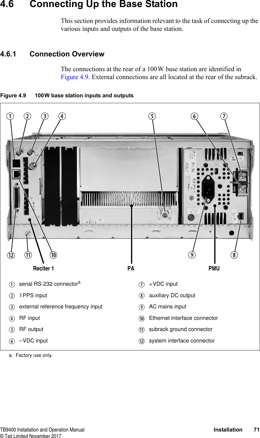
Tait Limited Base Station Receiver with Ethernet Port TB9400 Installation and Operation Manual

Exhibit D Users Manual per 2 1033 b3
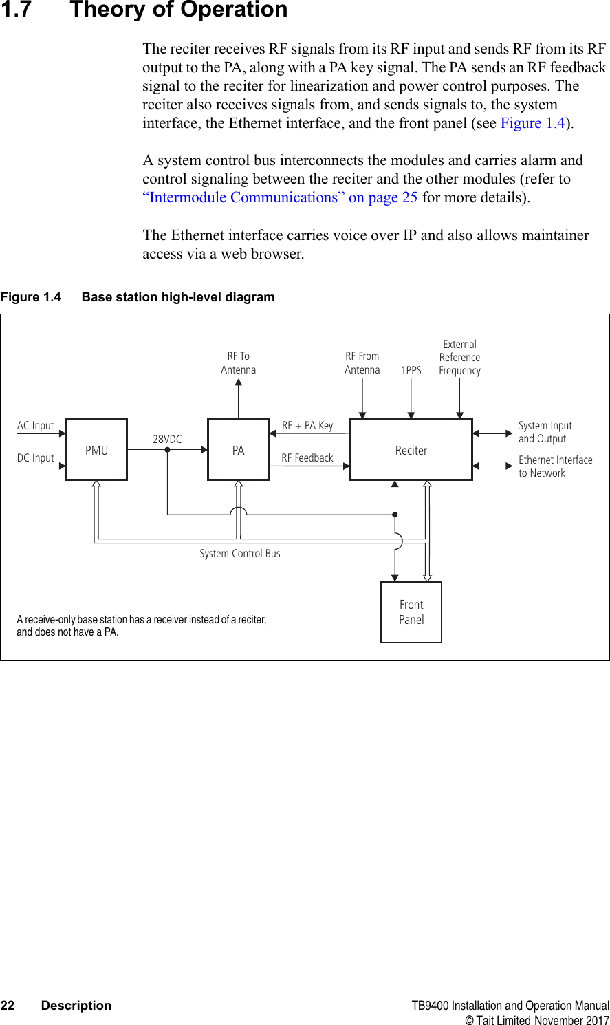
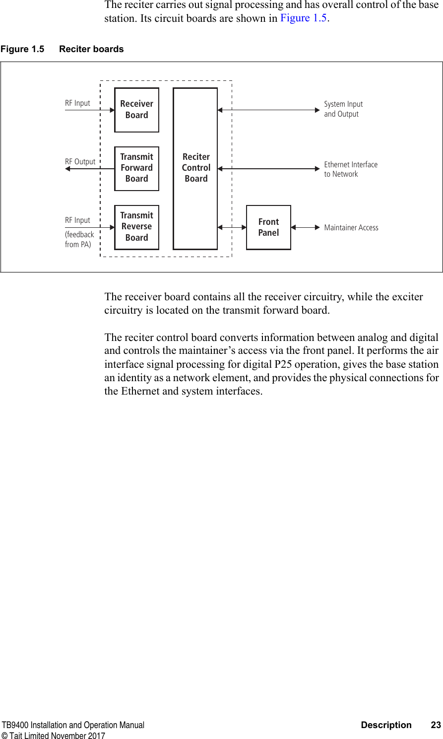
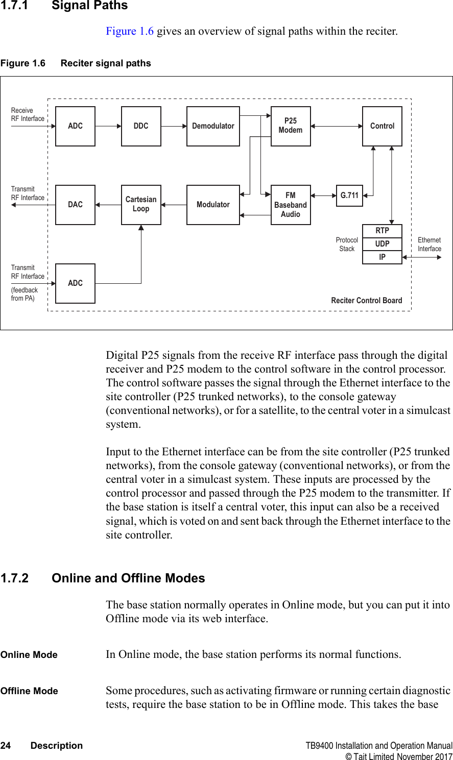
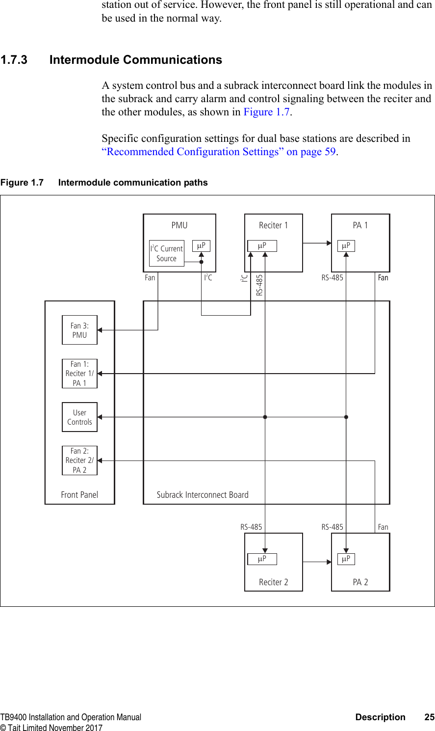
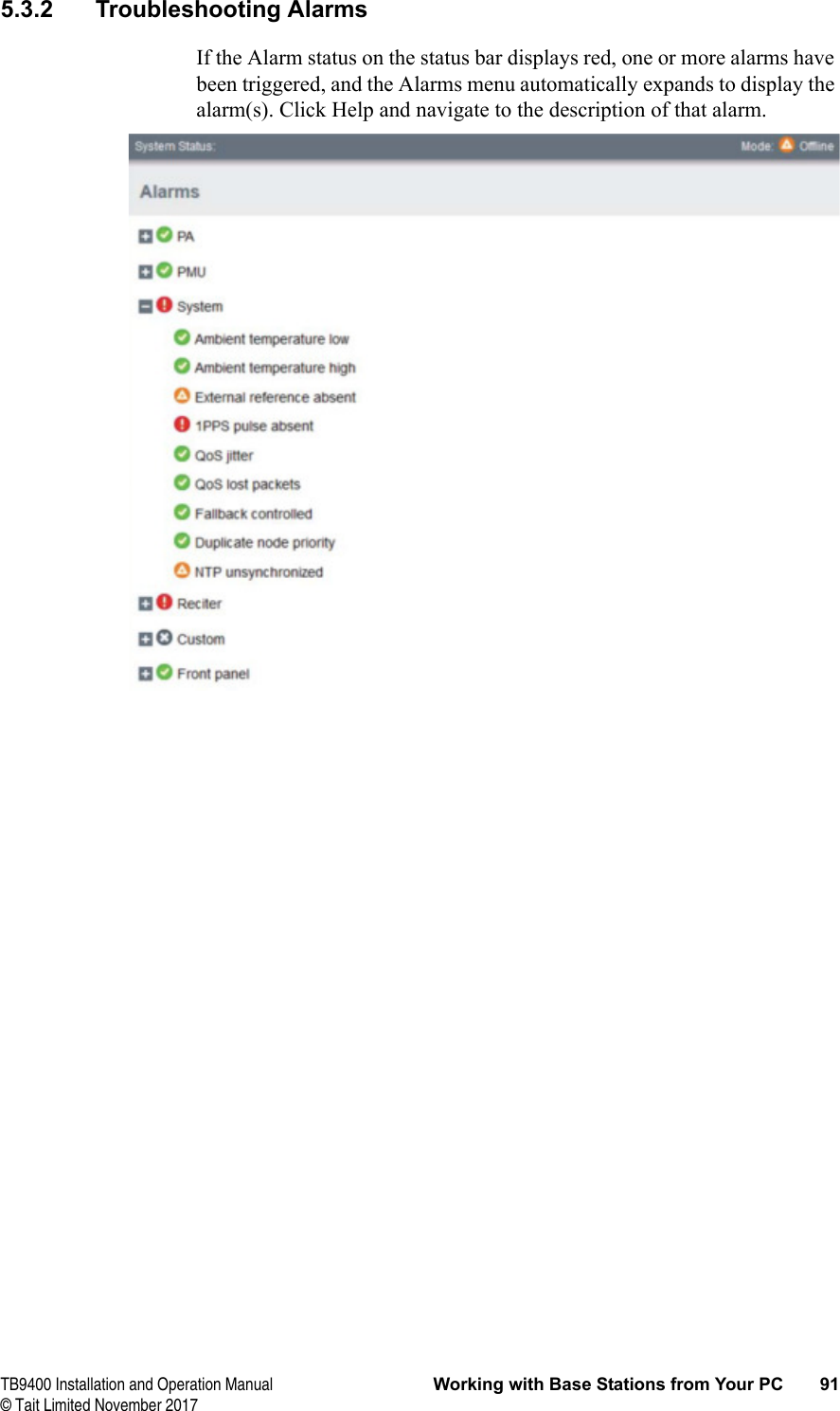
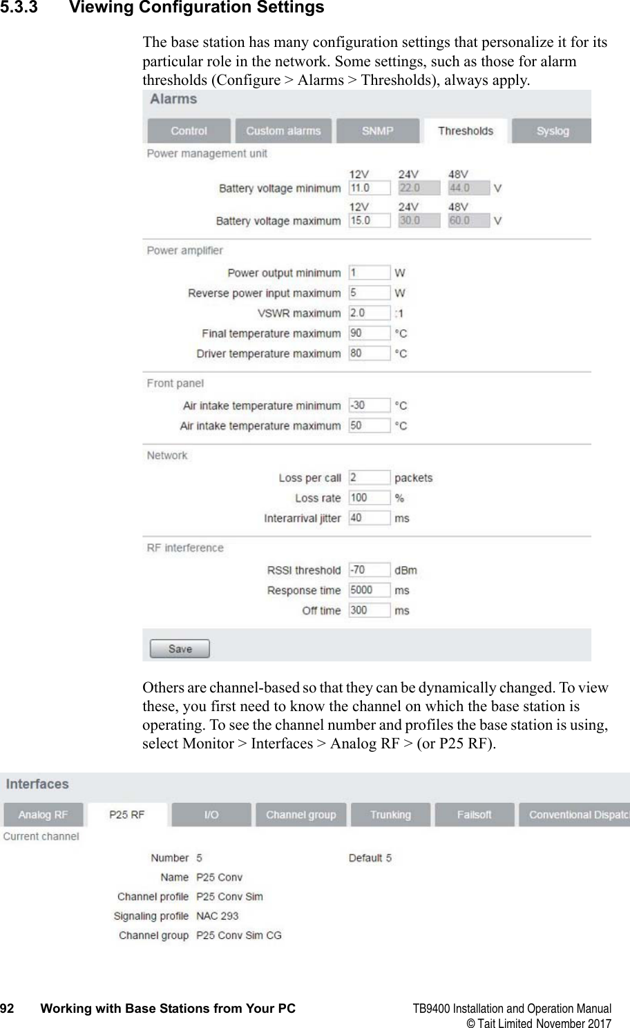
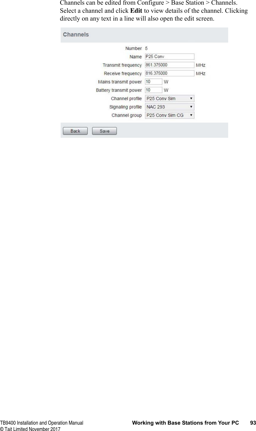
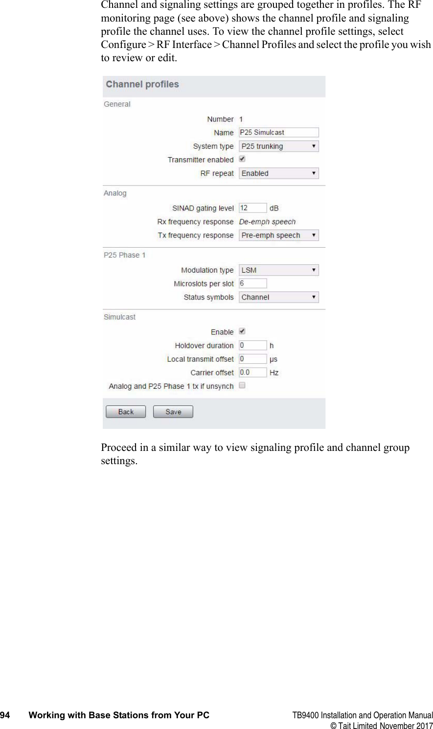
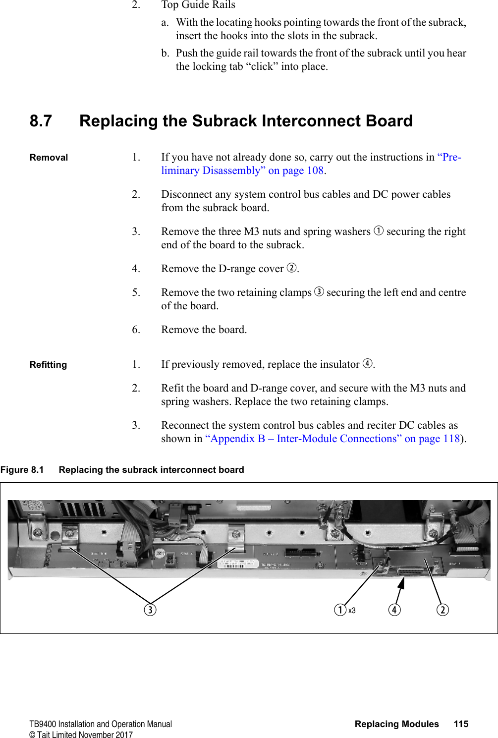
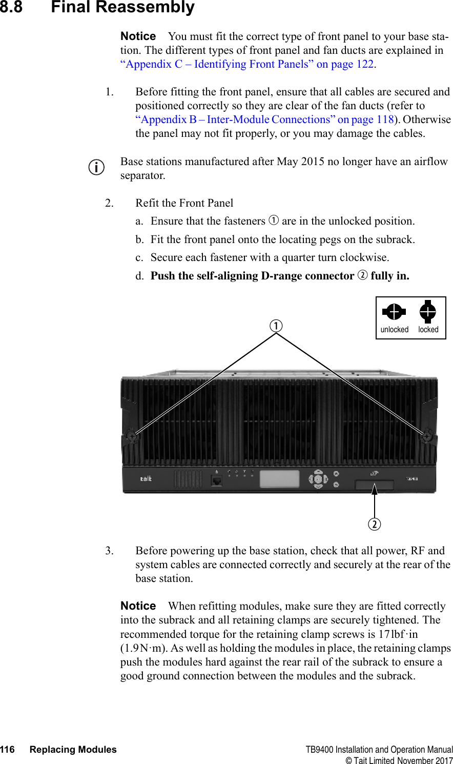
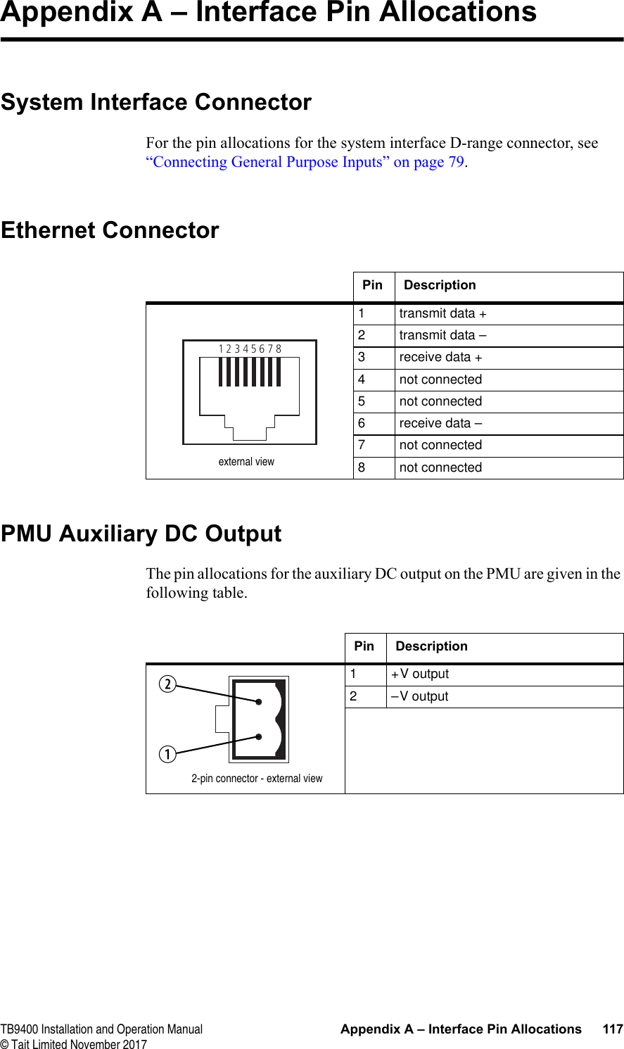
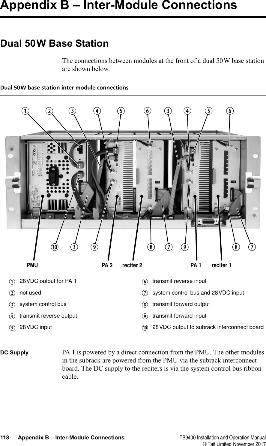
 TB9400 Base Station/RepeaterInstallation and Operation ManualMBC-00001-17 · Issue 17 · November 2017
 2TB9400 Installation and Operation Manual© Tait Limited November 2017Contact InformationTait CommunicationsCorporate Head OfficeTait LimitedP.O. Box 1645ChristchurchNew ZealandFor the address and telephone number of regional offices, refer to our website: www.taitradio.comCopyright and TrademarksAll information contained in this document is the property of Tait Limited. All rights reserved. This document may not, in whole or in part, be copied, photocopied, reproduced, translated, stored, or reduced to any electronic medium or machine-readable form, without prior written permission from Tait Limited.The word TAIT and the TAIT logo are trademarks of Tait Limited.All trade names referenced are the service mark, trademark or registered trademark of the respective manufacturers.DisclaimerThere are no warranties extended or granted by this document. Tait Limited accepts no responsibility for damage arising from use of the information contained in the document or of the equipment and software it describes. It is the responsibility of the user to ensure that use of such information, equipment and software complies with the laws, rules and regulations of the applicable jurisdictions.Enquiries and CommentsIf you have any enquiries regarding this document, or any comments, suggestions and notifications of errors, please contact your regional Tait office.Updates of Manual and EquipmentIn the interests of improving the performance, reliability or servicing of the equipment, Tait Limited reserves the right to update the equipment or this document or both without prior notice.Intellectual Property RightsThis product may be protected by one or more patents or designs of Tait Limited together with their international equivalents, pending patent or design applications, and registered trade marks: NZ409837, NZ409838, NZ415277, NZ415278, NZ530819, NZ534475, NZ547713, NZ577009, NZ579051, NZ579364, NZ586889, NZ610563, NZ615954, NZ700387, NZ708662, NZ710766, NZ711325 , NZ726313, NZ593887, AU2015215962, AU339127, AU339391, AU2016259281, AU2016902579, EU000915475-0001, EU000915475-0002, GB2532863, US14/834609 Div. no 1, US15/346518 Div.no 2, US15/350332, US15/387026 Div., US20150085799, US20160044572, US20160057051, US640974, US640977, US698339, US702666, US7758996, US8902804, US9107231, US9504034, US9559967.The AMBE+2™ voice coding Technology embodied in this product is protected by intellectual property rights including patent rights, copyrights and trade secrets of Digital Voice Systems, Inc. This voice coding Technology is licensed solely for use within this Communications Equipment. The user of this Technology is explicitly prohibited from attempting to decompile, reverse engineer, or disassemble the Object Code, or in any other way convert the Object Code into a human-readable form.Environmental ResponsibilitiesTait Limited is an environmentally responsible company which supports waste minimization, material recovery and restrictions in the use of hazardous materials. The European Union’s Waste Electrical and Electronic Equipment (WEEE) Directive requires that this product be disposed of separately from the general waste stream when its service life is over. For more information about how to dispose of your unwanted Tait product, visit the Tait WEEE website at www.taitradio.com/weee. Please be environmentally responsible and dispose through the original supplier, or contact Tait Limited.Tait Limited also complies with the Restriction of the Use of Certain Hazardous Substances in Electrical and Electronic Equipment (RoHS) Directive in the European Union.In China, we comply with the Measures for Administration of the Pollution Control of Electronic Information Products. We will comply with environmental requirements in other markets as they are introduced.
 TB9400 Installation and Operation Manual 3© Tait Limited November 2017ContentsPreface . . . . . . . . . . . . . . . . . . . . . . . . . . . . . . . . . . . . . . . . . . . . . . . . . . . . . . . . . . . . . . . . . . . . .  7Scope of Manual. . . . . . . . . . . . . . . . . . . . . . . . . . . . . . . . . . . . . . . . . . . . . . . . . . . . . . . .  7Document Conventions  . . . . . . . . . . . . . . . . . . . . . . . . . . . . . . . . . . . . . . . . . . . . . . . . . .  7Associated Documentation. . . . . . . . . . . . . . . . . . . . . . . . . . . . . . . . . . . . . . . . . . . . . . . .  8Publication Records . . . . . . . . . . . . . . . . . . . . . . . . . . . . . . . . . . . . . . . . . . . . . . . . . . . . .  91 Description . . . . . . . . . . . . . . . . . . . . . . . . . . . . . . . . . . . . . . . . . . . . . . . . . . . . . . . . . . . . .  101.1 Features  . . . . . . . . . . . . . . . . . . . . . . . . . . . . . . . . . . . . . . . . . . . . . . . . . . . . . . . . . .111.2 Modules . . . . . . . . . . . . . . . . . . . . . . . . . . . . . . . . . . . . . . . . . . . . . . . . . . . . . . . . .  121.3 Mechanical Assembly  . . . . . . . . . . . . . . . . . . . . . . . . . . . . . . . . . . . . . . . . . . . . . .  151.4 Frequency Bands and Sub-bands . . . . . . . . . . . . . . . . . . . . . . . . . . . . . . . . . . . . . .  181.5 Applications . . . . . . . . . . . . . . . . . . . . . . . . . . . . . . . . . . . . . . . . . . . . . . . . . . . . . .  191.6 Licenses . . . . . . . . . . . . . . . . . . . . . . . . . . . . . . . . . . . . . . . . . . . . . . . . . . . . . . . . .  201.7 Theory of Operation. . . . . . . . . . . . . . . . . . . . . . . . . . . . . . . . . . . . . . . . . . . . . . . .  221.7.1 Signal Paths . . . . . . . . . . . . . . . . . . . . . . . . . . . . . . . . . . . . . . . . . . . . . .  241.7.2 Online and Offline Modes . . . . . . . . . . . . . . . . . . . . . . . . . . . . . . . . . . .  241.7.3 Intermodule Communications . . . . . . . . . . . . . . . . . . . . . . . . . . . . . . . .  251.7.4 Power Management and Distribution . . . . . . . . . . . . . . . . . . . . . . . . . .  261.7.5 PMU Operation on DC Input. . . . . . . . . . . . . . . . . . . . . . . . . . . . . . . . .  281.7.6 Front Panel Fans  . . . . . . . . . . . . . . . . . . . . . . . . . . . . . . . . . . . . . . . . . .  312 General Safety and Regulatory Information  . . . . . . . . . . . . . . . . . . . . . . . . . . . . . . . . .  322.1 Personal Safety. . . . . . . . . . . . . . . . . . . . . . . . . . . . . . . . . . . . . . . . . . . . . . . . . . . .  322.1.1 Unpacking and Moving the Equipment. . . . . . . . . . . . . . . . . . . . . . . . .  322.1.2 Lethal Voltages  . . . . . . . . . . . . . . . . . . . . . . . . . . . . . . . . . . . . . . . . . . .  322.1.3 AC Power Connection. . . . . . . . . . . . . . . . . . . . . . . . . . . . . . . . . . . . . .  332.1.4 Explosive Environments . . . . . . . . . . . . . . . . . . . . . . . . . . . . . . . . . . . .  332.1.5 High Temperatures. . . . . . . . . . . . . . . . . . . . . . . . . . . . . . . . . . . . . . . . .  332.1.6 LED Safety (EN60825-1) . . . . . . . . . . . . . . . . . . . . . . . . . . . . . . . . . . .  332.1.7 Proximity to RF Transmissions / A proximité des émissions RF . . . . .  342.2 Equipment Safety. . . . . . . . . . . . . . . . . . . . . . . . . . . . . . . . . . . . . . . . . . . . . . . . . .  352.2.1 Installation and Servicing Personnel . . . . . . . . . . . . . . . . . . . . . . . . . . .  352.2.2 Preventing Damage to the PA . . . . . . . . . . . . . . . . . . . . . . . . . . . . . . . .  352.2.3 ESD Precautions . . . . . . . . . . . . . . . . . . . . . . . . . . . . . . . . . . . . . . . . . .  352.2.4 Anti-tampering Devices. . . . . . . . . . . . . . . . . . . . . . . . . . . . . . . . . . . . .  362.3 Environmental Conditions . . . . . . . . . . . . . . . . . . . . . . . . . . . . . . . . . . . . . . . . . . .  362.3.1 Operating Temperature Range. . . . . . . . . . . . . . . . . . . . . . . . . . . . . . . .  362.3.2 Humidity . . . . . . . . . . . . . . . . . . . . . . . . . . . . . . . . . . . . . . . . . . . . . . . .  362.3.3 Dust and Dirt . . . . . . . . . . . . . . . . . . . . . . . . . . . . . . . . . . . . . . . . . . . . .  362.4 Regulatory Information . . . . . . . . . . . . . . . . . . . . . . . . . . . . . . . . . . . . . . . . . . . . .  372.4.1 Distress Frequencies . . . . . . . . . . . . . . . . . . . . . . . . . . . . . . . . . . . . . . .  37
 4TB9400 Installation and Operation Manual© Tait Limited November 20172.4.2 Compliance Standards . . . . . . . . . . . . . . . . . . . . . . . . . . . . . . . . . . . . . .  372.4.3 FCC Compliance . . . . . . . . . . . . . . . . . . . . . . . . . . . . . . . . . . . . . . . . . .  372.4.4 Unauthorized Modifications  . . . . . . . . . . . . . . . . . . . . . . . . . . . . . . . . .  373 Operation . . . . . . . . . . . . . . . . . . . . . . . . . . . . . . . . . . . . . . . . . . . . . . . . . . . . . . . . . . . . . .  383.1 Front Panel . . . . . . . . . . . . . . . . . . . . . . . . . . . . . . . . . . . . . . . . . . . . . . . . . . . . . . .  393.2 Module Indicator LEDs and Switches . . . . . . . . . . . . . . . . . . . . . . . . . . . . . . . . . .  433.2.1 Reciter and Receiver  . . . . . . . . . . . . . . . . . . . . . . . . . . . . . . . . . . . . . . .  433.2.2 PA. . . . . . . . . . . . . . . . . . . . . . . . . . . . . . . . . . . . . . . . . . . . . . . . . . . . . .  453.2.3 PMU. . . . . . . . . . . . . . . . . . . . . . . . . . . . . . . . . . . . . . . . . . . . . . . . . . . .  464 Installation . . . . . . . . . . . . . . . . . . . . . . . . . . . . . . . . . . . . . . . . . . . . . . . . . . . . . . . . . . . . .  484.1 Before You Begin . . . . . . . . . . . . . . . . . . . . . . . . . . . . . . . . . . . . . . . . . . . . . . . . . .  494.1.1 Equipment Security . . . . . . . . . . . . . . . . . . . . . . . . . . . . . . . . . . . . . . . .  494.1.2 Grounding and Lightning Protection . . . . . . . . . . . . . . . . . . . . . . . . . . .  494.1.3 Equipment Ventilation . . . . . . . . . . . . . . . . . . . . . . . . . . . . . . . . . . . . . .  494.1.4 Ambient Temperature Sensor. . . . . . . . . . . . . . . . . . . . . . . . . . . . . . . . .  494.1.5 Cabinet and Rack Ventilation. . . . . . . . . . . . . . . . . . . . . . . . . . . . . . . . .  504.2 Unpacking and Moving the Subrack  . . . . . . . . . . . . . . . . . . . . . . . . . . . . . . . . . . .  524.3 Identifying the Equipment . . . . . . . . . . . . . . . . . . . . . . . . . . . . . . . . . . . . . . . . . . .  544.4 Initial Setting Up  . . . . . . . . . . . . . . . . . . . . . . . . . . . . . . . . . . . . . . . . . . . . . . . . . .  564.4.1 Confirming Operation . . . . . . . . . . . . . . . . . . . . . . . . . . . . . . . . . . . . . .  564.4.2 Working with Configurations. . . . . . . . . . . . . . . . . . . . . . . . . . . . . . . . .  584.4.3 Customizing the Configuration . . . . . . . . . . . . . . . . . . . . . . . . . . . . . . .  594.4.4 Recommended Configuration Settings  . . . . . . . . . . . . . . . . . . . . . . . . .  594.4.5 Restricted Port Numbers  . . . . . . . . . . . . . . . . . . . . . . . . . . . . . . . . . . . .  594.4.6 Changing the Root Password . . . . . . . . . . . . . . . . . . . . . . . . . . . . . . . . .  604.4.7 Tuning the Reciter and Receiver . . . . . . . . . . . . . . . . . . . . . . . . . . . . . .  614.5 Installing the Base Station on Site . . . . . . . . . . . . . . . . . . . . . . . . . . . . . . . . . . . . .  654.5.1 General Installation Advice . . . . . . . . . . . . . . . . . . . . . . . . . . . . . . . . . .  654.5.2 Equipment Required  . . . . . . . . . . . . . . . . . . . . . . . . . . . . . . . . . . . . . . .  664.5.3 Mounting the Subrack . . . . . . . . . . . . . . . . . . . . . . . . . . . . . . . . . . . . . .  674.6 Connecting Up the Base Station. . . . . . . . . . . . . . . . . . . . . . . . . . . . . . . . . . . . . . .  714.6.1 Connection Overview  . . . . . . . . . . . . . . . . . . . . . . . . . . . . . . . . . . . . . .  714.6.2 Connecting AC Power . . . . . . . . . . . . . . . . . . . . . . . . . . . . . . . . . . . . . .  724.6.3 Connecting DC Power . . . . . . . . . . . . . . . . . . . . . . . . . . . . . . . . . . . . . .  734.6.4 Connecting the Auxiliary DC Power Output. . . . . . . . . . . . . . . . . . . . .  744.6.5 Connecting RF . . . . . . . . . . . . . . . . . . . . . . . . . . . . . . . . . . . . . . . . . . . .  754.6.6 Connecting an External Frequency Reference. . . . . . . . . . . . . . . . . . . .  764.6.7 Connecting a 1PPS Source  . . . . . . . . . . . . . . . . . . . . . . . . . . . . . . . . . .  774.6.8 Ethernet Connection. . . . . . . . . . . . . . . . . . . . . . . . . . . . . . . . . . . . . . . .  784.6.9 Connecting General Purpose Inputs. . . . . . . . . . . . . . . . . . . . . . . . . . . .  795 Working with Base Stations from Your PC . . . . . . . . . . . . . . . . . . . . . . . . . . . . . . . . . . .  805.1 PC Recommendations  . . . . . . . . . . . . . . . . . . . . . . . . . . . . . . . . . . . . . . . . . . . . . .  815.2 Connecting Your PC to the Base Station . . . . . . . . . . . . . . . . . . . . . . . . . . . . . . . .  815.2.1 Logging In . . . . . . . . . . . . . . . . . . . . . . . . . . . . . . . . . . . . . . . . . . . . . . .  82
 TB9400 Installation and Operation Manual 5© Tait Limited November 20175.2.2 Setting the IP Address . . . . . . . . . . . . . . . . . . . . . . . . . . . . . . . . . . . . . .  835.2.3 Security Certificates  . . . . . . . . . . . . . . . . . . . . . . . . . . . . . . . . . . . . . . .  845.2.4 Connecting a Networked PC to a Base Station . . . . . . . . . . . . . . . . . . .  855.2.5 Troubleshooting Connection Problems . . . . . . . . . . . . . . . . . . . . . . . . .  875.2.6 Finding a Lost or Forgotten IP Address  . . . . . . . . . . . . . . . . . . . . . . . .  875.2.7 Setting Up Authentication . . . . . . . . . . . . . . . . . . . . . . . . . . . . . . . . . . .  885.3 Working with the Web Interface  . . . . . . . . . . . . . . . . . . . . . . . . . . . . . . . . . . . . . .  895.3.1 Monitoring Operation . . . . . . . . . . . . . . . . . . . . . . . . . . . . . . . . . . . . . .  905.3.2 Troubleshooting Alarms  . . . . . . . . . . . . . . . . . . . . . . . . . . . . . . . . . . . .  915.3.3 Viewing Configuration Settings  . . . . . . . . . . . . . . . . . . . . . . . . . . . . . .  925.3.4 Viewing the Base Station and Network Identity . . . . . . . . . . . . . . . . . .  955.4 Basic Tasks. . . . . . . . . . . . . . . . . . . . . . . . . . . . . . . . . . . . . . . . . . . . . . . . . . . . . . .  965.4.1 User Settings . . . . . . . . . . . . . . . . . . . . . . . . . . . . . . . . . . . . . . . . . . . . .  965.4.2 Taking the Base Station Offline. . . . . . . . . . . . . . . . . . . . . . . . . . . . . . .  965.4.3 Troubleshooting Alarms  . . . . . . . . . . . . . . . . . . . . . . . . . . . . . . . . . . . .  965.4.4 Working with Configuration Files. . . . . . . . . . . . . . . . . . . . . . . . . . . . .  975.4.5 Configuring Single Base Stations . . . . . . . . . . . . . . . . . . . . . . . . . . . . .  985.4.6 Configuring Receive-Only Base Stations . . . . . . . . . . . . . . . . . . . . . . .  985.4.7 Configuring Base Stations in a Channel Group. . . . . . . . . . . . . . . . . . .  985.4.8 Setting Up Custom Alarms . . . . . . . . . . . . . . . . . . . . . . . . . . . . . . . . . .  995.4.9 Disabling the Front Panel Keypad. . . . . . . . . . . . . . . . . . . . . . . . . . . .  1005.4.10 Preparing to Download Firmware . . . . . . . . . . . . . . . . . . . . . . . . . . . .  1005.4.11 Checking for Interference on a Receive Channel . . . . . . . . . . . . . . . .  1026 Maintenance. . . . . . . . . . . . . . . . . . . . . . . . . . . . . . . . . . . . . . . . . . . . . . . . . . . . . . . . . . .  1037 Troubleshooting . . . . . . . . . . . . . . . . . . . . . . . . . . . . . . . . . . . . . . . . . . . . . . . . . . . . . . . . 1058 Replacing Modules  . . . . . . . . . . . . . . . . . . . . . . . . . . . . . . . . . . . . . . . . . . . . . . . . . . . . .  1068.1 Saving the Base Station’s Configuration . . . . . . . . . . . . . . . . . . . . . . . . . . . . . . .  1078.2 Preliminary Disassembly . . . . . . . . . . . . . . . . . . . . . . . . . . . . . . . . . . . . . . . . . . .  1088.3 Replacing a Reciter  . . . . . . . . . . . . . . . . . . . . . . . . . . . . . . . . . . . . . . . . . . . . . . . .1108.4 Replacing a Power Amplifier. . . . . . . . . . . . . . . . . . . . . . . . . . . . . . . . . . . . . . . . .1128.5 Replacing a Power Management Unit . . . . . . . . . . . . . . . . . . . . . . . . . . . . . . . . . .1138.6 Replacing the Module Guide Rails  . . . . . . . . . . . . . . . . . . . . . . . . . . . . . . . . . . . .1148.7 Replacing the Subrack Interconnect Board . . . . . . . . . . . . . . . . . . . . . . . . . . . . . .1158.8 Final Reassembly . . . . . . . . . . . . . . . . . . . . . . . . . . . . . . . . . . . . . . . . . . . . . . . . . .116Appendix A – Interface Pin Allocations . . . . . . . . . . . . . . . . . . . . . . . . . . . . . . . . . . . . . . . . .117System Interface Connector . . . . . . . . . . . . . . . . . . . . . . . . . . . . . . . . . . . . . . . . . . . . . .117Ethernet Connector. . . . . . . . . . . . . . . . . . . . . . . . . . . . . . . . . . . . . . . . . . . . . . . . . . . . .117PMU Auxiliary DC Output  . . . . . . . . . . . . . . . . . . . . . . . . . . . . . . . . . . . . . . . . . . . . . .117Appendix B – Inter-Module Connections . . . . . . . . . . . . . . . . . . . . . . . . . . . . . . . . . . . . . . . .118Dual 50W Base Station  . . . . . . . . . . . . . . . . . . . . . . . . . . . . . . . . . . . . . . . . . . . . . . . . .118
 6TB9400 Installation and Operation Manual© Tait Limited November 2017Single 50W Base Station . . . . . . . . . . . . . . . . . . . . . . . . . . . . . . . . . . . . . . . . . . . . . . .  119100W Base Station . . . . . . . . . . . . . . . . . . . . . . . . . . . . . . . . . . . . . . . . . . . . . . . . . . . .  120Receive-only Base Station . . . . . . . . . . . . . . . . . . . . . . . . . . . . . . . . . . . . . . . . . . . . . .  121Appendix C – Identifying Front Panels  . . . . . . . . . . . . . . . . . . . . . . . . . . . . . . . . . . . . . . . .  122Glossary . . . . . . . . . . . . . . . . . . . . . . . . . . . . . . . . . . . . . . . . . . . . . . . . . . . . . . . . . . . . . . . . . .  123Tait Software License Agreement  . . . . . . . . . . . . . . . . . . . . . . . . . . . . . . . . . . . . . . . . . . . . .  129Directive 1999/5/EC Declaration of Conformity  . . . . . . . . . . . . . . . . . . . . . . . . . . . . . . . . .  133
 TB9400 Installation and Operation Manual Preface 7© Tait Limited November 2017PrefaceScope of ManualThis manual provides information on installing and operating the TB9400 base station. It is intended for use by experienced technicians familiar with installing and operating base station equipment. It also includes configuration, maintenance and troubleshooting information.Except where stated otherwise, the information in this manual generally applies to both standard and receive-only base stations and reciters. When “reciter” is referred to, this generally applies also to the receiver (receive-only reciter). References to power amplifiers (PAs) and trans-mitting obviously do not apply to receive-only equipment.Unless mentioned specifically, this manual will use the term “base station” to refer to both base station and repeater.Document ConventionsThe TB9400 base station has a web interface with an accordion menu on the left side of the screen. “Configure > Base Station > Channels” means click Configure in the top-level menu, then in the expanded Configure menu click Base Station, and finally click on the Channels tab on that page.Within this manual, four types of alerts may be given to the reader. The following paragraphs illustrate each type of alert and its associated symbol.Warning This alert is used when there is a hazardous situation which, if not avoided, could result in death or serious injury.Caution This alert is used when there is a hazardous situation which, if not avoided, could result in minor or moderate injury.Notice This alert is used to highlight information that is required to ensure procedures are performed correctly. Incorrectly performed pro-cedures could result in equipment damage or malfunction.This icon is used to draw your attention to information that may improve your understanding of the equipment or procedure.
 8 Preface TB9400 Installation and Operation Manual© Tait Limited November 2017Associated DocumentationThe following associated documentation for this product is available on the Tait support website.■TB9400 Specifications Manual (MBC-00002-xx)■TN9400 P25 Trunked Network Maintenance Manual (MNC-00001-xx)■TaitNet P25 Trunked Networks with TB9400 Base Stations System Manual (MBA-00064-xx)■TaitNet Analog Conventional Networks with TB9400 Base Stations System Manual (MND-00001-xx)■Safety and Compliance Information (MBA-00012-xx)The characters xx represent the issue number of the documentation.Technical notes are published from time to time to describe applications for Tait products, to provide technical details not included in manuals, and to offer solutions for any problems that arise. Technical notes are available in PDF format from the Tait support website. For more information contact your regional Tait office.
 TB9400 Installation and Operation Manual Preface 9© Tait Limited November 2017Publication RecordsIssue Publication Date Description8 November 2014 General updates for version 1.45 release. Information added for P25 Phase 2 licenses.9 March 2015 General updates for version 2.00 release. Information added on P25 Phase 2 operation.10 July 2015 General updates for version 2.05 release. Information added for receive-only base stations and receiver modules, feature licenses, uploading security certificates, and external frequency reference stability requirements.11 November 2015 General updates for version 2.10 release. Information added for analog base stations. Feature license names updated.12 March 2016 General updates for version 2.15 release.Clarification of repeater vs. base station for K band in Brazil added.13 June 2016 General updates for version 2.20 release.Added P25 Conventional features, modified licence table, updated and annotated images and general updates.14 November 2016 General updates for version 2.25 release:Added Working with Configurations.Updated images in Troubleshooting Alarms and Viewing Configuration Settings.Added the TBAS060 DFSI license.Added an explanation of channels profiles and how to work with them on the WUI.15 March 2017 General updates for version 2.30 release.Updated description for the TBAS060 within Licenses on page 20.Updated description of modulation types in Features on page 11 - bullet points 1 and 3.Added statement that central voter and satellite licences are not both required.Information added regarding variations of front panel to Front Panel on page 13Added statement informing clients to change default passwords.16 July 2017 General updates for version 2.35 release.General minor wording and content changes throughoutAdded P25 Conventional Simulcast Repeater to Features on page 11Central voter and satellite licences listed as alternatives Licenses on page 20.Updated description for the ‘Digital Fixed Station’ Interface in Licenses on page 20.Updated the “Licenses and applicability” table for Central Voter, IP Networking Satellite, and Simulcast.Added new H3 band information throughout.Screenshots have been updated in various places.17 November 2017 General updates for the 2.40 release.Added definition of “integral voter” to Glossary on page 123Added solution to Internet Explorer black screen in Connecting Your PC to the Base Station on page 81.Added notice regarding fan operation to Front Panel Fans on page 31.Added information on cancelling a firmware package to Preparing to Download Firmware on page 100.Updated information on downloading firmware packages Setting Up a Central Package Server on page 101.Added notice regarding the base station resetting to Setting the IP Address on page 83.Added new HH band information throughout.
 10 Description TB9400 Installation and Operation Manual© Tait Limited November 20171DescriptionThe Tait TB9400 base station is a robust state-of-the-art digital fixed station that combines Tait’s proven strengths in reliability, high performance and modular design with software-based configurability and operation, digital signal processing, and voice-over-IP technology.The TB9400 operates as a transceiver in Project 25 trunked, trunked simulcast, and P25 conventional networks. It is capable of either P25 Phase 1 FDMA operation, or 6.25kHz equivalent P25 Phase 2 TDMA operation.The TB9400 can also operate in an analog conventional simulcast or non-simulcast multi-site network.The TB9400 combines industry-leading digital voice quality with rugged design specifications and intuitive user interfaces. These products are designed to meet the needs of the public safety and public service sectors.The ability of the base station to link stations using standard Internet Protocol communications, and to add features through software options ensures that P25 systems designed with the TB9400 are scalable in both size and functionality.Its Ethernet interface provides built-in network connectivity, allowing the TB9400 to join with other TB9400 base stations to form a channel group. This network supports voice-over-IP and remote management of all base stations via a web browser.
 TB9400 Installation and Operation Manual Description 11© Tait Limited November 20171.1 FeaturesThe following are some of the features of the base station:■Fully compliant with the P25 Common Air Interface. Can therefore interoperate with any similarly compliant radios.■Supports P25 Phase 1 operation with either C4FM or LSM modulation on the transmitter■Supports P25 Phase 2 operation.■Analog conventional repeater operation.■Analog conventional simulcast operation on an IP backbone requiring no audio calibration or training.■Integrated built-in voting facility. No external voter is needed.■Can be completely managed remotely from a PC running a web browser: configuration, alarm monitoring, fault diagnosis, feature and firmware upgrades. Alarms can also be reported via SNMP traps, allowing integration with an SNMP-based network management system.■An integrated wiring solution is provided for the system control bus and DC power connections to each module in the subrack.■Reciters (receiver/exciter modules) can be replaced without affecting the operation of other reciters in the same subrack.■Rugged construction with generous heatsinks and fan-forced cooling for continuous operation from –22°F to +140°F (–30°C to +60°C).
 12 Description TB9400 Installation and Operation Manual© Tait Limited November 20171.2 ModulesThe base station consists of a subrack with up to two transmit/receive channels, or up to four receive-only channels.Receive-only base stations are currently available for operation only on B3 band (148MHz to 174MHz), H1 band (400MHz to 440MHz), H2 band (440MHz to 480MHz), H3 band (470MHz to 520MHz), and K4 band (762MHz to 870MHz)1.The single PMU (power management unit) supplies and manages power to the whole subrack (refer to “Theory of Operation” on page 22). One reciter and one PA (power amplifier) are needed for each transmit/receive channel. The PA is not required for a receive-only base station. There is also a front panel with user controls and fans. The modules are interconnected at the front of the subrack. External connections to the modules are located at the rear.Modules come in different variants depending, for example, on the RF band or the supply voltage.Each module is inserted into the 4U subrack from the front and is secured at the front with a metal clamp. Both clamp and module are easily removed for rapid module replacement. The modules are secured laterally with plastic guides that clip into the top and bottom of the subrack. These guides can be easily repositioned to change the configuration of a subrack. The heavier modules are also secured laterally by metal tabs at the rear of the subrack.The following provides a brief description of the available modules.Subrack The 4U subrack is made of passivated steel and is designed to fit into a standard 19 inch rack or cabinet. The subrack is fitted with an interconnect board that connects the system control bus and power to the modules and front panel. The position of a module in the subrack is defined by the socket on the subrack interconnect board to which the module is connected by the system control bus. 1. Refer to “Frequency Bands and Sub-bands” on page 18.
 TB9400 Installation and Operation Manual Description 13© Tait Limited November 2017Front Panel The front panel is mounted onto the subrack with two quick-release fasteners. It incorporates the indicator LEDs, four-line LCD display, user controls, ambient temperature sensor and cooling fans.The indicator LEDS allow some monitoring of the operational status of the base station. The user controls and display allow the technician to configure the IP address of each module. Refer to “Front Panel” on page 39 for more information.The base stations have different front panel ducting arrangements depending on PA type and power. Front panels may not be interchange-able.The microphone input and speaker are not used in this release of the TB9400.Reciter The reciter module comprises the receiver, exciter and digital control circuitry. The reciter provides the Ethernet interface and system inputs and outputs.Receiver modules (receive-only reciters) are not fitted with the transmit circuitry or front panel SMA connectors, and are physically unable to transmit.reciter receiver
 14 Description TB9400 Installation and Operation Manual© Tait Limited November 2017Power Amplifier The PA amplifies the RF output from the reciter and is available in 50W and 100W models.The 50W model mounts vertically in the subrack, while the 100W model mounts horizontally as it has a wider heatsink. The 100W PA is also fitted with an airflow duct.Both models are designed to operate on the 28VDC output provided by the PMU. PAs are not required in a receive-only base station.Power Management UnitThe PMU provides the 28VDC power supply for the modules in the subrack. It can operate on 120/230VAC 50/60Hz nominal, and 12, 24 or 48VDC nominal. The input voltage can be AC, DC, or both AC and DC, depending on the model. The PMU also has an auxiliary DC output of 13.65VDC, 27.3VDC, or 54.6VDC, depending on the model.50W PA 100W PAAC and DC PMU shown
 TB9400 Installation and Operation Manual Description 15© Tait Limited November 20171.3 Mechanical AssemblyThis section illustrates the main mechanical components of the base station.Figure 1.1 below shows the configuration for a typical dual 50W base station. The subrack has six slots, numbered from right to left as viewed from the front of the subrack. The PMU occupies slots 5 and 6, with the reciter and PA pairs to the right of it in slots 1 to 4. Each PA is mounted vertically with its heatsink facing its associated reciter. The PMU and each reciter/PA pair have their own cooling fans.The front panel can be easily removed from the subrack by undoing two quick-release fasteners. Refer to “Replacing Modules” on page 106 for more details..Figure 1.1 Mechanical assembly - dual 50W base station with front panelbfront panel ireciter 1csubrack jmodule retaining clampdPMU 1) subrack interconnect boardePA 2 1! plastic guide railfreciter 2 1@ subrack interconnect board retaining clampgcable retaining clip 1# front panel fastenerhPA 1bcdefghij1)1!1@1#
 16 Description TB9400 Installation and Operation Manual© Tait Limited November 2017Figure 1.2 below shows the configuration for a typical single 50W base station. The PMU again occupies slots 5 and 6, with the reciter in slot 1 and PA in slot 2. The PA is mounted vertically with its heatsink facing the reciter. The PMU and the reciter/PA pair have their own cooling fans.Figure 1.2 Mechanical assembly - single 50W base stationbPMU dreciterc50W PA esubrackbcde
 TB9400 Installation and Operation Manual Description 17© Tait Limited November 2017Figure 1.3 below shows the configuration for a typical 100 W base station. The PMU occupies slots 5 and 6, with the PA directly beside it in slots 3 and 4. The reciter occupies slot 1. Unlike the 50W PAs, the 100W PA is mounted horizontally with the heatsink facing upwards. It is also fitted with an airflow duct to channel the airflow from the cooling fan through the heatsink fins.Figure 1.3 Mechanical assembly - single 100W base stationbPMU erecitercPA fsubrackdairflow duct gcable retaining clipbcdefg
 18 Description TB9400 Installation and Operation Manual© Tait Limited November 20171.4 Frequency Bands and Sub-bandsMuch of the circuitry in the base station is common to all frequency bands, and is therefore covered by a single description in this manual. In some cases the descriptions refer to specific bands or sub-bands, and these are identified with the letters listed in the following table.In Brazil, for K band, the TB9400 is considered to be configured as a base station with retransmission of received signals.Frequency Identification Frequency Band and Sub-band 50W 100W Receive-onlyB band B3 = 148MHz to 174MHz ✓✓ ✓H band HH = 378MHz to 420MHzH1 = 400MHz to 440MHzH2 = 440MHz to 480MHzH3 = 470MHz to 520MHz✘✓✓✓✓✓✓✓✘✓✓✓K band K4 = 762 MHz to 870MHza✓✓ ✓a. The actual frequency coverage in this band is:Transmit: 762MHz to 776MHz, and 850MHz to 870MHzReceive: 792MHz to 824MHz
 TB9400 Installation and Operation Manual Description 19© Tait Limited November 20171.5 ApplicationsThe TB9400 operates in P25 trunked networks (Phase 1 or Phase 2), P25 conventional networks and analog conventional networks. It operates as a stand-alone repeater/base station, or as part of a channel group, providing receiver voting and simulcast transmission. All air interfaces and system types support simulcast operation.In P25 Phase 2 operation, a single TB9400 base station can provide two traffic channels, since each radio frequency (physical channel) provides two logical channels (timeslots). However, it can provide only one control channel, since control channels are still P25 Phase 1.In a trunked simulcast network, the transmitters in the channel group are synchronized and transmit simultaneously on the same frequency. Each transmitter needs a highly accurate 1PPS pulse and an external frequency reference, so that it can time transmissions with the required accuracy. Also required is an NTP source that is derived from the same source as the 1PPS signal. This will ensure a common timestamp in logs across all units in the system. An external frequency reference, along with an NTP source and 1PPS signal derived from the same GPS source, are also essential for all reciters for P25 Phase 2 operation.In a P25 conventional network, the TB9400 operates as a single or wide area conventional repeater, with receiver voting and optional simulcast. Dispatch connection is via the Tait P25 Console Gateway, supporting conversion between P25 and analog consoles with MDC1200 signalling.In an analog conventional network it can operate as a repeater with CTCSS1 or DCS subaudible signaling.The base station can also operate as part of an analog conventional simulcast network and is fully IP-connected. The base station also features an internally integrated voter, and therefore requires no external voter.The base station can be provided as a receive-only variant in systems that need sites to enhance the receive coverage. The receiver module in a receive-only base station is physically unable to transmit.The base station can be configured for Shared Channel operation, to detect interference on the uplink, as long as the site controller is compatible.For more information on these applications, refer to the Help and appropriate Tait System Manual.1. Private Line (PL).
 20 Description TB9400 Installation and Operation Manual© Tait Limited November 20171.6 LicensesSome operational functions of the base station are controlled by licenses. These functions will not work unless you purchase the appropriate feature license and enable the feature set controlled by that license. The feature sets currently available are listed below.The central voter and satellite licences listed below are alternatives.Analog Air Interface(TBAS041 - Default Licence)This is the licence that accompanies the base station. A base station with this license can operate as a repeater in an analog conventional network.P25 Common Air Interface(TBAS050)Allows the base station to go into Online mode. Base stations are always provided with this license.P25 Trunking Operation(TBAS056)Allows the base station to participate in Trunking Operation. Without this feature, the base station cannot provide a control or a status connection to a trunking site controller and it cannot function as a control or traffic channel.Digital Fixed Station Interface (TBAS060)Allows the base station to integrate with dispatch consoles supporting DFSI (Digital Fixed Station Interface).Central Voter(TBAS061)P25 and analog. This feature allows a base station to act as a central voter.Simulcast(TBAS062)This feature is required in base stations that have transmitters and belong to a P25 Phase 1 simulcast or analog simulcast network1. It is also required in the central voter of a simulcast channel.2Linear Simulcast Modulation(TBAS065)P25 only. Allows the base station to transmit using the LSM modulation scheme1. This scheme allows increased site separation in simulcast networks. Also requires the Simulcast license (TBAS062).P25 Trunking Failsoft(TBAS063)Allows trunked channels that become isolated from a site controller to perform simple conventional operation and to interface to a digital dispatch system. If a trunked channel consists of several base stations in a channel group, only the central voter (normally the master) needs this license. It is then able to become the failsoft repeater for that channel group. 1. Not needed for receive-only base stations.2. The central voter in a simulcast channel needs the respective Phase 1 or Phase 2 simulcast license. Normally, a transceiver member of a simulcast channel will have a simulcast license, so this constraint should not be an issue.
 TB9400 Installation and Operation Manual Description 21© Tait Limited November 2017P25 Phase 2 Trunking(TBAS066)This feature allows the base station to operate in trunking mode using two-slot TDMA as defined by the P25 Phase 2 standards. P25 Phase 2 Simulcast(TBAS069)This feature is required in base stations that have transmitters and belong to a P25 Phase 2 simulcast network1. It is also required in the central voter of a P25 Phase 2 simulcast channel2. Also requires the P25 Phase 2 Trunking (TBAS066) and Simulcast (TBAS062) licenses. Tait also recommends adding the Linear Simulcast Modulation (TBAS065) license as it provides improved RF performance.IP Networking Satellite(TBAS071)All system types and all air interface types. This feature allows a base station to be part of a channel group without requiring the Central Voter (TBAS061) license.Table 1.1 Licenses and applicabilityLicence Name Air Interface System TypeTBAS041 Analog Air Interface Analog ConventionalTBAS060 Digital Fixed Station Interface Analog & P25 Phase 1 ConventionalTBAS061 Central Voter Analog & P25 Phase 1 & 2 Trunked, ConventionalTBAS071 IP Networking Satellite Analog & P25 Phase 1 & 2 Trunked, ConventionalTBAS062 Simulcast Analog & P25 Phase 1 & 2 Trunked, ConventionalTBAS050 P25 Common Air Interface P25 Phase 1 & 2 Trunked, ConventionalTBAS065 Linear Simulcast Modulation P25 Phase 1 & 2 Trunked, ConventionalTBAS056 P25 Trunking Operation P25 Phase 1 & 2 TrunkedTBAS063 P25 Trunking Failsoft P25 Phase 1 & 2 TrunkedTBAS066 P25 Phase 2 Trunking P25 Phase 1 & 2 TrunkedTBAS069 P25 Phase 2 Simulcast P25 Phase 2 Trunked
 22 Description TB9400 Installation and Operation Manual© Tait Limited November 20171.7 Theory of OperationThe reciter receives RF signals from its RF input and sends RF from its RF output to the PA, along with a PA key signal. The PA sends an RF feedback signal to the reciter for linearization and power control purposes. The reciter also receives signals from, and sends signals to, the system interface, the Ethernet interface, and the front panel (see Figure 1.4).A system control bus interconnects the modules and carries alarm and control signaling between the reciter and the other modules (refer to “Intermodule Communications” on page 25 for more details). The Ethernet interface carries voice over IP and also allows maintainer access via a web browser. Figure 1.4 Base station high-level diagramReciterPMU PARF ToAntennaRF FromAntenna 1PPSExternalReferenceFrequencyAC InputDC Input28VDCSystem Control BusRF+PAKeyRF FeedbackSystem Inputand OutputEthernet Interfaceto NetworkFrontPanelA receive-only base station has a receiver instead of a reciter, and does not have a PA.
 TB9400 Installation and Operation Manual Description 23© Tait Limited November 2017The reciter carries out signal processing and has overall control of the base station. Its circuit boards are shown in Figure 1.5.The receiver board contains all the receiver circuitry, while the exciter circuitry is located on the transmit forward board.The reciter control board converts information between analog and digital and controls the maintainer’s access via the front panel. It performs the air interface signal processing for digital P25 operation, gives the base station an identity as a network element, and provides the physical connections for the Ethernet and system interfaces.Figure 1.5 Reciter boardsRF InputRF Input(feedbackfrom PA)RF OutputReceiverBoardTransmitForwardBoardTransmitReverseBoardFrontPanelReciterControlBoardMaintainer AccessSystem Inputand OutputEthernet Interfaceto Network
 24 Description TB9400 Installation and Operation Manual© Tait Limited November 20171.7.1 Signal PathsFigure 1.6 gives an overview of signal paths within the reciter. Digital P25 signals from the receive RF interface pass through the digital receiver and P25 modem to the control software in the control processor. The control software passes the signal through the Ethernet interface to the site controller (P25 trunked networks), to the console gateway (conventional networks), or for a satellite, to the central voter in a simulcast system.Input to the Ethernet interface can be from the site controller (P25 trunked networks), from the console gateway (conventional networks), or from the central voter in a simulcast system. These inputs are processed by the control processor and passed through the P25 modem to the transmitter. If the base station is itself a central voter, this input can also be a received signal, which is voted on and sent back through the Ethernet interface to the site controller.1.7.2 Online and Offline ModesThe base station normally operates in Online mode, but you can put it into Offline mode via its web interface.Online Mode In Online mode, the base station performs its normal functions. Offline Mode Some procedures, such as activating firmware or running certain diagnostic tests, require the base station to be in Offline mode. This takes the base Figure 1.6 Reciter signal pathsModulatorDemodulator P25ModemFMBasebandAudioG.711ControlADC DDCDACRTPUDPIPTransmitRF InterfaceReceiveRF InterfaceEthernetInterfaceProtocolStackReciter Control BoardCartesianLoopADCTransmitRF Interface(feedbackfrom PA)
 TB9400 Installation and Operation Manual Description 25© Tait Limited November 2017station out of service. However, the front panel is still operational and can be used in the normal way. 1.7.3 Intermodule CommunicationsA system control bus and a subrack interconnect board link the modules in the subrack and carry alarm and control signaling between the reciter and the other modules, as shown in Figure 1.7. Specific configuration settings for dual base stations are described in “Recommended Configuration Settings” on page 59.Figure 1.7 Intermodule communication pathsFanIC2RS-485RS-485IC2FanFanPA 1mPSubrack Interconnect BoardReciter 1mPFront PanelFan 3:PMUFan 1:Reciter 1/PA 1Fan 2:Reciter 2/PA 2UserControlsPMUmPI C CurrentSource2RS-485RS-485 FanPA 2mPReciter 2mP
 26 Description TB9400 Installation and Operation Manual© Tait Limited November 20171.7.4 Power Management and DistributionThe PMU manages the supply of power to ensure uninterrupted operation of the base station. A range of parameters is monitored and these can trigger alarms that are sent to the reciter. Alarms can be monitored via the web interface and reported via SNMP traps; they are also recorded in the reciter’s internal log file.AC to DC ChangeoverWhen the PMU has an AC and a DC module, the base station can be powered by either the AC (mains) or the DC (battery) supply. The base station will default to the AC supply if both supplies are provided. If the AC supply becomes unavailable, a seamless changeover from the AC to DC supply takes place, providing that the battery voltage is above the configured minimum startup voltage. You can use a web browser to check whether the base station is running on battery or mains power.DC Operation When the base station is running off the DC supply and the battery voltage falls below the configured minimum, the base station will enter battery protection mode to protect the battery and base station equipment. The standby power supply card maintains the power to the PMU microprocessor, while the rest of the PMU is shut down. When the battery voltage rises to the configured startup setting, power is resumed to the DC supply. Refer to “PMU Operation on DC Input” on page 28 for more detailed information.Auxiliary Power ControlThe output from the auxiliary power supply board can be used to power other site equipment. The maximum output is 40W.Distribution Figure 1.8 shows how power is distributed to modules in the subrack. The 28VDC output from the PMU is fed directly to the PA in a single base station, or directly to PA 1 in a dual base station, and to the other modules via the subrack interconnect board. Power to the reciters and front panel is current-limited by self-resetting fuses on the subrack board.The AC converter has a series switch which breaks the phase input to the converter. The DC input, however, has much higher current ratings. Its switch does not disconnect power from the DC converter itself, but disables the converter by switching off its control circuitry.The outputs from both the AC and DC high power converters are added together and fed to the modules via the high-current outputs. The auxiliary output is also tapped off this summed output.
 TB9400 Installation and Operation Manual Description 27© Tait Limited November 2017Figure 1.8 Subrack power distributionReceiver 1DC AC28VAux. DC 28VPMUPA ReciterSubrackBoardFrontPanelDC AC28VAux. DC 28VPMUPA 1 PA 2 Reciter 1SubrackBoardReciter 2 FrontPanelDC ACAux. DC 28VPMUReceiver 3SubrackBoardReceiver 4Receiver 2 FrontPanelSingleDualReceive-only
 28 Description TB9400 Installation and Operation Manual© Tait Limited November 20171.7.5 PMU Operation on DC InputThe operation of the PMU on DC input is controlled by three sets of parameters:■user-programmable alarms■user-programmable startup and shutdown limits■battery protection limitsThe voltage range for each of these parameters is provided in Table 1.2 on page 29. Figure 1.9 on page 30 illustrates how these parameters interact, and how they control the operation of the PMU over a range of DC input voltages.Alarms User-programmable alarms can be set for low or high battery voltage (Configure > Alarms > Thresholds). The alarms will be triggered when the set voltage levels are reached. These limits are subject to the tolerances of the battery protection circuitry, as stated in “Battery Protection (Fail-safe) Limits” in Table 1.2.Startup and Shutdown LimitsThe user-programmable startup and shutdown limits allow for adjustable startup and shutdown voltages (Configure > Base Station > Miscellaneous). These limits can be adjusted for different numbers of battery cells, or for the particular requirements of the base station operation. Once the limits are reached, the PMU will shut down. These limits are subject to the tolerances of the battery protection circuitry, as stated in “Battery Protection (Fail-safe) Limits” in Table 1.2.Notice It is possible to set the startup voltage of the base station below the nominal voltage of the battery. Continuing to use a battery for extended periods when it is below its nominal voltage will severely shorten its service life. For more information on battery management, we recommend that you consult the battery manufacturer.Battery Protection LimitsThe battery protection limits are set in hardware at the factory, and cannot be adjusted by the user. These limits will not be reached under normal operation conditions, but are provided as “fail-safe” measures to protect the battery from deep discharge. They also remove the need for low-voltage disconnect modules.
 TB9400 Installation and Operation Manual Description 29© Tait Limited November 2017Table 1.2 PMU DC voltage limitsaParameterVoltage Range12V PMU 24V PMU 48V PMUUser-programmable AlarmsbLow Battery VoltageHigh Battery Voltage10V to 14V14V to 17.5V20V to 28V28V to 35V40V to 56V56V to 70VUser-programmable LimitsbStartup Voltage (after shutdown)Shutdown Voltage10.9V to 15V ±0.3V10V to 13.5V ±0.3V21.8V to 30V ±0.5V20V to 27V ±0.5V43.6V to 60V ±1V40V to 54V ±1VBattery Protection (Fail-safe) LimitsStartup VoltageUndervoltage ShutdownOvervoltage ShutdownOvervoltage Shutdown Reset10.8V +0.2V9.5V +0.3V18.1V +0.3V17.1V +0.3V21.6V +0.5V19V +0.5V36.2V +0.5V34.2V +0.5V43.2V +1V38V +1V72.4V +1V68.4V +1Va. The information in this table is extracted from the Specifications Manual. Refer to the latest issue of this manual for the most up-to-date and complete PMU specifications.b. Using the base station’s web interface.
 30 Description TB9400 Installation and Operation Manual© Tait Limited November 2017Figure 1.9 PMU alarm thresholds and voltage limits when operating on DCTime0VDC Input VoltageOvervoltage Shutdown (HW)Undervoltage Shutdown (HW)Overvoltage Shutdown Reset (HW)High Battery Voltage Alarm (SW Alarm)Low Battery Voltage Alarm (SW Alarm)Startup Voltage (SW)Shutdown Voltage (SW)Startup Voltage (HW)RunRunStopStopActiveActiveOffOffSoftware Control &Hardware CombinedHardware BehaviourSoftware Alarm(Low Battery Voltage)Software Alarm(High Battery Voltage)30s delay 30s delay 30s delay
 TB9400 Installation and Operation Manual Description 31© Tait Limited November 20171.7.6 Front Panel FansThe front panel is equipped with three fans. One fan is for the PMU, and the other two are for the reciter/PA pairs in a 50W base station, or for the PA and reciter in a 100W base station, or for the receivers in a receive-only base station (refer to “Appendix C – Identifying Front Panels” on page 122). Front panel fans do not operate continuously, but are switched on and off as needed. The PMU and PA control their own fan. Reciters request the front panel to turn on their fan. The reciter in slot 1can also carry out a fan test on all three fans.Front panel fans are 3-wire fans (power, ground, and rotation detect). The reciter can monitor whether the fans are rotating and generate an alarm if any of the fans fail.The fans turn on for the duration of time the base station takes to boot from power up. The fans also turn on for a few seconds after the front panel is refitted to a base station that is powered up.Configuring Fan ControlThe operation of the PA fan is configurable via the web interface; you can specify the threshold temperature at which the fan will be turned on, and set the fan to operate only when the PA is transmitting.Notice If a fan is not operational, the fan alarm will only be raised when the fan is turned on, not at system start-up. To avoid discovering a fan fault after leaving the site, Tait recommends running a diagnostics fan test.The PMU fan has fixed on/off thresholds and a defined set of duty cycles based on the PMU temperature and load current, as described in the following table.PMU Temperature Current Fan Duty Cycle<149°F (65°C) <4A4A–6A6A–8A8A–12A12A–14A≥15Aalways off2 minutes on, 8 minutes off2 minutes on, 5 minutes off3 minutes on, 3 minutes off4 minutes on, 1 minute offalways on>149°F (65°C) –– always on
 32 General Safety and Regulatory Information TB9400 Installation and Operation Manual© Tait Limited November 20172 General Safety and Regulatory InformationThis chapter provides general information on safety precautions for operating the base station.2.1 Personal Safety2.1.1 Unpacking and Moving the EquipmentTo prevent personal injury and equipment damage, we recommend that two people unpack and move the equipment. Caution A subrack complete with modules can weigh up to 55lb (25kg), or up to 62lb (28kg) complete with packaging. We recommend that you have another person help you unpack and move the equipment. The TBAA03-16 carrying handles will make it easier to move the equipment once it has been unpacked. If necessary, remove the modules from the subrack before moving it (refer to “Replacing Modules” on page 106). In all cases follow safe lifting practices.2.1.2 Lethal VoltagesWarning The PMU contains voltages that may be lethal. Refer to the ratings label on the rear of the module.The equipment must be installed so that the rear of the PMU is located in a service access area which is accessible only by qualified personnel. The PMU must be connected to the mains supply source by qualified personnel in accordance with local and national regulations.Disconnect the mains IEC connector and wait for five minutes for the internal voltages to self-discharge before dismantling. The AC power on/off switch does not isolate the PMU from the mains. It breaks only the phase circuit, not the neutral.The PMU should be serviced only by qualified technicians. There are no user-replaceable parts inside. If the PMU is damaged and does not function properly, stop the module safely and contact your regional Tait office immediately.All servicing should be carried out only when the PMU is powered through a mains isolating transformer of sufficient rating.
 TB9400 Installation and Operation Manual General Safety and Regulatory Information 33© Tait Limited November 20172.1.3 AC Power Connection2.1.4 Explosive EnvironmentsWarning Do not operate the equipment near electrical blasting caps or in an explosive atmosphere. Operating the equipment in these environments is a definite safety hazard.2.1.5 High TemperaturesTake care when handling a PMU or PA which has been operating recently. Under extreme operating conditions (+140°F [+60°C] ambient air temperature) or high duty cycles, the external surfaces of the PMU and PA can reach temperatures of up to +176°F (+80°C).2.1.6 LED Safety (EN60825-1)This equipment contains Class 1 LED Products.English (en) The PMU must be connected to a grounded mains socket-outlet.Norsk (no) Apparatet må tilkoples jordet stikkontakt.Suomi (fi) Laite on liitettävä suojamaadoitus-koskettimilla varustettuun pistorasiaan.Svenska (sv) Apparaten skall anslutas till jordat uttag.
 34 General Safety and Regulatory Information TB9400 Installation and Operation Manual© Tait Limited November 20172.1.7 Proximity to RF Transmissions / A proximité des émissions RFTo comply with the RF Field Limits for Devices Used by the General Public for (Uncontrolled Environment)a, a safe separation distance of at least 12 feet (3.6 metres) from the antenna system should be maintained.This figure is calculated for a typical installation, employing one 100W base station transmitter. Other configurations, including installations at multi-transmitter sites, must be installed so that they comply with the relevant RF exposure standards.a. Reference StandardsHealth Canada’s Safety Code 6: Limits of Human Exposure to Radiofrequency Electromagnetic Energy in the Frequency Range from 3kHz to 300GHzUSA Federal Communications Commission OET bulletin 65 (47CFR 1.1310)IEEE C95.1 2005: Standard for Safety Levels with Respect to Human Exposure to Radio Frequency Electromagnetic Fields, 3kHz to 300GHzPour respecter les limites imposées au champ RF au niveau des équipements utilisés par le grand public (environnement non contrôlé)a, une distance de séparation de sécurité d’au moins 3.6 mètres du bloc d’antenne devrait être observée.Ce nombre est calculé pour une installation typique, ayant un émetteur de station de base de 100W. D’autres configurations, incluant les installations ayant des sites de plusieurs émetteurs, doivent être installées de façon à se conformer aux normes pertinentes des expositions RF.a. Normes de référenceCode de sécurité 6 de Santé Canada: Limites d'exposition humaine à l’énergie électromagnétique radioélectrique dans la gamme de fréquences de 3kHz à 300GHzCommission fédérale des communications (FCC) des Etats Unis d’Amérique bulletin OET numéro 65 (47CFR 1.1310) IEEE C95.1 2005: Norme pour les niveaux de sécurité compatibles avec l'exposition des personnes aux champs électromagnétiques de radiofréquence 3kHz à 300GHz
 TB9400 Installation and Operation Manual General Safety and Regulatory Information 35© Tait Limited November 20172.2 Equipment Safety2.2.1 Installation and Servicing PersonnelThe equipment should be installed and serviced only by qualified personnel.2.2.2 Preventing Damage to the PAThe base station has been designed to operate safely under a wide range of antenna loading conditions. Transmitting into a low VSWR will maximize the power delivered to the antenna.Notice Do not remove the load from the PA while it is transmitting.Load transients (switching or removing the load) can damage the PA output stage. See “Connecting RF” on page 75 for recommendations. 2.2.3 ESD PrecautionsNotice This equipment contains devices which are susceptible to damage from static charges. You must handle these devices carefully and according to the procedures described in the manufacturers’ data books.We recommend you purchase an antistatic bench kit from a reputable manufacturer and install and test it according to the manufacturer’s instructions. Figure 2.1 shows a typical antistatic bench set-up.You can obtain further information on antistatic precautions and the dangers of electrostatic discharge (ESD) from standards such as ANSI/ESD S20.20-1999 or BS EN 100015-4 1994. Figure 2.1 Typical antistatic bench set-upcommon point ground (building ground or mains ground)conductive wrist strapdissipative rubber bench mat
 36 General Safety and Regulatory Information TB9400 Installation and Operation Manual© Tait Limited November 20172.2.4 Anti-tampering DevicesAll network elements should be physically secured, where possible. This includes the use of locked cabinets and the use of seals on connectors.All network connectors should be sealed with the stick-on type of seal. The purpose of the seals is to detect unauthorized tampering. The seal should reveal if any of the connectors have been unplugged or if any unauthorized equipment has been plugged in.The seals must be difficult to remove without breaking, and must bridge between the cable and equipment side (plug and socket) of the connection.Seals must cover any unused network sockets. This includes the Ethernet connector on the rear panel, any spare switch ports, and the console port on the router and switch.The seals must be difficult to reproduce. A sticker initialed or signed by the technician should satisfy this.Seals must be replaced if they need to be disturbed during maintenance.2.3 Environmental Conditions2.3.1 Operating Temperature RangeThe operating temperature range of the equipment is –22°F to +140°F (–30°C to +60°C) ambient temperature. Ambient temperature is defined as the temperature of the air at the intake to the cooling fans.2.3.2 HumidityThe humidity should not exceed 95% relative humidity through the specified operating temperature range.2.3.3 Dust and DirtFor uncontrolled environments, the level of airborne particulates must not exceed 100µg/m3.
 TB9400 Installation and Operation Manual General Safety and Regulatory Information 37© Tait Limited November 20172.4 Regulatory Information2.4.1 Distress FrequenciesThe 406 to 406.1MHz frequency range is reserved worldwide for use by Distress Beacons. Do not program transmitters to operate in this frequency range.2.4.2 Compliance StandardsThis equipment has been tested and approved to various national and international standards. Refer to the latest issue of the Specifications Manual for a complete list of these standards.2.4.3 FCC ComplianceThis equipment complies with:■CFR Title 47 Part 15 Class B (except PMU):Radiated and conducted emissions, and electromagnetic susceptibility specifications of the Federal Communications Commission (FCC) rules for the United States. Operation is subject to the following two conditions: a. This device may not cause harmful interference, and b. This device must accept any interference received, including interference that may cause undesired operation.■CFR Title 47 Part 15 Class A (PMU only):Radiated and conducted emissions, and electromagnetic susceptibility specifications of the Federal Communications Commission (FCC) rules for the United States. Operation is subject to the following two conditions: a. This device may not cause harmful interference, and b. This device must accept any interference received, including interference that may cause undesired operation.2.4.4 Unauthorized ModificationsAny modifications you make to this equipment which are not authorized by Tait may invalidate your compliance authority’s approval to operate the equipment.The manufacturer is not responsible for any radio or TV interference caused by unauthorized modifications to this equipment. Such modifications could void the user’s authority to operate the equipment.
 38 Operation TB9400 Installation and Operation Manual© Tait Limited November 20173 OperationThis section describes the user controls and indicator LEDs on the front panel and on the base station modules.
 TB9400 Installation and Operation Manual Operation 39© Tait Limited November 20173.1 Front PanelThe user controls and indicator LEDs on the front panel are shown in Figure 3.1. They allow some manual control over the base station and monitoring of its operational status.Notice If there is more than one reciter in a subrack, inputs from all reciters are summed to drive the front panel LEDs.Speaker and Microphone ConnectorThe speaker and microphone connector are not currently used.Power LED The green power LED is lit when power is supplied to the subrack.Alarm LED The red alarm LED will flash at a rate of 2 to 5Hz when an alarm has been generated by any of the base station modules. It will continue to flash until the alarm is canceled or the fault is fixed. Note that only those alarms which are enabled using the web interface will cause this LED to flash.Figure 3.1 Operating controls on the control panelbspeaker freceive LEDcmicrophone connector gtransmit LEDdpower LED hkeypadealarm LED idisplaybcdefgi hb cdeLED DescriptionFlashing One or more faults are present.On (steady) A base station is in Offline mode, and no faults are present.Off A base station is in Online mode, and no faults are present.
 40 Operation TB9400 Installation and Operation Manual© Tait Limited November 2017Receive LED The amber receive LED indicates whether the base station is receiving a valid RF signal (on one or both logical channels in P25 Phase 2 operation).Transmit LED The amber transmit LED is lit while the transmitter is transmitting.Keypad The keypad is used to navigate the base station’s menus, enter text, and to adjust the contrast of the display. The complete list of menu items is provided in “Menu Map” on page 42. If required, the keypad can be disabled in the web interface to prevent access to the base station via the front panel menus (see “Disabling the Front Panel Keypad” on page 100). Unlike a computer keyboard, the keys do not auto-repeat. Each action requires a separate key-press.fLED DescriptionOn (steady) A base station is receiving a valid RF signal.Off A base station is not receiving a valid RF signal.ghKey Name Functionleft and right arrow keys■Move the cursor to the left or right when entering text. Moving the cursor beyond the end of a line will return it to the other end of the same line.■Decrease or increase the contrast in the Display Contrast screen.scroll keys ■Scroll up and down through a list of menu items.■Scroll up and down through the list of available characters when entering text.■Increase or decrease the contrast in the Display Contrast screen.OK ■Selects the highlighted menu item.■Confirms any adjustments made and exits to the previous menu.■When setting the IP address, moves the cursor down one line. When all the IP addresses are confirmed, exits to the previous menu.home ■Returns to the home screen from any other menu.return ■Returns to the previous menu.■Moves the cursor up one line in the IP address screen. When the top line is reached, pressing again returns to the previous menu.OK
 TB9400 Installation and Operation Manual Operation 41© Tait Limited November 2017Display The display is used in conjunction with the keypad to access the base station’s menus. It allows the technician to configure the IP address of each reciter (refer to “Setting the IP Address” on page 83), and to set the contrast of the display (see below).After the base station is powered up, the display shows “Please wait...” while the base station is starting up, followed by the home screen when the start-up process is complete. The home screen shows four lines of user-defined text, which can be entered via the web interface (Identity > Identity > Base Station Identity). From the home screen press an arrow key, a scroll key or OK to go to the base station menu. The display returns to the home screen from any other screen 30 seconds after the last key press. Press any key to turn on the backlight. The backlight turns off 30 seconds after the last key press. If the keypad has been disabled, pressing an arrow key, a scroll key or OK will cause the display to show “Keypad Disabled”.Set the display contrast as follows:1. From the base station menu select Modules > Front Panel > Contrast.2. To increase the contrast, press the right arrow or scroll up key. To decrease the contrast, press the left arrow or scroll down key.3. When the contrast is set to the required level, press OK to save the changes and exit the menu.i
 42 Operation TB9400 Installation and Operation Manual© Tait Limited November 2017Menu Map The menu map below shows the menu items available in this release of the base station. Notice The menu map shown is for a single base station. The menu items available in your base station will depend on which modules are present in the subrack, and whether the keypad has been disabled (refer to “Disabling the Front Panel Keypad” on page 100).ModulesReciter 1Front PanelBase StationModulesReciter 1View Reciter 1 AddressEdit Reciter 1 AddressFront PanelContrastHome ScreenContrastView Reciter 1 AddressIP: 172.025.198.043MASK: 255.255.000.000GW: 172.025.002.251Edit Reciter 1 AddressIP: 172.025.198.043MASK: 255.255.000.000GW: 172.025.002.2511
 TB9400 Installation and Operation Manual Operation 43© Tait Limited November 20173.2 Module Indicator LEDs and SwitchesAdditional status information is displayed by LEDs in individual modules. The PMU also has switches that let you turn the AC and DC modules off. 3.2.1 Reciter and ReceiverFront View The indicator LEDs on the front of the reciter or receiver are visible through a slot in its front panel.These LEDs provide the following information about the state of the reciter or receiver:■steady green - the reciter or receiver is powered up■flashing red - one or more alarms have been generated; you can use the web interface to find out more details about the alarms.Figure 3.2 Indicator LEDs on the front of the reciter and receiverbindicator LEDsbReciter Receiver
 44 Operation TB9400 Installation and Operation Manual© Tait Limited November 2017Rear View The indicator LEDs on the rear of the reciter and receiver are on the Ethernet connector.These LEDs provide the following information about the state of the reciter and receiver:■steady amber - the Ethernet interface is connected■flashing green - data is being transmitted across the Ethernet interface.Figure 3.3 Indicator LEDs on the rear of the reciter and receiverbindicator LEDsb
 TB9400 Installation and Operation Manual Operation 45© Tait Limited November 20173.2.2 PAThe indicator LEDs on the PA are visible through a slot in its front panel.Indicator LEDs These LEDs provide the following information about the state of the PA:■steady green - the PA is powered up■flashing green - the PA has no application firmware loaded or activated; you can use the web interface to download or activate the firmware; also see “Preparing to Download Firmware” on page 100■flashing red - one or more alarms have been generated; you can use the web interface to find out more details about the alarms.The alarm LED will flash whenever an alarm is generated, whether or not this alarm has been disabled via the web interface.Figure 3.4 Indicator LEDs on the PAbindicator LEDsb50W PA 100W PA
 46 Operation TB9400 Installation and Operation Manual© Tait Limited November 20173.2.3 PMUThe only controls on the PMU are the on/off switches on the rear panel for the AC and DC modules, and the indicator LEDs visible through a slot in its front panel.Warning The AC and DC module on/off switches do not totally isolate the internal circuitry of the PMU from the AC or DC power supplies. You must disconnect the AC and DC supplies from the PMU before dismantling or carrying out any maintenance. AC Module On/Off SwitchThis switch turns the AC input to the PMU on and off. Note that this switch breaks only the phase circuit, not the neutral.The red button remains “out” whether on or off.DC Module On/Off SwitchThis switch turns the DC output from the PMU on and off. Note that this switch does not disconnect power from the DC converter itself. It disables the converter by switching off its control circuitry. Even when the DC converter is off, the DC input is still connected to its power circuitry. The switch is recessed to prevent the DC module being accidentally switched off. Indicator LEDs These LEDs provide the following information about the state of the PMU:Figure 3.5 Operating controls on the PMUbAC module on/off switch dindicator LEDscDC module on/off switchbcrear viewdfront view
 TB9400 Installation and Operation Manual Operation 47© Tait Limited November 2017■steady green - the PMU is powered up■flashing green - the PMU has no application firmware loaded or activated; you can use the web interface to download or activate the firmware; also see “Preparing to Download Firmware” on page 100■flashing red - one or more alarms have been generated; you can use the web interface to find out more details about the alarms■flashing red and green - the PMU is in battery protection mode; check that the battery voltage is above the configured minimum startup voltage; also check that the minimum startup voltage is configured correctly.The alarm LED will flash whenever an alarm is generated, whether or not this alarm has been disabled via the web interface.
 48 Installation TB9400 Installation and Operation Manual© Tait Limited November 20174 InstallationThis chapter provides information on the site requirements for your TB9400 equipment and also describes how to install the base station in a standard 19 inch rack or cabinet.If this is your first time installing a TB9400 base station, we recommend that you read the entire chapter before beginning the actual installation.
 TB9400 Installation and Operation Manual Installation 49© Tait Limited November 20174.1 Before You Begin4.1.1 Equipment SecurityThe security of your base station equipment is a high priority. If the site is not fully secure, the base station should at least be locked in a secure, ventilated cabinet to prevent unauthorized access.4.1.2 Grounding and Lightning ProtectionElectrical Ground The base station modules are grounded by physical contact between the module case and the subrack. To ensure a good ground connection you must tighten each module retaining clamp securely (refer to “Final Reassembly” on page 116 for the correct torque).A threaded grounding connector is provided on the rear of the subrack for connection to the site ground point (refer to “Connecting Up the Base Station” on page 71 for more details).Lightning Ground It is extremely important for the security of the site and its equipment that you take adequate precautions against lightning strike. Because it is outside the scope of this manual to provide comprehensive information on this subject, we recommend that you conform to your country’s standards organization or regulatory body.4.1.3 Equipment VentilationAlways ensure there is adequate ventilation around the base station (refer to “Cabinet and Rack Ventilation” on page 50). Notice Do not operate it in a sealed cabinet. You must keep the ambient temperature within the specified range, and we strongly rec-ommended that you ensure that the cooling airflow is not restricted.Notice The cooling fans are mounted on the front panel and will only operate when the panel is fitted correctly to the front of the subrack. To ensure adequate airflow through the base station, do not operate it for more than a few minutes with the front panel removed (e.g. for servicing purposes).4.1.4 Ambient Temperature SensorThe ambient temperature reading for the base station is provided by the temperature sensor located on the front panel circuit board.
 50 Installation TB9400 Installation and Operation Manual© Tait Limited November 20174.1.5 Cabinet and Rack VentilationThe cooling airflow for the subrack enters through the front panel and exits at the rear. For optimum thermal performance, the heated air that passes through a base station must never be allowed to re-enter the air intakes on the front panel. Any space at the front of the cabinet not occupied by equipment should be covered by a blanking panel. Refer to Figure 4.1 on page 51. Equipment installation should observe the following guidelines:■The recommended maximum number of subracks in a 38U cabinet is five as shown in Figure 4.1 on page 51.■Any space at the front of the cabinet not occupied by equipment should be covered by a blanking panel. Refer to Figure 4.1 on page 51.■Subrack placement in the cabinet should include a 2U gap at the top of the cabinet.■To allow enough cooling airflow through a cabinet-mounted base station, the cabinet should allow for 50 cu.ft/min for each subrack (0.024 cu.m/s).■To ensure adequate ventilation, the cabinet should have a vent at the top with an area of approximately 23in2 (150cm2) per subrack, or a similar area of ventilation per subrack at the rear of the cabinet behind each subrack.■The maximum ambient temperature at the base station front panels must not exceed +140°F (+60°C).
 TB9400 Installation and Operation Manual Installation 51© Tait Limited November 2017Figure 4.1 Typical cabinet ventilation requirementsbventilation slots dairflow entrycblanking panels eairflow exit path8in(20cm)2U≥7in(≥17.5cm)side view front viewtop viewccdeb
 52 Installation TB9400 Installation and Operation Manual© Tait Limited November 20174.2 Unpacking and Moving the SubrackThe subrack is packed in a strong corrugated cardboard carton with top and bottom foam cushions. To prevent personal injury and damage to the equipment, we recommend that two people unpack and move the subrack. To remove the subrack from the carton, follow the procedure illustrated in Figure 4.2. Caution A subrack complete with modules can weigh up to 55lb (25kg), or up to 62lb (28kg) complete with packaging. We recommend that you have another person help you unpack and move the equipment. The TBAA03-16 carrying handles will make it easier to move the equipment once it has been unpacked. If necessary, remove the modules from the subrack before moving it (refer to “Replacing Modules” on page 106). In all cases follow safe lifting practices.1. Cut the tape securing the flaps at the top of the carton and fold them flat against the sides b.2. Rotate the carton carefully onto its side c and then onto its top d, ensuring that none of the flaps is trapped underneath.Figure 4.2 Unpacking the subrackbegfhicd
 TB9400 Installation and Operation Manual Installation 53© Tait Limited November 20173. Slide the carton upwards over the foam cushions and lift it away e. Remove the cushion from the bottom of the subrack f.4. Rotate the subrack and cushion carefully over the rear of the subrack g so that it is the right way up with the cushion on top h. Remove the cushion from the top of the subrack i.Disposal of PackagingIf you do not need to keep the packaging, we recommend that you recycle it according to your local recycling methods. The foam cushions are CFC- and HCFC-free and may be burnt in a suitable waste-to-energy combustion facility, or compacted in landfill.
 54 Installation TB9400 Installation and Operation Manual© Tait Limited November 20174.3 Identifying the EquipmentYou can identify the model and hardware configuration of the TB9400 modules by referring to the product code printed on labels at the rear of each module. The meaning of each character in the product code is explained in the tables below.This explanation of product codes is not intended to suggest that any combination of features is necessarily available in any one product. Consult your regional Tait office for more information regarding the availability of specific models and options.Reciter and Receiver Product CodesPA Product CodesProduct Code DescriptionT01-0110X-XXXX 3 = reciter4 = receiverT01-0110X-XXXX Frequency BandD = 148MHz to 174MHzJ = 378MHz to 420MHzK = 400MHz to 440MHzL = 440MHz to 480MHzM =470MHz to 520MHzN = 762MHz to 870MHzaa. The actual frequency coverage in this band is:Transmit: 762MHz to 776MHz and 850MHz to 870MHzReceive: 792MHz to 824MHzTait Band IdentifierB3 bandHH bandH1 bandH2 bandH3 bandK4 bandT01-0110X-XXXX A = standardT01-0110X-XXXX A = defaultT01-0110X-XXXXA = defaultProduct Code DescriptionT01-01121-XXXX Frequency BandD = 148MHz to 174MHzJ = 378MHz to 420MHzK = 400MHz to 440MHzL = 440MHz to 480MHzM =470MHz to 520MHzN = 762MHz to 870MHzaa. The actual frequency coverage in this band when used with a K-band TB9400 re-citer is 762MHz to 776MHz and 850MHZ to 870MHz.Tait Band IdentifierB3 bandHH bandH1 bandH2 bandH3 bandK4 bandT01-01121-XXXX A = 50WB = 100WT01-01121-XXXX A = defaultT01-01121-XXXXA = default
 TB9400 Installation and Operation Manual Installation 55© Tait Limited November 2017PMU Product Codes Product Code DescriptionTBAXXXX-XXXX 3 = PMUTBA3XXX-XXXX 0 = defaultTBA3XXX-XXXX 0 = AC module not fittedA = AC module fittedTBA3XXX-XXXX 0 = DC module not fitted1 = 12V DC module fitted2 = 24V DC module fitted4 = 48V DC module fittedTBA3XXX-XXXX 0 = standby power supply card not fitted1 = 12VDC standby power supply card fitted2 = 24VDC standby power supply card fitted4 = 48VDC standby power supply card fittedTBA3XXX-XXXX 0 = auxiliary power supply board not fitted1 = 12VDC auxiliary power supply board fitted2 = 24VDC auxiliary power supply board fitted4 = 48VDC auxiliary power supply board fittedTBA3XXX-XXXX 0 = defaultTBA3XXX-XXXX0 = default
 56 Installation TB9400 Installation and Operation Manual© Tait Limited November 20174.4 Initial Setting UpBefore putting the base station into service, you may want to carry out some basic functional testing, configuration, and tuning (if required). This section provides an overview of these procedures:■checking that the base station powers up correctly■checking the basic functionality of the base station by using the tests available in the web interface■customizing the configuration for the intended installation and verifying that the configuration is correct■changing the root password■tuning the base station (if required).4.4.1 Confirming OperationNotice Make sure that the RF output is connected to a suitable atten-uator or dummy load. Do not remove the load while the PA is transmit-ting as this may damage the PA output stage.Applying Power 1. Apply power by turning on the PMU.2. Check that the base station powers up correctly:■The front panel display will show “Please wait...” while the base station starts up (this may take up to two minutes). When the startup process is complete, the display will show the home screen.■The cooling fans in the front panel will run at full speed for a few seconds, then run at low speed while the base station starts up, and then assume standard operation. One or more fans may operate, depending on the temperature of the modules.
 TB9400 Installation and Operation Manual Installation 57© Tait Limited November 2017Functional Tests The following table provides an overview of the tests available using the web interface. Refer to the Help for full details of these tests.Test Notes Menureceiver operation requires a suitable RF source Diagnose > RF Interface > Receivertransmitter operation requires connection to the networkDiagnose > RF Interface > Transmittersynchronized transmit checks the simulcast operation of a channel group or the transmitters in itDiagnose > RF Interface > Synchronized Transmitping checks the IP connection to another device with an IP addressDiagnose > Connection > NetworkNTP query checks if the NTP-based time synchronization is workingPMU mains failure requires a DC backup supply Diagnose > Subsystems > PMU Control Testsfan operation checks the operation of each fan individuallyDiagnose > Subsystems > Fan Tests
 58 Installation TB9400 Installation and Operation Manual© Tait Limited November 20174.4.2 Working with ConfigurationsThe Web UI page Tools > Files > Configuration allows you to manage your base station configuration.You can do the following:■Back up a configuration. This stores a snapshot of the base station’s current configuration. It is advisable to back up the current configuration before making significant configuration changes.■Upload a configuration. This copies a configuration from your computer to the base station. You can develop a master configuration and upload it to all the base stations in the network.■Download a configuration. This copies the selected configuration to your computer so that you can store it.■Restore a configuration. This activates the selected configuration after making it compatible with the current software. You can restore configurations that have been backed up on the base station.Users should be aware that the following parameters are not restored on a base station when a configuration is restored:■Keypad enabled■Receiver number■Host name■Default channel■Operating mode■Front panel test lines 1 through 4■IP address■Subnet mask■Gateway address■Link speed
 TB9400 Installation and Operation Manual Installation 59© Tait Limited November 20174.4.3 Customizing the ConfigurationThe following steps provide an overview of the process used to configure the base station with the settings it needs. Refer to the Help for detailed information.1. Log in to the base station (refer to “Connecting Your PC to the Base Station” on page 81 for more details).2. Select Configure. The base station has many different settings that can be configured before it is put into operation, such as:■channel configurations■alarm control and SNMP agent■network interfaces■channel groups and quality of service■channel and signaling profiles■CWID■miscellaneous items such as minimum battery voltages, fan control, NTP and package servers.3. Make the changes needed in each form and click Save. All changes made in the form will be applied when, and only when, the form is saved.Notice Before making changes, you should save the configuration to your PC or network. This provides a baseline which can be restored to the base station if the configuration information becomes lost or cor-rupted. You should also back up the configuration before downgrading to a dif-ferent software release. Note that if you downgrade and then upgrade software, configuration values for new features will disable the feature.4.4.4 Recommended Configuration SettingsIn a dual base station only base station 1 communicates directly with the PMU and front panel. Therefore the following configuration settings are recommended for dual base station operation:■Disable the “PMU not detected” alarm on base station 2 (Configure > Alarms > Control > PMU).■Disable the “FP not detected” alarm on base station 2 (Configure > Alarms > Control > Front panel).4.4.5 Restricted Port NumbersCertain configuration settings in the base station’s web interface require you to enter a port number (for example, the trunking interface and channel groups).
 60 Installation TB9400 Installation and Operation Manual© Tait Limited November 2017Two ranges of port numbers are unavailable for use with the base station. The web interface will prevent you from entering a number from these ranges, as explained below.4.4.6 Changing the Root PasswordNotice The following procedure can be carried out only if secure shell access (SSH) is enabled. Secure shell access to the base station is disabled by default from version 1.40 onwards. To enable SSH, select Tools > Settings > Secure shell and click Start. The root password to the Linux operating system of the reciter is a possible security risk. The equipment is delivered with a default password that is well known. Knowledge of the password could be used to render the equipment inoperable, for example by deleting files. If you are concerned about the security risk that this poses, change the password. If Tait provides support services, they may need to know the password.Notice If you change the password and then lose it, the equipment must be returned to Tait. Make sure that you store the password securely and do not lose it.To change the root password, follow these steps.1. Log in from your PC to the base station using SSH client software such as PuTTY. The username is “root” and the default password is “k1w1”. 2. At the # prompt, enter the command “passwd”.3. Follow the on-screen instructions.4. Record the password in a secure location. Tait networks are deployed with default weak passwords. For security, Tait strongly recommends changing the default password where appli-cable.Restricted Port Numbers Details0 – 1023 The “well-known ports”, commonly used by other devices in a network. Using a port number in this range could cause compatibility problems with other devices.12000 – 14999 Reserved for internal use in the base station. Using a port number in this range could cause the base station to malfunction.
 TB9400 Installation and Operation Manual Installation 61© Tait Limited November 20174.4.7 Tuning the Reciter and ReceiverIn this section “reciter” also applies to the receiver module (receive-only reciter).B-Band Before the base station is installed on site, you may need to tune the receiver front end. The receiver front end requires tuning if the receive frequency is shifted more than 2MHz away from the previously set frequency, or the RSSI level of the new frequency is more than 1dB lower than the RSSI level of the previously set frequency.The receiver in the B3-band reciter covers the 148 to 174MHz frequency band. This is split into two sub-bands: 148 to 159MHz and 159 to 174MHz. Each sub-band has its own helical filter (shown in Figure 4.3 below) which is electronically switched in or out of circuit depending on the frequency programmed into the reciter. The bandwidth of these helical filters is approximately ±1.5MHz. Figure 4.3 Identifying the B-band receiver front end helical filtersB3: 159 to 174MHzC1: 183 to 193MHzB3: 148 to 159 MHz
 62 Installation TB9400 Installation and Operation Manual© Tait Limited November 2017To check the RSSI level and tune the receiver front end (if required), follow these steps:1. Remove the reciter from the subrack and reconnect the system control bus cable to power up the module. Tait can provide extender cables (TBC Reciter Power Cables) to enable tuning with a subrack or from a bench power supply. To order these, the part number is T01-01150-0001.2. Log in to the reciter and select Monitor > Interfaces > RF Interface. For information on connecting directly to the reciter, refer to “Connecting a Networked PC to a Base Station” on page 85.3. Feed a signal at the currently tuned receive frequency and at a level of –80dBm into the reciter’s RF input. Check that the RSSI reading on the RF Interface page is –80dBm ±1dB.4. Set the reciter to the new receive frequency.5. Change the RF input signal to the new receive frequency at –80dBm. Check that the RSSI reading is –80dBm ±1dB. If it is, the receiver front end does not require tuning. If it is not, go to the next step.6. Using the Johanson tuning tool1, adjust the correct helical filter for the new frequency (as shown in Figure 4.3) to obtain a peak RSSI reading. This reading should be within 1dB of the reading at the previous frequency. Adjust the center resonator of the filter first, followed by the two outer resonators (in any order). Each resonator should require approximately the same amount of adjustment when tuning.A change in frequency of 5MHz requires approximately one turn of the tuning slug. If tuning to a lower frequency, turn the slug clockwise; for a higher frequency, turn the slug anti-clockwise.7. Change the RF input signal and the reciter’s receive frequency to 0.5MHz above and below the required frequency and check that the RSSI reading does not drop by more than 0.5dB from the reading at the required frequency.8. Recalibrate the RSSI at the new frequency (Calibrate > Reciter > RSSI). If you wish to confirm the accuracy of the tuning procedure, carry out a sensitivity measurement at the new frequency.1. Included in the TBA0ST2 tool kit. Also available separately as part num-ber 937-00013-00.
 TB9400 Installation and Operation Manual Installation 63© Tait Limited November 2017H-Band Before the base station is installed on site, you may need to tune the receiver front end. The receiver front end requires tuning if the receive frequency is shifted more than 5MHz away from the previously set frequency, or the RSSI level of the new frequency is more than 1dB lower than the RSSI level of the previously set frequency. Tait can provide extender cables (TBC Reciter Power Cables) to enable tuning with a subrack or from a bench power supply. To order these, the part number is T01-01150-0001.The receiver in the H-band reciter covers one of the following frequency sub-bands, depending on the model:■H1 - 400 to 440MHz■H2 - 440 to 480MHzEach sub-band uses the same helical filter (shown in Figure 4.4 below). The bandwidth of the helical filter is approximately ±5MHz.The HH-band variant has no helical filter, so does not require tuning.To check the RSSI level and tune the receiver front end (if required), follow these steps.1. Remove the reciter from the subrack and reconnect the system control bus cable to power up the reciter.2. Log in to the reciter and select Monitor > Interfaces > RF Interface. For information on connecting directly to the reciter, refer to “Connecting a Networked PC to a Base Station” on page 85.Figure 4.4 Identifying the H-band receiver front end helical filterH-band helical filter
 64 Installation TB9400 Installation and Operation Manual© Tait Limited November 20173. Feed a signal at the currently tuned receive frequency and at a level of –80dBm into the reciter’s RF input. Check that the RSSI reading on the RF Interface page is –80dBm ±1dB. Note this reading.4. Set the reciter to the new receive frequency.5. Change the RF input signal to the new receive frequency at –80dBm. Check that the RSSI reading is –80dBm ±1dB. If it is, the receiver front end does not require tuning. If it is not, go to the next step.6. Using the Johanson tuning tool1, adjust the helical filter for the new frequency (as shown in Figure 4.4) to obtain a peak RSSI reading. This reading should be within 1dB of the reading at the previous frequency. Adjust the center resonator of the filter first, followed by the two outer resonators (in any order). Each resonator should require approximately the same amount of adjustment when tuning.If tuning to a lower frequency, adjust the slug in (clockwise); for a higher frequency, adjust the slug out (counterclockwise). 7. Change the RF input signal and the reciter’s receive frequency to 2MHz above and below the required frequency and check that the RSSI reading does not drop by more than 0.5dB from the reading at the required frequency.8. Re-calibrate the RSSI at the new frequency (Calibrate > Reciter > RSSI). If you wish to confirm the accuracy of the tuning procedure, carry out a sensitivity measurement at the new frequency.K-Band The K-band reciter does not require tuning.1. Included in the TBA0ST2 tool kit. Also available separately as part num-ber 937-00013-00.
 TB9400 Installation and Operation Manual Installation 65© Tait Limited November 20174.5 Installing the Base Station on Site4.5.1 General Installation AdviceWhen installing base stations, it is very important to observe good site engineering rules. This is especially true when the channels are combined into a single antenna. If at all possible, the RF planner should avoid frequency plans in which the Rx to Tx spacing is an exact multiple of the trunked channel spacing, thus forcing Tx intermodulation products to fall outside the Rx channels. Cables and antennas should be of high quality construction. Solid shield heliax type cables are best, but if braided shield cables must be used for short distances, their braids must be silver-plated. When the outputs of more than one transmitter are combined, their voltages add, and the resulting peak envelope power is not simply the sum of their powers, but is equal to the power of one of them multiplied by the square of the number of sources. Cables, components, and hardware must be rated to withstand the peak envelope power.During the commissioning process, all transmitters should be activated together using a diagnostic test tone, while the receiver RSSI is monitored. There should be no perceptible increase in RSSI while the transmitters are active.Base stations may require an external frequency reference, a 1PPS signal, and an NTP source, depending on the frequency band and type of radio system.The following general rules apply:■Base stations operating at or above 700MHz require an external frequency reference to meet the frequency accuracy requirements for transmitters and receivers.■Simulcast transmitters require an external frequency reference and a 1PPS signal so that transmissions can be timed with the required accuracy. They also require an NTP source. Both the 1PPS and NTP signals must be derived from a source that is GPS-disciplined. This will ensure a common timestamp in logs across all units in the system.■P25 Phase 2 base stations require an external frequency reference and a 1PPS signal for site alignment of transmitters and receivers. They also require an NTP source to ensure correct, long-term Phase 2 alignment.The requirements for P25 Phase 1 systems are described in more detail below. Also see “Connecting an External Frequency Reference” on page 76 and “Connecting a 1PPS Source” on page 77.
 66 Installation TB9400 Installation and Operation Manual© Tait Limited November 2017P25 Phase 1 The requirements for an external frequency reference and a 1PPS signal are set out in the following table. An NTP source is also strongly recommended for P25 Phase 1 non-simulcast systems. This will ensure log timestamps are synchro-nized, which will assist the diagnosis of faults.Synchronization requirements are more stringent with the introduction of simulcast and with TDMA in Phase 2. See Technical Note TN-2411a Providing Synchronization to Tait Networks.4.5.2 Equipment RequiredIt is beyond the scope of this manual to list every piece of equipment that an installation technician should carry. However, the following tools are specifically required for installing the base station:■Pozidriv PZ3 screwdriver for the M6 screws used in the DC input terminals on the PMU; M6 (0.25in) screws are also used to secure the subrack to the cabinet in factory-assembled systems■Pozidriv PZ2 screwdriver for the M4 screws used to secure the module retaining clamps, and for the fasteners used to secure the front panel to the subrack■8mm AF spanner for the SMA connectors, and the subrack ground connector.You can also obtain the TBA0ST2 tool kit from your regional Tait office. It contains the basic tools needed to install, tune, and service the base station.Transmit and Receive Receive OnlyBand System External Reference 1PPS External Reference 1PPSB bandH bandNon-simulcast ✘✘✘✘Simulcast ✔✔✘ ✘K band Non-simulcast ✔✘✔✘Simulcast ✔✔✔✘
 TB9400 Installation and Operation Manual Installation 67© Tait Limited November 20174.5.3 Mounting the SubrackCaution A subrack complete with modules can weigh up to 55lb (25kg), or up to 62lb (28kg) complete with packaging. We recommend that you have another person help you unpack and move the equipment. The TBAA03-16 carrying handles will make it easier to move the equipment once it has been unpacked. If necessary, remove the modules from the subrack before moving it (refer to “Replacing Modules” on page 106). In all cases follow safe lifting practices.1. Remove the front panel, as described in “Preliminary Disassembly” on page 108.2. Fit the subrack into the cabinet or rack and secure it firmly with an M6 (0.25in) screw, flat and spring washer in each of the four main mounting holes b, as shown in Figure 4.5.If you need extra mounting security, additional mounting holes c are provided at the rear of the subrack for auxiliary support brackets.Figure 4.5 Subrack mounting pointsbmain mounting holes - front cauxiliary mounting holes - rearfront viewrear viewbc
 68 Installation TB9400 Installation and Operation Manual© Tait Limited November 2017Figure 4.6 below gives the dimensions of the subrack and its mounting holes.Figure 4.6 Subrack dimensions5.25 in(133.4 mm)4 in(101.6 mm)6.96 in(176.8 mm)14.8 in(375.5 mm)19 in (482.6 mm)17 in (432 mm)18.3 in (465.1 mm)0.26 in(6.6 mm)0.42 in(10.6 mm)14.7 in (373.5 mm)14.37 in (365 mm)
 TB9400 Installation and Operation Manual Installation 69© Tait Limited November 2017Auxiliary Support BracketTBAA03-13 auxiliary support brackets can be fitted to the rear of the subrack to provide additional mounting security. Figure 4.7 shows a standard TBAA03-13 bracket b fitted in a typical Tait cabinet c. If you are not using the Tait cabinet, you may have to make your own brackets to suit your installation.Notice You must fit the auxiliary support brackets if you intend to transport a cabinet fitted with a fully built-up base station.We also recommend that you fit the brackets under the following conditions:■when the installation is in an area prone to earthquakes■when third party equipment is installed hard up underneath the base station subrack.General Cabling We recommend that you try to route all cables to and from the base station along the side of the cabinet so the cooling airflow is not restricted.Figure 4.7 Auxiliary support bracketcb
 70 Installation TB9400 Installation and Operation Manual© Tait Limited November 2017DC Power Cabling DC power cables should be well supported so that the terminals on the PMU and on the ends of the cables do not have to support the full weight of the cables.Figure 4.8 shows two recommended methods of securing these cables to prevent straining either set of terminals.We recommend that you fit the supplied covers to the DC terminals to protect against accidental shorts.Figure 4.8 DC power cablingsecure the cables to the cabinet to support their weight
 TB9400 Installation and Operation Manual Installation 71© Tait Limited November 20174.6 Connecting Up the Base StationThis section provides information relevant to the task of connecting up the various inputs and outputs of the base station.4.6.1 Connection OverviewThe connections at the rear of a 100W base station are identified in Figure 4.9. External connections are all located at the rear of the subrack.Figure 4.9 100W base station inputs and outputsbserial RS-232 connectorah+VDC inputc1PPS input iauxiliary DC outputdexternal reference frequency input jAC mains inputeRF input 1) Ethernet interface connectorfRF output 1! subrack ground connectorg–VDC input 1@ system interface connectora. Factory use only.Reciter 1 PMUbcde f g hij1)1!1@PA
 72 Installation TB9400 Installation and Operation Manual© Tait Limited November 20174.6.2 Connecting AC PowerThe PMU is designed to accept a mains input of 88 to 264VAC at 45 to 65Hz. A standard 3-wire grounded socket outlet must be used to supply the AC power. The socket outlet must be installed near the equipment and must be easily accessible. This outlet should be connected to an AC power supply capable of providing at least 600W. The requirements of two typical AC supplies are given in the following table.Your base station should come supplied with a power supply cord to connect the male IEC connector on the PMU to the local AC supply. The pins of the IEC connector on the PMU are identified at right.Nominal Supply Current Requirementaa. The actual current consumption of the base station will be lower than these re-quirements (refer to the Specifications Manual for more information).Circuit Breaker/Fuse Ratinga115VAC 8A 10A230VAC 4A 6Agroundrear viewneutralphase
 TB9400 Installation and Operation Manual Installation 73© Tait Limited November 20174.6.3 Connecting DC PowerThe PMU is designed to accept a nominal 12VDC, 24VDC or 48VDC input (depending on the model) with negative or positive ground. There is a minimum DC startup threshold to prevent damaging a battery which has little capacity left.You must connect the DC supply from the battery to the PMU via a fuse or DC-rated circuit breaker with the appropriate rating, as shown in the table below. The circuit breaker must have a contact separation of 3mm, an interrupt capacity of 1000A or more, and an inrush current capability of at least 500A for a minimum of 3.5ms. Notice The inrush current is not affected by the state of the DC mod-ule on/off switch on the PMU. This switch does not disconnect power from the DC converter itself. It disables the converter by switching off its control circuitry. Even when the DC converter is off, the DC input is still connected to its power circuitry. The DC input leads should be of a suitable gauge to ensure less than 3% voltage drop at maximum load over the required length of lead.Terminate and insulate the DC input leads to protect them from accidentally shorting to the subrack if the PMU is removed before the leads are disconnected. Protective covers for the DC terminals are supplied with each PMU. We recommend a screw torque of 18–20lbf·in (2–2.25N·m). Nominal Supply VoltageInput Voltage RangeCircuit Breaker/Fuse Ratingaa. The actual current consumption of the base station will be lower than these re-quirements (refer to the Specifications Manual for more information).Recommended Wire Gaugebb. For a length of 5ft to 6.5ft (1.5m to 2m) (typical).12VDC 10VDC to 16.8VDC 60A 2AWG / 35mm224VDC 20VDC to 33.6VDC 30A 5AWG / 16mm248VDC 40VDC to 60VDC 15A 8AWG / 8mm2
 74 Installation TB9400 Installation and Operation Manual© Tait Limited November 20174.6.4 Connecting the Auxiliary DC Power OutputThe PMU can provide an auxiliary DC output from the auxiliary power supply board. This board is available with an output of 13.65VDC, 27.3VDC, or 54.6VDC (depending on the model), and is current limited to 3A, 1.5A or 750mA respectively. This power supply is permanently on as soon as the base station has finished powering up, and is available on the auxiliary output connector on the rear panel.You can connect multiple auxiliary power supply boards in parallel for redundancy purposes, or to provide an output greater than 40W. Although no active current sharing is used, auxiliary boards connected in parallel will current-share before reaching their power limit. The failure (or switching off) of one auxiliary board will not load any other paralleled auxiliary boards in the circuit.The auxiliary power supply turns off briefly when the PMU restarts after a firmware upgrade. This interruption may also cause any ancillary equipment powered from the auxiliary supply to restart. If this is a prob-lem for your system, we recommend connecting auxiliary power supply boards in parallel to ensure an uninterrupted power supply for the ancil-lary equipment.Auxiliary DC Power Output CablingNetwork elements are supplied with a connector, as shown in Figure 4.10. You can use this to connect the PMU’s auxiliary DC power output to another device (refer to “PMU Auxiliary DC Output” on page 117 for the pin allocations).Contact your regional Tait office for details on the full range of wiring kits available.Figure 4.10 Auxiliary DC power connectorPhoenix MVSTBR2.5HC/2-ST/5.08 female
 TB9400 Installation and Operation Manual Installation 75© Tait Limited November 20174.6.5 Connecting RFNotice Do not remove the load from the PA while it is transmitting as this may damage the PA output stage. Before disconnecting any RF cables, put the base station into Offline mode to prevent any transmis-sions.The RF input to the base station is via the marked BNC connector on the rear panel of the reciter. The RF output is via the N-type connector on the rear panel of the PA (refer to Figure 4.9 on page 71).Cables and antennas should be of high quality construction. Solid shield heliax type cables are best, but if braided shield cables must be used for short distances, their braids must be silver-plated.Recommendations for Installing the PAWe recommend the following installation procedures, which should protect the PA from damage under all but the most extreme operating conditions.1. Do not connect the PA directly to the antenna. Fit an isolator or duplexer between the PA and the load. Fit the isolator as close as pos-sible to the RF output connector on the PA. Do not connect any switching equipment between the isolator and the PA, unless the switch cannot operate while there is RF present (i.e. the base station is transmitting).2. Fit a surge suppressor to the antenna cabling where it enters the building.3. Inspect all cables and equipment connected to the base station for defects.Ice on the antenna, or a broken antenna, is unlikely to cause damage to the PA. Explanation The circuit design of the PA protects the circuitry from high VSWR. This makes it difficult to damage the RF power device by keying the PA into a mismatched load, or if the load deteriorates over even a short period of time (milliseconds).However, it is possible to damage the device if all the following conditions happen at the same time:■there is a step change in the PA load (for example, the load is removed)■the PA is transmitting■the feed line loss between the PA and the mismatch is <1dB.The effect of such conditions is variable: some devices will not be destroyed, and some may fail after repeated load interruptions.
 76 Installation TB9400 Installation and Operation Manual© Tait Limited November 20174.6.6 Connecting an External Frequency ReferenceFor K4 band, the internal frequency reference accuracy is inadequate, and an external reference must be used. An external reference is also required for simulcast and P25 Phase 2. The external reference frequency can be 10MHz or 12.8MHz, with an input level of 300mVpp to 5Vpp. The reciter automatically detects the frequency of the external reference and configures itself accordingly. The stability of this reference should be as shown below. For more details, see Technical Note TN-2411b Providing Synchronization to Tait Networks.If an external reference is required, enable the “external reference absent” alarm (Configure > Alarms > Control).Use a 50Ω coaxial cable (RG58 or RG223) to connect the external reference to the base station’s external reference frequency input. You can daisy-chain up to eight base stations using F-junctions. The maximum overall cable length is 30m. Terminate the last connection (including single base stations) with a 50Ω load.Multicast P25 Phase 1P25 Phase 1P25 Phase 2B and H bandsK4 bandAll bandsnot required100 parts per billion100 parts per billionSimulcast P25 Phase 1P25 Phase 2 All bands 10 parts per billionFigure 4.11 Daisy-chaining an external frequency reference input50Ω termination(also needed forsingle base stations)maximum of eight base station loads on one frequency reference outputmaximum overall cable length is 30m
 TB9400 Installation and Operation Manual Installation 77© Tait Limited November 20174.6.7 Connecting a 1PPS SourceΩ ΩA 1PPS signal is required for simulcast and P25 Phase 2 base stations. Use a 50Ω coaxial cable (RG58 or RG223) to connect the source to the base station’s 1PPS input. You can daisy-chain up to eight base stations using F-junctions. We recommend that the cable length between the first and last load is kept to a minimum. This will reduce any propagation variation between base stations. The maximum overall cable length is 30m. Terminate the last connection (including single base stations) with a 50Ω resistor, otherwise reflections of the 1PPS pulse may occur.Notice If 1PPS is used then 1PPS and NTP must both be derived from the same time base. Normally this will be a GPS disciplined source.Figure 4.12 Daisy-chaining a 1PPS inputThe longest length of cable must be between the source and the first base stationuse short lengths of cable between each base stationmaximum of eight base station loads on one 1PPS output50Ω termination(also needed forsingle base stations)
 78 Installation TB9400 Installation and Operation Manual© Tait Limited November 20174.6.8 Ethernet ConnectionThe RJ-45 socket on the reciter’s rear panel provides the 10-BASE-T or 100-BASE-T Ethernet connection to the other devices in the network. Use a Cat-5 cable to connect this socket to the Tait Network via a router or switch.The Web UI allows you to set the Ethernet port speed auto-negotiation to 10/100 Mbit/s or to negotiate a maximum 10 Mbit/s. Tait recommends that you keep the port speed at the factory default setting of 10 Mbit/s. The reciter hardware and software are scaled to meet the performance requirements of processing multiple voice streams along with supervisory control and management communications. 10 Mbit/s is ample for those requirements. The 10/100 Mbit/s setting is provided for compatibility reasons, but it is possible under high traffic conditions at 100 Mbit/s for traffic arriving at the reciter at the full rate within a small timing window to overflow internal buffers and therefore suffer packet loss. If you set the port speed to 100 Mbit/s and observe QoS lost packet alarms, then review your Ethernet port speed settings.With the port speed at 10 Mbit/s it is particularly important to set the voice QoS on the reciter port of your site router or switch to a strict priority queue policy - which is the same policy that you should also be setting for your site link ports. The default QoS settings restrict the voice bandwidth to 1/25th of the port speed which is smaller than the required bandwidth for typical systems at 10 Mbit/s.If necessary, refer to “Ethernet Connector” on page 117 for a list of Ethernet connection pin allocations.
 TB9400 Installation and Operation Manual Installation 79© Tait Limited November 20174.6.9 Connecting General Purpose InputsThe base station has a number of general purpose inputs and outputs. These are connected via the 25-way D-range on the rear panel. The pin allocations for the D-range connector are given in the following table. Not all pins are used in this release of the base station.Pin Signal Name Signal Type Notes1not used reserved for future use234567891011 digital in 1 input 5V TTL logicactive low12 digital in 213 +5.2VDC output power output maximum current 200mA14 digital in 3input 5V TTL logicactive low15 digital in 416 digital in 517 digital in 618 digital in 719 digital in 820 digital in 921 digital in 1022 digital in 1123 digital in 1224 not used reserved for future use25 ground groundexternal viewBCDEFGHIJ1)1!1@1#1$1%1^1&1*1(2)2!2@2#2$2%
 80 Working with Base Stations from Your PC TB9400 Installation and Operation Manual© Tait Limited November 20175 Working with Base Stations from Your PCThe web browser on your PC provides a window into the TB9400 base station. Use it to connect to the base station so that you can monitor, configure, diagnose, and calibrate it (if required). This section describes the following:■Connecting to the base station, including initially setting things up■Working with base station web pages■Carrying out basic tasksThis section provides an overview of some aspects of the web interface. Refer to the Help for detailed instructions.
 TB9400 Installation and Operation Manual Working with Base Stations from Your PC 81© Tait Limited November 20175.1 PC RecommendationsWe recommend the following PC hardware and software for connecting to a TB9400 base station:■SVGA Monitor (1024 x 768 minimum).■Network connection.■The base station works with recent versions of most modern browsers. Refer to the Release Notes for more information on currently supported browsers.5.2 Connecting Your PC to the Base StationYou connect to a base station using your web browser. You can view multiple base stations at once by using multiple browser windows or tabs. Base stations have a web-based interface that provides the pages you view. Up to ten users may be logged in to a base station at once.When loading the web user interface with Internet Explorer, the web page may go blank. To fix this, refresh the page with the ‘F5’ key.The base station has three different user access levels: Administrator, Maintainer, and Monitor. Passwords can be defined for each level. This is done using the base station’s web interface (Tools > Tools > User Administration). Refer to the base station Help for more information on setting user access levels.Connections to the base station can be authenticated by a remote (i.e. centralized) service. Refer to “Setting Up Authentication” on page 88 and the base station Help for more information.
 82 Working with Base Stations from Your PC TB9400 Installation and Operation Manual© Tait Limited November 20175.2.1 Logging In1. Enter the base station’s URL into your browser using a secure con-nection (https://). To find out the base station’s IP address, on the front panel select Modules > Reciter 1 (or 2) > View Reciter 1 (or 2) Address. To set the IP address, refer to “Setting the IP Address” on page 83.Notice If access to this menu has been disabled, you cannot use the front panel to find out the IP address. Make sure that you store the IP address securely and do not lose it. 2. A security warning appears when you connect for the first time. Proceed anyway (refer to “Security Certificates” on page 84).3. The login screen appears.4. Enter your user name and password. When connecting for the first time, enter the user name “admin” and password “tbc_admin”.5. Click Login.Notice After logging in we recommend that you change the pass-word and username for your own security (refer to “Working with the Web Interface” on page 89). Make sure that you store your passwords and usernames securely and do not lose them. They may be needed by Tait support personnel if assistance is required. Tait cannot retrieve for-gotten passwords.
 TB9400 Installation and Operation Manual Working with Base Stations from Your PC 83© Tait Limited November 20175.2.2 Setting the IP AddressBefore the base station is installed on site, you need to provide it with its proper IP address. Make sure that you do not lose this address. A quick way to set the base station’s IP address is to use the front panel, as described below.Notice If access to this menu on the front panel has been disabled, log in to the base station and set the IP address using the web interface (Identity > Identity > Network Identity).Notice If the base station is online when changing the IP address, it is possible that the base station will restart. Tait recommends that all configuration changes are made after taking the base station offline.1. Use the front panel display to enter the IP address, subnet mask and gateway specified for this base station by the IP addressing plan for the network. From the base station menu select Modules > Reciter 1 (or 2) > Edit Reciter 1 (or 2) Address. If the home screen is showing, press an arrow key, a scroll key or OK to clear it.Notice In this screen each octet in the address lines has provision for three characters. If an octet in the address has less than three characters, enter one or two leading zeroes so that each position is filled, even though the zeroes are not part of the address. For example, enter 172.25.163.47 as 172.025.163.047. Leading zeroes are removed when the address is programmed into the base station.2. Set each address as described below. Use the left and right arrow keys to move the cursor across each line in the Addresses screen. Use the scroll keys to scroll through the available numbers for each position in a line.a. Set the IP address and press OK. This moves the cursor to the next line. To move the cursor back to the previous line, press the return key.b. Set the Mask address and press OK.c. Set the Gateway address and press OK. d. The display shows “Setting Reciter 1 (or 2) address Please wait...” while the base station confirms that the addresses are cor-rect. When this process has finished, the display will show “SUCCEEDED” or “FAILED” as appropriate. Press OK to return to the previous menu. 3. If the process failed, try entering the address again. If it still fails, try the following:■enter the address through the web interface■check that the IP address you are trying to enter is not already in use by another device on the same subnet.
 84 Working with Base Stations from Your PC TB9400 Installation and Operation Manual© Tait Limited November 20175.2.3 Security CertificatesYou can upload your own security certificates to the base station (Tools > Settings > Web certificate). If you have installed and configured the appropriate Certification Authority software, you can issue security certificates for all base stations. After uploading the certificates to the base stations, you can configure all maintainers’ web browsers to accept security certificates from your own Certification Authority.Before you have uploaded a security certificate to the base station, it will raise a security warning when your browser connects to it for the first time. The base station creates a self-signed certificate when the reciter’s firmware is installed. Your browser raises a security warning because the security certificate was not issued by a trusted Certification Authority. The browser has a way of letting you override or bypass the security warning.
 TB9400 Installation and Operation Manual Working with Base Stations from Your PC 85© Tait Limited November 20175.2.4 Connecting a Networked PC to a Base StationYou may want to temporarily disconnect a networked PC from its LAN in order to be able to establish a direct connection with the base station. A physical connection is needed as well as an alternate (Windows 7, Windows Vista, Windows XP) or temporary (Windows 2000) IP address and subnet mask. Windows 7 or Windows Vista1. Remove the local area Ethernet connection and connect an Ethernet patch cable between the PC and the base station. You can use either a straight through or crossover Ethernet patch cable with the current base station firmware.2. Navigate to Control Panel > Network and Internet > Network and Sharing Center.3. Click View status.4. In the Local Area Connection Status dialog box, click Properties.5. In the Local Area Connection Properties dialog box, click Internet Protocol Version 4 (TCP/IPv4), and then click Properties.6. Click Alternate Configuration.7. Select the User configured option, and then enter a number that is on the same subnet as the base station. For example, if the TB9400 has IP 192.168.1.2, enter 192.168.1.3 for the PC. 8. Enter a suitable subnet mask, for example 255.255.255.0.The web browser should now be able to connect to any physically connected base station that is on the same subnet.9. Once the web browser session is finished, re-connect the local area network cable to the PC. The PC then uses its normal TCP/IP properties. For those using Windows XP, please be aware that Microsoft no longer provides updates for this operating system, so you may be open to secu-rity risks.Windows XP Professional1. Remove the local area Ethernet connection and connect an Ethernet patch cable between the PC and the base station. You can use either a straight through or crossover Ethernet patch cable with the current base station firmware.2. Click Start > Settings > Control Panel.3. Double-click Network Connections.4. Double-click the Local Area Network icon.5. Click Properties.
 86 Working with Base Stations from Your PC TB9400 Installation and Operation Manual© Tait Limited November 20176. Click Internet Protocol (TCP/IP), and then click Properties.7. Click Alternate Configuration.8. Select the User configured option, and then enter a number that is on the same subnet as the base station. For example, if the TB9400 has IP 192.168.1.2, enter 192.168.0.3 for the PC. 9. Enter a suitable subnet mask, for example 255.255.255.0.The web browser should now be able to connect to any physically connected base station that is on the same subnet.10. Once the web browser session is finished, re-connect the local area network cable to the PC. The PC then uses its normal TCP/IP properties. Windows 2000 1. Remove the local area Ethernet connection and connect an Ethernet patch cable between the PC and the base station. You can use either a straight through or crossover Ethernet patch cable with the current base station firmware.2. Select Start > Settings > Network and Dialup Connections.3. Double-click the Local Area Connection icon.4. Click Properties. 5. Click Internet Protocol (TCP/IP), and then click Properties.6. Note the current settings so that you can restore them later.7. Select Use the following IP address, and then enter a number that is on the same subnet as the base station. For example, if the base station has IP 192.168.1.2, enter 192.168.0.3 for the PC. 8. Enter a suitable subnet mask, for example 255.255.255.0.The web browser should now be able to connect to the base station.9. When you have finished the web browser session, re-connect the local area network cable to the PC and then restore the original PC configuration. When you close the Network connection dialog box, the restored configuration is applied.
 TB9400 Installation and Operation Manual Working with Base Stations from Your PC 87© Tait Limited November 20175.2.5 Troubleshooting Connection ProblemsIf the attempt to connect to a base station failed, consider these possible causes.1. Your PC is part of your organization’s LAN and does not belong to the same subnet as the base station. Give the PC a suitable IP address and subnet mask as described in “Connecting a Networked PC to a Base Station” on page 85.2. You are attempting to connect to the wrong IP address. Check that the IP address is correct.Notice You can quickly check the base station’s IP address via the front panel, as long as access to this menu has not been disabled.3. The link to the base station is down. Use ping to check.4. A connection error may occur if your PC is using the organisation’s web proxy, but the base station doesn’t have a valid gateway address allowing it to send responses back to that proxy. Users should ensure that all network parameters are correct (IP address, network mask and gateway address). You may have to bypass the proxy in your organization’s LAN to access the Tait Network. Ask your system administrator to give you access.5. JavaScript may be disabled in your browser. If JavaScript is disabled, your browser will be unable to connect to the base station. Note that modern browsers normally have JavaScript enabled by default. 5.2.6 Finding a Lost or Forgotten IP AddressUse the following procedure if an IP address has been lost or forgotten.1. Mount the reciter in a TB9400 subrack and fit the front panel. Power up the subrack.2. On the front panel display select Modules > Reciter 1 (or 2) > View Reciter 1 (or 2) Address.
 88 Working with Base Stations from Your PC TB9400 Installation and Operation Manual© Tait Limited November 20175.2.7 Setting Up AuthenticationConnections to the base station can be authenticated by a remote (i.e. centralized) service (Tools > Settings > Authentication). Two remote authentication protocols are supported: LDAP and RADIUS.Notice Only people experienced with the AAA architecture and authentication protocols should make changes on this page.Moving logins to a centralized server can provide enhanced security for a number of reasons, such as:■less work is required to manage password-controlled access to all base stations in a network; you no longer need to change the password in each base station individually■previously used passwords may be excluded from re-use■access can be denied after a set number of incorrect passwords is entered■passwords can be set to expire on a certain date■remote access to base stations can be globally enabled and disabled as required for technical staff during the commissioning process.Once the centralized server logins are set up, we recommend that only one local administrator login is left on the base station for emergency use (e.g. when the connection to the server is lost). The password for this emergency login should be kept secret.
 TB9400 Installation and Operation Manual Working with Base Stations from Your PC 89© Tait Limited November 20175.3 Working with the Web InterfaceThis section provides an overview of the web interface. Refer to the Help for detailed instructions.When you connect to a base station, the browser displays a page like the following.The accordion menu on the left gives you access to the various pages. Click a top level item (such as Configure) to open up its menu. Click on a menu item to display its page, then click on the appropriate tab on that page to display the required information. Click the + icon ( ) on a menu item to expand the menu tree and the – icon ( ) to collapse it again.Using a browser window size smaller than 1024 x 768 may cause some pages to display incorrectly.Accordion menuModel and name of base stationAlarm status. Click System Status to go to the Alarms screen.Mode (online or offline). Click Mode to go to the screen where you can change mode.Click to disconnectStatus bar Click your user name to change your password and user settingsType of system
 90 Working with Base Stations from Your PC TB9400 Installation and Operation Manual© Tait Limited November 20175.3.1 Monitoring OperationUsing the monitoring pages, you can see how the base station is currently operating. For example, you can see the status of its RF interface (Monitor > Interfaces > P25 RF).If the base station is part of a simulcast network, you can monitor the simulcast timing of the transmitter and the central voter (Monitor > Synchronization). When connected to the central voter, the browser can monitor its timing.
 TB9400 Installation and Operation Manual Working with Base Stations from Your PC 91© Tait Limited November 20175.3.2 Troubleshooting AlarmsIf the Alarm status on the status bar displays red, one or more alarms have been triggered, and the Alarms menu automatically expands to display the alarm(s). Click Help and navigate to the description of that alarm.
 92 Working with Base Stations from Your PC TB9400 Installation and Operation Manual© Tait Limited November 20175.3.3 Viewing Configuration SettingsThe base station has many configuration settings that personalize it for its particular role in the network. Some settings, such as those for alarm thresholds (Configure > Alarms > Thresholds), always apply.Others are channel-based so that they can be dynamically changed. To view these, you first need to know the channel on which the base station is operating. To see the channel number and profiles the base station is using, select Monitor > Interfaces > Analog RF > (or P25 RF).
 TB9400 Installation and Operation Manual Working with Base Stations from Your PC 93© Tait Limited November 2017Channels can be edited from Configure > Base Station > Channels.Select a channel and click Edit to view details of the channel. Clicking directly on any text in a line will also open the edit screen.
 94 Working with Base Stations from Your PC TB9400 Installation and Operation Manual© Tait Limited November 2017Channel and signaling settings are grouped together in profiles. The RF monitoring page (see above) shows the channel profile and signaling profile the channel uses. To view the channel profile settings, select Configure > RF Interface > Channel Profiles and select the profile you wish to review or edit.Proceed in a similar way to view signaling profile and channel group settings.
 TB9400 Installation and Operation Manual Working with Base Stations from Your PC 95© Tait Limited November 20175.3.4 Viewing the Base Station and Network IdentityEach base station in a network has a unique base station and network identity.Select Identity > Identity and then Base Station or Network to view details such as name, receiver number, default channel and network addresses. Note that the Host name field has a maximum of 63 characters, and may use the characters a–z, 0–9, dot and hyphen. You cannot use spaces.The Link speed configuration option enables the Ethernet port speed auto-negotiation to 10/100 MBits/s or to negotiate a maximum of 10 Mbits/s. Under high traffic conditions it is possible for traffic arriving at the reciter at the full rate (100 Mbits/s) within a small timing window to overflow internal buffers and therefore suffer packet loss. To minimize this cause of packet loss a setting of 10 Mbits/s is recommended.Enter here the four lines of information you want to appear on the home screen on the front panel display.
 96 Working with Base Stations from Your PC TB9400 Installation and Operation Manual© Tait Limited November 20175.4 Basic Tasks5.4.1 User SettingsClick on your user name in the top right corner of the page to change your password. Note that this information is stored in the base station, not in your browser.5.4.2 Taking the Base Station OfflineYou may need to take the base station offline in order to carry out diagnostic tests or to take it out of service if a fault develops.1. Click Mode on the status bar (or Select Tools > Tools > Base Sta-tion).2. Under Control, select Offline. Click Offline to confirm the change. In the Status area, the Mode display changes first to “Changing”, and then to “Offline” ( ).5.4.3 Troubleshooting AlarmsIf the Alarm status on the status bar displays red, one or more alarms have been triggered, and the Alarms menu automatically expands to display the alarm(s). Click Help and navigate to the description of that alarm.
 TB9400 Installation and Operation Manual Working with Base Stations from Your PC 97© Tait Limited November 20175.4.4 Working with Configuration FilesAt any time, you can save the current configuration settings as a file (Tools > Files > Configuration > Backup configuration). This is stored in the base station, but we recommend that you download it and store it on your computer as an off-site backup. The base station identity and network identity are not saved as part of the configuration file.The following parameters are not restored on a base station when a configuration is restored:■Keypad enabled■Trunking capability■Trunking node priority■Host name■Default channel■Operating mode■Front panel test lines 1 through 4■IP address■Subnet mask■Gateway address■Link speedYou may want to develop a master configuration and upload it to all base stations in the network. The master configuration can contain all the different channel configurations and can be common to all base stations. The base station identity selects the default channel.Base stations are delivered with a default configuration which provides a safe set of values. We recommend that you download it and store it on your computer as a backup before changing and saving any configura-tion settings.You can also generate a report containing all the base station’s configuration settings (Tools > Files > Configuration > Configuration report), which can be saved as a text file. We recommend that you do this when the base station is commissioned. This report can be useful later if there is a problem with the base station. Comparing the original report with the later one may highlight changes in configuration that are causing a problem.
 98 Working with Base Stations from Your PC TB9400 Installation and Operation Manual© Tait Limited November 20175.4.5 Configuring Single Base StationsIt is possible to operate the base station as a single base station (for example, trunked, non simulcast, or as a conventional single repeater). The following explains the special considerations when configuring single base stations.Channel Group MembershipAlthough single base stations are not actually part of a channel group, their channel configurations (Configure > Base Station > Channels) must still select a channel group (Configure > Channel Group > Channel Groups). Once a channel group has been selected, the following parameters need to be configured.Channel Group IP AddressThe selected channel group must be configured for single base station operation. Specify 127.0.0.1 as the channel group IP address. This is the base station’s localhost address and stops it from attempting to send voice packets to other base stations.Marshaling DurationSingle base station operation should not require marshaling. Channel group and simulcast operation have no meaning for a single transceiver. Interactions within the software, however, mean that control channel operation and transmit tail operation both depend on the configured value. It is recommended to leave the marshaling duration at the value of 40ms for single base station operation.Trunking Interface Single base stations need a control connection to their site controller. A single base station interfaces to the site controller in the same way as the master base station in a trunked channel group. Select Configure > Network Interfaces > Trunking to configure this.5.4.6 Configuring Receive-Only Base StationsYou can program a receiver with the same configuration as a reciter. This will keep the number of required configuration files to a minimum and, if possible, re-use existing configuration files. Transmit information for the receiver will be displayed in the web interface, but this can be ignored. Also, some polled SNMP parameters, such as Tx NAC, will return the correct transmitter configuration data, but none of these parameters is used by the receiver. 5.4.7 Configuring Base Stations in a Channel GroupYou can configure the way the base station behaves in its channel group. Also, qualified network engineers can change DSCP assignments so that routers and switches provide a different quality of service to different types of IP packets. In trunked networks, many base stations are single and not
 TB9400 Installation and Operation Manual Working with Base Stations from Your PC 99© Tait Limited November 2017actually part of a channel group. However, they still must be assigned to a channel group configuration and some of its parameters must be set correctly.To disable channel group operation, open the channel group profile you want to disable and deselect that profile in the channel group table.5.4.8 Setting Up Custom AlarmsEach of the base station’s 12 digital inputs can be used to raise a custom alarm when the input goes high or low. The Custom Alarms form (Configure > Alarms > Custom Alarms) allows you to assign a name to each custom alarm, and to configure whether the alarm is triggered when the digital input goes high or low. Custom alarms are reported via the web interface and SNMP traps.Custom alarms are used to provide an alarm when an external event activates a digital input. You can rename any of the available alarms to provide a more meaningful name, such as “Door open”.Take care when setting the severity of alarms, including custom alarms (Configure > Alarms > Severity). Setting an alarm’s severity to Major will cause the node to take the base station out of service when the alarm is raised. See below for the severity of each alarm.Major An alarm of this severity causes the node to take a base station out of service. This alarm must be cleared at the base station before the channel will be used again. To avoid this, an alarm’s severity must be set to ‘Minor’ or ‘Notification’.Minor An alarm of this severity means the base station has a fault that will need addressing, but it remains capable of operating as part of the radio network.Notification An alarm of this severity is not reported to the Node.
 100 Working with Base Stations from Your PC TB9400 Installation and Operation Manual© Tait Limited November 20175.4.9 Disabling the Front Panel KeypadYou can disable the front panel keypad to prevent access to the base station via the front panel menus. Select Configure > Base Station > Miscellaneous and in the Front Panel area clear the Keypad enabled check box.Notice If you disable the front panel keypad, you cannot use it to find out the base station’s IP address. Make sure that you store the IP address securely and do not lose it. 5.4.10 Preparing to Download FirmwareNew versions of base station firmware are remotely downloaded to base stations from a package server (web server application). You can set up a single computer to be the central package server for all the base stations on your network, using a web server of your choice. Tait also provides the Mongoose1 web server as part of the base station firmware package for use with a temporary package server, such as a laptop.The base station firmware package can be downloaded as a zip file from the Tait support website.If you click ‘Cancel’ while downloading a firmware package, it takes approximately 20 seconds for the cancellation to take effect and for the base station to respond.This procedure describes using the Mongoose web server.Installing the Firmware PackageThe installation procedure copies files into a folder and adds items to the Windows Start menu (Start > Programs > Tait Applications > TB9400). From the Start menu you can then access the Help, licenses, manuals and release notes for each firmware package, and also start Mongoose.You do not have to install Mongoose to make it work, because it is a self-contained executable file. Once started, it will run in the back-ground until stopped, or the computer is shut down. Mongoose must also run from the same folder as the firmware files.If you are downloading a base station package zip file:1. Save the zip file to a suitable location on the hard drive of the pack-age server computer.2. Extract the zip file, then navigate to the root folder and double-click TB9400.msi to run the Windows installer.1. Mongoose runs on Windows only.
 TB9400 Installation and Operation Manual Working with Base Stations from Your PC 101© Tait Limited November 2017Notice Tait recommends that the maximum length of the path to the location of the extracted files is 100 characters. Using a longer path may cause the files to be extracted incorrectly.Setting Up a Central Package ServerIt is beyond the scope of this manual to describe the exact procedure for setting up a central package server for any particular network. Tait expects that each customer will configure their own package server according to the requirements for their network.However, you do need to configure each base station with the IP address and port of the package server computer.1. Log in to the base station and select Configure > Base Station > Miscellaneous.2. Under Package server, enter the IP address and port number of the package server.3. Download the firmware as described in the Help.Notice The base station has enough space for two firmware pack-ages. Downloading another package will replace the inactive package.Setting up a Temporary Package ServerIf you want to use a laptop as a temporary package server, you can temporarily override the package server IP address and port in each base station.1. Run Mongoose on the package server (Start > Programs > Tait Applications > TB9400 > Mongoose).2. Windows Firewall may raise a Security Alert about allowing Mongoose to access your network or the internet. a. In Windows 7 allow access to private networks.b. In Windows XP click Unblock.3. Log in to the base station and select Tools > Firmware > Download.4. Under Package server, enter the IP address of the laptop. The default port number is 8080.5. Download the firmware as described in the Help.6. If you have trouble with any of the above procedures, please consider the following points:■The firmware download process uses the HTTP protocol. If you are using a laptop from outside the radio communications network, make sure that HTTP traffic can get through the firewall.■If Mongoose fails to start, it may already be running, or another application may be using port 8080. ■If the error message “Could not find index file” appears when
 102 Working with Base Stations from Your PC TB9400 Installation and Operation Manual© Tait Limited November 2017listing packages, Windows security may be silently blocking access for Mongoose. Turn off the laptop’s WiFi and temporarily disable its firewall, then try again.5.4.11 Checking for Interference on a Receive ChannelYou can use the Signal Level page (Diagnose > RF Interface > Signal Level) to look for sources of interference across a range of receive frequencies.The chart on this page has two lines. One shows the current RSSI measurement for the selected frequency. The second shows a historical trace of peak RSSI readings on that frequency.
 TB9400 Installation and Operation Manual Maintenance 103© Tait Limited November 20176 MaintenanceThe base station is designed to be very reliable and should require little maintenance. However, performing regular checks will prolong the life of the equipment and prevent problems from happening.It is beyond the scope of this manual to list every check that you should perform on your base station. The type and frequency of maintenance checks will depend on the location and type of your system. The checks and procedures listed below can be used as a starting point for your maintenance schedule.Performance ChecksWe suggest you monitor the following operational parameters using the web interface:■VSWR■DC input voltage, especially on transmit■any temperature alarms■forward powerSimulcast ■external reference absent■NTP unsynchronised■1PPS■Simulcast UnsynchronizedThese basic checks will provide an overview of how well your base station is operating.Reciter We recommend that you calibrate the reciter after three months of operation, and then annually for H-band reciters, or every three years for B-band reciters. The calibration procedure is described in the Help (Calibrate > Reciter > Internal reference), and requires a calibrated frequency generator.PA There are no special maintenance requirements for the PA.PMU There are no special maintenance requirements for the PMU. However, we suggest that you periodically check that the screws on the DC input terminals are tightened to the recommended torque of 18–20lbf·in (2–2.25N·m). They may work loose with thermal cycling. Also, if you are using battery back-up, you should check the batteries regularly in accordance with the manufacturer’s recommendations.
 104 Maintenance TB9400 Installation and Operation Manual© Tait Limited November 2017Ventilation The base station has been designed to have a front-to-back cooling airflow. We strongly recommend that you periodically check and maintain the ventilation requirements described in “Equipment Ventilation” on page 49 to ensure a long life and trouble-free operation for your base station. Also check for a build-up of dust in and around the module heatsink fins, front panel air intakes, and fan ducts.Cooling Fans The cooling fans have a long service life and have no special maintenance requirements. You can use the web interface to configure the base station to generate an alarm if any of the front panel cooling fans fails. Refer to the Help for more details.
 TB9400 Installation and Operation Manual Troubleshooting 105© Tait Limited November 20177 TroubleshootingCheck that all front and rear connectors and cables are in place, and that power switches are on. If problems persist, contact your regional Tait office.Symptom Possible Cause ActionAlarm LED red and steady (not flashing)The base station is in Offline modeUse the web interface to put the base station in Online modeAlarm LED flashing One or more faults are presentUse the web interface to identify the faulty moduleAlarm LED flashing, display shows “Please wait...”, fans are running slowlyFront panel has lost communication with reciter 1Check cable connections. Check front panel D-range connector is pressed in fully. Use the web interface to check reciter 1 (Monitor > Modules > Inventory).Power LED on front panel is on, but keypad does not workKeypad is disabled Check that the keypad is enabled in the web interface (Configure > Base Station > Miscellaneous) Power LED flashing, fans are running, but display is blankThe base station is downloading firmwareUse the web interface to monitor the progress of the firmware downloadNo power or LEDs on front panelSystem control bus not connected to front panelCheck cable connections Pins bent on 15-pin D-range plug on front panelReplace or repair D-range plugDesired feature is not operatingFeature license missing Check that you have the necessary feature licenses (refer to “Licenses” on page 20 and the Help)Feature license present but feature is not enabled Use the web interface to enable the featureTx stuck on Tx and Rx frequencies are the sameReconfigure Tx and Rx with different frequenciesThe base station appears to make random transmissionsCWID feature enabled No action: CWID transmissions are made according to configuration settingsPA has low power Channel is configured to low powerUse the web interface to check the power settingsPA may have suffered partial damageReplace module and send faulty module for servicing
 106 Replacing Modules TB9400 Installation and Operation Manual© Tait Limited November 20178 Replacing ModulesCaution The 100W PA and PMU weigh between 9.3lb (4.2kg) and 15.4lb (7kg) each. Take care when handling these modules to avoid per-sonal injury.Notice The cooling fans are mounted on the front panel and will only operate when the panel is fitted correctly to the front of the subrack. To ensure adequate airflow through the base station, do not operate it for more than a few minutes with the front panel removed (e.g. for servicing purposes). Both the PMU and PA modules have built-in protection mechanisms to prevent damage from overheating.
 TB9400 Installation and Operation Manual Replacing Modules 107© Tait Limited November 20178.1 Saving the Base Station’s ConfigurationBefore replacing a module in the base station, you should decide whether you need to save its configuration data. If you are unsure whether you have a record of the configuration, backup and save the configuration file before removing any modules. Once you have replaced the module, you will be able to restore the original configuration to the base station.If one or more of the modules is faulty, you may be unable to save the configuration. In this case, you will have to restore the configuration from a back-up file. Refer to the Help for more information.
 108 Replacing Modules TB9400 Installation and Operation Manual© Tait Limited November 20178.2 Preliminary DisassemblyHot-pluggable ModulesThe reciter, PA and front panel are hot-pluggable and can be removed without powering down the whole base station. These modules can also be removed without disrupting the system control bus communications with the other modules in the subrack.Notice Before removing a PA, first disconnect the DC input, transmit forward input and transmit reverse output, followed by the RF output. After refitting the PA, reconnect the RF output first, followed by the transmit forward input, transmit reverse output, and then the DC input.Disconnecting the PowerIf you want to disconnect the power before working on the base station, follow these steps.Caution Before disconnecting the battery supply leads from the PMU, open the circuit breaker or disconnect the supply leads from the battery.1. Turn off the AC b and DC c switches at the rear of the PMU.2. Also at the rear of the PMU disconnect the mains d and battery e supply leads, and the auxiliary DC supply lead f (if fitted).bcdef
 TB9400 Installation and Operation Manual Replacing Modules 109© Tait Limited November 2017Remove the Front Panel1. Using a Pozidriv PZ2 screwdriver, undo the fastener at each end of the front panel b with a quarter turn counterclockwise.2. Place a finger in the recess c provided at each end of the front panel and pull the front panel away from the subrack. Cable Retaining ClipsThe cable retaining clips are used to hold cables in position at the top of the subrack so that they do not interfere with the mounting of the front panel, or interrupt the airflow through the base station.If you need to remove any front panel cables, simply pull the front of the cable retaining clip down and then slide it out from the subrack until it reaches the end of its travel.bclockedunlocked
 110 Replacing Modules TB9400 Installation and Operation Manual© Tait Limited November 20178.3 Replacing a ReciterRemoval 1. If you have not already done so, carry out the instructions in “Pre-liminary Disassembly” on page 108.2. At the rear of the reciter, unplug the RF input cable b, any system cables c, and the external reference d and 1PPS e cables (if fitted).3. At the front of the reciter, unplug the transmit reverse f and transmit forward g cables (if fitted), and move both cables to one side. Unplug both ends of the system control bus cable h and remove it.4. Loosen the screw securing the retaining clamp i and rotate the clamp through 90° to clear the module.5. Slide the reciter out of the subrack, taking care not to damage any of the cables.Refitting 1. Slide the replacement reciter into the subrack and secure it with the retaining clamp.2. Reconnect all the front and rear panel cables previously disconnected. Ensure the front panel cables are positioned correctly, and retained where required by the cable retaining clips in the top of the subrack (refer to “Appendix B – Inter-Module Connections” on page 118).bcdefghi
 TB9400 Installation and Operation Manual Replacing Modules 111© Tait Limited November 20173. Tighten the nut on the SMA connector to a torque of 5lbf·in (0.6N·m).4. Carry out the instructions in “Final Reassembly” on page 116.
 112 Replacing Modules TB9400 Installation and Operation Manual© Tait Limited November 20178.4 Replacing a Power AmplifierNotice Before removing a PA, first disconnect the DC input, transmit forward input and transmit reverse output, followed by the RF output. After refitting the PA, reconnect the RF output first, followed by the transmit forward input, transmit reverse output, and then the DC input.Removal 1. If you have not already done so, carry out the instructions in “Pre-liminary Disassembly” on page 108. 2. At the front of the PA, unplug the DC input b, transmit forward c and transmit reverse d cables, and move the cables to one side. Unplug both ends of the system control bus cable e and remove it.3. At the rear of the PA, unplug the RF output cable. 4. Loosen the screw securing the retaining clamp(s) f and rotate the clamp(s) through 90° to clear the module.5. Slide the PA out of the subrack, taking care not to damage any of the cables.Refitting 1. Slide the replacement PA into the subrack and secure it with the retaining clamp(s). 2. At the rear of the PA, connect the RF output cable. 3. At the front of the PA, connect the transmit forward and transmit reverse cables, followed by the DC input cable.4. Reconnect all the other front and rear panel cables previously disconnected. Ensure the front panel cables are positioned correctly, and retained where required by the cable retaining clips in the top of the subrack (refer to “Appendix B – Inter-Module Connections” on page 118).bedcfbe d cff50W PA 100W PA
 TB9400 Installation and Operation Manual Replacing Modules 113© Tait Limited November 20175. Tighten the nut on the SMA connector to a torque of 5lbf·in (0.6N·m).6. Carry out the instructions in “Final Reassembly” on page 116.8.5 Replacing a Power Management UnitNotice You must disconnect the AC and DC power cables before removing the PMU from the subrack.Removal 1. If you have not already done so, carry out the instructions in “Pre-liminary Disassembly” on page 108.2. At the front of the PMU, unplug and remove the output power cable b to the subrack interconnect board. Also unplug and remove the system control bus cable c.3. Unplug the output power cable to the PA d and move it to one side.4. Loosen the screws securing the retaining clamps e and rotate the clamps through 90° to clear the module.5. Slide the PMU out of the subrack, taking care not to damage any of the cables.Refitting 1. Slide the replacement PMU into the subrack and secure it with the retaining clamps.2. Reconnect all the front and rear panel cables previously disconnected. Connect the DC power cables on the rear panel as shown in Figure 4.8 on page 70. Tighten the screws to a torque of 18–20lbf·in (2–2.25N·m). Ensure the front panel cables are positioned correctly, and retained where required by the cable 100W base station(obscured)50W base stationbcddee e(obscured)e
 114 Replacing Modules TB9400 Installation and Operation Manual© Tait Limited November 2017retaining clips in the top of the subrack (refer to “Appendix B – Inter-Module Connections” on page 118).3. Carry out the instructions in “Final Reassembly” on page 116.8.6 Replacing the Module Guide RailsThe module guide rails are held in place by four hooks that fit through the slots in the top and bottom of the subrack. There is also a locking tab which prevents the guide rails from working loose.Notice Subracks produced from late 2008 onwards have wider slots than earlier subracks. Guide rails designed for these wider slots will not fit older subracks with narrow slots.Removal 1. Bottom Guide Railsa. Insert a small flat-blade screwdriver under the front end of the guide rail and lift it slightly b. This will ensure the small locking tab is clear of the slot in the subrack.b. While holding the front end of the guide rail up, pull the guide rail towards the front of the subrack c and lift it clear of the slots.2. Top Railsa. Insert a small flat-blade screwdriver under the rear end of the guide rail and lift it slightly d. This will ensure the small locking tab is clear of the slot in the subrack.b. While holding the rear end of the guide rail up, pull the guide rail towards the rear of the subrack e and lift it clear of the slots.Refitting 1. Bottom Guide Railsa. With the locating hooks pointing towards the rear of the subrack, insert the hooks into the slots in the subrack.b. Push the guide rail towards the rear of the subrack until you hear the locking tab “click” into place.bottom guide rail top guide railbcde
 TB9400 Installation and Operation Manual Replacing Modules 115© Tait Limited November 20172. Top Guide Railsa. With the locating hooks pointing towards the front of the subrack, insert the hooks into the slots in the subrack.b. Push the guide rail towards the front of the subrack until you hear the locking tab “click” into place.8.7 Replacing the Subrack Interconnect BoardRemoval 1. If you have not already done so, carry out the instructions in “Pre-liminary Disassembly” on page 108.2. Disconnect any system control bus cables and DC power cables from the subrack board.3. Remove the three M3 nuts and spring washers b securing the right end of the board to the subrack.4. Remove the D-range cover c.5. Remove the two retaining clamps d securing the left end and centre of the board.6. Remove the board.Refitting 1. If previously removed, replace the insulator e.2. Refit the board and D-range cover, and secure with the M3 nuts and spring washers. Replace the two retaining clamps.3. Reconnect the system control bus cables and reciter DC cables as shown in “Appendix B – Inter-Module Connections” on page 118).Figure 8.1 Replacing the subrack interconnect boardbecdx3
 116 Replacing Modules TB9400 Installation and Operation Manual© Tait Limited November 20178.8 Final ReassemblyNotice You must fit the correct type of front panel to your base sta-tion. The different types of front panel and fan ducts are explained in “Appendix C – Identifying Front Panels” on page 122.1. Before fitting the front panel, ensure that all cables are secured and positioned correctly so they are clear of the fan ducts (refer to “Appendix B – Inter-Module Connections” on page 118). Otherwise the panel may not fit properly, or you may damage the cables.Base stations manufactured after May 2015 no longer have an airflow separator.2. Refit the Front Panela. Ensure that the fasteners b are in the unlocked position.b. Fit the front panel onto the locating pegs on the subrack. c. Secure each fastener with a quarter turn clockwise.d. Push the self-aligning D-range connector c fully in.3. Before powering up the base station, check that all power, RF and system cables are connected correctly and securely at the rear of the base station.Notice When refitting modules, make sure they are fitted correctly into the subrack and all retaining clamps are securely tightened. The recommended torque for the retaining clamp screws is 17lbf·in (1.9N·m). As well as holding the modules in place, the retaining clamps push the modules hard against the rear rail of the subrack to ensure a good ground connection between the modules and the subrack.lockedunlockedbc
 TB9400 Installation and Operation Manual Appendix A – Interface Pin Allocations 117© Tait Limited November 2017Appendix A – Interface Pin AllocationsSystem Interface ConnectorFor the pin allocations for the system interface D-range connector, see “Connecting General Purpose Inputs” on page 79.Ethernet ConnectorPMU Auxiliary DC OutputThe pin allocations for the auxiliary DC output on the PMU are given in the following table.Pin Description1 transmit data +2 transmit data –3 receive data +4 not connected5 not connected6 receive data –7 not connected8 not connected12345678external viewPin Description1 +V output2 –V output2-pin connector - external viewbc
 118 Appendix B – Inter-Module Connections TB9400 Installation and Operation Manual© Tait Limited November 2017Appendix B – Inter-Module ConnectionsDual 50W Base StationThe connections between modules at the front of a dual 50W base station are shown below. DC Supply PA 1 is powered by a direct connection from the PMU. The other modules in the subrack are powered from the PMU via the subrack interconnect board. The DC supply to the reciters is via the system control bus ribbon cable.Dual 50W base station inter-module connectionsb28VDC output for PA 1 gtransmit reverse inputcnot used hsystem control bus and 28VDC inputdsystem control bus itransmit forward outputetransmit reverse output jtransmit forward inputf28VDC input 1) 28VDC output to subrack interconnect boardreciter 2PMU reciter 1PA 1PA 2b d e f gdefghijhijd1)c
 TB9400 Installation and Operation Manual Appendix B – Inter-Module Connections 119© Tait Limited November 2017Single 50W Base StationThe connections between modules at the front of a single 50W base station are shown below.DC Supply The PA is powered by a direct connection from the PMU. The reciter is powered from the PMU via the subrack interconnect board and system control bus ribbon cable.Single 50W base station inter-module connectionsb28VDC output for PA gtransmit reverse inputcnot used hsystem control bus and 28VDC inputdsystem control bus itransmit forward outputetransmit reverse output jtransmit forward inputf28VDC input 1) 28VDC output to subrack interconnect boardPMU reciterPAb defghijd1)c
 120 Appendix B – Inter-Module Connections TB9400 Installation and Operation Manual© Tait Limited November 2017100W Base StationThe connections between modules at the front of a 100W base station are shown below.DC Supply The PA is powered by a direct connection from the PMU. The reciter is powered from the PMU via the subrack interconnect board and system control bus ribbon cable.100W base station inter-module connectionsb28VDC output to subrack interconnect board gtransmit forward inputcnot used htransmit reverse outputdtransmit reverse input isystem control busesystem control bus and 28VDC input j28VDC inputftransmit forward output 1) 28VDC output for PAPMU reciterPAbijhdefgi1)c
 TB9400 Installation and Operation Manual Appendix B – Inter-Module Connections 121© Tait Limited November 2017Receive-only Base StationThe connections between modules at the front of a receive-only base station are shown below. A receive-only base station can have up to four receivers with a PMU.DC Supply The receivers are powered from the PMU via the subrack interconnect board and system control bus ribbon cables.Receive-only base station inter-module connectionsb28VDC output to subrack interconnect board dsystem control bus and 28VDC inputcnot used esystem control busPMU receiver 1bed dcreceiver 3 receiver 2ddreceiver 4
 122 TB9400 Installation and Operation Manual© Tait Limited November 2017Appendix C – Identifying Front PanelsYou must fit the correct type of front panel to your base station. Each type of base station has a different combination of modules, and must use a front panel fitted with fan ducts that match those modules. Each module, or pair of modules, requires a specific type of fan duct to ensure the cooling air flow passes directly through the modules’ heatsinks. The illustration below shows the different front panels and identifies each fan duct by its part number (the xx in the part number indicates the version of the part).Identifying the different types of front panelfan 2100W PAduct: 302-05264-xxfan 1reciterduct: 302-05302-xx50W base station(single and dual)Receive-only base stationfan 1reciter 1 and 50W PA 1duct: 304-10000-xxfan 2reciter 2 and 50W PA 2duct: 304-10001-xxfan 3PMUduct: 302-05265-xxfan 1receiver 1 and 2duct: 302-05302-xxfan 2receiver 3 and 4duct: 302-05303-xx100W base station fan 3PMUduct: 302-05265-xxfan 3PMUduct: 302-05265-xx
 TB9400 Installation and Operation Manual 123© Tait Limited November 2017GlossaryThis glossary contains an alphabetical list of terms and abbreviations, from within this manual, related to the Tait network and the TB9400 base station.base station A radio receiver and transmitter that is located in a specific place (at a site) that enables a two-way radio to communicate with a dispatcher or over a larger range with other two-way radios. Specifically, Tait TB9400 equipment in a subrack.battery protection modeA PMU enters battery protection mode when it has AC power but its DC power is below the configured power shutdown voltage. In battery protection mode, the PMU will shut down to protect the battery if it loses AC power.call A complete exchange of information between two or more parties. A call requires a receive signal path and a transmit signal path. In conventional systems, a call is an over, but in trunked systems, a call may be a conversation, made up of a number of overs.central voting Voting that is centralized at one member of the channel group.channel group A single logical channel consisting of a set of base stations. The members of a channel group operate on the same RF frequencies, are linked by an IP network and share a common multicast IP address. channel profile A named group of configuration settings that help to define the properties of a channel. Each channel in the channel table must have a channel profile assigned to it.channel spacing The bandwidth that a channel nominally occupies. If a base station has a channel spacing of 12.5 kHz, there must be a separation of at least 12.5 kHz between its operating frequencies and those of any other equipment. configuration file Consists of all the configuration settings needed for a base station, stored as a file.conventional networkSystems that do not have centralized management of channel access. System operation is entirely controlled by system end users. CTCSS CTCSS (continuous tone controlled squelch system), also known as PL (private line), is a type of signaling that uses subaudible tones to segregate groups of users.
 124 TB9400 Installation and Operation Manual© Tait Limited November 2017CWID Continuous Wave Identification is a method of automatically identifying the base station using a Morse code. Continuous wave means transmission of a signal with a single frequency that is either on or off, as opposed to a modulated carrier. dispatcher A person who gives official instructions by radio to one or more SU users.downlink The transmission path from fixed equipment to SUs.duplex Providing transmission and reception in both directions simultaneously. duty cycle Used in relation to the PA, it is the proportion of time (expressed as a percentage) during which the PA is transmitting.EIA Electronic Industries Alliance. Accredited by the American National Standards Institute (ANSI) and responsible for developing telecommunications and electronics standards in the USA.EMC Electromagnetic Compatibility. The ability of equipment to operate in its electromagnetic environment without creating interference with other devices.ETSI European Telecommunications Standards Institute. The non-profit organization responsible for producing European telecommunications standards.FCC Federal Communications Commission. The FCC is an independent United States government agency that regulates interstate and international radio communications.feature license key The unique set of digits belonging to a license which is programmed into the base station to enable a feature set.flash Electrically block-erasable and programmable read-only memory.FM Frequency Modulation. Often used as an adjective to denote analog radio transmission.frequency band The range of frequencies that the equipment is capable of operating on.front panel The cover over the front of the base station containing the indicator LEDs, four-line LCD display, user controls and cooling fans.
 TB9400 Installation and Operation Manual 125© Tait Limited November 2017host name The unique name by which a network element is known on the network. I2CA bi-directional two-wire serial bus which is used to connect integrated circuits (ICs). I2C is a multi-master bus, which means that multiple chips can be connected to the same bus, and each one can act as a master by initiating a data transfer. Used in the TB9400 for communications between reciter 1 and the PMU.IP Internet Protocol is a protocol for sending data packets between hosts.isolator A passive two-port device which transmits power in one direction, and absorbs power in the other direction. It is used in a PA to prevent damage to the RF circuitry from high reverse power.LAN Local Area Network. A computer network that interconnects computers in a limited area, such as a single building or group of buildings.LED Light Emitting Diode. Also the screen representation of a physical LED.license Some operational functions of the base station are controlled by licenses. Purchasing a license from Tait allows you to enable the feature set which includes the required functionality.logical channel One of the two timeslots provided in each TB9400 radio frequency. Each timeslot can function as a separate logical channel, independent of the other timeslot. One radio frequency can therefore carry two separate voice or data streams, one in each timeslot.LSM Linear Simulcast Modulation is a proprietary modulation scheme designed to give optimal performance in simulcast systems, compared to that obtainable using C4FM.marshaling durationThe length of time that the voice stream needs to travel from the central voter to the furthest channel group member. The fixed marshaling duration parameter includes the time needed to fill the transmit buffer to the required level.master The channel group master is the member with the control connection to the trunking site controller.multicast group The group of hosts associated with a specific IP multicast address.multicast IP addressAn IP address that refers to a group of hosts rather than a single host. These hosts will all accept packets with this IP address.
 126 TB9400 Installation and Operation Manual© Tait Limited November 2017NAC Network Access Code. The 12 most significant bits of the network identifier information that precedes every packet sent on the CAI. The NAC identifies which network the data belongs to, allowing base stations and mobiles to ignore packets belonging to interfering networks.NAT Network Address Translation allows the use of a single IP address for a whole network of computers. A NAT sits between the public Internet and the network it serves, and works by rewriting IP addresses and port numbers in IP headers on the fly so the packets all appear to be coming from (or going to) the single public IP address of the NAT device instead of the actual source or destination.network element Any device that is network-connected. A Tait digital network consists of a number of network elements. The TB9400 base station is a network element designed and manufactured by Tait.NTP Network Time Protocol is a protocol and software implementation for synchronizing the clocks of computer systems across a network. An NTP server obtains the correct time from a time source and sets the local time in each connected computer.Offline mode A mode of operation in which active service is suspended so that special operations can be carried out, such as programming in a new configuration or carrying out invasive diagnostic tests.Online mode The normal operating mode of the base station.over A single transmission, which begins when a user presses PTT and ends when the user stops pressing.PA The Power Amplifier is a base station module that boosts the exciter output to the required transmit level.PMU The Power Management Unit is a module in the base station that provides power to the subrack and monitors power conditions. PTT Push To Talk. The button on an SU that keys the transmitter.QoS Quality Of Service. A router feature that gives real-time data such as voice calls priority over other data. reciter  A module of a base station that provides both receiver and exciter functionality.
 TB9400 Installation and Operation Manual 127© Tait Limited November 2017router A router is an internetwork packet switch that switches data packets from an input interface to an output interface. The interfaces can be of different types.RS-232 A protocol for serial communications between a DTE (data terminal equipment) and a DCE (data communications equipment) device.RS-485 An updated version of the RS-232 protocol for serial communications between multiple devices.RSSI Received Signal Strength Indicator is a level that indicates the strength of the received signal. RTP Real Time Protocol is an Internet protocol that supports the real-time transmission of voice and data.Rx Receiver.simplex Able to provide transmission and reception in only one direction at a time.simulcast The simultaneous broadcast by more than one transmitter of the same signal on the same frequency.site 1. The base station equipment at a particular location. This includes power supplies, transmitters, receivers, network interfaces and controllers. 2. The location of that equipment.skew A measure used in centrally voted channel groups. If a voice stream arrives at the central voter 20ms later than the first voice stream from the same SU, it is said to have a skew of 20ms. SNMP Simple Network Management Protocol. A protocol used (for example) by the trunking site controller to monitor the status of the channel group and its members.system control bus Provides the following physical paths in a TB9400 base station:■I2C and RS-485 communications between the modules in the subrack■fan power from the PMU■power connections for the reciter and front panel.TaitNet Brand name for a PMR network designed and manufactured by Tait Limited.
 128 TB9400 Installation and Operation Manual© Tait Limited November 2017TCP Transmission Control Protocol. A complex protocol on top of IP for sending reliable streams of data with flow control.TDMA Time Division Multiple Access. TDMA divides a single RF channel into multiple time slots (logical channels), with each time slot being transmitted in rapid succession, one after the other. A time slot can be occupied by a single voice or data stream.TIA Telecommunications Industry Associationtoggle Describes the switching between two states. If something is on, toggling it turns it off. If it is off, toggling it turns it on.tone A sound wave of a particular frequency.Tx Transmitter.uplink The transmission path from SUs to fixed equipment.UTC Coordinated Universal Time (word order from French). An international time standard that has replaced Greenwich Mean Time.voice stream A digitized voice signal that passes through the main switch.VoIP Voice over IP. The name for the technology that puts speech signals in packets and then routes them over an IP backbone network.voting The systematic sampling of a group of channels for the channel with the best signal quality. Voting provides wide-area coverage and ensures that as the user moves throughout the coverage area the strongest channel is always available for a call.VPN Virtual Private Network. A private communications network used to communicate confidentially over a non-private network.VSWR Voltage Standing Wave Ratio is the ratio of the maximum peak voltage anywhere on the transmission line to the minimum value anywhere on the transmission line. A perfectly matched line has a VSWR of 1:1. A high ratio indicates that the antenna subsystem is poorly matched.
 TB9400 Installation and Operation Manual 129© Tait Limited November 2017Tait Software License AgreementThis Software License Agreement ("Agree-ment") is between you (“Licensee”) and TaitLimited (“Tait").By using any of the Software items embeddedand pre-loaded in the related Tait DesignatedProduct, included on CD, downloaded from theTait website, or provided in any other form, youagree to be bound by the terms of this Agree-ment. If you do not agree to the terms of thisAgreement, do not install or use any of the Soft-ware. If you install or use any of the Software,that will be deemed to be acceptance of the termsof this Agreement.For good and valuable consideration, the partiesagree as follows:Section 1 DEFINITIONS“Confidential Information” means all or anyinformation supplied to or received by Licenseefrom Tait, whether before or after installation oruse and whether directly or indirectly pertainingto the Software and Documentation supplied byTait, including without limitation all informationrelating to the Designated Products, hardware,software; copyright, design registrations, trade-marks; operations, processes, and related busi-ness affairs of Tait; and including any othergoods or property supplied by Tait to Licenseepursuant to the terms of this Agreement.“Designated Products” means products pro-vided by Tait to Licensee with which or for whichthe Software and Documentation is licensed foruse.“Documentation” means product and softwaredocumentation that specifies technical and per-formance features and capabilities; user, opera-tion, and training manuals for the Software; andall physical or electronic media upon which suchinformation is provided.“Executable Code” means Software in a formthat can be run in a computer and typically refersto machine language, which is comprised ofnative instructions the computer carries out inhardware. Executable code may also refer to pro-grams written in interpreted languages thatrequire additional software to actually execute.“Intellectual Property Rights” and “Intellec-tual Property” mean the following or their sub-stantial equivalents or counterparts, recognizedby or through action before any governmentalauthority in any jurisdiction throughout theworld and including, but not limited to all rightsin patents, patent applications, inventions, copy-rights, trademarks, trade secrets, trade names,and other proprietary rights in or relating to theSoftware and Documentation; including anyadaptations, corrections, de-compilations, disas-semblies, emulations, enhancements fixes, mod-ifications, translations and updates to or deriva-tive works from, the Software or Documentation,whether made by Tait or another party, or anyimprovements that result from Tait processes or,provision of information services.“Licensee” means any individual or entity thathas accepted the terms of this License.“Open Source Software” means software withfreely obtainable source code and license formodification, or permission for free distribution.“Open Source Software License” means theterms or conditions under which the Open SourceSoftware is licensed.“Person” means any individual, partnership,corporation, association, joint stock company,trust, joint venture, limited liability company,governmental authority, sole proprietorship, orother form of legal entity recognized by a gov-ernmental authority.“Security Vulnerability” means any flaw orweakness in system security procedures, design,implementation, or internal controls that if exer-cised (accidentally triggered or intentionallyexploited) could result in a security breach suchthat data is compromised, manipulated, or stolen,or a system is damaged.“Software” (i) means proprietary software inexecutable code format, and adaptations, transla-tions, de-compilations, disassemblies, emula-tions, or derivative works of such software; (ii)means any modifications, enhancements, newversions and new releases of the software pro-vided by Tait; and (iii) may contain one or moreitems of software owned by a third-party sup-plier. The term "Software" does not include anythird-party software provided under separatelicense or not licensable under the terms of thisAgreement. “Source Code” means software expressed inhuman readable language necessary for under-standing, maintaining, modifying, correcting,and enhancing any software referred to in thisAgreement and includes all states of that soft-ware prior to its compilation into an executableprogramme. “Tait” means Tait Limited and includes its Affil-iates.Section 2 SCOPEThis Agreement contains the terms and condi-tions of the license Tait is providing to Licensee,and of Licensee’s use of the Software and Docu-mentation. Tait and Licensee enter into thisAgreement in connection with Tait delivery ofcertain proprietary Software and/or productscontaining embedded or pre-loaded proprietarySoftware. Section 3 GRANT OF LICENSE3.1. Subject to the provisions of this Agreementand the payment of applicable license fees, Taitgrants to Licensee a personal, limited, non-trans-ferable (except as permitted in Section 7), andnon-exclusive license to use the Software in exe-cutable code form, and the Documentation,
 130 TB9400 Installation and Operation Manual© Tait Limited November 2017solely in connection with Licensee's use of theDesignated Products for the useful life of theDesignated Products. This Agreement does notgrant any rights to source code.3.2. If the Software licensed under this Agree-ment contains or is derived from Open SourceSoftware, the terms and conditions governing theuse of such Open Source Software are in theOpen Source Software Licenses of the copyrightowner and not in this Agreement. If there is aconflict between the terms and conditions of thisAgreement and the terms and conditions of theany applicable Open Source Software Licenses,the terms and conditions of the Open SourceSoftware Licenses will take precedence. Forinformation about Open Source Componentscontained in Tait products and the related OpenSource licenses, see: http://support.taitradio.com/go/opensourceSection 4 LIMITATIONS ON USE4.1. Licensee may use the Software only forLicensee's internal business purposes and only inaccordance with the Documentation. Any otheruse of the Software is strictly prohibited. Withoutlimiting the general nature of these restrictions,Licensee will not make the Software availablefor use by third parties on a "time sharing,""application service provider," "service bureau"basis, or for any other similar commercial rentalor sharing arrangement. 4.2. Licensee will not, and will not directly orindirectly allow or enable any third party to: (i)reverse engineer, disassemble, extract compo-nents, decompile, reprogram, or otherwisereduce the Software or any portion thereof to ahuman perceptible form or otherwise attempt torecreate the source code; (ii) modify, adapt, cre-ate derivative works of, or merge the Software;(iii) copy, reproduce, distribute, lend, or lease theSoftware or Documentation to any third party;(iv) grant any sublicense or other rights in theSoftware or Documentation to any third party;(v) take any action that would cause the Softwareor Documentation to be placed in the publicdomain; (vi) remove, or in any way alter orobscure any copyright notice or other notice ofTait or third-party licensor’s proprietary rights;(vii) provide, copy, transmit, disclose, divulge ormake the Software or Documentation availableto, or permit the use of the Software by, any thirdparty or on any machine except as expresslyauthorized by this Agreement; or (viii) use, orpermit the use of, the Software in a manner thatwould result in the production of a copy of theSoftware by any means whatsoever other thanwhat is permitted in this Agreement. Licenseemay make one copy of the Software to be usedsolely for archival, back-up, or disaster recoverypurposes; provided that Licensee may not oper-ate that copy of the Software at the same time asthe original Software is being operated. Licenseemay make as many copies of the Documentationas it may reasonably require for the internal useof the Software.4.3. Unless otherwise authorized by Tait in writ-ing, Licensee will not, and will not enable orallow any third party to: (i) install a copy of theSoftware on more than one unit of a DesignatedProduct; or (ii) copy or transfer Softwareinstalled on one unit of a Designated Product toany other device. Licensee may temporarilytransfer Software installed on a Designated Prod-uct to another device if the Designated Product isinoperable or malfunctioning. Temporary trans-fer of the Software to another device must be dis-continued when the original Designated Productis returned to operation and the Software must beremoved from the other device. 4.4. Licensee will maintain, during the term ofthis Agreement and for a period of two yearsthereafter, accurate records relating to thislicense grant to verify compliance with thisAgreement. Tait, or a third party nominated byTait, may inspect Licensee’s premises, books andrecords, upon reasonable prior notice toLicensee, during Licensee’s normal businesshours and subject to Licensee's facility and secu-rity regulations. Tait is responsible for the pay-ment of all expenses and costs of the inspection,provided that Licensee shall indemnify Tait forall costs (including audit costs and legal costs ona solicitor client basis) if Licensee has breachedthe terms of this Agreement. Any informationobtained by Tait during the course of the inspec-tion will be kept in strict confidence by Tait andused solely for the purpose of verifyingLicensee's compliance with the terms of thisAgreement.Section 5 OWNERSHIP AND TITLETait, its licensors, and its suppliers retain all oftheir Intellectual Property Rights in and to theSoftware and Documentation, in any form. Norights are granted to Licensee under this Agree-ment by implication, estoppel or otherwise,except for those rights which are expresslygranted to Licensee in this Agreement. All Intel-lectual Property developed, originated, or pre-pared by Tait in connection with providing theSoftware, Designated Products, Documentation,or related services, remains vested exclusively inTait, and Licensee will not have any shareddevelopment or other Intellectual PropertyRights.Section 6 LIMITED WARRANTY; DISCLAIMER OF WARRANTY 6.1. The commencement date and the term of theSoftware warranty will be a period of one (1)year from Tait shipment of the Software. IfLicensee is not in breach of any obligations underthis Agreement, Tait warrants that the unmodi-fied Software, when used properly and in accor-dance with the Documentation and this Agree-ment, will be free from a reproducible defect thateliminates the functionality or successful opera-tion of a feature critical to the primary function-ality or successful operation of the Software.Whether a defect has occurred will be deter-mined solely by Tait. Tait does not warrant thatLicensee’s use of the Software or the DesignatedProducts will be uninterrupted, error-free, com-pletely free of Security Vulnerabilities, or that theSoftware or the Designated Products will meetLicensee’s particular requirements. Tait makes
 TB9400 Installation and Operation Manual 131© Tait Limited November 2017no representations or warranties with respect toany third-party software included in the Soft-ware. 6.2 Tait sole obligation to Licensee, andLicensee’s exclusive remedy under this warranty,is to use reasonable efforts to remedy any mate-rial Software defect covered by this warranty.These efforts will involve either replacing themedia or attempting to correct significant,demonstrable program or documentation errorsor Security Vulnerabilities. If Tait cannot correctthe defect within a reasonable time, then at Taitoption, Tait will replace the defective Softwarewith functionally equivalent Software, license toLicensee substitute Software which will accom-plish the same objective, or terminate the licenseand refund Licensee’s paid license fee. If Taitinvestigation of the perceived defect reveals thatno such defect in fact exists, Tait may recover itscosts in respect of such investigation fromLicensee.6.3. Tait disclaims any and all other warrantiesrelating to the Software or Documentation otherthan the express warranties set forth in this Sec-tion 6. Warranties in Section 6 are in lieu of allother warranties whether express or implied, oralor written, and including without limitation anyand all implied warranties of condition, title,non-infringement, merchantability, or fitness fora particular purpose or use by Licensee (whetherTait knows, has reason to know, has been advisedof, or is otherwise aware of any such purpose oruse), whether arising by law, by reason of customor usage of trade, or by course of dealing. In addi-tion, Tait disclaims any warranty to any personother than Licensee with respect to the Softwareor Documentation.Section 7 TRANSFERS7.1. Licensee will not transfer the Software orDocumentation to any third party without spe-cific prior written consent from Tait. Tait maywithhold such consent or at its own discretionmake the consent conditional upon the transfereepaying applicable license fees and agreeing to bebound by this Agreement. 7.2. In the case of a value-added reseller or dis-tributor of Tait Designated Products, the consentreferred to in Section 7.1 may be contained in aTait Reseller or Tait Distributor Agreement. 7.3. If the Designated Products are Tait vehicle-mounted mobile products or hand-carried porta-ble radio products and Licensee transfers owner-ship of the Tait mobile or portable radio productsto a third party, Licensee may assign its right touse the Software which is embedded in or fur-nished for use with the radio products and therelated Documentation; provided that Licenseetransfers all copies of the Software and Docu-mentation to the transferee.7.4. For the avoidance of any doubt, Section 7.3excludes TaitNet Infrastructure, or the productslisted at any time under network products at:http://www.taitradio.com.7.5. If Licensee, as a contractor or subcontractor(integrator), is purchasing Tait Designated Prod-ucts and licensing Software not for its own inter-nal use but for end use only by a Customer, theLicensee may transfer such Software, but only ifa) Licensee transfers all copies of such Softwareand the related Documentation to the transfereeand b) Licensee has first obtained from its Cus-tomer (and, if Licensee is acting as a subcontrac-tor, from the interim transferee(s) and from theultimate end user sub license) an enforceablesublicense agreement that prohibits any othertransfer and that contains restrictions substan-tially identical to the terms set forth in this Soft-ware License Agreement. Except as stated in theforegoing, Licensee and any transferee(s) autho-rised by this Section may not otherwise transferor make available any Tait Software to any thirdparty nor permit any party to do so. Licenseewill, on request, make available evidence reason-ably satisfactory to Tait demonstrating compli-ance with all the foregoing.Section 8 TERM AND TERMINATION8.1. Licensee’s right to use the Software andDocumentation will commence when the Desig-nated Products are supplied by Tait to Licenseeand will continue for the life of the DesignatedProducts with which or for which the Softwareand Documentation are supplied, unlessLicensee breaches this Agreement, in which casethis Agreement and Licensee's right to use theSoftware and Documentation may be terminatedimmediately upon notice by Tait. 8.2. Within thirty (30) days after termination ofthis Agreement, Licensee must certify in writingto Tait that all copies of the Software have beenremoved or deleted from the Designated Prod-ucts and that all copies of the Software and Doc-umentation have been returned to Tait ordestroyed by Licensee and are no longer in useby Licensee.8.3. Licensee acknowledges that Tait made aconsiderable investment of resources in thedevelopment, marketing, and distribution of theSoftware and Documentation and that Licensee'sbreach of this Agreement will result in irrepara-ble harm to Tait for which monetary damageswould be inadequate. If Licensee breaches thisAgreement, Tait may terminate this Agreementand be entitled to all available remedies at law orin equity including immediate injunctive reliefand repossession of all non-embedded Softwareand associated Documentation. Licensee shallpay all Tait costs (on an indemnity basis) for theenforcement of the terms of this Agreement.Section 9 CONFIDENTIALITY Licensee acknowledges that the Software andDocumentation contain proprietary and Confi-dential Information valuable to Tait and are Taittrade secrets, and Licensee agrees to respect theconfidentiality of the information contained inthe Software and Documentation.Section 10 LIMITATION OF LIABILITY 10.1. In no circumstances shall Tait be under anyliability to Licensee, or any other person whatso-ever, whether in Tort (including negligence),Contract (except as expressly provided in thisAgreement), Equity, under any Statute, or other-wise at law for any losses or damages whethergeneral, special, exemplary, punitive, direct,
 132 TB9400 Installation and Operation Manual© Tait Limited November 2017indirect, or consequential arising out of or in con-nection with any use or inability of using theSoftware.10.2. Licensee’s sole remedy against Tait will belimited to breach of contract and Tait sole andtotal liability for any such claim shall be limitedat the option of Tait to the repair or replacementof the Software or the refund of the purchaseprice of the Software.Section 11 GENERAL 11.1. COPYRIGHT NOTICES. The existence ofa copyright notice on the Software will not beconstrued as an admission or presumption ofpublication of the Software or public disclosureof any trade secrets associated with the Software.11.2. COMPLIANCE WITH LAWS. Licenseeacknowledges that the Software may be subjectto the laws and regulations of the jurisdictioncovering the supply of the Designated Productsand will comply with all applicable laws and reg-ulations, including export laws and regulations,of that country. 11.3. ASSIGNMENTS AND SUBCONTRACT-ING. Tait may assign its rights or subcontract itsobligations under this Agreement, or encumberor sell its rights in any Software, without priornotice to, or consent of, Licensee. 11.4. GOVERNING LAW. This Agreement shallbe subject to and construed in accordance withNew Zealand law and disputes between the par-ties concerning the provisions hereof shall bedetermined by the New Zealand Courts of Law.Provided however Tait may at its election bringproceedings for breach of the terms hereof or forthe enforcement of any judgment in relation to abreach of the terms hereof in any jurisdiction Taitconsiders fit for the purpose of ensuring compli-ance with the terms hereof or obtaining relief forbreach of the terms hereof.11.5. THIRD-PARTY BENEFICIARIES. ThisAgreement is entered into solely for the benefitof Tait and Licensee. No third party has the rightto make any claim or assert any right under thisAgreement, and no third party is deemed a bene-ficiary of this Agreement. Notwithstanding theforegoing, any licensor or supplier of third-partysoftware included in the Software will be a directand intended third-party beneficiary of thisAgreement.11.6. SURVIVAL. Sections 4, 5, 6.3, 7, 8, 9, 10,and 11 survive the termination of this Agree-ment.11.7. ORDER OF PRECEDENCE. In the eventof inconsistencies between this Agreement andany other Agreement between the parties, theparties agree that, with respect to the specificsubject matter of this Agreement, this Agreementprevails.11.8. SECURITY. Tait uses reasonable means inthe design and writing of its own Software andthe acquisition of third-party Software in order tolimit Security Vulnerabilities. While no softwarecan be guaranteed to be free from Security Vul-nerabilities, if a Security Vulnerability is discov-ered, Tait will take the steps specified in Section6 of this Agreement.11.9. EXPORT. Licensee will not transfer,directly or indirectly, any Designated Product,Documentation or Software furnished hereunderor the direct product of such Documentation orSoftware to any country for which New Zealandor any other applicable country requires anexport license or other governmental approvalwithout first obtaining such license or approval.11.10. SEVERABILITY. In the event that anypart or parts of this Agreement shall be held ille-gal or null and void by any court or administra-tive body of competent jurisdiction, such deter-mination shall not affect the remaining termswhich shall remain in full force and effect as ifsuch part or parts held to be illegal or void hadnot been included in this Agreement. Tait mayreplace the invalid or unenforceable provisionwith a valid and enforceable provision thatachieves the original intent and economic effectof this Agreement.11.11. CONSUMER GUARANTEES. Licenseeacknowledges that the licenses supplied in termsof this agreement are supplied to Licensee inbusiness, and that the guarantees and other provi-sions of prevailing consumer protection legisla-tion shall not apply. 11.12. WHOLE AGREEMENT. Licenseeacknowledges that it has read this Agreement,understands it and agrees to be bound by its termsand conditions. Licensee also agrees that, subjectonly to the express terms of any other agreementbetween Tait and Licensee to the contrary, this isthe complete and exclusive statement of theAgreement between it and Tait in relation to theSoftware. This Agreement supersedes any pro-posal or prior agreement, oral or written, and anyother communications between Licensee andTait relating to the Software and the DesignatedProducts.
 TB9400 Installation and Operation Manual 133© Tait Limited November 2017Directive 1999/5/EC Declaration of Conformityda DanskUndertegnede Tait Limited erklærer herved, at følgende udstyr TBCB1A, TBCB1B, TBCB1X, TBCH1A, TBCH1B, TBCH2A & TBCH2B overholder de væsentlige krav og øvrige relevante krav i direktiv 1999/5/EF.Se endvidere: www.taitradio.com/eudocde DeutschHiermit erklärt Tait Limited die Übereinstimmung des Gerätes TBCB1A, TBCB1B, TBCB1X, TBCH1A, TBCH1B, TBCH2A & TBCH2B mit den grundlegenden Anforderungen und den anderen relevanten Festlegungen der Richtlinie 1999/5/EG.Siehe auch: www.taitradio.com/eudocel ΕηνάΗ Tait Limited ηώ ό  TBCB1A, TBCB1B, TBCB1X, TBCH1A, TBCH1B, TBCH2A & TBCH2B υφώα π  υώ απα α  π χ α η Οηγα 1999/5/ΕΚ.Βπ πη: www.taitradio.com/eudocen EnglishTait Limited declares that this TBCB1A, TBCB1B, TBCB1X, TBCH1A, TBCH1B, TBCH2A & TBCH2B complies with the essential requirements and other relevant provisions of Directive 1999/5/EC. See also: www.taitradio.com/eudoces EspañolPor medio de la presente Tait Limited declara que el TBCB1A, TBCB1B, TBCB1X, TBCH1A, TBCH1B, TBCH2A & TBCH2B cumple con los requisitos esenciales y cualesquiera otras disposiciones aplicables o exigibles de la Directiva 1999/5/CE.Vea también: www.taitradio.com/eudocfi SuomiTait Limited vakuuttaa täten että TBCB1A, TBCB1B, TBCB1X, TBCH1A, TBCH1B, TBCH2A & TBCH2B tyyppinen laite on direktiivin 1999/5/EY oleellisten vaatimusten ja sitä koskevien direktiivin muiden ehtojen mukainen.Katso: www.taitradio.com/eudocfr FrançaisPar la présente, Tait Limited déclare que les appareils TBCB1A, TBCB1B, TBCB1X, TBCH1A, TBCH1B, TBCH2A & TBCH2B sont conformes aux exigences essentielles et aux autres dispositions pertinentes de la directive 1999/5/CE.Voir aussi: www.taitradio.com/eudocit ItalianoCon la presente Tait Limited dichiara che questo TBCB1A, TBCB1B, TBCB1X, TBCH1A, TBCH1B, TBCH2A & TBCH2B è conforme ai requisiti essenziali ed alle altre disposizioni pertinenti stabilite dalla direttiva 1999/5/CE.Vedi anche: www.taitradio.com/eudocnl NederlandsHierbij verklaart Tait Limited dat het toestel TBCB1A, TBCB1B, TBCB1X, TBCH1A, TBCH1B, TBCH2A & TBCH2B in overeenstemming is met de essentiële eisen en de andere relevante bepalingen van richtlijn 1999/5/ EG.Zie ook: www.taitradio.com/eudocpt PortuguêsTait Limited declara que este TBCB1A, TBCB1B, TBCB1X, TBCH1A, TBCH1B, TBCH2A & TBCH2B está conforme com os requisitos essenciais e outras provisões da Directiva 1999/5/CE.Veja também: www.taitradio.com/eudocsv SvenskHärmed intygar Tait Limited att denna TBCB1A, TBCB1B, TBCB1X, TBCH1A, TBCH1B, TBCH2A & TBCH2B står I överensstämmelse med de väsentliga egenskapskrav och övriga relevanta bestämmelser som framgår av direktiv 1999/5/EG.Se även: www.taitradio.com/eudoc

Navigation menu