Tait TBDH3G Base Station Transceiver User Manual TB7300 Operation MBD 00001 07
Tait Limited Base Station Transceiver TB7300 Operation MBD 00001 07
Tait >
Exhibit D Users Manual per 2 1033 c3

TB7300 Installation and Operation Manual Installation 39
© Tait Limited November 2017
5 Installation
This chapter provides information on the site requirements for your
TB7300 equipment and also describes how to install the base station in a
standard 19inch rack or cabinet.
If this is your first time installing a TB7300 base station, we recommend
that you read the entire chapter before beginning the actual installation.
5.1 Before You Begin
5.1.1 Equipment Security
The security of your base station equipment is a high priority. If the site is
not fully secure, the base station should at least be locked in a secure,
ventilated cabinet to prevent unauthorized access.
5.1.2 Grounding and Lightning Protection
Electrical Ground A threaded grounding connector is provided on the rear of the tray for
permanent connection to the site protective ground point (refer to
“Connecting the Base Station” on page 51 for more details). The minimum
wire gauge for this connection is 1.35mm²/16AWG.
Lightning Ground It is extremely important for the security of the site and its equipment that
you take adequate precautions against lightning strike. Because it is outside
the scope of this manual to provide comprehensive information on this
subject, we recommend that you conform to your country’s standards
organization or regulatory body.
Norway and
Sweden
Norsk
Utstyr som er koplet til beskyttelsesjord via nettplugg og/eller via annet
jordtilkoplet utstyr - og er tilkoplet et kabel-TV nett, kan forårsake
brannfare. For å unngå dette skal det ved tilkopling av utstyret til kabel-TV
nettet installeres en galvanisk isolator mellom utstyret og kabel-TV nettet.
Svenska
Utrustning som är kopplad till skyddsjord via jordat vägguttag och/eller via
annan utrustning och samtidigt är kopplad till kabel-TV nät kan i vissa fall
medfõra risk fõr brand. Fõr att undvika detta skall vid anslutning av
utrustningen till kabel-TV nät galvanisk isolator finnas mellan utrustningen
och kabel-TV nätet.
40 Installation TB7300 Installation and Operation Manual
© Tait Limited November 2017
5.1.3 Equipment Ventilation
Always ensure there is adequate ventilation around the base station (refer
to “Cabinet and Rack Ventilation” on page 40).
Notice Do not operate equipment in a sealed cabinet. The ambient
temperature must stay within the specified range. We recommend
strongly that you ensure the cooling airflow is not restricted.
Notice The cooling fans are mounted behind the front panel. To
ensure adequate airflow through the base station, do not operate it for
more than a few minutes with the fans disconnected (such as when the
base station is being serviced).
5.1.4 Ambient Temperature Sensor
The ambient temperature reading for the base station is provided by the
temperature sensor located inside the chassis.
5.1.5 Cabinet and Rack Ventilation
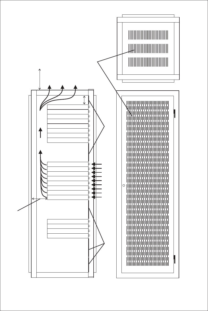
The cooling airflow for the subrack enters through the front panel and exits
at the rear. For optimum thermal performance, the heated air that passes
through a base station must never be allowed to re-enter the air-intakes on
the front panel. Any space at the front of the cabinet not occupied by
equipment should be covered by a blanking panel. See Figure 5.1 on
page 41.
Equipment installation should observe the following guidelines:
■The recommended maximum number of subracks in a 38U cabinet is
five, as illustrated in Figure 5.1 on page 41.
■Any space at the front of the cabinet not occupied by equipment should
be covered by a blanking panel. Refer to Figure 5.1 on page 41.
■Subrack placement in the cabinet should include a 2U gap at the top of
the cabinet.
■To allow enough cooling airflow through a cabinet-mounted base
station, the cabinet should allow for 50 cu.ft/min for each subrack
(0.024 cu.m/s).
■To ensure adequate ventilation, the cabinet should have a vent at the top
with an area of approximately 23in² (150cm²) per subrack, or a similar
area of ventilation at the rear of the cabinet behind each subrack.
■The maximum ambient temperature at the base station front panels must
not exceed +140°F (+60°C).
TB7300 Installation and Operation Manual Installation 41
© Tait Limited November 2017
Figure 5.1 Typical cabinet ventilation requirements
bventilation slots dairflow entry
cblanking panels eairflow exit
20cm
(8in)
2U
t10cm
(t4in)
side view front view
top view
c
c
d
e
b
42 Installation TB7300 Installation and Operation Manual
© Tait Limited November 2017
5.2 Unpacking the Equipment
Unpacking the
Base Station
The base station is packed in a strong corrugated cardboard carton with top
and bottom cushions.
1. Cut the tape securing the flaps at the top of the carton and fold them
flat against the sides.
2. Rotate the carton carefully onto its side and then onto its top,
ensuring that none of the flaps are trapped underneath.
3. Slide the carton upwards over the cushions and lift it away. Remove
the cushion from the bottom of the base station.
4. Lift the base station clear of the remaining cushion.
Disposal of
Packaging
If you do not need to keep the packaging, we recommend that you recycle
it according to local recycling methods. The cushions are CFC- and HCFC-
free and may be burnt in a suitable waste-to-energy combustion facility, or
compacted in landfill.

TB7300 Installation and Operation Manual Installation 43
© Tait Limited November 2017
5.3 Identifying the Equipment
You can identify the model and hardware configuration of the TB7300 by
referring to the product code printed on a label at the rear of the base
station. The meaning of each character in the product code is explained in
the table below.
This explanation of product codes is not intended to suggest that any
combination of features is necessarily available in any one product.
Consult your regional Tait office for more information regarding the
availability of specific models and options.
Product Code Description
TB73XX-XXXX-XXXX-XXXX-10 10 = single 40/50W base station/repeater
TB73XX-XXXX-XXXX-XXXX-10 Frequency Band
B3 = 148 MHz to 174MHz
H3 = 470MHz to 520MHz
H5 = 400 MHz to 470 MHz
TB73XX-XXXX-XXXX-XXXX-10 B = 40/50W
TB73XX-XXXX-XXXX-XXXX-10 0 = default
TB73XX-XXXX-XXXX-XXXX-10 0 = default
TB73XX-XXXX-XXXX-XXXX-10 0 = 13.8VDC (nominal) input
TB73XX-XXXX-XXXX-XXXX-10 0 = default
TB73XX-XXXX-XXXX-XXXX-10 Feature License
00 = None [Default: Analog (TBAS301)]
AC = DMR Express SFE License with TDMA
operation (TBAS302)
AD = DMR Access SFE License with TDMA
operation (TBAS303)
AE = DMR conventional (TBAS304)
TB73XX-XXXX-XXXX-XXXX-10 10 = default

44 Installation TB7300 Installation and Operation Manual
© Tait Limited November 2017
5.4 Initial Setting Up
Before putting the base station into service, you may want to carry out
some basic functional testing, configuration, and tuning (if required). This
section provides an overview of these procedures:
■checking that the base station powers up correctly
■checking the basic functionality of the base station by using the tests
available in the web interface
■customizing the configuration for the intended installation and
verifying that the configuration is correct
■changing the root password
■tuning the base station, if required
5.4.1 Confirming Operation
Notice The RF output must be connected to a suitable attenuator or
dummy load. Do not remove the load while the PA is transmitting as
this may damage the PA output stage.
Applying Power 1. Apply power to the TB7300.
2. Check that the base station powers up correctly:
All LEDs turn on initially, then the transmit and receive LEDs turn
off, leaving the green power LED on, and the red alarm LED flash-
ing. The alarm LED will turn off when the base station has finished
its start-up sequence.
Functional Tests The following table provides an overview of the tests available using the
web interface. Refer to the base station Help for full details of these tests.
Test Notes Menu
receiver operation requires a suitable RF source Diagnose > RF Interface > Receiver
transmitter operation requires connection to the
network
Diagnose > RF Interface > Transmitter
ping checks the IP connection to
another device with an IP address
Diagnose > Connection > Network
NTP query checks if the NTP-based time
synchronization is working
TB7300 Installation and Operation Manual Installation 45
© Tait Limited November 2017
5.4.2 Working with Configurations
The Web UI page Tools > Files > Configuration allows you to manage your
base station configuration.
You can:
■Back up a configuration. This stores a snapshot of the base station’s
current configuration. It is advisable to back up the current
configuration before making significant configuration changes.
■Upload a configuration. This copies a configuration from your
computer to the base station. You can develop a master configuration
and upload it to all the base stations in the network.
■Restore a configuration. This activates the selected configuration after
making it compatible with the current software. You can restore
configurations that have been backed up on the base station.
■Download a configuration. This copies the selected configuration to
your computer so that you can store it.
5.4.3 Customizing the Configuration
The following steps provide an overview of the process used to configure
the base station with the settings it needs. Refer to the Help for detailed
information.
1. Log in to the base station (refer to “Connecting Your PC to the Base
Station” on page 24 for more details).
2. Select ‘Configure.’ The base station has many different settings that
can be configured before it is put into operation, such as:
■channel configurations
■alarm control and SNMP agent
■network interfaces
■quality of service
■CWID
■miscellaneous items such as NTP and package servers
3. Make the changes needed in each form and click, ‘Save.’ All
changes made in the form will only be applied when the form is
saved.
Notice Before making changes, you should save the configuration to
your PC or network; this provides a baseline which can be restored to
the base station if the configuration information becomes lost or cor-
rupted.
You should also back up the configuration before downgrading to a dif-
ferent software release. Note that if you downgrade and then upgrade
software, configuration values for new features may reset to default.

46 Installation TB7300 Installation and Operation Manual
© Tait Limited November 2017
5.4.4 Restricted Port Numbers
Certain configuration settings in the base station’s web interface require
you to enter a port number (for example, the trunking interface).
Two ranges of port numbers are unavailable for use with the base station.
The web interface will prevent you from entering a number from these
ranges, as explained below.
5.4.5 Changing the Root Password
Notice The following procedure can be carried out only if secure
shell access (SSH) is enabled. Secure shell access to the base station is
disabled by default from version 1.35 onwards. To enable SSH, select
Tools > Settings > Secure shell and click ‘Start’.
The root password to the Linux operating system of the base station is a
possible security risk. The equipment is delivered with a default password
that is well known. Knowledge of the password could be used to render the
equipment inoperable, for example, by deleting files. If you are concerned
about the security risk that this poses, change the password. If Tait provides
support services, they will likely need to know the password.
Notice If you change the password and then lose it, the equipment
must be returned to Tait. Make sure that you store the password securely
and do not lose it.
To change the root password, follow these steps.
1. Log in from your PC to the base station using SSH client software
such as PuTTY. The username is root and the default password is
k1w1.
2. At the # prompt, enter the command passwd.
3. Follow the on-screen instructions.
4. Record the password in a secure location.
Tait networks are deployed with default weak passwords. For the sake
of security, Tait strongly recommends changing the default password
where applicable.
Restricted Port Numbers Details
0 – 1023 The “well-known ports”, commonly used by other devices in a
network. Using a port number in this range could cause
compatibility problems with other devices.
12000 – 14999 Reserved for internal use in the base station. Using a port number
in this range could cause the base station to malfunction.
TB7300 Installation and Operation Manual Installation 47
© Tait Limited November 2017
5.4.6 Tuning the Receiver
Before the base station is installed on site, you may need to tune the
receiver front end. The receiver front end requires tuning if the receive
frequency is shifted more than 2MHz away from the previously set
frequency, or the RSSI level of the new frequency is more than 1dB lower
than the RSSI level of the previously set frequency. Manual tuning is not
required for the H5 (400MHz to 470MHz) model.
The receiver in the B-band base station covers one of the following
frequency bands, depending on the model:
■B3 - 148 to 174MHz
Each of these bands is split into 2 sub-bands:
■B3 - 148 to 159MHz and 159 to 174MHz
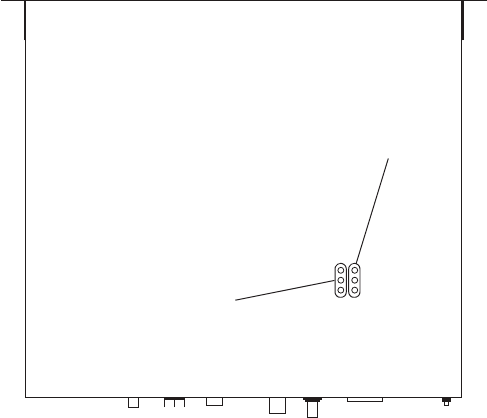
Each sub-band has its own helical filter (shown in Figure 5.2 below) which
is electronically switched in or out of circuit depending on the frequency
programmed into the base station. The bandwidth of these helical filters is
approximately ±1.5MHz.
Figure 5.2 Identifying the B-band receiver front end helical filters
B3: 148 to 159MHz
B3: 159 to 174MHz
48 Installation TB7300 Installation and Operation Manual
© Tait Limited November 2017
To check the RSSI level and tune the receiver front end (if required), follow
these steps:
1. Place the base station on its side or upside down to allow access to
the holes on the base to tune the helical filters.
2. Log in to the TB7300 and select Monitor > Interfaces > RF Interface.
For information on connecting directly to the base station, refer to
“Connecting a Networked PC to a Base Station” on page 25.
3. Feed a signal at the currently tuned receive frequency and at a level
of –80dBm into the RF input. Check that the RSSI reading on the
RF Interface page is –80dBm ±1dB.
4. Set the TB7300 to the new receive frequency.
5. Change the RF input signal to the new receive frequency at
–80dBm. Check that the RSSI reading is –80dBm ±1dB. If it is, the
receiver front end does not require tuning. If it is not, go to the next
step.
6. Using the Johanson tuning tool1, adjust the correct helical filter for
the new frequency (as shown in Figure 5.2) to obtain a peak RSSI
reading. This reading should be within 1dB of the reading at the
previous frequency.
Adjust the center resonator of the filter first, followed by the two
outer resonators (in any order). Each resonator should require
approximately the same amount of adjustment when tuning.
A change in frequency of 5MHz requires approximately one turn of the
tuning slug. If tuning to a lower frequency, turn the slug clockwise; for
a higher frequency, turn the slug anti-clockwise.
7. Change the RF input signal and the receive frequency to 0.5MHz
above and below the required frequency and check that the RSSI
reading does not drop by more than 0.5dB from the reading at the
required frequency.
8. Recalibrate the RSSI at the new frequency (Calibrate > Calibrate >
RSSI).
If you wish to confirm the accuracy of the tuning procedure, carry out a
sensitivity measurement at the new frequency.
1. Included in the TBA0ST2 tool kit. Also available separately as part num-
ber 937-00013-00.
TB7300 Installation and Operation Manual Installation 49
© Tait Limited November 2017
5.5 Installing the Base Station on Site
5.5.1 Base Stations for Trunked Systems
When installing base stations that are part of a trunked system, it is
important to observe good site engineering rules. This is especially true
when the channels are combined into a single antenna.
If possible, the RF planner should avoid frequency plans in which the Rx
to Tx spacing is an exact multiple of the trunked channel spacing, thus
forcing Tx intermodulation products to fall outside the Rx channels.
Cables and antennas should be of high quality. Solid shield heliax cables
are best, but if braided shield cables must be used for short distances, their
braids must be silver-plated. Isolators must be used at all transmitter
outputs.
When the outputs of more than one transmitter are combined, their voltages
add, and the resulting peak envelope power is not simply the sum of their
powers, but is equal to the power of one of them multiplied by the square
of the number of sources. Cables, components, and hardware must be rated
to withstand the peak envelope power.
During the commissioning process, all transmitters should be activated
together using a diagnostic test tone, while the receiver RSSI is monitored.
There should be no discernible increase in RSSI while the transmitters are
active.
5.5.2 Equipment Required
It is beyond the scope of this manual to list every tool that an installation
technician should carry. However, the following tools are specifically
required for installing the base station:
■Philips #2 tip screwdriver used to connect the DC power cables to the
DC power terminals
■Pozidriv PZ3 screwdriver for the M6 screws used to secure the tray to
the cabinet in Tait factory-assembled systems
■8mm spanner for the M5 nut on the ground connector
You can also obtain the TBA0ST2 tool kit from your regional Tait office.
It contains the basic tools needed to install, tune, and service the base
station.
50 Installation TB7300 Installation and Operation Manual
© Tait Limited November 2017
5.5.3 Mounting the Base Station
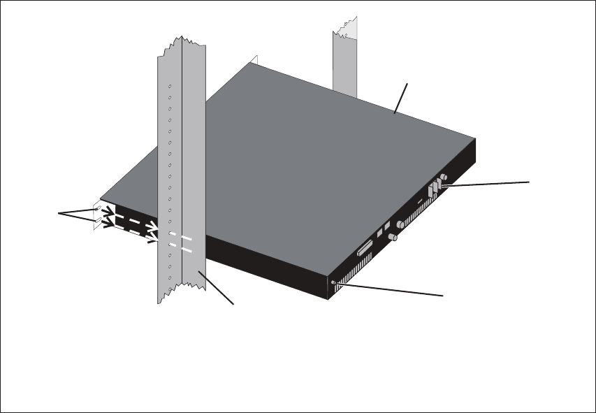
1. Fit the base station into the cabinet or rack and secure it firmly with
an M6 (or 0.25in if using the imperial system) screw, flat and spring
washer in each of the four main mounting holes b, as shown in
Figure 5.3 on page 50.
2. The base station can be wall-mounted by rotating the front mounting
brackets and fitting the optional rear brackets (TBBA03-01). When
the base station is wall-mounted ensure the airflow is from bottom to
top (front panel mounted down) or side to side.
3. For transport or in installations subject to vibration, the base station
should be supported at the rear using a transit bracket
(Tait recommends using the TBBA03-04 transit bracket).
Cabling Tait recommends you route all cables to and from the base station along the
side of the cabinet so the cooling airflow is not restricted.
Cables should be well supported so that the connectors or terminals on the
base station and on the ends of the cables do not have to support the full
weight of the cables.
Cables must be routed so that they do not restrict the air outlets at the rear
of the base station.
Figure 5.3 Base station mounting points
bmain mounting holes eground point
cbase station frack frame
dDC power connector
fE
c
b
D
TB7300 Installation and Operation Manual Installation 51
© Tait Limited November 2017
5.6 Connecting the Base Station
This section provides information relevant to the task of connecting up the
various inputs and outputs of the base station.
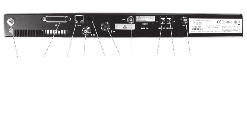
5.6.1 Connection Overview
External connections are all located at the rear of the base station. See
Figure 5.4 below.
Figure 5.4 Base station inputs and outputs
bground connector gRF output
csystem interface connector h1PPS input connector
dEthernet interface connector i-VDC input
eRF input j+VDC input
fserial RS-232 connector 1) External reference input
bcdefghij1)
52 Installation TB7300 Installation and Operation Manual
© Tait Limited November 2017
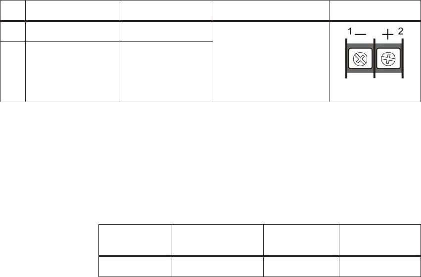
5.6.2 Connecting DC Power
The base station is designed to accept a nominal 13.8V DC, with negative
ground.
Notice Any mains power supply used to power the base station is
required to meet the isolation separation for reinforced insulation of
3000Vrms or 4242VDC.
The DC power connector at the rear of the base station is a heavy-duty M4
screw terminal connector suitable for many forms of connection.
You must connect the DC supply from the battery to the base station via a
readily accessible disconnect device such as a fuse or DC-rated circuit
breaker with the appropriate rating, as shown in the table below.
The DC input leads should be of a suitable gauge to ensure less than 0.2V
drop at maximum load over the required length of lead. Use only flexible
copper cables.
Terminate the DC input leads with a suitable crimp connector for attaching
to the M4 screws of the DC power connector.
Pin Signal Name Signal Type Notes External View
1 ground input The maximum current for
each band:
■B band: 50W 9.6A
Typical
■H band: 40W 8.1A
Typical
2 13.8VDC input
Nominal
Supply Voltage
Input Voltage
Range
Circuit Breaker/
Fuse Rating
Recommended
Wire Gaugea
a. For a length of 1.5m to 2m (5ft to 6.5ft) (typical).
13.8VDC 11.8VDC to 14.4VDC 20A 12AWG / 3.3mma
TB7300 Installation and Operation Manual Installation 53
© Tait Limited November 2017
5.6.3 Connecting RF
Notice Do not remove the load from the base station while it is trans-
mitting as this may damage the PA output stage. Before disconnecting
RF cables, put the base station into ‘Offline’ mode to prevent any trans-
missions.
The RF input to the base station is via the marked BNC connector on the
rear panel. The RF output is via the N-type connector on the rear panel
(refer to Figure 5.4 on page 51).
Cables and antennas should be of high quality. Solid shield heliax type
cables are best, but if braided shield cables must be used for short distances,
their braids must be silver-plated.
Recommendations
for Installing the
Base Station
We recommend the following installation procedures, which should protect
the PA from damage under all but the most extreme operating conditions
1. Do not connect the base station directly to the antenna. Fit an isola-
tor or duplexer between the base station and the load. Fit the isolator
as close as possible to the RF output connector on the base station.
Do not connect any switching equipment between the isolator and
the base station, unless the switch cannot operate while there is RF
present (i.e. the base station is transmitting).
2. Fit a surge suppressor to the antenna cabling where it enters the
building.
3. Inspect all cables and equipment connected to the base station for
defects.
A broken antenna or ice is unlikely to cause damage to the PA.
Explanation The circuit design of the PA protects the circuitry from high VSWR. This
makes it difficult to damage the RF power device by keying the PA into a
mismatched load, or if the load deteriorates over even a short period of time
(milliseconds).
However, it is possible to damage the device if all the following conditions
happen at the same time:
■there is a step change in the PA load (for example, the load is removed)
■the PA is transmitting
■the feed line loss between the PA and the mismatch is <1dB
The effect of such conditions is variable: some devices will not be
destroyed, and some may fail after repeated load interruptions.
54 Installation TB7300 Installation and Operation Manual
© Tait Limited November 2017
5.6.4 Connecting an External Frequency Reference
An external reference frequency is not normally required for B band.
However, an external reference can be used when you need to maximize
the range of the base station. The external reference frequency can be
10MHz or 12.8MHz, with an input level of 300mVpp to 5Vpp. The
stability of this reference should be better than 100 parts per billion. The
base station automatically detects the frequency of the external reference
and configures itself accordingly.
If an external reference is required, enable the external reference “external
reference absent” alarm (Configure > Alarms > Control).
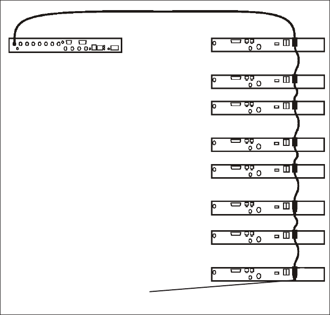
Use a 50: coaxial cable (RG58 or RG223) to connect the external
reference to the base station’s external reference frequency input. You can
daisy-chain up to eight base stations using T-junctions. The maximum
overall cable length is 30m. Terminate the last connection (including single
base stations) with a 50: load.
Figure 5.5 Daisy-chaining an external frequency reference input
maximum of eight base
station loads on one
frequency reference output
maximum overall cable
length is 30m
50: termination
TB7300 Installation and Operation Manual Installation 55
© Tait Limited November 2017
5.6.5 Connecting a 1PPS Source
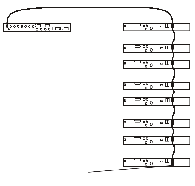
A 1PPS signal is required for simulcast base stations. Use a 50ȍ coaxial
cable (RG58 or RG223) to connect the source to the base station’s 1PPS
input. You can daisy-chain up to eight base stations using T-junctions. We
recommend that the cable length between the first and last load is kept to a
minimum. This will reduce any propagation variation between base
stations. The maximum overall cable length is 30m. Terminate the last
connection with a 50ȍ resistor, otherwise reflections of the 1PPS pulse
may occur.
Notice If 1PPS is used, then 1PPS and NTP must both be derived
from the same time base. Normally this will be a GPS disciplined
source.
Figure 5.6 Daisy-chaining a 1PPS input
50: termination
The longest length of cable must be
between the source and the first base
station
Use short lengths of cable
between each base station
Maximum of eight base station
loads on one 1PPS output
56 Installation TB7300 Installation and Operation Manual
© Tait Limited November 2017
5.6.6 Ethernet Connection
The RJ-45 socket on the reciter’s rear panel provides the 10 BASE-T or
100 BASE-T Ethernet connection to the other devices in the network. Use
a Cat-5 cable to connect this socket to the Tait Network via a router or
switch.
The Web UI allows you to set the Ethernet port speed auto-negotiation to
10/100 Mbit/s or to negotiate a maximum 10 Mbit/s. Tait recommends that
you keep the port speed at the factory default setting of 10 Mbit/s. The
reciter hardware and software are scaled to meet the performance
requirements of processing multiple voice streams along with supervisory
control and management communications. 10 Mbit/s is ample for those
requirements. The 10/100 Mbit/s setting is provided for compatibility
reasons, but it is possible under high traffic conditions at 100 Mbit/s for
traffic arriving at the reciter at the full rate within a small timing window
to overflow internal buffers and therefore suffer packet loss. If you set the
port speed to 100 Mbit/s and observe QoS lost packet alarms, then review
your Ethernet port speed settings.
With the port speed at 10 Mbit/s it is particularly important to set the voice
QoS on the reciter port of your site router or switch to a strict priority queue
policy - which is the same policy that you should also be setting for your
site link ports. The default QoS settings restrict the voice bandwidth to 1/
25th of the port speed which is smaller than the required bandwidth for
typical systems at 10 Mbit/s.
If necessary, refer to “Ethernet Connector” on page 60 for a list of Ethernet
connection pin allocations.
TB7300 Installation and Operation Manual Installation 57
© Tait Limited November 2017
5.6.7 Connecting General Purpose Inputs
The base station has a number of general purpose inputs and outputs.
These are connected via the 25-way D-range on the rear panel.
The pin allocations for the D-range connector are given in the following
table. Not all pins are used in this release of the base station.
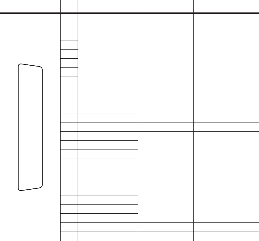
Pin Signal Name Signal Type Notes
1 not used reserved for future use
2
3
4
5
6
7
8
9
10
11 digital in 1 input 5V TTL logic
active low
12 digital in 2
13 +5.2VDC output power output maximum current 200mA
14 digital in 3 input 5V TTL logic
active low
15 digital in 4
16 digital in 5
17 digital in 6
18 digital in 7
19 digital in 8
20 digital in 9
21 digital in 10
22 digital in 11
23 digital in 12
24 not used reserved for future use
25 ground ground
external view
B
C
D
E
F
G
H
I
J
1)
1!
1@
1#
1$
1%
1^
1&
1*
1(
2)
2!
2@
2#
2$
2%