Tait TEL0036 Mobile Transceiver User Manual 429 20000 06 p65

Tait Limited Mobile Transceiver 429 20000 06 p65
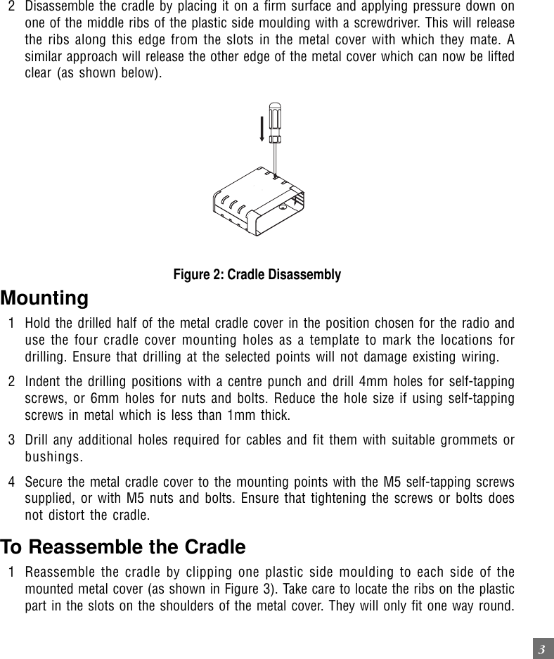
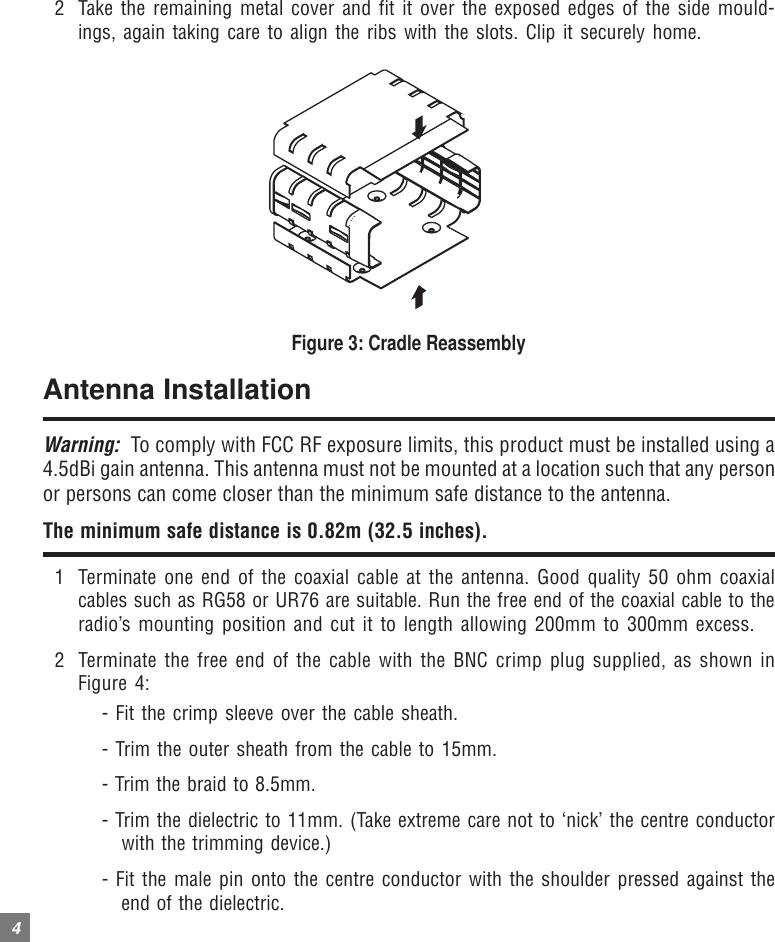
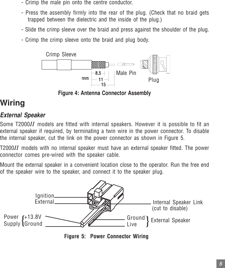
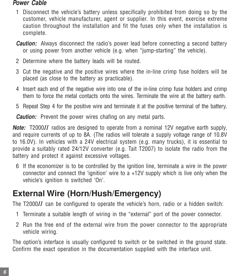
Installation Guide

T2000 SERIES IIINSTALLATIONGUIDET2000II
TAIT ELECTRONICS LIMITEDSoftware licence agreementThis legal document is an Agreement between you, (the “Licencee”) and Tait Electronics Limited (“Tait”).  By opening this product package and/or using theproduct you agree to be bound by the terms of this Agreement. If you do not agree to the terms of this Agreement, do not open the product package andimmediately return the unopened product package to Tait.  If you open the product package that will be deemed to be acceptance of the terms of this licenceagreement.LicenceIn consideration of the payment of the Licence Fee which forms part of the price you paid for products you acquired from Tait or its subsidiary or agent (the“products”) and our willingness to be bound by the terms of this agreement, Tait grants to you as Licencee the non-exclusive right to use the copy of a Taitsoftware program included in the products, (the “Software”).In particular the Licencee may use the program on a single machine and if the software is supplied on a diskette, the licensee may:(a)   copy the program into any machine readable or printed form for backup purposes in support  of your use of the program on the single machine(Certain programs, however, may include mechanisms to  limit or inhibit copying.  They are marked “copy protected”), provided the copyrightnotice must be reproduced and included on any such copy of the Software.(b)   Merge it into another program for your use on the single machine. (Any portion of this program merged into another program will continue tobe subject to the terms and conditions of this Agreement.);The Licencee may not duplicate, modify, reverse compile or reverse assemble the Software in whole or part.Title to softwareThis agreement does not constitute a contract of sale in relation to the Software supplied to the Licencee.  Not withstanding the Licencee may own the magneticor other physical media on which the Software was originally supplied, or has subsequently been recorded or fixed, it is a fundamental term of this Agreementthat at all times title and ownership of the Software, whether on the original media or otherwise, shall remain vested in Tait or third parties who have grantedlicences to Tait.Term and terminationThis Licence shall be effective until terminated in accordance with the provisions of this Agreement.  The Licencee may terminate this Licence at any time bydestroying all copies of the Software and associated written materials.  This Licence will be terminated  automatically and without notice from Tait in the event thatthe Licencee fails to comply with any term or condition of this Agreement.  The Licencee agrees to destroy all copies of the Software and associated writtenmaterials in the event of such termination.Limited warrantyThe Software is supplied by Tait and accepted by the Licencee “as is” without warranty of any kind either expressed or implied, including but not being limited toany implied warranties as to merchantability or fitness for any particular purpose.  The entire risk as to the quality and performance of the Software vests in theLicencee. Should the Software prove to be defective, the Licencee (and not Licensor or any subsidiary or agent of the Licensor) shall assume the entire cost ofall necessary servicing, repair or correction. Tait does not warrant that the functions contained in the Software will meet the Licencee’s requirements or that theoperation of the Software will be uninterrupted or error free.  However Tait warrants that the diskettes if any on which the Software is supplied to the Licenceeshall be free from defects in material and workmanship under normal use and service for a period of ninety (90) days from the date of delivery to the Licencee.Exclusion of liabilityTait’s entire liability and the Licencee’s exclusive remedy shall be:1. The replacement of any diskette not meeting Tait “limited warranty” and which is returned to Tait or an authorised agent or subsidiary of Tait with acopy of the Licencee’s purchase receipt; or2. If a diskette is supplied and if Tait is unable to deliver a replacement diskette which is free from defects in material or workmanship, the Licencee mayterminate this Agreement by returning the Software to Tait.3. In no circumstances shall Tait be under any liability to the Licencee, or any other person whatsoever, for any direct or consequential damage arisingout of or in connection with any use or inability of using the Software.4. Tait warrants the operation of the Software only with the operating system for which it was designed.  Use of the Software with an operating systemother than that for which it was designed  may not be supported by Tait, unless otherwise expressly agreed by Tait.GeneralThe Licencee confirms that it shall comply with the provisions of law in relation to the Software.Law and jurisdictionThis Agreement shall be subject to and construed in accordance with New Zealand law and disputes between the parties concerning the provisions hereof shallbe determined by the New Zealand Courts of Law.  Provided however Tait may at its election bring proceedings for breach of the terms hereof or for theenforcement of any judgement in relation to a breach of the terms hereof in any jurisdiction Tait considers fit for the purpose of ensuring compliance with theterms hereof or obtaining relief for breach of the terms hereof.No DealingsThe Licencee may not sublicense, assign or transfer the licence or the program except as expressly provided in this Agreement.  Any attempt otherwise tosublicense, assign or transfer any of the rights, duties or obligations hereunder is void.No Other TermsThe Licencee acknowledges that it has read this agreement, understand it and agree to be bound by its terms and conditions.  The Licencee further agrees thatthis is the complete and exclusive statement of the agreement between it and Tait in relation to the Software which supersedes any proposal or prior agreement,oral or written and any other communications between the Licencee and Tait relating to the  Software. (LS-589)
ContentsComponents of the T2000II Radio Kit ..................................................................... 1Recommended Installation Tools ........................................................................... 1Installation of your Radio .................................................................................... 2Installation Planning ........................................................................................................................ 2To Disassemble the Cradle ............................................................................................................... 2Mounting ......................................................................................................................................... 3To Reassemble the Cradle ................................................................................................................ 3Antenna Installation ......................................................................................................................... 4Wiring ............................................................................................................................................. 5External Speaker .............................................................................................................................. 5Power Cable .................................................................................................................................... 6External Wire (Horn/Hush/Emergency) .............................................................................................6Remote Control Head Option ............................................................................................................ 7Microphone Clip .............................................................................................................................. 7Installation Checks ........................................................................................................................... 8
1Components of the T2000II Radio KitThe T2000II Radio kit includes the following parts:lT2000II Radio UnitlMicrophonelComplete Cradlel4 Ohm Speaker (not for internal speaker models)lInstallation Kit: - Two-way hermaphroditic connector (1)- Socket receptacle (2)- 10A 12V Blade fuse (2)- Inline crimp fuse holder (2)- Self tapping screw (4)- Shakeproof washer (4)- Microphone clip kit (1)- Control head mounting bracket (T2020II and T2040II  only)Recommended Installation ToolslPortable DrilllCentre PunchlDrill Bits: 4mm for self-tapping screws, 6mm for nuts and boltsl“Pozidriv” ScrewdriverslBNC Crimp Tool (e.g. Transradio England Duo crimp 894)lIn-line Power Meter capable of measuring forward and reflected power at the operat-ing frequency of the radiolHammerlBNC Antenna Crimp PluglCradle Keys (2)lPower Cable (5m)
2Installation of your RadioInstallation PlanningTo ensure trouble-free, efficient installation, inspect the vehicle and determine how andwhere the antenna, radio and accessories are to be mounted.It is possible to remote-mount the T2020II, T2040II and T2050II models as these havealphanumeric keypads, with the control head separate from the radio chassis. This enablesthe radio to be mounted in a discrete location, e.g. the rear luggage space, with the controlhead mounted in a convenient position for the vehicle’s occupants. See the M2000 servicemanual, available from your Tait dealer, for details of this modification.Occupant’s SafetyCheck that the chosen locations for the radio and accessories do not endanger the vehicleoccupants. Overhead mounting is not recommended, especially without an additionalsafety strap. Check that the radio may be conveniently operated when seat belts are worn.Caution:  To prevent interference with vehicle electronic systems (such as ignition andanti-skid devices), the radio, its antenna and wiring should be mounted away from theseunits and their associated cables.Allow sufficient airflow around the radio to permit adequate cooling. Once you have found asuitable mounting position for the radio, hold it (fitted in the cradle) in the proposed mount-ing position and check there is clearance behind it for the heatsink, cables, etc. Check that theposition provides a large enough flat surface that the cradle will not be distorted.To Disassemble the Cradle1 Remove the radio from its cradle by sliding the plastic key supplied with the radio fullyinto the slot on the left front of the radio unit. The radio will now slide out forwardsfrom the cradle, as shown below:Figure 1: Cradle and KeyCradleRadio unitPlastic key
32 Disassemble the cradle by placing it on a firm surface and applying pressure down onone of the middle ribs of the plastic side moulding with a screwdriver. This will releasethe ribs along this edge from the slots in the metal cover with which they mate. Asimilar approach will release the other edge of the metal cover which can now be liftedclear (as shown below).Figure 2: Cradle DisassemblyMounting1 Hold the drilled half of the metal cradle cover in the position chosen for the radio anduse the four cradle cover mounting holes as a template to mark the locations fordrilling. Ensure that drilling at the selected points will not damage existing wiring.2 Indent the drilling positions with a centre punch and drill 4mm holes for self-tappingscrews, or 6mm holes for nuts and bolts. Reduce the hole size if using self-tappingscrews in metal which is less than 1mm thick.3 Drill any additional holes required for cables and fit them with suitable grommets orbushings.4 Secure the metal cradle cover to the mounting points with the M5 self-tapping screwssupplied, or with M5 nuts and bolts. Ensure that tightening the screws or bolts doesnot distort the cradle.To Reassemble the Cradle1 Reassemble the cradle by clipping one plastic side moulding to each side of themounted metal cover (as shown in Figure 3). Take care to locate the ribs on the plasticpart in the slots on the shoulders of the metal cover. They will only fit one way round.
42 Take the remaining metal cover and fit it over the exposed edges of the side mould-ings, again taking care to align the ribs with the slots. Clip it securely home.Figure 3: Cradle ReassemblyAntenna InstallationWarning:  To comply with FCC RF exposure limits, this product must be installed using a4.5dBi gain antenna. This antenna must not be mounted at a location such that any personor persons can come closer than the minimum safe distance to the antenna.The minimum safe distance is 0.82m (32.5 inches).1 Terminate one end of the coaxial cable at the antenna. Good quality 50 ohm coaxialcables such as RG58 or UR76 are suitable. Run the free end of the coaxial cable to theradio’s mounting position and cut it to length allowing 200mm to 300mm excess.2 Terminate the free end of the cable with the BNC crimp plug supplied, as shown inFigure 4:- Fit the crimp sleeve over the cable sheath.- Trim the outer sheath from the cable to 15mm.- Trim the braid to 8.5mm.- Trim the dielectric to 11mm. (Take extreme care not to ‘nick’ the centre conductor   with the trimming device.)- Fit the male pin onto the centre conductor with the shoulder pressed against the   end of the dielectric.
5- Crimp the male pin onto the centre conductor.- Press the assembly firmly into the rear of the plug. (Check that no braid gets   trapped between the dielectric and the inside of the plug.)- Slide the crimp sleeve over the braid and press against the shoulder of the plug.- Crimp the crimp sleeve onto the braid and plug body.Figure 4: Antenna Connector AssemblyWiringExternal SpeakerSome T2000II models are fitted with internal speakers. However it is possible to fit anexternal speaker if required, by terminating a twin wire in the power connector. To disablethe internal speaker, cut the link on the power connector as shown in Figure 5.T2000II models with no internal speaker must have an external speaker fitted. The powerconnector comes pre-wired with the speaker cable.Mount the external speaker in a convenient location close to the operator. Run the free endof the speaker wire to the speaker, and connect it to the speaker plug.Figure 5:  Power Connector WiringCrimp SleeveMale PinPlugIgnitionExternal Internal Speaker Link(cut to disable)GroundLive }External Speaker+13.8VGround{PowerSupply
6Power Cable1 Disconnect the vehicle’s battery unless specifically prohibited from doing so by thecustomer, vehicle manufacturer, agent or supplier. In this event, exercise extremecaution throughout the installation and fit the fuses only when the installation iscomplete.Caution:  Always disconnect the radio’s power lead before connecting a second batteryor using power from another vehicle (e.g. when “jump-starting” the vehicle).2 Determine where the battery leads will be routed.3 Cut the negative and the positive wires where the in-line crimp fuse holders will beplaced (as close to the battery as practicable).4 Insert each end of the negative wire into one of the in-line crimp fuse holders and crimpthem to force the metal contacts onto the wires. Terminate the wire at the battery earth.5 Repeat Step 4 for the positive wire and terminate it at the positive terminal of the battery.Caution:  Prevent the power wires chafing on any metal parts.Note:  T2000II radios are designed to operate from a nominal 12V negative earth supply,and require currents of up to 8A. (The radios will tolerate a supply voltage range of 10.8Vto 16.0V). In vehicles with a 24V electrical system (e.g. many trucks), it is essential toprovide a suitably rated 24/12V converter (e.g. Tait T2007) to isolate the radio from thebattery and protect it against excessive voltages.6 If the economizer is to be controlled by the ignition line, terminate a wire in the powerconnector and connect the ‘ignition’ wire to a +12V supply which is live only when thevehicle’s ignition is switched ‘On’.External Wire (Horn/Hush/Emergency)The T2000II can be configured to operate the vehicle’s horn, radio or a hidden switch:1 Terminate a suitable length of wiring in the “external” port of the power connector.2 Run the free end of the external wire from the power connector to the appropriatevehicle wiring.The option’s interface is usually configured to switch or be switched in the ground state.Confirm the exact operation in the documentation supplied with the interface unit.
7Remote Control Head OptionThe control head of some T2000II models may be supplied ready for mounting remotelyfrom the radio chassis. In this case the control head should be located away from directsunlight, and the cable connecting it to the radio should be routed away from the antennawith care taken to ensure that the cable will not be subject to damage.If it is necessary to run the cable through a bulkhead or similar obstruction, you mayunplug the cable from the control head as follows:1 Unscrew the rear of the control panel and lift off the rear cover, taking care not to losethe two nuts located on each end.2 Disconnect the red connector from the printed circuit board socket to free the cable.3 Route the cable as required, fitting grommets where necessary to prevent chafing ofthe cable insulation.4 Fit the red connector to the printed circuit board socket – the connector is shaped sothat it can be fitted in the correct orientation only.5 Refit the cable to the cable clamp on the rear cover and slip the two nuts into thereceptacles at each end of the rear cover.6 Refit the rear cover and replace the cover screws, tightening them carefully. Do notovertighten the screws.The control head can now be installed as follows:1 Mount the bracket for the control panel on a flat surface using the self-tapping screwssupplied.2 Place the control head in the bracket, position it for a good viewing angle, and fit the2 screws to secure it in place.Microphone ClipThe microphone clip must be earthed (to the negative supply line) if hookswitch control ofmonitoring, scanning or call termination is to operate. Refer to the radio’s operating in-structions to confirm requirements.Ensure that the microphone clip is mounted in a position where the microphone PTT keycannot be inadvertently activated or jammed on.
8Installation Checks1 Plug the microphone into the socket on the lower left-hand corner of the radio’s frontpanel. Push the cable grommet into the rectangular aperture in the panel.2 Insert the fuses into the power lead.3 Switch on the radio and confirm that it is operational.4 Connect an in-line power meter between the radio and the antenna and measure theforward and reflected power levels. Less than 1W should be reflected for 25W forwardpower. If this is not achieved, check the installation – including antenna length.5 Make a call to another party on the radio (as described in the operating instructions).Tait Electronics has made every effort to ensure the accuracy of information in thismanual. However, Tait Electronics reserves the right to update the radio and / or thismanual without notice.
HEAD OFFICE NEW ZEALANDTait Electronics LtdP.O. Box 1645, ChristchurchPhone : (64) (3) 358-3399   Fax : (64) (3) 358-3636AUSTRALIATait Electronics (Aust) Pty LtdPhone : (61) (7) 3260-7799   Fax : (61) (7) 3260-7990Toll Free : (1800) 07-7112CANADATait Mobile Radio IncPhone : (1) (905) 472-1100   Fax : (1) (905) 472-5300Toll Free : (1) 1-800-890-8248FRANCETait France S.A.R.L.Phone : (33) (1) 41-14-05-50   Fax : (33) (1) 41-14-05-55GERMANYTait Mobilfunk GmbHPhone : (49) (911) 96746-0   Fax : (49) (911) 96746-79HONG KONGTait Mobile Radio (Hong Kong) LtdPhone : (852) 2369 3040   Fax : (852) 2369 3009NEW ZEALANDTait Communications LtdPhone : (64) (3) 348-3301   Fax : (64) (3) 343-0558SINGAPORETait Electronics (Far East) Pte LtdPhone : (65) 471-2688   Fax : (65) 479-7778TAIWANTait Mobile Radio (Taiwan) LtdPhone : (886) 2-731-1290   Fax : (886) 2-711-6351THAILANDTait Mobile Radio LtdPhone : (662) 2676290-2   Fax : (662) 2676293UNITED KINGDOMTait Mobile Radio LtdPhone : (44) (1480) 52255   Fax : (44) (1480) 411996U.S.A.Tait Electronics (USA) IncPhone : (1) (713) 984-8684   Fax : (1) (713) 468-6944Toll Free : 1-800-222-1255Excellence inRadio Communications07/00 IPN: 429-20000-06T2000II

Navigation menu