Tait TEL0049 One way paging transmitters T857-26-1010 & T857-26 User Manual 8c500 a3 bk
Tait Limited One way paging transmitters T857-26-1010 & T857-26 8c500 a3 bk
Tait >
Contents
- 1. Diagram of units
- 2. Installation instructions
- 3. Manual
Installation instructions
M850-00
T856/857 Installation
F2.1
Copyright TEL 31/09/98
2 T856/857 Installation
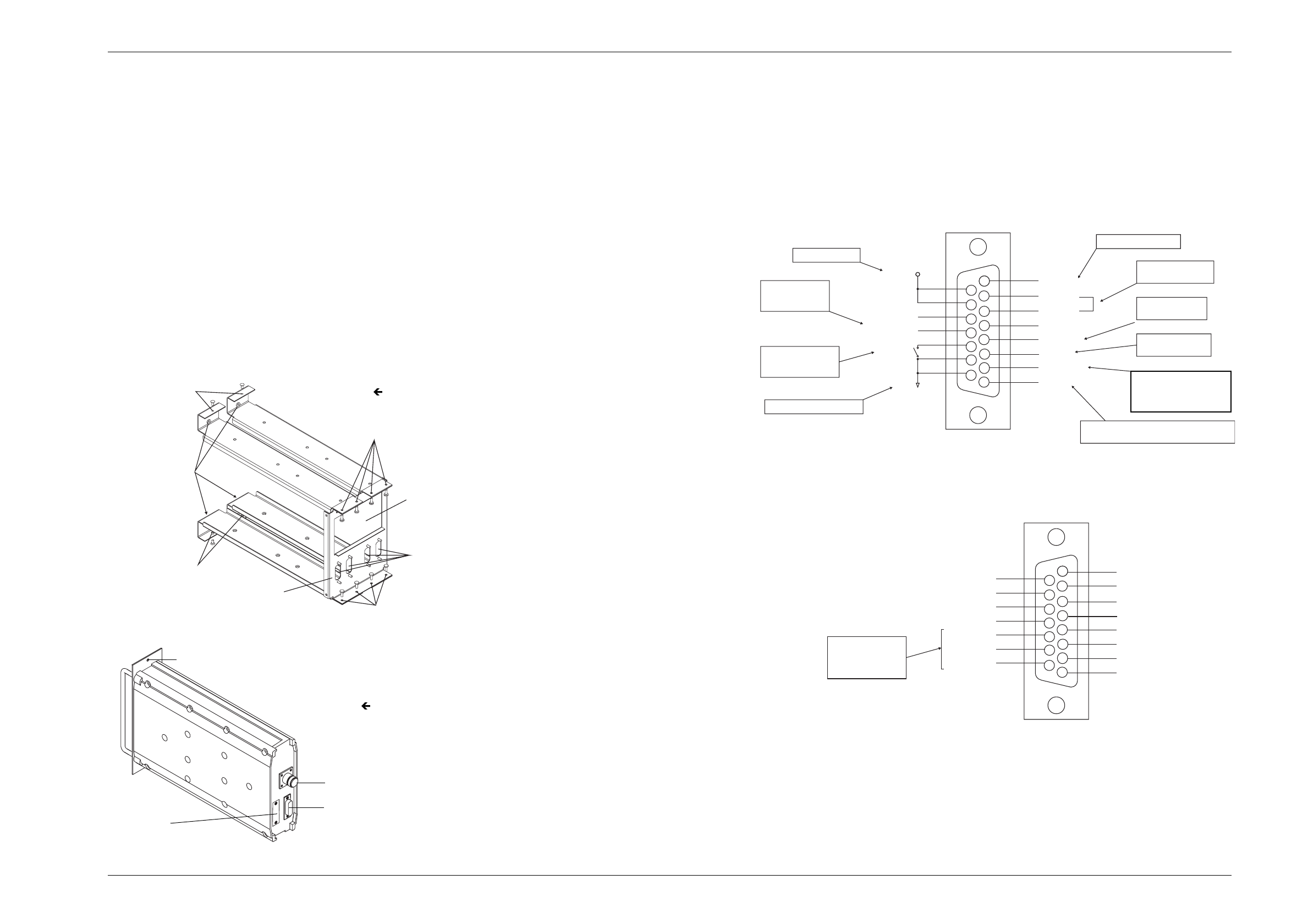
2.1 Rack Mounting
The T856 transmitter and T857 exciter are designed for use in a standard 483mm rack
frame using a Tait T800 Series II guide. The guide is securely mounted to the rack frame
with front and rear retaining screws, and the T856/857 is secured into the guide with
two front panel mounting screws. Figure 2.1 shows a standard, double module guide
which can also be fitted with an optional backplane PCB to locate and mate the rear
D-range connector(s). For more information on available guide kits, refer to the T800
Ancillary Equipment Service Manual or your nearest Tait Dealer or Customer Service
Organisation.
A rear mounted N-type connector is used for RF output on the T856/857, while all DC,
audio and control connections are via the rear mounted D-range connector, D-range 1
(PL100). An additional rear D-range connector (T800-03-0000) can be fitted when
remote multichannel operation, or additional control or low frequency lines are
required (refer to Figure 2.2).
2.2 Rack Wiring
The D-range input and output connections are shown in Figure 2.3 and Figure 2.4.
Ensure that the cables are not subjected to any stresses due to tight bends or incorrect
lengths.
Make sure the RF coax cable to the N-type connector is free from sharp bends or twists.
If access to the rear of the rack frame is restricted, the cable should be long enough to
allow the chassis to be fully withdrawn from the guide.
Figure 2.3 T856/857 D-Range 1 Wiring - Rear View
Figure 2.4 T856/857 D-Range 2 Wiring - Rear View
(standard T800-03-0000 kit)
Note:
Figure 2.4 above shows the standard pin allocations for the T800-03-0000
auxiliary D-range kit. A T800-03 auxiliary D-range kit is also available for
special applications requiring custom internal wiring.
Front Panel
Mounting Holes
Rack Mounting Holes
Rack Mounting Holes
Rack Mounting Holes
Slots For D-Range
Connectors
Rack Mounting Holes
Aperture For RF
Connectors
Optional Backplane PCB
Mounts On Rear Of Guide
N-Type Connector
D-Range Plug
(D-Range 1)
Space For Optional
D-Range Plug
(D-Range 2)
Front Panel Mounting Hole
Figure 2.2 T856/857 Chassis Connectors
Figure 2.1 T800-41-0002 Double Guide Kit
1
2
3
4
5
6
7
8
9
10
11
12
13
14
15
External CTCSS input:
1kHz deviation @150Hz (500mV rms)
To key transmitter:
high impedance
<0.7V = key
High isolation
keying option:
6 to 50V DC To key PA, open
collector
Can be configured as
Audio 1 by internal
link resistors if required
Short together for
normal operation
Sensitivity: -30dBm
External/auxiliary
audio processing
Power supply, -ve earth
10.8 to 16V DC
Line I/P1
CTCSS
Serial Com
Audio 2
Tx Enable
Line I/P4
Line I/P3
Line I/P2
Opto Key +
Opto Key -
+13.8V
Gnd
Tx Key
Can be configured as
Audio 1 by internal link
resistors if required.
Refer to Part I.
Open drain type;
capable of sinking
2.25mA via 2k2Ω;
V max. = 5V
ds
1
2
3
4
5
6
7
8
9
10
11
12
13
14
15
CH_SLCT 0
CH_SLCT 1
CH_SLCT 2
CH_SLCT 3
CH_SLCT 4
CH_SLCT 5
CH_SLCT 6
CH_SLCT 7
GND
TX RELAY DRV
CTCSS DISABLE
SERIAL COM
AUX-OUT 0
AUX-OUT 1
AUX-OUT 2

F2.2
T856/857 Installation
M850-00
29/02/00 Copyright TEL
2.3 Power Supply
If a power supply other than an appropriate Tait model is used, ensure that it is capable
of providing enough current to drive the T800 system and is also free from excessive
ripple or noise.
The system should be protected by the use of appropriately rated fuses in the power
supply.
Note:
It is particularly important when the prime power source is a battery that
fuses be employed in all supply lines.
2.4 Reverse Polarity & Overvoltage Protection
A crowbar diode is fitted to all T856 transmitters and T857 exciters for protection
against connection to a power supply of incorrect polarity. It also provides overvoltage
protection from voltage transients caused by lightning strikes.
Note:
A fuse must be fitted in the power supply line for the diode to provide effec-
tive protection.
M850-00
T858/859 Installation
F3.1
Copyright TEL 31/01/99
3 T858/859 Installation
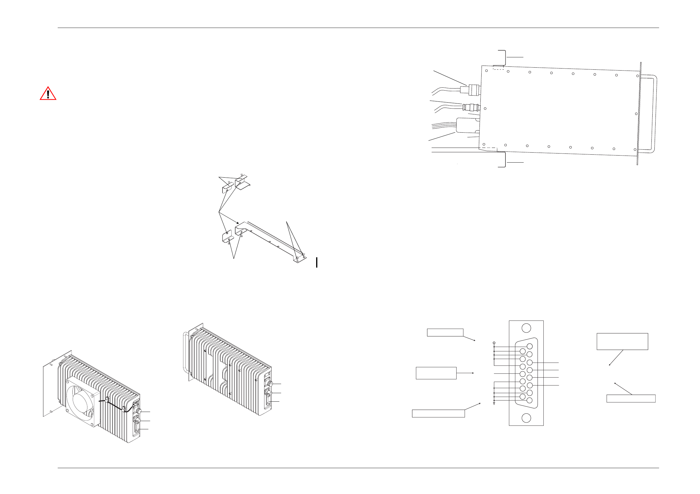
3.1 Rack Mounting
Caution:
If you require continuous operation of the T858, leave the rack module
position immediately adjacent to the finned heatsink empty. There
should be adequate airflow over the fins at all times. Extra airflow can
be provided by fitting an auxiliary fan kit such as the T800-19-0010
(refer to the T800 Ancillary Equipment Service Manual or your nearest
Tait Dealer or Customer Service Organisation for more details).
The T858 and T859 PAs are designed
for use in a standard 483mm rack frame
using Tait T800 Series II guide rails.
The guide rails are securely mounted to
the rack frame with front and rear
retaining screws, and the PA is secured
into the guide with two (T858) or four
(T859) front panel mounting screws.
Figure 3.1 shows the standard, double
width guide designed for use with the
T859, while Figure 3.3 shows how the
PA can be latched in the extended posi-
tion. For more information on availa-
ble guide kits, refer to the T800
Ancillary Equipment Service Manual
or your nearest Tait Dealer or Customer
Service Organisation.
Figure 3.1 T800-45-0001 PA Guide Kit
The PA rear panel has three connectors: a BNC for RF input (from an adjacent T857
exciter), an N-type for RF output and a D-range for all DC, audio and control connec-
tions (refer to Figure 3.2).
Figure 3.2 T858/859 Chassis Connectors
Figure 3.3 T858/859 PA In Latched Position
Note:
You will need appropriate extension leads if you wish to carry out any
adjustment procedures with the PA withdrawn from the rack in the latched
position. Alternatively, disconnect and withdraw the PA and reconnect it
behind the rack.
3.2 Rack Wiring
The D-range input and output connections are shown in Figure 3.4. Ensure that the
cables are not subjected to any stresses due to tight bends or incorrect lengths.
Make sure the RF coax cables to the N-type and BNC connectors are free from sharp
bends or twists. If access to the rear of the rack frame is restricted, the cables should be
long enough to allow the chassis to be fully withdrawn from the guide.
Figure 3.4 T858/859 D-Range Wiring - Rear View
Front Panel
Mounting Holes
Rack Mounting
Holes
Rack Mounting
Holes
Rack Mounting Holes
N-Type Connector
BNC Connector
D-Range Connector
N-Type Connector
BNC Connector
D-Range Connector
T858
T859
RF Output
RF Input
D-range
Top Rail
Bottom Rail
1
2
3
4
5
6
7
8
9
10
11
12
13
14
15
Normally low, float
on alarm conditions.
500mA sink capability.
Pull low to enable
alarm outputs
Power supply, -ve earth
Will drive a coil meter
10.8 to 16V DC
Reverse Power Metering
Forward Power Metering
Reverse Power Alarm
Forward Power Alarm
Tx Key
+13.8V
Gnd

F3.2
T858/859 Installation
M850-00
29/02/00 Copyright TEL
3.3 Power Supply
If a power supply other than an appropriate Tait model is used, ensure that it is capable
of providing enough current to drive the T800 system and is also free from excessive
ripple or noise.
The system should be protected by the use of appropriately rated fuses in the power
supply.
Note:
It is particularly important when the prime power source is a battery that
fuses be employed in all supply lines.
Caution:
Connect the power supply directly to the PA, and not via connector
blocks. This will avoid overheating of connector blocks that are not of
the correct current rating.
3.4 Reverse Polarity & Overvoltage Protection
A crowbar diode is fitted to all T858/859 PAs for protection against connection to a
power supply of incorrect polarity. It also provides overvoltage protection from voltage
transients caused by lightning strikes.
Note:
A fuse must be fitted in the power supply line for the diode to provide effec-
tive protection.