Tait TEL0055 mobile transceiver User Manual Installation Guide
Tait Limited mobile transceiver Installation Guide
Tait >
Contents
Installation Guide

12 T2000 Installation Guide
CORPORATE HEAD OFFICE
NEW ZEALAND
Tait Electronics Ltd
P.O. Box 1645, Christchurch
Phone : (64) (3) 358-3399 Fax : (64) (3) 358-0340
AUSTRALIA
Tait Electronics (Aust) Pty Ltd
Phone : (61) (7) 3865-7799 Fax : (61) (7) 3865-7990
Toll Free : (1-300) 304-344
E-mail: australia@taitworld.com
CANADA
Tait Mobile Radio Inc
Phone : (1) (905) 472-1100 Fax : (1) (905) 472-5300
Toll Free : (1) 1-800-890-8248
E-mail: canada@taitworld.com
Tait Latin America
Phone : (1) (305) 260-9900 Fax : (1) (305) 260-9209
E-mail: latinamerica@taitworld.com
NEW ZEALAND
Tait Communications Ltd
Phone : (64) (3) 348-3301 Fax : (64) (3) 343-0558
E-mail: newzealand@taitworld.com
USA
Tait Electronics (USA) Inc
Phone : (1) (713) 984-8684 Fax : (1) (713) 468-6944
Toll Free : (1-800) 222-1255
E-mail: usa@taitworld.com
TAIT EUROPE
Regional Head Office
UNITED KINGDOM
Tait Europe Ltd
Phone : (44) (1480) 52255 Fax : (44) (1480) 411-996
E-mail: unitedkingdom@taitworld.com
FRANCE
Tait France S.A.R.L.
Phone : (33) (1) 41-14-05-50 Fax : (33) (1) 41-14-05-55
E-mail: france@taitworld.com
GERMANY
German Office
Phone : (49) (911) 2870-7064/7160
Fax : (49) (911) 2870-7077
E-mail: germany@taitworld.com
TAIT NORTH ASIA
Regional Head Office
HONG KONG
Tait Mobile Radio (Hong Kong) Ltd
E-mail: hongkong@taitworld.com
Phone : (852) 2369-3040 Fax : (852) 2369-3009
BEIJING
Tait Mobile Radio (Hong Kong) Ltd
Phone : (86) 10-6510-2680 Fax : (86) 10-6510-2686
E-mail: beijing@taitworld.com
TAIWA N
Tait Mobile Radio (Taiwan) Ltd
Phone : (886) 2-2731-1290 Fax : (886) 2-2-711-6351
E-mail: taiwan@taitworld.com
TAIT SOUTH EAST ASIA
Regional Head Office
SINGAPORE
Tait Electronics (Far East) Pte Ltd
Phone : (65) 471-2688 Fax : (65) 479-7778
E-mail: singapore@taitworld.com
THAILAND
Tait Mobile Radio Ltd
Phone : (662) 267-6290 Fax : (662) 267-6293
E-mail: thailand@taitworld.com
Excellence in
Radio Communications
T2000 Installation Guide
T2000
Installation Guide

2T2000 Installation Guide
T2000 Installation Guide 11
3. Route the cable as required, fitting grommets where necessary to prevent chafing of the cable
insulation.
4. Fit the red connector to the printed circuit board socket – the connector is shaped so that it can be
fitted in the correct orientation only.
5. Refit the cable to the cable clamp on the rear cover and slip the two nuts into the receptacles at
each end of the rear cover.
6. Refit the rear cover and replace the cover screws, tightening them carefully. Do not overtighten
the screws.
The control head can now be installed as follows:
1. Mount the bracket for the control panel on a flat surface using the self-tapping screws supplied.
2. Place the control head in the bracket, position it for a good viewing angle, and fit the 2 screws to
secure it in place.
Microphone Clip
The microphone clip must be earthed (to the negative supply line) if hookswitch control of monitor-
ing, scanning or call termination is to operate. Refer to the radio’s operating instructions to confirm
requirements.
Ensure that the microphone clip is mounted in a position where the microphone PTT key cannot be
inadvertently activated or jammed on.
Installation Checks
1. Plug the microphone into the socket on the lower left-hand corner of the radio’s front
2. Insert the fuses into the power lead.
3. Switch on the radio and confirm that it is operational.
4. Connect an in-line power meter between the radio and the antenna and measure the forward
and reflected power levels. Less than 1W should be reflected for 25W forward power. If this is
not achieved, check the installation - including antenna length.
5. Make a call to another party on the radio (as described in the operating instructions).
Tait Electronics has made every effort to ensure the accuracy of information in this manual. However, Tait
Electronics reserves the right to update the radio and/or this manual without notice.

10 T2000 Installation Guide
Power Cable
1. Disconnect the vehicle’s battery unless specifically prohibited from doing so by the customer,
vehicle manufacturer, agent or supplier. In this event, exercise extreme caution throughout the
installation and fit the fuses only when the installation is complete.
Caution: Always disconnect the radio’s power lead before connecting a second battery or using
power from another vehicle (e.g. when “jump-starting” the vehicle).
2. Determine where the battery leads will be routed.
3. Cut the negative and the positive wires where the in-line crimp fuse holders will be placed (as
close to the battery as practicable).
4. Insert each end of the negative wire into one of the in-line crimp fuse holders and crimp them to
force the metal contacts onto the wires. Terminate the wire at the battery earth.
5. Repeat Step 4 for the positive wire and terminate it at the positive terminal of the battery.
Caution: Prevent the power wires chafing on any metal parts.
Note: T2000II radios are designed to operate from a nominal 12V negative earth supply, and require
currents of up to 8A. (The radios will tolerate a supply voltage range of 10.8V to 16.0V). In
vehicles with a 24V electrical system (e.g. many trucks), it is essential to provide a suitably
rated 24/12V converter (e.g. Tait T2007) to isolate the radio from the battery and protect it
against excessive voltages.
6. If the economizer is to be controlled by the ignition line, terminate a wire in the power connector
and connect the ‘ignition’ wire to a +12V supply which is live only when the vehicle’s ignition is
switched ‘On’.
External Wire (Horn/Hush/Emergency)
The T2000II can be configured to operate the vehicle’s horn, radio or a hidden switch:
1. Terminate a suitable length of wiring in the “external” port of the power connector.
2. Run the free end of the external wire from the power connector to the appropriate vehicle wiring.
The option’s interface is usually configured to switch or be switched in the ground state. Confirm
the exact operation in the documentation supplied with the interface unit.
Remote Control Head Option
The control head of some T2000II models may be supplied ready for mounting remotely from the
radio chassis. In this case the control head should be located away from direct sunlight, and the
cable connecting it to the radio should be routed away from the antenna with care taken to ensure
that the cable will not be subject to damage.
If it is necessary to run the cable through a bulkhead or similar obstruction, you may unplug the
cable from the control head as follows:
1. Unscrew the rear of the control panel and lift off the rear cover, taking care not to lose the two
nuts located on each end.
2. Disconnect the red connector from the printed circuit board socket to free the cable.
T2000 Installation Guide 3
TAIT ELECTRONICS LIMITED
Software licence agreement
This legal document is an Agreement between you, (the “Licencee”) and Tait Electronics Limited
(“Tait”). By opening this product package and/or using the product you agree to be bound by the
terms of this Agreement. If you do not agree to the terms of this Agreement, do not open the prod-
uct package and immediately return the unopened product package to Tait. If you open the prod-
uct package that will be deemed to be acceptance of the terms of this licence agreement.
Licence
In consideration of the payment of the Licence Fee which forms part of the price you paid for prod-
ucts you acquired from Tait or its subsidiary or agent (the “products”) and our willingness to be
bound by the terms of this agreement, Tait grants to you as Licencee the non-exclusive right to use
the copy of a Tait software program included in the products, (the “Software”).
In particular the Licencee may use the program on a single machine and if the software is supplied
on a diskette, the licensee may:
(a) copy the program into any machine readable or printed form for backup purposes in sup-
port of your use of the program on the single machine (Certain programs, however, may
include mechanisms to limit or inhibit copying. They are marked “copy protected”), pro-
vided the copyright notice must be reproduced and included on any such copy of the Soft-
ware.
(b) Merge it into another program for your use on the single machine. (Any portion of this pro-
gram merged into another program will continue to be subject to the terms and conditions
of this Agreement.);
The Licencee may not duplicate, modify, reverse compile or reverse assemble the Software in whole
or part.
Title to software
This agreement does not constitute a contract of sale in relation to the Software supplied to the
Licencee. Not withstanding the Licencee may own the magnetic or other physical media on which
the Software was originally supplied, or has subsequently been recorded or fixed, it is a fundamen-
tal term of this Agreement that at all times title and ownership of the Software, whether on the orig-
inal media or otherwise, shall remain vested in Tait or third parties who have granted licences to
Ta it.
Term and termination
This Licence shall be effective until terminated in accordance with the provisions of this Agreement.
The Licencee may terminate this Licence at any time by destroying all copies of the Software and
associated written materials. This Licence will be terminated automatically and without notice
from Tait in the event that the Licencee fails to comply with any term or condition of this Agree-
ment. The Licencee agrees to destroy all copies of the Software and associated written materials in
the event of such termination.
Limited warranty
The Software is supplied by Tait and accepted by the Licencee “as is” without warranty of any kind
either expressed or implied, including but not being limited to any implied warranties as to mer-
chantability or fitness for any particular purpose. The entire risk as to the quality and performance
of the Software vests in the Licencee. Should the Software prove to be defective, the Licencee (and
not Licensor or any subsidiary or agent of the Licensor) shall assume the entire cost of all necessary
servicing, repair or correction. Tait does not warrant that the functions contained in the Software
will meet the Licencee’s requirements or that the operation of the Software will be uninterrupted or
4T2000 Installation Guide
error free. However Tait warrants that the diskettes if any on which the Software is supplied to the
Licencee shall be free from defects in material and workmanship under normal use and service for a
period of ninety (90) days from the date of delivery to the Licencee.
Exclusion of liability
Tai t’s entire liability and the Licencee’s exclusive remedy shall be:
1. The replacement of any diskette not meeting Tait “limited warranty” and which is returned to
Tait or an authorised agent or subsidiary of Tait with a copy of the Licencee’s purchase receipt;
or
2. If a diskette is supplied and if Tait is unable to deliver a replacement diskette which is free from
defects in material or workmanship, the Licencee may terminate this Agreement by returning
the Software to Tait.
3. In no circumstances shall Tait be under any liability to the Licencee, or any other person whatso-
ever, for any direct or consequential damage arising out of or in connection with any use or ina-
bility of using the Software.
4. Tait warrants the operation of the Software only with the operating system for which it was
designed. Use of the Software with an operating system other than that for which it was
designed may not be supported by Tait, unless otherwise expressly agreed by Tait.
General
The Licencee confirms that it shall comply with the provisions of law in relation to the Software.
Law and jurisdiction
This Agreement shall be subject to and construed in accordance with New Zealand law and dis-
putes between the parties concerning the provisions hereof shall be determined by the New Zea-
land Courts of Law. Provided however Tait may at its election bring proceedings for breach of the
terms hereof or for the enforcement of any judgement in relation to a breach of the terms hereof in
any jurisdiction Tait considers fit for the purpose of ensuring compliance with the terms hereof or
obtaining relief for breach of the terms hereof.
No Dealings
The Licencee may not sublicense, assign or transfer the licence or the program except as expressly
provided in this Agreement. Any attempt otherwise to sublicense, assign or transfer any of the
rights, duties or obligations hereunder is void.
No Other Terms
The Licencee acknowledges that it has read this agreement, understand it and agree to be bound by
its terms and conditions. The Licencee further agrees that this is the complete and exclusive state-
ment of the agreement between it and Tait in relation to the Software which supersedes any pro-
posal or prior agreement, oral or written and any other communications between the Licencee and
Tait relating to the Software. (LS-589)
T2000 Installation Guide 9
1. Terminate one end of the coaxial cable at the antenna. Good quality 50 ohm coaxial cables such as
RG58 or UR76 are suitable. Run the free end of the coaxial cable to the radio’s mounting position
and cut it to length allowing 200mm to 300mm excess.
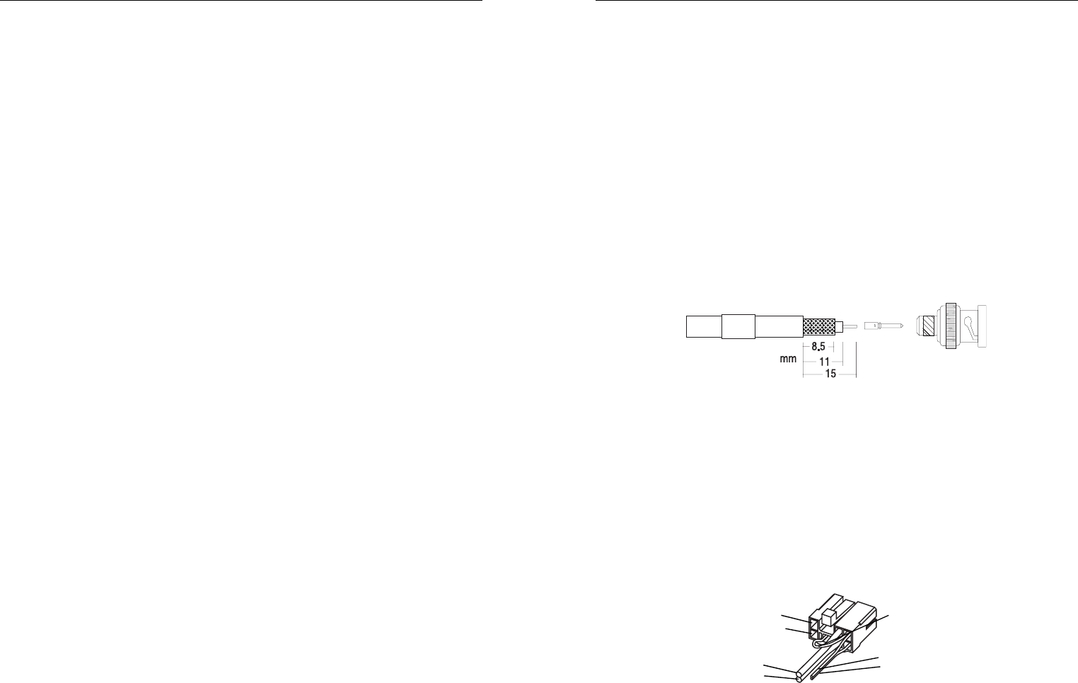
2. Terminate the free end of the cable with the BNC crimp plug supplied, as shown in Figure 4:
Fit the crimp sleeve over the cable sheath.
Trim the outer sheath from the cable to 15mm.
Trim the braid to 8.5mm.
Trim the dielectric to 11mm. (Take extreme care not to ‘nick’ the centre conductor with the
trimming device).
Fit the male pin onto the centre conductor with the shoulder pressed against the
end of the dielectric.
Crimp the male pin onto the centre conductor.
Press the assembly firmly into the rear of the plug. (Check that no braid gets
trapped between the dielectric and the inside of the plug.)
Slide the crimp sleeve over the braid and press against the shoulder of the plug.
Crimp the crimp sleeve onto the braid and plug body.
Figure 4 Antenna Connector Assembly
Wiring
External Speaker
Some T2000II models are fitted with internal speakers. However it is possible to fit an external
speaker if required, by terminating a twin wire in the power connector. To disable the internal
speaker, cut the link on the power connector as shown in Figure 5.
T2000II models with no internal speaker must have an external speaker fitted. The power connector
comes pre-wired with the speaker cable.
Figure 5 Power Connector Wiring
Mount the external speaker in a convenient location close to the operator. Run the free end of the
speaker wire to the speaker, and connect it to the speaker plug.
Ignition
External
Power } +13.8V
Supply } Ground
Ground } External
Live } Speaker
Internal Speaker Link
(cut to disable)

8T2000 Installation Guide
four cradle cover mounting holes as a template to mark the locations for drilling. Ensure that
drilling at the selected points will not damage existing wiring.
2. Indent the drilling positions with a centre punch and drill 4mm holes for self-tapping screws, or
6mm holes for nuts and bolts. Reduce the hole size if using self-tapping screws in metal which is
less than 1mm thick.
3. Drill any additional holes required for cables and fit them with suitable grommets or bushings.
4. Secure the metal cradle cover to the mounting points with the M5 self-tapping screws supplied,
or with M5 nuts and bolts. Ensure that tightening the screws or bolts does not distort the cradle.
To Reassemble the Cradle
1. Reassemble the cradle by clipping one plastic side moulding to each side of the mounted metal
cover (as shown in Figure 3). Take care to locate the ribs on the plastic part in the slots on the
shoulders of the metal cover. They will only fit one way round.
2. Take the remaining metal cover and fit it over the exposed edges of the side mouldings, again
taking care to align the ribs with the slots. Clip it securely home.
Figure 3 Cradle Reassembly
Antenna Installation
RF Exposure Hazard
Mount the antenna in such a position that no part of the human body will normally be within 1m of
it for more than a few minutes while the radio is switched on, unless there is an intervening metal
screen.
Notice to 900MHz Users Only (as per FCC Requirements)
To comply with FCC RF exposure limits, this product must be installed using a 4.5dBi gain antenna.
This antenna must not be mounted at a location such that any person or persons can come closer
than the minimum safe distance to the antenna.
The minimum safe distance is 0.82m (32.5 inches).
T2000 Installation Guide 5
Table of Contents
Software licence agreement ................................................................................................................. 3
Components of the T2000II Radio Kit ............................................................................................... 6
Recommended Installation Tools ....................................................................................................... 6
Installation of Your Radio .................................................................................................................. 6
Occupant’s Safety ......................................................................................................................... 7
To Disassemble the Cradle ........................................................................................................... 7
Mounting ............................................................................................................................................7
To Reassemble the Cradle .................................................................................................................. 8
RF Exposure Hazard .......................................................................................................................... 8
Antenna Installation ...................................................................................................................... 8
Wiring ................................................................................................................................................ 9
External Speaker ........................................................................................................................... 9
Power Cable ................................................................................................................................ 10
External Wire (Horn/Hush/Emergency) ............................................................................................ 10
Remote Control Head Option ........................................................................................................... 10
Microphone Clip .............................................................................................................................. 11
Installation Checks ........................................................................................................................... 11
6T2000 Installation Guide
Components of the T2000II Radio Kit
The T2000II Radio kit includes the following parts:
•T2000II Radio kit
•BNC Antenna Crimp Plug
•Microphone
•Cradle Keys (2)
•Complete Cradle
•Power Cable (5m)
•4 Ohm Speaker (not for internal speaker models)
•Installation Kit:
Two-way hermaphroditic connector (1)
Socket receptacle (2)
10A 12V Blade fuse (2)
Inline crimp fuse holder (2)
Self tapping screw (4)
Shakeproof washer (4)
Microphone clip kit (1)
Control head mounting bracket (T2020II and T2040II only)
Recommended Installation Tools
•Portable Drill
•Centre Punch
•Drill Bits: 4mm for self-tapping screws, 6mm for nuts and bolts
•“Pozidriv” Screwdrivers
•BNC Crimp Tool (e.g. Transradio England Duo crimp 894)
•In-line Power Meter capable of measuring forward and reflected power at the operating fre-
quency of the radio
•Hammer
Installation of Your Radio
To ensure trouble-free, efficient installation, inspect the vehicle and determine how and where the
antenna, radio and accessories are to be mounted.
It is possible to remote-mount the T2020II, T2040II and T2050II models as these have alphanumeric
keypads, with the control head separate from the radio chassis. This enables the radio to be
mounted in a discrete location, e.g. the rear luggage space, with the control head mounted in a con-
venient position for the vehicle’s occupants. See the M2000 service manual, available from your Tait
dealer, for details of this modification.
T2000 Installation Guide 7
Occupant’s Safety
Check that the chosen locations for the radio and accessories do not endanger the vehicle occupants.
Overhead mounting is not recommended, especially without an additional safety strap. Check that
the radio may be conveniently operated when seat belts are worn.
Caution: To prevent interference with vehicle electronic systems (such as ignition and anti-skid
devices), the radio, its antenna and wiring should be mounted away from these units and
their associated cables.
Allow sufficient airflow around the radio to permit adequate cooling. Once you have found a suita-
ble mounting position for the radio, hold it (fitted in the cradle) in the proposed mounting position
and check there is clearance behind it for the heatsink, cables, etc. Check that the position provides a
large enough flat surface that the cradle will not be distorted.
To Disassemble the Cradle
1. Remove the radio from its cradle by sliding the plastic key supplied with the radio fully into the
slot on the left front of the radio unit. The radio will now slide out forwards from the cradle, as
shown below:
Figure 1 Cradle and Key
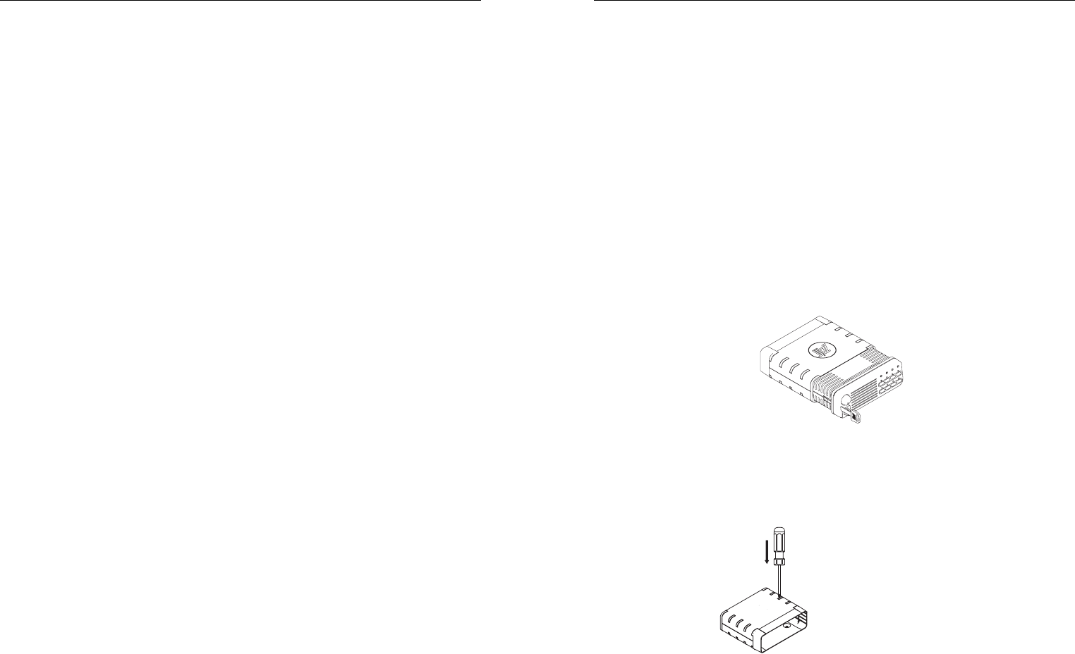
2. Disassemble the cradle by placing it on a firm surface and applying pressure down on one of the
middle ribs of the plastic side moulding with a screwdriver. This will release the ribs along this
edge from the slots in the metal cover with which they mate. A similar approach will release the
other edge of the metal cover which can now be lifted clear (as shown below).
Figure 2 Cradle Assembly
Mounting
1. Hold the drilled half of the metal cradle cover in the position chosen for the radio and use the