Tait TMAB1C Mobile Transceiver User Manual Exhibit D Users Manual per 2 1033 c3
Tait Limited Mobile Transceiver Exhibit D Users Manual per 2 1033 c3
Tait >
Exhibit D Users Manual per 2 1033 c3

March 2004 © Tait Electronics Ltd Tait general software licence agreement
1
Tait general software licence agreement
This legal document is an Agreement
between you (the “Licensee”) and Tait
Electronics Limited (“Tait”). By using any
of the Software or Firmware items prior-
installed in the related Tait product,
included on this CD or downloaded from
the Tait website, (hereinafter referred to
as “the Software or Firmware”) you
agree to be bound by the terms of this
Agreement. If you do not agree to the
terms of this Agreement, do not install
and use any of the Software or
Firmware. If you install and use any of
the Software or Firmware that will be
deemed to be acceptance of the terms of
this licence agreement.
The terms of this agreement shall apply
subject only to any express written terms
of agreement to the contrary between
Tait and the Licensee.
Licence
TAIT GRANTS TO YOU AS LICENSEE THE NON-
EXCLUSIVE RIGHT TO USE THE SOFTWARE OR
FIRMWARE ON A SINGLE MACHINE PROVIDED
YOU MAY ONLY:
1. COPY THE SOFTWARE OR FIRMWARE INTO
ANY MACHINE READABLE OR PRINTED
FORM FOR BACKUP PURPOSES IN SUPPORT
OF YOUR USE OF THE PROGRAM ON THE
SINGLE MACHINE (CERTAIN PROGRAMS,
HOWEVER, MAY INCLUDE MECHANISMS TO
LIMIT OR INHIBIT COPYING, THEY ARE
MARKED “COPY PROTECTED”), PROVIDED
THE COPYRIGHT NOTICE MUST BE REPRO-
DUCED AND INCLUDED ON ANY SUCH COPY
OF THE SOFTWARE OR FIRMWARE; AND / OR
2. MERGE IT INTO ANOTHER PROGRAM FOR
YOUR USE ON THE SINGLE MACHINE (ANY
PORTION OF ANY SOFTWARE OR FIRMWARE
MERGED INTO ANOTHER PROGRAM WILL
CONTINUE TO BE SUBJECT TO THE TERMS
AND CONDITIONS OF THIS AGREEMENT).
THE LICENSEE MAY NOT DUPLICATE, MODIFY,
REVERSE COMPILE OR REVERSE ASSEMBLE ANY
SOFTWARE OR FIRMWARE IN WHOLE OR PART.
Title to Software
THIS AGREEMENT DOES NOT CONSTITUTE A
CONTRACT OF SALE IN RELATION TO THE SOFT-
WARE OR FIRMWARE SUPPLIED TO THE LICEN-
SEE. NOT WITHSTANDING THE LICENSEE MAY
OWN THE MAGNETIC OR OTHER PHYSICAL
MEDIA ON WHICH THE SOFTWARE OR
FIRMWARE WAS ORIGINALLY SUPPLIED, OR HAS
SUBSEQUENTLY BEEN RECORDED OR FIXED, IT IS
A FUNDAMENTAL TERM OF THIS AGREEMENT
THAT AT ALL TIMES TITLE AND OWNERSHIP OF
THE SOFTWARE OR FIRMWARE, WHETHER ON
THE ORIGINAL MEDIA OR OTHERWISE, SHALL
REMAIN VESTED IN TAIT OR THIRD PARTIES
WHO HAVE GRANTED LICENCES TO TAIT.
Term and Termination
THIS LICENCE SHALL BE EFFECTIVE UNTIL TERMI-
NATED IN ACCORDANCE WITH THE PROVISIONS
OF THIS AGREEMENT. THE LICENSEE MAY
TERMINATE THIS LICENCE AT ANY TIME BY
DESTROYING ALL COPIES OF THE SOFTWARE OR
FIRMWARE AND ASSOCIATED WRITTEN MATERI-
ALS. THIS LICENCE WILL BE TERMINATED AUTO-
MATICALLY AND WITHOUT NOTICE FROM TAIT
IN THE EVENT THAT THE LICENSEE FAILS TO
COMPLY WITH ANY TERM OR CONDITION OF
THIS AGREEMENT. THE LICENSEE AGREES TO
DESTROY ALL COPIES OF THE SOFTWARE OR
FIRMWARE AND ASSOCIATED WRITTEN MATERI-
ALS IN THE EVENT OF SUCH TERMINATION.
2Tait general software licence agreement
Limited Warranty
THE
SOFTWARE
OR
FIRMWARE
IS
SUPPLIED
BY
TAIT
AND
ACCEPTED
BY
THE
LICENSEE
“
AS
IS
”
WITHOUT
WARRANTY
OF
ANY
KIND
EITHER
EXPRESSED
OR
IMPLIED
,
INCLUDING
BUT
NOT
BEING
LIMITED
TO
ANY
IMPLIED
WARRANTIES
AS
TO
MERCHANTABIL
-
ITY
OR
FITNESS
FOR
ANY
PARTICULAR
PURPOSE
.
THE
LICENSEE
ACKNOWLEDGES
THAT
THE
SOFT
-
WARE
OR
FIRMWARE
IS
USED
BY
IT
IN
BUSINESS
AND
ACCORDINGLY
TO
THE
MAXIMUM
EXTENT
PERMITTED
BY
LAW
NO
TERMS
OR
WARRANTIES
WHICH
ARE
IMPLIED
BY
LEGISLATION
SHALL
APPLY
TO
THIS
AGREEMENT
.
TAIT
DOES
NOT
WARRANT
THAT
THE
FUNCTIONS
CONTAINED
IN
THE
SOFT
-
WARE
OR
FIRMWARE
WILL
MEET
THE
LICENSEE
’
S
REQUIREMENTS
OR
THAT
THE
OPERATION
OF
THE
SOFTWARE
OR
FIRMWARE
WILL
BE
UNINTERRUPTED
OR
ERROR
FREE
.
Exclusion of Liability
TAIT’S ENTIRE LIABILITY AND THE LICENSEE’S
EXCLUSIVE REMEDY SHALL BE THE FOLLOWING:
1. IN NO CIRCUMSTANCES SHALL TAIT BE UNDER
ANY LIABILITY TO THE LICENSEE, OR ANY
OTHER PERSON WHATSOEVER, FOR ANY
DIRECT OR CONSEQUENTIAL DAMAGE ARIS-
ING OUT OF OR IN CONNECTION WITH ANY
USE OR INABILITY OF USING THE SOFTWARE OR
FIRMWARE.
2. TAIT WARRANTS THE OPERATION OF THE SOFT-
WARE OR FIRMWARE ONLY WITH THE OPERAT-
ING SYSTEM FOR WHICH IT WAS DESIGNED.
USE OF THE SOFTWARE OR FIRMWARE WITH
AN OPERATING SYSTEM OTHER THAN THAT
FOR WHICH IT WAS DESIGNED MAY NOT BE
SUPPORTED BY TAIT, UNLESS OTHERWISE
EXPRESSLY AGREED BY TAIT.
General
THE LICENSEE CONFIRMS THAT IT SHALL
COMPLY WITH THE PROVISIONS OF LAW IN
RELATION TO THE SOFTWARE OR FIRMWARE.
Law and Jurisdiction
THIS AGREEMENT SHALL BE SUBJECT TO AND
CONSTRUED IN ACCORDANCE WITH NEW
ZEALAND LAW AND DISPUTES BETWEEN THE
PARTIES CONCERNING THE PROVISIONS HEREOF
SHALL BE DETERMINED BY THE NEW ZEALAND
COURTS OF LAW. PROVIDED HOWEVER TAIT
MAY AT ITS ELECTION BRING PROCEEDINGS FOR
BREACH OF THE TERMS HEREOF OR FOR THE
ENFORCEMENT OF ANY JUDGEMENT IN RELA-
TION TO A BREACH OF THE TERMS HEREOF IN
ANY JURISDICTION TAIT CONSIDERS FIT FOR THE
PURPOSE OF ENSURING COMPLIANCE WITH THE
TERMS HEREOF OR OBTAINING RELIEF FOR
BREACH OF THE TERMS HEREOF.
No Dealings
THE
LICENSEE
MAY
NOT
SUBLICENSE
,
ASSIGN
OR
TRANSFER
THE
LICENCE
OR
THE
PROGRAM
EXCEPT
AS
EXPRESSLY
PROVIDED
IN
THIS
AGREE
-
MENT
.
ANY
ATTEMPT
OTHERWISE
TO
SUBLICENSE
,
ASSIGN
OR
TRANSFER
ANY
OF
THE
RIGHTS
,
DUTIES
OR
OBLIGATIONS
HEREUNDER
IS
VOID
.
No Other Terms
THE LICENSEE ACKNOWLEDGES THAT IT HAS
READ THIS AGREEMENT, UNDERSTANDS IT AND
AGREES TO BE BOUND BY ITS TERMS AND
CONDITIONS. THE LICENSEE FURTHER AGREES
THAT SUBJECT ONLY TO ANY EXPRESS WRITTEN
TERMS OF AGREEMENT TO THE CONTRARY
BETWEEN TAIT AND THE LICENSEE THIS IS THE
COMPLETE AND EXCLUSIVE STATEMENT OF THE
AGREEMENT BETWEEN IT AND TAIT IN RELATION
TO THE SOFTWARE OR FIRMWARE WHICH SUPER-
SEDES ANY PROPOSAL OR PRIOR AGREEMENT,
ORAL OR WRITTEN AND ANY OTHER COMMUNI-
CATIONS BETWEEN THE LICENSEE AND TAIT
RELATING TO THE SOFTWARE OR FIRMWARE.

About this guide 3
About this guide
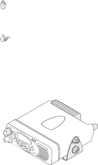
This user’s guide provides information about the TM8250
and TM8255 mobile radios and is divided into two parts.
■Part A explains how the TM8255 radio operates. The
TM8250 radio has a control head without user controls, so
no TM8250 operating information is needed.
■Part B outlines the installation procedure for both TM8250
and TM8255 radios and describes the pin allocations of the
two programming connectors
on the
TM8250 control head.
Important safety information
This user’s guide also contains important safety information
about using and installing TM8250 and TM8255 radios.
Refer to page 11 for user safety and compliance instructions
and page 30 for installation safety instructions.
Alert notices
Within this guide, four types of alerts are given to the reader:
warning, caution, important and note. The following para-
graphs illustrate each type of alert and its associated symbol.
Warning: There is a potential risk of death or serious injury.
Caution: There is the risk of minor or moderate injury
to people.
Important: There is a risk of equipment damage or malfunction.
Note: This highlights information that is required to ensure
that procedures are performed correctly.
Updating this guide
In the interests of improving the performance, reliability or
servicing of the equipment, Tait Electronics Ltd reserves the
right to update both the equipment or this user’s guide,
without prior notice.
4About this guide
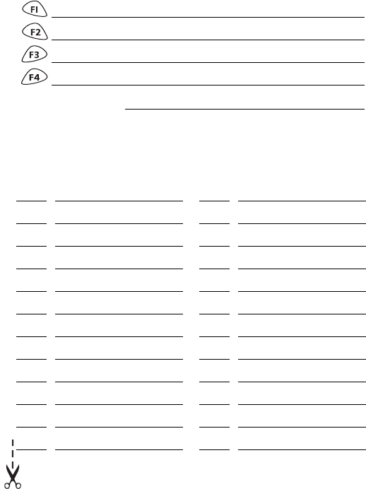
Your radio’s settings
Use the following table to list your radio’s programmed settings.
Frequently used channels
Function key settings
quick access menu:
ID Description ID Description
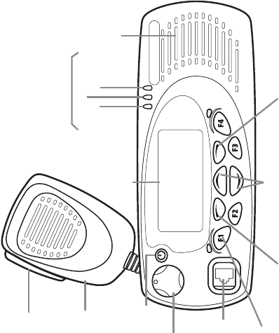
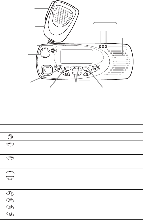
scroll keys
on/off key
volume
control
microphone
socket
PTT key
(press-to-talk)
red
LCD
(liquid crystal
display) speaker
green
amber
microphone
radio status LEDs
function keys
1 to 4 left selection key right selection key
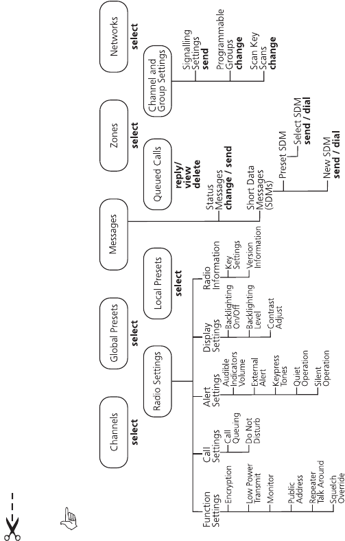
Navigating your radio’s menus
Main menu: conventional mode
Note: Only menus associated with features programmed on your radio will be available.
.
Radio operation 9
Part 1: Radio operation
Tait general software licence agreement ................................... 1
About this guide .......................................................................... 3
Important safety information ....................................................................... 3
Alert notices ............................................................................................... 3
Updating this guide .................................................................................... 3
Your radio’s settings .................................................................... 5
Navigating your radio’s menus ................................................... 7
Safety and compliance warnings .............................................. 11
Radio frequency exposure information ...................................................... 11
Using this radio .................................................................................. 11
Controlling your exposure to RF energy ..................................................... 11
Compliance with RF energy exposure standards ........................................ 12
Warning: Safe radio operation .................................................................. 13
Caution: EN 60950 requirements .............................................................. 13
Caution: High temperatures ...................................................................... 13
Important: Radio protection ...................................................................... 13
Getting started ........................................................................... 14
Radio controls .......................................................................................... 14
Radio indicators ........................................................................................ 16
Radio display ...................................................................................... 16
Radio display icons ............................................................................. 17
LED indicators .................................................................................... 18
Audible tones ..................................................................................... 18
Basic operation ........................................................................... 19
Turning the radio on and off ..................................................................... 19
Entering your PIN ..................................................................................... 19
Adjusting the speaker volume ................................................................... 19
Using the radio menu ............................................................................... 19
Quick access menu ............................................................................. 20
Selecting a channel or group ..................................................................... 20
Making a call ........................................................................................... 20
Making a call on a conventional network ............................................ 20
Making a call on an MPT trunked network .......................................... 21
Transmit timer .................................................................................... 21
Receiving a call ......................................................................................... 21
10 Radio operation
Changing networks .................................................................................. 22
What you hear on a channel ..................................................................... 22
Signalling mute .................................................................................. 23
Squelch .............................................................................................. 23
Checking that a channel is clear ................................................................ 23
Activating monitor using the monitor function key ............................... 23
Activating monitor using the menu ..................................................... 24
Troubleshooting .........................................................................25
When your radio won’t turn on ................................................................. 25
Removing the radio from the vehicle ......................................................... 25
Audible tones ........................................................................................... 26
Notes ............................................................................................ 28
Safety and compliance warnings 11
Safety and compliance warnings
Radio frequency exposure information
For your own safety and to ensure you comply with the
Federal Communication Commission’s (FCC) radio
frequency (RF) exposure guidelines, please read the following
information before using this radio.
Using this radio
You should use this radio only for work-related purposes (it is
not authorized for any other use) and if you are fully aware
of, and can exercise control over, your exposure to RF energy.
To prevent exceeding FCC RF exposure limits, you must
control the amount and duration of RF that you and other
people are exposed to.
It is also important that you:
■Do not remove the RF Exposure label from the radio.
■Ensure this RF exposure information accompanies the
radio when it is transferred to other users.
■Do not use the radio if you do not adhere to the guide-
lines on controlling your exposure to RF.
Controlling your exposure to RF energy
This radio emits radio frequency (RF) energy or radio waves
primarily when calls are received and made. RF is a form of
electromagnetic energy (as is sunlight), and there are recom-
mended levels of maximum RF exposure.
To control your exposure to RF and comply with the maxi-
mum exposure limits for occupational/controlled environ-
ments, follow these guidelines:
■Do not talk (transmit) on the radio more than the rated
transmit duty cycle. This is important because the radio
radiates more energy when it is transmitting than when
it is receiving.
12 Safety and compliance warnings
■While you are transmitting (talking or sending data) on
the radio, you must ensure that there is always a distance
of 0.9m (35 inches) between people and the antenna.
This is the minimum safe distance.
■Use the radio only with Tait-approved antennas and
attachments, and make only authorized modifications to
the antenna otherwise you could damage the radio and
violate FCC regulations.
For more information on what RF energy is and how to
control your exposure to it, visit the FCC website at http://
www.fcc.gov/oet/rfsafety/rf-faqs.html.
Compliance with RF energy exposure standards
This two-way radio complies with these RF energy exposure
standards and guidelines:
■United States Federal Communications Commission,
Code of Federal Regulations; 47 CFR part 2 subpart J
■American National Standards Institute (ANSI) / Institute
of Electrical and Electronic Engineers (IEEE) C95. 1-1992
■Institute of Electrical and Electronic Engineers (IEEE)
C95.1-1999 Edition.
This radio complies with the IEEE (FCC) and ICNIRP exposure
limits for occupational/controlled RF exposure environments
at operating duty factors of up to 50% talk to 50% listen.
Safety and compliance warnings 13
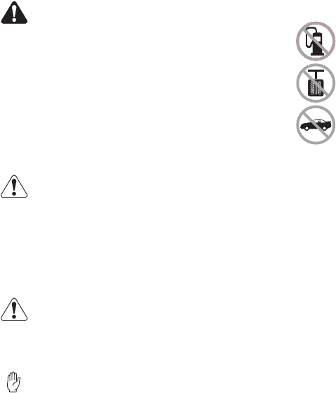
Warning: Safe radio operation
■Switch the radio off at petrol filling stations
or near flammable liquids or gases.
■Switch the radio off in the vicinity of explo-
sive devices and blasting zones.
■Using a handheld microphone or a radio while
driving a vehicle may violate the laws and legis-
lation that apply in your country or state. Please
check the vehicle regulations in your area.
Caution: EN 60950 requirements
This radio complies with the European Union standard
EN 60950 when operated up to the rated 33% duty cycle of
two minutes transmit and four minutes receive, and with
ambient temperatures of 30°C or lower.
Operation outside these limits may cause the external temper-
ature of the radio to rise higher than this standard permits.
Caution: High temperatures
The bottom surface of the radio and the heatsink fins can
become hot during prolonged operation. Do not touch these
parts of the radio.
Important: Radio protection
Always remove the fuses from the radio power cable before
charging the vehicle battery, connecting a second battery or
using power from another vehicle (e.g. when “jump-
starting” the vehicle).
14 Getting started
Getting started
This section provides a brief description of your radio’s
basic operation. If you need further information, contact
your radio provider.
Radio controls
The radio controls are the PTT key, volume control, on/off key,
scroll keys, selection keys and function keys. Some keys may
have functions assigned to both short and long key presses:
■a short key press is defined as less than one second, and
■a long key press is more than one second.
The radio controls and their functions are summarized in the
diagram and table on the following page.
Getting started 15
scroll keys
on/off key
volume
control
microphone
socket
PTT key
(press-to-talk)
red
LCD
(liquid crystal
display) speaker
green
amber
microphone
radio status LEDs
function keys
1 to 4 left selection key right selection key
Symbol Name Function
PTT press and hold to transmit and release
to listen
MPT mode: initiates a call from the idle state
volume control rotate to change the speaker volume
power key turn the radio on or off with a long press
left selection key action determined by the text above the left
selection key
right selection key action determined by the text above the right
selection key
scroll keys scroll up and down through a list of menu
options or scroll left and right in messages, or
access the lists of channels or preset calls
function keys
1, 2, 3 and 4
function keys with programmed options
16 Getting started
Radio indicators
The radio display, LED indicators and the radio’s audible
tones all combine to give you information about the state
of your radio.
The most common operation of the radio display and indica-
tors is described in the following sections.
Note: The way these indicators behave may be
affected by the way your radio is programmed.
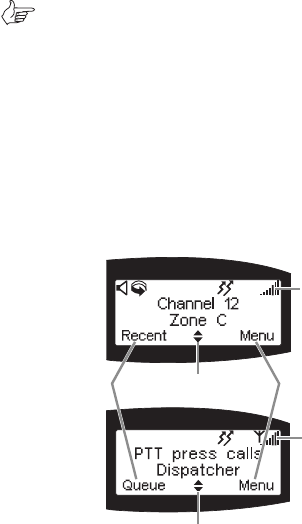
Radio display
The messages and icons you see in your radio display
depends upon the mode in which your radio is operating.
Also, your radio may be programmed to display programmed
information on start-up, such as your network identity.
The following diagrams show two typical displays, one of a
radio operating in conventional mode and the other in
MPT trunked mode.
conventional
mode display
MPT trunked
mode display
scrolling icon
scrolling icon
left selection
key text
right selection
key text
radio display
icons
radio display
icons
Getting started 17
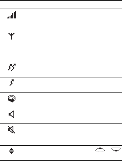
Radio display icons
Icon Meaning
RSSI (received signal strength indicator): the
more bars on the indicator, the stronger the
signal being received by your radio.
MPT network available: your radio has access to
an MPT network
flashing: your radio is attempting to access
an MPT network
transmit: your radio is transmitting
low-power transmit: your radio is transmitting
on low-power
scanning: your radio is monitoring a group of
channels for activity
monitor or squelch override: monitor or squelch
override is active
quiet mode: you are in quiet mode and your
radio keypress tones and confidence tones have
been turned off
scrolling: you can use the scroll keys or
to move through a list
18 Getting started
LED indicators
Audible tones
Note: If quiet or silent mode has been turned on, you
will not hear any audible tones.
Refer to page 26 for a description of other tones you may hear.
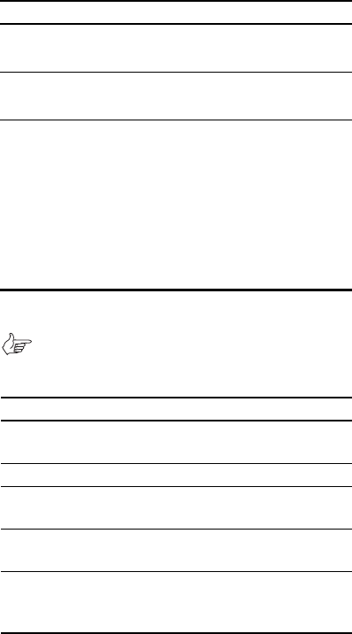
LED Meaning
red
(transmit)
glowing: your radio is transmitting
flashing: your transmit timer is about to expire
green
(receive)
glowing: you are receiving
flashing: you have received a call
amber
(scanning or
network)
glowing: your radio is scanning a group of chan-
nels for activity (conventional mode) or network
service is available (MPT trunked mode)
flashing: your radio has detected activity on
a channel, and has halted on this channel
(conventional mode)
flashing fast: in trunked mode, there is no
network service available
Tone type
Meaning
two short beeps
radio turned on: the radio is powered on
and ready to use
one short beep
radio turned off: the radio is powered off
one short beep
valid keypress: the action you have
attempted is permitted
one long, low-
pitched beep
invalid keypress: the action you have
attempted is not permitted
one long, low-
pitched beep
transmission inhibited: you have attempted
to transmit but for some reason transmis-
sion is not permitted at this time
Basic operation 19
Basic operation
This section describes the basic operation of your radio, includ-
ing turning the radio on and off and adjusting the volume.
Turning the radio on and off
A long press of the on/off key turns the radio either on or
off. When the radio is first turned on, the red, green and
amber LEDs flash briefly and the radio gives two short beeps.
Entering your PIN
You may need to enter a PIN (personal identification number)
before you can use your radio. If the message radio locked
enter pin is displayed, enter your assigned PIN.
Once you have entered you PIN correctly, the pin accepted
message appears and normal operation is now possible.
If you do not know your PIN or you receive the incorrect pin
message after entering your PIN, consult your radio provider.
Adjusting the speaker volume
Rotate the volume control clockwise to increase the
speaker volume and counterclockwise to decrease the
volume. The volume control also changes the volume level
of the radio’s audible indicators.
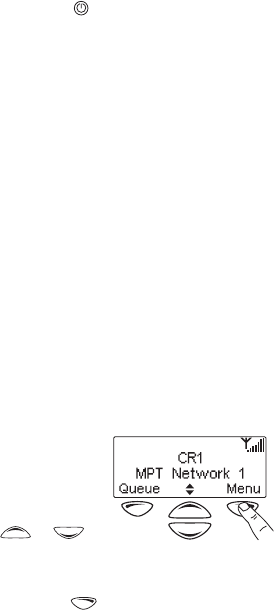
Using the radio menu
Whenever Menu appears above
the right selection key, press the
right selection key to enter the
main menu.
Use the scroll keys or to
move through the list of menus.
When the menu you want is highlighted, press Select
using the right selection key and the menu you have
chosen is displayed.

20 Basic operation
Quick access menu
A menu that is used frequently may be programmed as your
quick access menu. To go to your quick access menu, press a
scroll key or , and the menu is displayed.
For example, if your channels menu is your quick access
menu, press a scroll key or to go directly to the
channels menu.
Selecting a channel or group
To select a channel or group you can either:
■use the scroll keys or to scroll through the
channel list until the channel or group you want is
displayed, or
■
use the menu (see “Using the radio menu” on page 19).
Making a call
The network that your radio is operating on determines the
way you make a call. The two network options that affect the
calling procedure are:
■conventional, and
■MPT trunked.
Making a call on a conventional network
1. Select the required channel, group or zone.
2. Check the green LED.
If the green LED is glowing, the channel is busy and you
cannot transmit.
3. Once the channel is clear (the green LED is off), lift the
microphone off the microphone clip.
4. Hold the microphone about 5cm (2 inches) from your
mouth and press the PTT key to transmit.

Basic operation 21
5. Speak clearly into the microphone and release the PTT
key when you have finished talking.
Note: You cannot change channels while
transmitting.
Making a call on an MPT trunked network
1. Select the required channel, and press the PTT key.
2. Once the person you have called replies, lift the micro-
phone off the microphone clip.
3. Hold the microphone about 5cm (2 inches) from your
mouth and press the PTT key to transmit.
4. Speak clearly into the microphone and release the PTT
key when you have finished talking.
Transmit timer
Your radio may have a transmit timer that limits the amount
of time you can transmit continuously. When the transmit
timer is about to expire, the red LED flashes and the radio
gives three beeps. You must release the PTT before you can
transmit again.
Note: Your radio may be unable to transmit for a short
time after the transmit timer has expired.
Receiving a call
When there is valid activity on your radio’s currently
selected channel or group, the radio then unmutes and you
can hear the call.
If the incoming call contains special signalling that matches
the signalling programmed for your radio, the green LED
flashes and your radio may give a ringing tone.
22 Basic operation
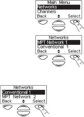
Changing networks
1. Press Menu and scroll through
the list of menu items until
Networks is displayed.
2. Press Select to enter the
Network Menu and the current
network is highlighted.
3. Scroll down the list until the required network option is
displayed, and press
Select
.
4. Press
Yes
when you are prompted to confirm your selection.
What you hear on a channel
Your radio may be programmed so that you hear all conversa-
tions on a channel, or your user group may be segregated from
other user groups by using special signalling. The special
signalling is used to control the muting and unmuting of your
radio, so that your radio is muted when other user groups are
talking and unmuted for members of your user group.
The two muting controls that operate in your radio are:
■signalling mute, and
■squelch.

Basic operation 23
Signalling mute
The radio’s signalling mute only allows the radio to unmute if
the incoming call carries the tones specific to your user
group. Your user group may use tones that are either audible,
subaudible or both.
Squelch
The radio’s squelch allows the radio to unmute only when the
strength of the incoming signal is above a predetermined
threshold. This means that only signals of reasonable intelli-
gibility are made audible.
Checking that a channel is clear
Use the monitor function to check that the channel is clear
before you make a call. While monitor is on, the green LED
flashes continually and the monitor icon is displayed.
To activate monitor, you can either:
■use a function key that may have been programmed for
monitor, or
■use the menu.
Activating monitor using the monitor
function key
1. Press the monitor function key and monitor overrides
the signalling mute, allowing you to hear any traffic on
the channel.
Note: Your radio may be programmed to activate
monitor whenever the microphone is off the
microphone clip.
2. Press the monitor function key again to turn monitor off.
24 Basic operation
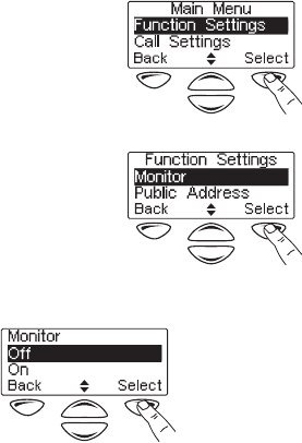
Activating monitor using the menu
1. Press Menu, and scroll through
the list of menu items until
Function Settings
is displayed.
2. Press Select to enter the func-
tion settings menu, then scroll
down the list of menu items
until Monitor is displayed.
3. Press Select to select monitor, then Select to select On.
Troubleshooting 25
Troubleshooting
When your radio won’t turn on
If the red, green and amber LEDs on the control head do not
light up when the radio is turned on, it is likely that no power
is reaching the radio. Check the following:
■Is the power connector firmly plugged into the rear of
the radio?
■Are the in-line fuses in good condition?
■Is the power cable securely connected to the vehicle bat-
tery or power supply?
If all appears to be in order, then contact your radio provider
for further assistance.
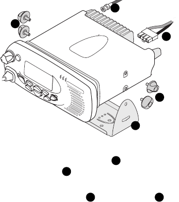
Removing the radio from the vehicle
1. Switch off the radio.
2. Unscrew the four thumb screws that secure the radio
to the U-bracket .
3. Lift the radio clear of the U-bracket.
4. Disconnect the antenna and power cable from
the rear of the radio.
b
a
a
c
d
a
b
cd

26 Troubleshooting
Audible tones
The following table gives a list of the radio’s audible tones,
additional to those explained on page 18.
Action and tone Meaning
one short beep after the
power-up beeps
radio locked: you need to enter your PIN
(personal identity number) before you
can use the radio
one long, low-pitched
beep
radio PIN entry unsuccessful: you need
to re-enter your PIN
two short beeps
radio PIN entry successful: the radio is
ready to use
one short beep
function activated: a function key has
been pressed and that function has
been initiated
one short, low-pitched
beep
function de-activated: a function key
has been pressed and the correspond-
ing function has been turned off
one long, low-pitched
beep
transmission inhibited: you have
attempted to transmit but for some reason
transmission is not permitted at this time
one short, high-pitched
beep
radio is stunned: the radio has been
made inoperable by your service provider
two short beeps
radio is revived: the radio has made
operable by your service provider
three beeps transmit timeout imminent: in 10 seconds
your transmit timer will expire and your
current transmission will be terminated
two low-pitched beeps
radio's temperature is high: the
radio's temperature is in the high-
temperature range, but the radio will
continue to operate

Troubleshooting 27
two high-pitched beeps radio's temperature is very high: the
radio's temperature is in the very high
temperature range and all transmissions
will now be at low power; if the radio's
temperature rises outside this range,
transmissions will be inhibited
continuous low-pitched
tone
radio system error: a system error has
occurred and the radio may be inoper-
able. (the LCD usually displays either
E1
or
E2
)
two long low-high
pitched tone pairs
synthesizer is out-of-lock: the radio's
synthesizer is out-of-lock on the current
channel and you cannot operate on that
channel (LCD will usually be flashing
OL
)
Action and tone Meaning
28 Notes
Notes
Radio installation procedures 29
Part 2: Radio installation procedures
Installation warnings ................................................................. 30
Warning: Safe radio mounting .................................................................. 30
Warning: Interference with vehicular electronics ........................................ 30
Warning: Liquefied petroleum gas powered vehicles .................................. 30
Important: Non-standard radio installations .............................................. 31
Important: Negative ground supply ........................................................... 31
Installation planning .................................................................. 32
MPT 1362 code of practice ....................................................................... 32
Checking equipment ................................................................................. 32
Installation tools ....................................................................................... 32
Microphone clip installation tools (TM8255 only) ................................ 33
Mounting position .................................................................................... 33
Radio Installation ....................................................................... 34
Mounting the U-bracket ........................................................................... 34
Control head handling precautions ........................................................... 34
Installing the control head on the radio body ............................................ 34
Removing the control head ....................................................................... 35
Installing the microphone ......................................................................... 36
Installing the antenna ............................................................................... 36
Warning: RF exposure hazard ............................................................. 36
Antenna termination ........................................................................... 37
Power cable ............................................................................................. 37
Installing the power cable ................................................................... 37
Installing the radio in the U-bracket .......................................................... 38
Microphone clip (TM8255 radios only) ...................................................... 39
TM8250 connectors .................................................................................. 39
Installation checks .................................................................................... 40
Other installation options ......................................................... 40

30 Installation warnings
Installation warnings
Warning: Safe radio mounting
■Mount the radio securely so that it will not break loose in
the event of a collision. An unsecured radio is dangerous
to the vehicle occupants.
■Mount the radio where it will not interfere with the
deployment of passenger air bags.
■Do not mount the radio vertically, with the control head
facing down. This will violate compliance with the Euro-
pean Union standard EN 60950, Safety of Information
Technology Equipment.
Warning: Interference with vehicular electronics
Some vehicular electronic devices may be prone to malfunc-
tion, due to the lack of protection from RF energy present
when your radio is transmitting.
Examples of vehicular electronic devices that may be affected
by RF energy are:
■electronic fuel injection systems
■electronic anti-skid braking systems
■electronic cruise control systems.
If the vehicle contains such equipment, consult the vehicle
manufacturer or dealer in order to determine whether
these electronic circuits will perform normally when the
radio is transmitting.
Warning: Liquefied petroleum gas powered vehicles
Radio installation in vehicles powered by LP (liquefied petro-
leum) gas with the LP gas container in a sealed-off space
within the interior of the vehicle must conform to the
National Fire Protection Association Standard NFPA 58. This
standard states that the radio equipment installation must
meet the following requirements.
Installation warnings 31
■The space containing the radio equipment shall be iso-
lated by a seal from the space containing the LP gas con-
tainer and its fitting.
■Outside filling connections shall be used for the LP gas
container and its fittings.
■The LP gas container space shall be vented to the outside
of the vehicle.
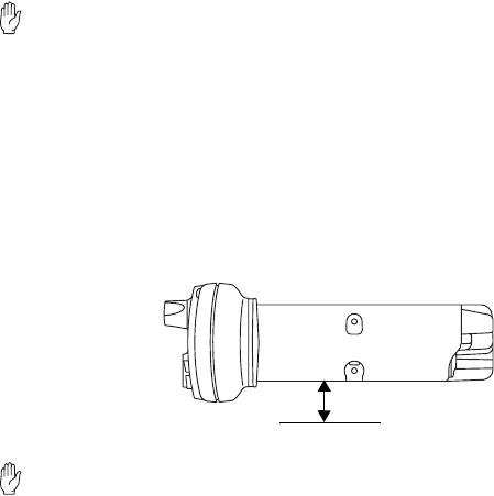
Important: Non-standard radio installations
The installation U-bracket described in this guide has been
designed so that there is enough airflow around the radio
to provide cooling.
If a non-standard installation method is used, care must be
taken that sufficient heat can be dissipated from the radio
heatsink fins and the bottom surface of the radio chassis.
For this to be achieved, there must be a gap of more than
10mm (0.4 inch) between the bottom surface of the radio
chassis and the mounting surface. This is illustrated in the
following diagram.
Important: Negative ground supply
TM8200 radios are designed to operate only in a negative
ground system.
10mm
mounting surface
32 Installation planning
Installation planning
The procedures outlined in this and the following sections
are for installing a TM8250 or TM8255 radio in a vehicle,
using a standard U-bracket.
MPT 1362 code of practice
TM8200 radios should be installed in accordance with the
MPT 1362 Code of Practice. This code of practice covers the
installation of mobile radio equipment in land based vehicles
and has been developed by the United Kingdom Radiocom-
munications Agency.
The full text of the MPT 1362 Code of Practice can be found
at the Radiocommunications Agency website,
www.radio.gov.uk.
Checking equipment
Unpack the radio and check that you have the following items:
■radio control head with connecting loom
■radio body
■microphone with microphone clip and screws
(TM8255 only)
■installation kit, consisting of:
— U-bracket with screws
— power cable with DC connector
— 10A fuses
— fuse holders
— BNC antenna plug.
Installation tools
The following installation tools may be required:
■portable drill
■8mm (0.3 inch) socket
■BNC crimp tool
Installation planning 33
■in-line RF power meter capable of measuring forward and
reflected power at the operating frequency of the radio.
Microphone clip installation tools
(TM8255 only)
The following installation tools may be required for installing
the TM8255 microphone:
■centre punch
■drill bit
■Pozidriv screwdriver
■hammer.
Mounting position
Inspect the vehicle and determine the safest and most
convenient location for mounting the radio.
The installation must meet the following requirements:
■sufficient clearance behind the radio for the heatsink
and cables
■a large enough flat surface so that the mounting bracket
will not be distorted
■no danger of the radio interfering with air
bag deployment.
34 Radio Installation
Radio Installation
Mounting the U-bracket
Screw the U-bracket in the chosen mounting position using
the self-tapping screws provided. At least four screws must
be installed. If the U-bracket is being mounted over a
curved surface, bend the U-bracket tabs slightly.
Important: Check that the U-bracket is not distorted
when the screws are tightened.
Control head handling precautions
Important: The control head contains devices which can
be damaged by static discharges. Always install or
remove the control head in a static-safe environment.
Information on antistatic precautions can be found at the
Electrostatic Discharge Association (ESD) website,
www.esda.org.
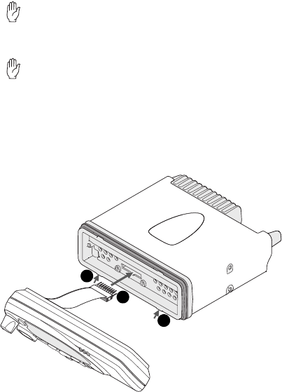
Installing the control head on the radio body
The orientation of the U-bracket mounting determines
which way up the control head is mounted on the radio
2
1
2
Radio Installation 35
body. The numbers in the diagram on the previous page
refer to the numbered steps below.
1. Plug the control head loom onto the control
head connector.
2. Insert the bottom edge of the control head onto the
two clips in the front of the radio chassis, then snap
into place.
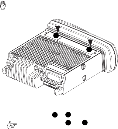
Removing the control head
Important: During this procedure, take care that the
chassis seal is not damaged. Damage to this seal
reduces environmental protection.
1. On the underside of the radio, insert a flat-bladed screw-
driver between the control head and the radio chassis
seal, in either position or .
Note: Insertion points and are indicated
on the radio chassis by a dot-dash-dot
pattern (•–•).
2. Use the screwdriver to lift the control head off the chassis
clip, then repeat in the other position.
The control head can now be removed from the radio body.
1
2
12
12
36 Radio Installation
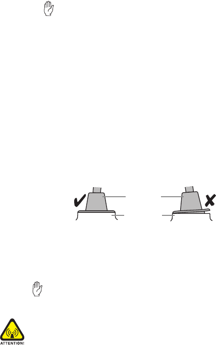
Installing the microphone
Important: The microphone grommet must be installed
whenever the microphone is plugged into the micro-
phone socket. When installed, the grommet has two functions:
■to prevent damage to the microphone socket when there
is movement of the microphone cord, and
■to ensure that the control head is sealed against water,
dust and other environmental hazards.
1. Plug the microphone into the microphone socket on the
control head.
2. Slide the microphone grommet along the microphone
cord and push two adjacent corners of the grommet into
the microphone socket cavity.
3. Squeeze the grommet and push the remaining corners
into position.
4. Check that the grommet is seated correctly in the cavity.
Installing the antenna
Install the external antenna according to the supplier’s
instructions. Good quality 50 ohm coaxial cable must be
used, such as RG58 or UR76.
Important: The cable should be routed in a manner that
minimizes coupling into the electronic control systems
of the vehicle.
Warning: RF exposure hazard
To comply with FCC RF exposure limits, this product must be
installed using an externally mounted antenna with either a
2.15dBi or 5.15dBi gain.
microphone
grommet
control head

Radio Installation 37
This antenna must not be mounted at a location such that
any person or persons can come closer than 0.9m
(35 inches) to the antenna.
Antenna termination
1. Run the free end of the coaxial cable to the radio’s
mounting position and cut it to length, allowing 20 -
30cm (8 - 12 inches) excess.
2. Terminate the free end of the cable with the BNC
plug supplied.
Power cable
Important: This radio is designed to operate from a
nominal 12V negative ground supply and may draw up
to 8A of current. The radio will tolerate a supply voltage
range of 10.8V to 16.0V at the radio.
In vehicles with a supply voltage greater than 16.0V, such as
many trucks, it is essential to provide a suitably rated DC to DC
converter. This will isolate the radio from excessive battery volt-
age and provide the correct DC operating conditions.
Installing the power cable
Important: Disconnecting the vehicle’s battery may
cause problems with some electronic equipment, such
as vehicle alarms, engine management systems and in-car
entertainment systems. Check that the vehicle owner has the
necessary information to make all electronic equipment func-
tion correctly after battery reconnection.
1. Disconnect the vehicle’s battery, unless specifically
prohibited from doing so by the customer, vehicle manu-
facturer, agent or supplier.
If the battery is not disconnected, exercise extreme
caution throughout the installation and install the fuses
only when the installation is ready to be checked (see
“Installation checks” on page 40).
38 Radio Installation
2. Determine where the power cable will be routed.
Important: The power cable should be protected
from engine heat, sharp edges and from being
pinched or crushed.
3. Cut the negative and the positive wires where the in-line fuse
holders will be placed (as close to the battery as possible).
Note: Do not install the fuses until the installation
is ready to be checked.
4. Insert each end of the negative wire into one of the in-
line fuse holders and crimp them to force the metal
contacts onto the wires.
5. Connect the negative wire to the battery ground.
6. Repeat step 4 for the positive wire and connect it to the
positive terminal of the battery.
Installing the radio in the U-bracket
1. Connect the antenna and power cables to the rear of
the radio.
2. Position the radio in the U-bracket so that the holes in the
U-bracket line up with the holes in the radio chassis.
3. Screw the radio into position using the four thumb screws
but without fully tightening the screws.
Radio Installation 39
4. Position the radio in the U-bracket for best viewing angle,
then tighten the thumb screws.
Microphone clip (TM8255 radios only)
Install the microphone clip in the most convenient location
for the radio user. It must be within easy reach of the user,
but in such a position that the microphone PTT key cannot be
inadvertently activated or jammed on.
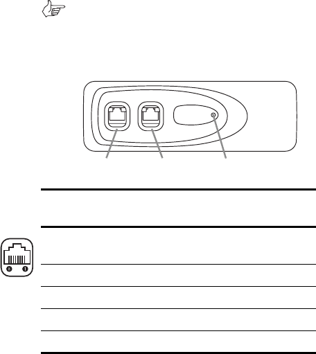
TM8250 connectors
The TM8250 control head has two RJ45 sockets for program-
ming, and a power on/off LED.
Note: The pins of the two programming connectors
are connected in parallel, so care needs to be taken
when connecting external devices to these connectors.
The pin allocations for these connectors are explained in the
following diagram and table.
programming
connector 1
programming
connector 2
LED
Pin
Programming
connectors
Description
ON/OFF hardware power on/software
power off
13.8V unswitched 13.8V power supply
RX AUD receive audio output
MIC AUD microphone audio input
RS485- RS485 compliant output
40 Other installation options
Installation checks
1. Insert the fuses into the power leads.
2. TM8255 radios only.
Switch on the radio to confirm that it is operational (see
“Turning the radio on and off” on page 19).
Important: Do not transmit yet.
3. Connect an in-line power meter between the radio and
the antenna and measure the forward and reflected
power levels.
Less than 4% of the forward power should be reflected. If
this is not achieved, check the installation, including the
antenna length.
4. TM8255 radios only.
Once the reflected power levels are within tolerance,
make a call to another party on the radio (see “Selecting
a channel or group” and “Making a call”, on page 20).
Other installation options
Contact your radio provider for further information.
RS485+ RS485 compliant output
AGND analogue ground
DGND digital ground
Pin
Programming
connectors
Description