Tait TMAB1D Mobile Transceiver User Manual MMA 00003 02 user s guide
Tait Limited Mobile Transceiver MMA 00003 02 user s guide
UserManual.wiki
>
Tait
>
TMAB1D User Manual
Exhibit D Users Manual per 2 1033 c3
Navigation menu
Upload a User Manual
Namespaces
Wiki Guide
HTML
PDF
Info
Views
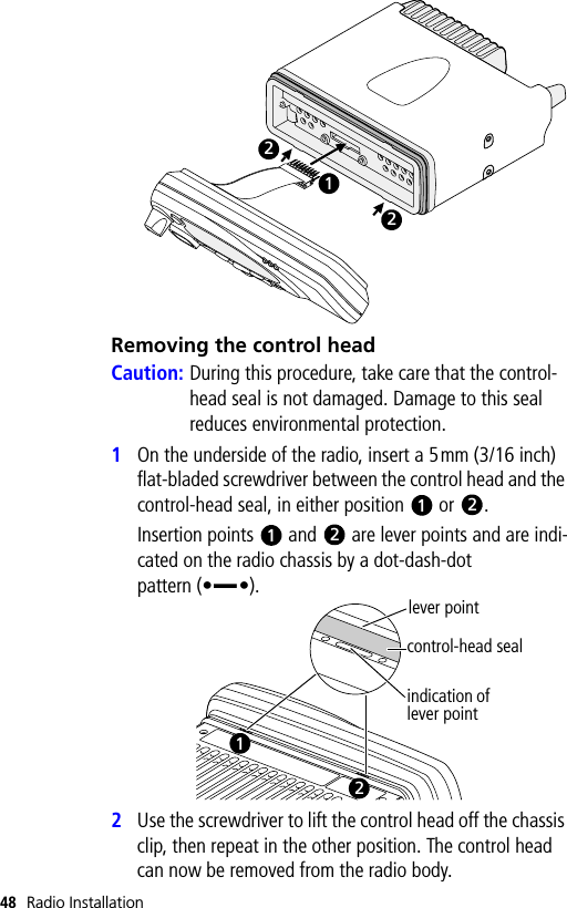
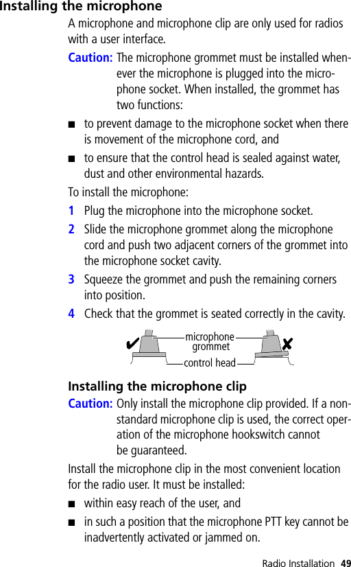
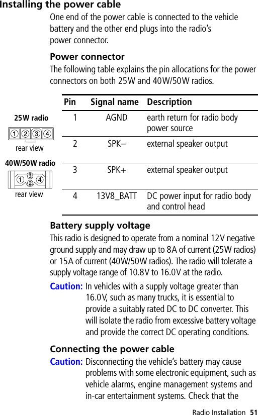
User Manual
Discussion / Help
Navigation