Tait TMAD1A Mobile Transceiver User Manual Service Manual

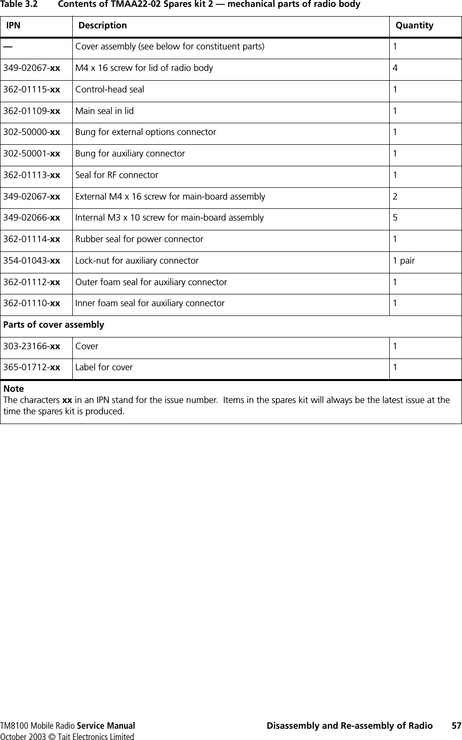
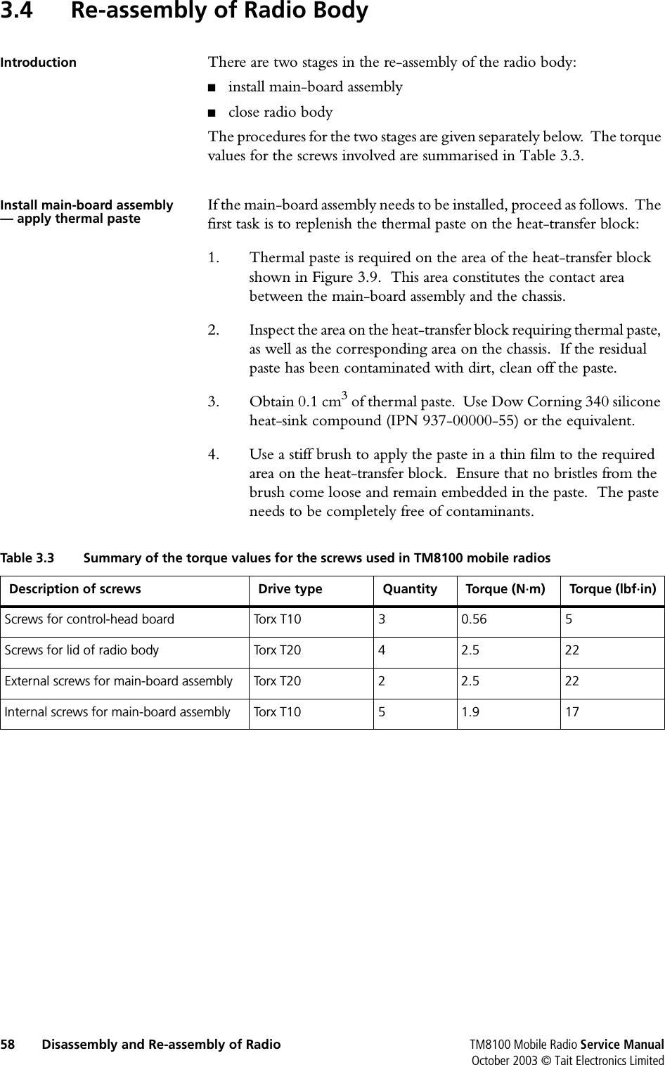
Tait Limited Mobile Transceiver Service Manual

Exhibit D Users Manual per 2 1033 c3

TM8000 mobilesTM8100 Mobile RadioService ManualMM8100-02-00-812 Version 1.01October 2003 © Tait Electronics Limited
2TM8100 Mobile Radio Service ManualOctober 2003 © Tait Electronics LimitedContact InformationTait Radio Communications http://www.taitworld.comCorporate Head OfficeNew ZealandTait Electronics LtdP.O. Box 1645ChristchurchNew ZealandE-mail:  info@taitworld.comWebsite:  http://www.taitworld.comTechnical Support:E-mail:  support@taitworld.comWebsite:  http://support.taitworld.comTait North AmericaRegional Head Office: United States of AmericaTait North America IncE-mail:  usa@taitworld.comCanadaTait North America IncE-mail:  canada@taitworld.comLatin AmericaTait Latin AmericaE-mail:  latinamerica@taitworld.comTait EuropeRegional Head Office: United KingdomTait Mobile Radio LtdE-mail:  teusales@tait.co.ukTait North AsiaRegional Head Office: Hong KongTait Mobile Radio (Hong Kong) LtdE-mail:  hongkong@taitworld.comBeijingTait Mobile Radio (Hong Kong) LtdE-mail:  beijing@taitworld.comTait South AsiaRegional Head Office: SingaporeTait Electronics (Far East) Pte LtdE-mail:  singapore@taitworld.comThailandTait Mobile Radio LtdE-mail:  thailand@taitworld.comTait OceaniaNew ZealandTait Communications LtdE-mail:  headoffice@tcl.tait.co.nzAustraliaTait Electronics (Aust) Pty LtdE-mail:  australia@taitworld.comNoteFor the addresses and telephone numbers of the above regional offices refer to the TaitWorld website.
TM8100 Mobile Radio Service Manual 3October 2003 © Tait Electronics LimitedTait General Software Licence AgreementThis legal document is an Agreement between you (the “Licensee”) and Tait Electronics Limited (“Tait”). By using any of the Software or Firmware items prior-installed in the related Tait product, included on this CD or downloaded from the Tait website, (hereinafter referred to as “the Software or Firmware”) you agree to be bound by the terms of this Agreement. If you do not agree to the terms of this Agreement, do not install and use any of the Software or Firmware. If you install and use any of the Software or Firmware that will be deemed to be acceptance of the terms of this licence agreement.The terms of this agreement shall apply subject only to any express written terms of agreement to the contrary between Tait and the Licensee.LicenceTAIT GRANTS TO YOU AS LICENSEE THE NON-EXCLUSIVE RIGHT TO USE THE SOFTWARE ORFIRMWARE ON A SINGLE MACHINE PROVIDED YOUMAY ONLY:1. COPY THE SOFTWARE OR FIRMWARE INTO ANYMACHINE READABLE OR PRINTED FORM FORBACKUP PURPOSES IN SUPPORT OF YOUR USE OFTHE PROGRAM ON THE SINGLE MACHINE (CERTAINPROGRAMS,HOWEVER,MAY INCLUDE MECHANISMSTO LIMIT OR INHIBIT COPYING,THEY ARE MARKED“COPY PROTECTED”), PROVIDED THE COPYRIGHTNOTICE MUST BE REPRODUCED AND INCLUDED ONANY SUCH COPY OF THE SOFTWARE OR FIRMWARE;AND / OR2. MERGE IT INTO ANOTHER PROGRAM FOR YOURUSE ON THE SINGLE MACHINE (ANY PORTION OFANY SOFTWARE OR FIRMWARE MERGED INTOANOTHER PROGRAM WILL CONTINUE TO BESUBJECT TO THE TERMS AND CONDITIONS OF THISAGREEMENT).THE LICENSEE MAY NOT DUPLICATE,MODIFY,REVERSE COMPILE OR REVERSE ASSEMBLE ANYSOFTWARE OR FIRMWARE IN WHOLE OR PART.Title to Software THIS AGREEMENT DOES NOT CONSTITUTE ACONTRACT OF SALE IN RELATION TO THESOFTWARE OR FIRMWARE SUPPLIED TO THELICENSEE.NOT WITHSTANDING THE LICENSEE MAYOWN THE MAGNETIC OR OTHER PHYSICAL MEDIAON WHICH THE SOFTWARE OR FIRMWARE WASORIGINALLY SUPPLIED,OR HAS SUBSEQUENTLYBEEN RECORDED OR FIXED,IT IS A FUNDAMENTALTERM OF THIS AGREEMENT THAT AT ALL TIMESTITLE AND OWNERSHIP OF THE SOFTWARE ORFIRMWARE,WHETHER ON THE ORIGINAL MEDIA OROTHERWISE,SHALL REMAIN VESTED IN TAIT ORTHIRD PARTIES WHO HAVE GRANTED LICENCES TOTAIT.Term and Termination THIS LICENCE SHALL BE EFFECTIVE UNTILTERMINATED IN ACCORDANCE WITH THEPROVISIONS OF THIS AGREEMENT.THE LICENSEEMAY TERMINATE THIS LICENCE AT ANY TIME BYDESTROYING ALL COPIES OF THE SOFTWARE ORFIRMWARE AND ASSOCIATED WRITTEN MATERIALS.THIS LICENCE WILL BE TERMINATEDAUTOMATICALLY AND WITHOUT NOTICE FROMTAIT IN THE EVENT THAT THE LICENSEE FAILS TOCOMPLY WITH ANY TERM OR CONDITION OF THISAGREEMENT.THE LICENSEE AGREES TO DESTROYALL COPIES OF THE SOFTWARE OR FIRMWARE ANDASSOCIATED WRITTEN MATERIALS IN THE EVENT OFSUCH TERMINATION.Limited Warranty THE SOFTWARE OR FIRMWARE IS SUPPLIED BY TAITAND ACCEPTED BY THE LICENSEE “AS IS”WITHOUTWARRANTY OF ANY KIND EITHER EXPRESSED ORIMPLIED,INCLUDING BUT NOT BEING LIMITED TOANY IMPLIED WARRANTIES AS TOMERCHANTABILITY OR FITNESS FOR ANYPARTICULAR PURPOSE.THE LICENSEEACKNOWLEDGES THAT THE SOFTWARE ORFIRMWARE IS USED BY IT IN BUSINESS ANDACCORDINGLY TO THE MAXIMUM EXTENTPERMITTED BY LAW NO TERMS OR WARRANTIESWHICH ARE IMPLIED BY LEGISLATION SHALL APPLYTO THIS AGREEMENT.TAIT DOES NOT WARRANTTHAT THE FUNCTIONS CONTAINED IN THESOFTWARE OR FIRMWARE WILL MEET THELICENSEE’S REQUIREMENTS OR THAT THEOPERATION OF THE SOFTWARE OR FIRMWARE WILLBE UNINTERRUPTED OR ERROR-FREE.
4TM8100 Mobile Radio Service ManualOctober 2003 © Tait Electronics LimitedExclusion of LiabilityTAIT’S ENTIRE LIABILITY AND THE LICENSEE’SEXCLUSIVE REMEDY SHALL BE THE FOLLOWING:1. IN NO CIRCUMSTANCES SHALL TAIT BE UNDERANY LIABILITY TO THE LICENSEE,OR ANY OTHERPERSON WHATSOEVER,FOR ANY DIRECT OR CON-SEQUENTIAL DAMAGE ARISING OUT OF OR IN CON-NECTION WITH ANY USE OR INABILITY OF USINGTHE SOFTWARE OR FIRMWARE.2. TAIT WARRANTS THE OPERATION OF THESOFTWARE OR FIRMWARE ONLY WITH THEOPERATING SYSTEM FOR WHICH IT WAS DESIGNED.USE OF THE SOFTWARE OR FIRMWARE WITH ANOPERATING SYSTEM OTHER THAN THAT FORWHICH IT WAS DESIGNED MAY NOT BE SUPPORTEDBY TAIT,UNLESS OTHERWISE EXPRESSLY AGREED BYTAIT.GeneralTHE LICENSEE CONFIRMS THAT IT SHALL COMPLYWITH THE PROVISIONS OF LAW IN RELATION TO THESOFTWARE OR FIRMWARE.Law and Jurisdiction THIS AGREEMENT SHALL BE SUBJECT TO ANDCONSTRUED IN ACCORDANCE WITH NEW ZEALANDLAW AND DISPUTES BETWEEN THE PARTIESCONCERNING THE PROVISIONS HEREOF SHALL BEDETERMINED BY THE NEW ZEALAND COURTS OFLAW.PROVIDED HOWEVER TAIT MAY AT ITSELECTION BRING PROCEEDINGS FOR BREACH OFTHE TERMS HEREOF OR FOR THE ENFORCEMENTOF ANY JUDGEMENT IN RELATION TO A BREACH OFTHE TERMS HEREOF IN ANY JURISDICTION TAITCONSIDERS FIT FOR THE PURPOSE OF ENSURINGCOMPLIANCE WITH THE TERMS HEREOF OROBTAINING RELIEF FOR BREACH OF THE TERMSHEREOF.No Dealings THE LICENSEE MAY NOT SUBLICENSE,ASSIGN ORTRANSFER THE LICENCE OR THE PROGRAM EXCEPTAS EXPRESSLY PROVIDED IN THIS AGREEMENT.ANYATTEMPT OTHERWISE TO SUBLICENSE,ASSIGN ORTRANSFER ANY OF THE RIGHTS,DUTIES OROBLIGATIONS HEREUNDER IS VOID.No Other Terms THE LICENSEE ACKNOWLEDGES THAT IT HAS READTHIS AGREEMENT,UNDERSTANDS IT AND AGREESTO BE BOUND BY ITS TERMS AND CONDITIONS.THELICENSEE FURTHER AGREES THAT SUBJECT ONLYTO ANY EXPRESS WRITTEN TERMS OF AGREEMENTTO THE CONTRARY BETWEEN TAIT AND THELICENSEE THIS IS THE COMPLETE AND EXCLUSIVESTATEMENT OF THE AGREEMENT BETWEEN IT ANDTAIT IN RELATION TO THE SOFTWARE ORFIRMWARE WHICH SUPERSEDES ANY PROPOSAL ORPRIOR AGREEMENT,ORAL OR WRITTEN AND ANYOTHER COMMUNICATIONS BETWEEN THE LICENSEEAND TAIT RELATING TO THE SOFTWARE ORFIRMWARE.
TM8100 Mobile Radio Service Manual 5October 2003  © Tait Electronics LimitedContentsPreface. . . . . . . . . . . . . . . . . . . . . . . . . . . . . . . . . . . . . . . . . . . . . . . . . . . . . . . . . . . . .6Notes for Readers  . . . . . . . . . . . . . . . . . . . . . . . . . . . . . . . . . . . . . . . . . . . . . . . . . . . . 7Typographical Conventions. . . . . . . . . . . . . . . . . . . . . . . . . . . . . . . . . . . . . . . . . . . . . . 8Associated Documents  . . . . . . . . . . . . . . . . . . . . . . . . . . . . . . . . . . . . . . . . . . . . . . . . . 9Amendment Record. . . . . . . . . . . . . . . . . . . . . . . . . . . . . . . . . . . . . . . . . . . . . . . . . . 10List of Acronyms  . . . . . . . . . . . . . . . . . . . . . . . . . . . . . . . . . . . . . . . . . . . . . . . . . . . . 111  Introduction . . . . . . . . . . . . . . . . . . . . . . . . . . . . . . . . . . . . . . . . . . . . . . .  131.1  TM8100 Mobile Radio System  . . . . . . . . . . . . . . . . . . . . . . . . . . . . . . . . . . . . . . 131.2  Radio Body. . . . . . . . . . . . . . . . . . . . . . . . . . . . . . . . . . . . . . . . . . . . . . . . . . . . . 191.3  Control Head  . . . . . . . . . . . . . . . . . . . . . . . . . . . . . . . . . . . . . . . . . . . . . . . . . . . 211.4  Repair Levels. . . . . . . . . . . . . . . . . . . . . . . . . . . . . . . . . . . . . . . . . . . . . . . . . . . . 221.5  Product Codes. . . . . . . . . . . . . . . . . . . . . . . . . . . . . . . . . . . . . . . . . . . . . . . . . . . 232  General Description . . . . . . . . . . . . . . . . . . . . . . . . . . . . . . . . . . . . . . . . . .  272.1  Architecture of Radio  . . . . . . . . . . . . . . . . . . . . . . . . . . . . . . . . . . . . . . . . . . . . . 272.2  Operation of Control-head Circuitry . . . . . . . . . . . . . . . . . . . . . . . . . . . . . . . . . . 292.3  Operation in Receive Mode. . . . . . . . . . . . . . . . . . . . . . . . . . . . . . . . . . . . . . . . . 312.4  Operation in Transmit Mode . . . . . . . . . . . . . . . . . . . . . . . . . . . . . . . . . . . . . . . . 342.5  Operation of Frequency Synthesizer . . . . . . . . . . . . . . . . . . . . . . . . . . . . . . . . . . . 373  Disassembly and Re-assembly of Radio  . . . . . . . . . . . . . . . . . . . . . . . . . . . .  393.1  Detachment of Control Head . . . . . . . . . . . . . . . . . . . . . . . . . . . . . . . . . . . . . . . . 413.2  Disassembly of Control Head . . . . . . . . . . . . . . . . . . . . . . . . . . . . . . . . . . . . . . . . 453.3  Disassembly of Radio Body . . . . . . . . . . . . . . . . . . . . . . . . . . . . . . . . . . . . . . . . . 513.4  Re-assembly of Radio Body. . . . . . . . . . . . . . . . . . . . . . . . . . . . . . . . . . . . . . . . . 583.5  Re-assembly and Attachment of Control Head . . . . . . . . . . . . . . . . . . . . . . . . . . . 61
6TM8100 Mobile Radio Service ManualOctober 2003 © Tait Electronics LimitedPrefaceScope of service manual This manual provides information to service technicians for carrying out level-1 repairs of TM8100 mobile radios.  Level-1 repairs entail the replacement of faulty parts and circuit boards.The manual does not cover level-2 repairs (repair of circuit boards, with the exception of certain special items on the boards) and level-3 repairs (repair of the special items).The servicing procedures are moreover limited to the control head and radio body of TM8100 mobile radios.  Servicing of all accessories associated with the radio is covered in the accessories manual.Summary of service manual The service manual is divided into three sections.  The first section introduces the radio.  The main products making up the radio system are identified (in particular, the control head and radio body), the repair levels are discussed, and the product codes of the control head and radio body are given.In the second section the functioning of the radio is described.  The description is limited to the control head and radio body.  The architecture of the radio, the operation of the control-head circuitry, the functioning of the radio in the receive and transmit modes, and the operation of the frequency synthesizer are described.The third section provides information regarding the level-1 repair procedures.  The information is mainly limited to the procedures for disassembling and re-assembling the radio.  Only a brief outline is given of the overall repair procedures themselves.
TM8100 Mobile Radio Service Manual 7October 2003 © Tait Electronics LimitedNotes for ReadersEnquiries and comments Any enquiries regarding this manual or the equipment that it describes, as well as any comments, suggestions and notifications of errors, should be addressed by e-mail to Technical Support (support@taitworld.com)or to the Technical Support Manager, Tait Electronics Limited, PO Box 1645, Christchurch, New Zealand.  Orders for this manual can be placed with your Tait Dealer.Updates of manualand equipment In the interests of improving the performance, reliability or servicing of the equipment, Tait Electronics Limited reserves the right to upgrade the equipment or update this manual or both without prior notice.Copyright All information contained in this manual is the property of Tait Electronics Limited.  All rights are reserved.  This manual may not, in whole or in part, be copied, photocopied, reproduced, translated, stored, or reduced to any electronic medium or machine-readable form, without prior written permission from Tait Electronics Limited.  All trade names referenced are the service mark, trade mark, or registered trade mark of the respective manufacturers.Disclaimer There are no warranties extended or granted by this manual.  Tait Electronics Limited accepts no responsibility for damage arising from use of the information contained in the manual or of the equipment and software it describes.  It is the responsibility of the user to ensure that use of such information, equipment and software complies with the laws, rules and regulations of the applicable jurisdictions.
8TM8100 Mobile Radio Service ManualOctober 2003 © Tait Electronics LimitedTypographical ConventionsConventions and alerts In this manual the names of electrical signals are typed in small capitals using the standard sans-serif font of the document.  For example:TX INHIBITAlert notices that appear in the manual are selected from whichever of the following are appropriate.  These alert notices are in accordance with the ANSI definitions.Warning!! This alert notice is used when there is a potential risk of death or serious injury.Caution This alert notice is used when there is a risk of minor to moderate injury to people.Important This alert notice is used to warn about the risk of equipment damage or malfunction.Note This alert notice is used to highlight information that is required to ensure that procedures are performed correctly.
TM8100 Mobile Radio Service Manual 9October 2003 © Tait Electronics LimitedAssociated DocumentsBasic manuals Together with this service manual, the following manuals are of concern to service technicians.  The pair of digits in the third field of the document product code indicates the language of the document — 00 indicates an English and 03 a multi-lingual document.MM8100-00-03-804TM8100 mobile radio — User’s guideMMAA00-00-00-812TM8100 mobile radio — Accessories manualPCB information packages Information on the circuit boards is supplied in the following separate documents.  The information consists of the BOMs (parts lists), grid reference indexes, PCB layouts, and circuit diagrams.MMAB12-H5-00-814Main board (H5/H6) — PCB information packageMMAB12-B1-00-814Main board (B1) — PCB information packageMMAC20-00-00-814Control-head board — PCB information package3DK manuals The following manuals are mainly of concern to third-party developers.  The manuals are supplied in soft-copy form on a 3DK resource CD.MMAA30-00-00-807TM8000 3DK hardware developer’s kit — Application manualMMAA30-02-00-429TM8000 3DK application board — Software programmer’s manualMMAA30-02-00-812TM8000 3DK application board — Service manualMM8100-00-00-441TM8100 Computer-controlled data interface — Protocol definition
10 TM8100 Mobile Radio Service ManualOctober 2003 © Tait Electronics LimitedAmendment RecordVersion Publication date Amended sections and pages1.00 September 2003 First release1.01 October 2003 Alert notice added in Section 3Figures 3.5 to 3.8 updated
TM8100 Mobile Radio Service Manual 11October 2003 © Tait Electronics LimitedList of Acronyms3DK Third-party Developer’s KitAC Alternating CurrentACP Adjacent Channel PowerADC Analogue-to-digital ConverterAGC Automatic Gain ControlALC Automatic Level ControlASC Accredited Service CentreBOM Bill of MaterialsCODEC Coder-decoderCSO Customer Service OrganisationDAC Digital-to-analogue ConverterDC Direct CurrentDIN Deutsche Industrie NormDSP Digital Signal ProcessorDTMF Dual-tone Multi-frequencyFCL Frequency Control LoopFPGA Field-programmable Gate ArrayIPN Internal Part NumberIC Integrated CircuitIF Intermediate FrequencyIQ In-phase and QuadratureISC International Service CentreLCD Liquid-crystal DisplayLED Light-emitting DiodeLO Local OscillatorPA Power AmplifierPCB Printed Circuit BoardPLL Phase-locked LoopRF Radio FrequencyRSSI Received Signal Strength IndicationSMT Surface-mount TechnologyTCXO Temperature-compensated Crystal OscillatorTEL Tait Electronics LimitedUHF Ultra-high FrequencyVCO Voltage-controlled OscillatorVCXO Voltage-controlled Crystal OscillatorVHF Very High Frequency
12 TM8100 Mobile Radio Service ManualOctober 2003 © Tait Electronics Limited
TM8100 Mobile Radio Service Manual Introduction 13October 2003 © Tait Electronics Limited1 IntroductionScope of section This section introduces the TM8100 mobile radio system.  The main items making up the system are first introduced.  There follows additional information on the radio body and control head — the two items that are the prime concern of the service manual.  Next is a discussion of the repair levels that govern the servicing of the radio body and control head.  The section concludes with an explanation of the product codes for these items.1.1 TM8100 Mobile Radio SystemMain items of system The TM8100 mobile radio system is a high-performance microprocessor-controlled transceiver with a comprehensive range of accessories.  The system is designed primarily for installation in vehicles but can also be used in desktop, remote-monitoring and similar applications.  The system consists of the following main items:■radio body■control head■audio accessories■mounting for radio■desktop power supply (optional)The service manual covers the servicing of the radio body and control head only.  The accessories manual covers servicing of all the remaining items.Specifications for system The specifications for the system are not given in this manual, but will be found instead on the TaitWorld website in the area reserved for TM8000 products.  This ensures that the latest specification data will always be available to service technicians.Radio body The radio body contains the transmitter, receiver and microprocessor circuitry.  The radio body also allows for the fitting of an internal options board to provide additional functions.  There are three standard external connectors on the radio body: an RF connector, power connector, and auxiliary connector.  If an internal options board is fitted, there might or might not be an associated external options connector.  The auxiliary and external options connectors allow for the connection of various external devices.
14 Introduction TM8100 Mobile Radio Service ManualOctober 2003 © Tait Electronics LimitedFigure 1.1 Illustrations of the TM8115 mobile radio showing both the front and rear
TM8100 Mobile Radio Service Manual Introduction 15October 2003 © Tait Electronics LimitedControl head The control head is attached to the radio body.  There is a choice of two control heads:■two-digit-display control head■blank control headThe two-digit display control head provides the interface with the radio user and includes a socket for the connection of a microphone.  The blank control head has no user interface but has a single external connector called the programming connector; this is typically used for programming and monitoring purposes.  The radio is designated TM8115 with the two-digit-display control head and TM8105 with the blank control head.  Illustrations of these radios are given in Figure 1.1 and Figure 1.2.Audio accessories One or more audio accessories may be connected to the control head and radio body.  A microphone is the accessory usually required; other accessories that are available are a handset, high-power remote speaker, and hands-free kit.  Various external devices may also be connected.  The user’s guide and accessories manual describe the audio accessories.Figure 1.2 Illustration of the front of the TM8105 mobile radio
16 Introduction TM8100 Mobile Radio Service ManualOctober 2003 © Tait Electronics LimitedFigure 1.3 Block diagram of an example installation of the TM8115 mobile radio in a vehicledwlsMICROPHONECONNECTORMICRO-PHONEHANGERPLATEEXTERNALDEVICEHANDS-FREEKITVEHICLEBATTERYFUSESHIGH-POWERREMOTESPEAKERPOWERCONNECTORAUXILIARYCONNECTOREXTERNAL OPTIONSCONNECTORRFCONNECTORRF ANTENNAMOUNTINGCONTROLHEAD RADIO BODYRADIO SYSTEM
TM8100 Mobile Radio Service Manual Introduction 17October 2003 © Tait Electronics LimitedFigure 1.4 Block diagram of an example desktop installation of the TM8115 mobile radiodwlsMICROPHONECONNECTORHANDSETORDESKTOPMICRO-PHONERADIO SYSTEMDESKTOP POWER SUPPLYCONTROLHEAD RADIO BODYPOWERCONNECTORAUXILIARYCONNECTOREXTERNAL OPTIONSCONNECTORRFCONNECTORRF ANTENNAEXTERNALDEVICEBACK-UPBATTERYAC MAINS
18 Introduction TM8100 Mobile Radio Service ManualOctober 2003 © Tait Electronics LimitedFigure 1.5 Block diagram of an example installation of the TM8105 mobile radio in a vehicledwlsEXTERNALDEVICEPROGRAMMINGCONNECTORMOUNTINGBLANKCONTROLHEADRADIO BODYRADIO SYSTEMVEHICLEBATTERYPOWERCONNECTORAUXILIARYCONNECTOREXTERNAL OPTIONSCONNECTORRFCONNECTOREXTERNALDEVICEEXTERNALDEVICEFUSESRF ANTENNA
TM8100 Mobile Radio Service Manual Introduction 19October 2003 © Tait Electronics LimitedInstallation kits anddesktop power supply The mounting hardware for the radio is in the form of a U-cradle.  It is supplied in an installation kit and provides for the installation of the radio in a vehicle.  Alternatively, the radio might be needed for desktop use, in which case a desktop power supply is required.  In some desktop installations the U-cradle is used to attach the radio to the power supply.  The user’s guide and accessories manual describe the installation kit.Block diagrams of system The block diagrams of Figure 1.3 to Figure 1.5 illustrate possible configurations of the radio system.  Figure 1.3 and Figure 1.4 show example installations of the TM8115 radio (with two-digit-display control head) in a vehicle and on a desktop.  Figure 1.5 shows an example of the TM8105 radio (with blank control head) installed in a vehicle.  Different audio accessories are shown connected to the radio.  The hands-free kit is connected to the auxiliary connector, and the remote speaker to the power connector.  The accessories that may be connected to the microphone connector include the rugged microphone, as well as a DTMF microphone, desktop microphone, and handset.1.2 Radio BodyMain, digital andinternal options boards The radio body consists of a rectangular case — or chassis — with a lid.  The case houses a main board with the receiver and transmitter circuitry, and a digital board with the microprocessor that controls the radio.  There are different main boards available covering different frequency bands and with different RF performances; refer to the product codes in Figure 1.8.  The digital board is reflow-soldered to the main board.  There is space in the lid for an optional internal options board.  The essentials of the arrangement are illustrated in the block diagram of Figure 1.6.Main-board assembly The rear edge of the main board is attached to a heat-transfer block.  The block is in thermal contact with the rear of the case, where there are cooling fins for heat dissipation.  Heat from the output stage of the transmitter is conducted via the heat-transfer block to the rear and radiated from the cooling fins.  (The lower surface of the case is ridged to augment the dissipation of heat.)  The RF, auxiliary and power connectors are fixed to the rear of the main board.  They project through apertures in the heat-transfer block and the rear of the case.  The main board, digital board, and heat-transfer block constitute a separate unit called the main-board assembly.Internal options boards Either Tait-designed or custom internal options boards may be fitted in the radio body.    Full details of the boards are given in the accessories and 3DK manuals.  Any internal options board that is fitted might or might not include an external options connector.  If included, the connector will project through an aperture in the rear of the lid.  If there is no connector, the aperture is sealed with a bung.
20 Introduction TM8100 Mobile Radio Service ManualOctober 2003 © Tait Electronics LimitedFigure 1.6 Block diagram of the radio body and control head of the TM8115 mobile radio
TM8100 Mobile Radio Service Manual Introduction 21October 2003 © Tait Electronics LimitedInternal connections There are three sets of internal connections to the main board; these use the following connectors:■debug connector■control-head connector■internal options connectorThe debug connector is for Factory use only.  The control-head connector is on the front edge of the main board; it is used to connect a control-head loom from the control head to the main board.  The internal options connector is required when an internal options board is fitted; it is used to connect an options loom between the two boards.1.3 Control HeadIntroduction The control head clips securely to the front of the radio body.  The control-head loom between the two is enclosed in the space between them.  For badging and branding purposes there are both a logo and a label for the product model code on the front panel.  The control head may also be left unbadged.  The essentials of the two-digit-display control head are shown in the block diagram of Figure 1.6.Two-digit-display control head The front panel of the two-digit-display control head is fitted with the controls and indicators needed by the radio user; these comprise:■LCD screen■indicator LEDs■volume control■on/off key■function keys■channel-selection keysIn addition, there are the microphone connector and an internal speaker.  The necessary circuitry for the above items is mounted on a control-head board fitted behind the front panel.  The volume-control potentiometer is fixed to the board; so is a control-head connector, which is used for the control-head loom between the control head and radio body.Options for control head The two-digit-display control head allows for an optional concealed microphone or the use of a dynamic microphone.  (A concealed microphone is fitted behind the front panel next to the speaker.)  With either option a separate circuit board is required for the microphone.  This board is connected to the control-head board by means of two connectors; the plugs of the connectors are mounted on the latter board and the sockets on the former.  Full details of the optional microphones and circuit board are given in the accessories manual.
22 Introduction TM8100 Mobile Radio Service ManualOctober 2003 © Tait Electronics LimitedBlank control head The blank control head has none of the features of the two-digit-display control head.  The front panel of the blank control head is fitted only with the single programming connector.  The control-head loom is permanently fixed to the rear of the programming connector.  The space inside the control head can be used for the fitting of an optional third-party circuit board, but is otherwise empty.1.4 Repair LevelsLevel-1 repairs The repairs that can be carried out on the TM8100 mobile radio are grouped into categories — or levels — of increasing complexity.  This manual covers only level-1 repairs, which comprise the following:■replacement of control-head board■replacement of main-board assembly■replacement of other partsThe last-named parts include the connectors and volume-control potentiometer on the control-head board, but not the connectors on the main board.Level-2 repairs It is important to distinguish level-1 repairs from the higher-level repairs, which require greater skills and resources.  Thus, level-2 repairs comprise the following:■repair of control-head board■repair of main-board assembly, excluding special itemsThese repairs entail the replacement of faulty SMT components on the boards, as well as the connectors on the main board.  The special items are the digital board and certain components on the main board.  (Repairs of the special items are level-3 repairs.)Service centres The service centres that carry out repairs of TM8100 mobile radios can be divided into three categories:■Dealers and Customers with appropriate facilities■ASCs, including CSOs■TEL and ISCASCs, the ISC and TEL may carry out both level-1 and level-2 repairs.  These are moreover the only service centres that may repair a radio that is still under warranty — any repair by a non-accredited service centre will void the warranty.  After the expiry of the warranty, Dealers and Customers with appropriate facilities may also carry out level-1 repairs, but are strongly advised not to attempt level-2 repairs.  Contact Technical Support for details of the process by which service centres may achieve accreditation.
TM8100 Mobile Radio Service Manual Introduction 23October 2003 © Tait Electronics LimitedRestrictions regardinglevel-3 repairs Only TEL and the ISC should carry out level-3 repairs.  The level of technology employed in the TM8100 generation of radios is an order of magnitude greater than in earlier generations.  This greater sophistication demands special equipment and techniques for level-3 repairs.  Although other service centres are strongly advised not to attempt such repairs, those with sufficient resources and skilled technicians may wish to do so.  These service centres should contact Technical Support for assistance and for the necessary documentation.  TEL does not offer accreditation for level-3 repairs to any service centres other than the ISC.1.5 Product CodesIntroduction This subsection describes the product codes used to identify different products of the mobile radio product line.  The product-code scheme in general is first explained, and then the product codes for the radio body and control head in particular.  The purpose is solely to enable service technicians to identify the radio body and control head of a radio that has been delivered for repair.Figure 1.7 Scheme for the product codes assigned to products of the mobile radio product line
24 Introduction TM8100 Mobile Radio Service ManualOctober 2003 © Tait Electronics LimitedLimitations on useof product codes The product codes discussed in this subsection are those in use at the time of publication.  For up-to-date information refer to the TaitWorld website.  The explanations of the product codes are to aid identification only, and are not to be used as the basis for sales orders.  There are two reasons for this:  Firstly, an arbitrarily-constructed product code might apply to a product that, for compliance reasons, is restricted to certain markets.  Secondly, a product with such a product code might not even exist.General scheme forproduct codes Individual products of the mobile radio product line are identified by product codes with the format:TMabcc–ddeewhere a and b are uppercase letters representing the product family and category of product respectively, and cc,dd and ee are characters that identify the specific product.  The characters ee are applicable to the radio body only and identify different options.  The product code scheme is summarised in Figure 1.7.Figure 1.8 Scheme for the product codes currently in use for the radio body of TM8100 mobile radios
TM8100 Mobile Radio Service Manual Introduction 25October 2003 © Tait Electronics LimitedProduct familiesand categories Examples of different product families within the mobile radio product line are the T700, T2000 and TM8100 radios.  The TM8100 family is however the first to which the above product-code scheme applies.  Examples of different product categories are radio bodies, control heads, and accessories.  These are the only categories identified to date.  The product codes for the TM8100 radio body and control head are discussed below; those for the accessory items are described in the accessories manual.Product codesfor radio body The product codes for the TM8100 radio body have the format:TMABab–ccddwhere a identifies the architecture of the digital board, b identifies the RF performance, cc is the letter-digit combination identifying the frequency band, and dd identifies any options selected.  The characters dd are set to 00 for the default radio with no options added.  For universal options available to all Customers, the digits 01 to 99 are used for dd.  For custom options implemented for particular Customers, the letters AA to ZZ are used.  The digits and letters identifying the universal and custom options are assigned sequentially.  Figure 1.8 illustrates the product codes in use at the time of publication.Figure 1.9 Scheme for the product codes currently in use for the control head of TM8100 mobile radios
26 Introduction TM8100 Mobile Radio Service ManualOctober 2003 © Tait Electronics LimitedProduct codesfor control head The product codes for the TM8100 control head have the format:TMACab–ccwhere a identifies the type of control head, b identifies any options selected, and cc identifies badging and branding options.  By type is meant whether the control head is a blank or two-digit-display control head; allowance is made for additional types in the future.  Only the digits 1 to 9 are allowed for a (0 is not used), and the digits 0 to 9 for b;the latter is set to 0 when no options are added.  Both letters and digits may be used for cc.  The default for cc is 0T; on the two-digit-display control head the Tait logo is then displayed next to the LCD screen, and the product model code TM8115 is displayed above the speaker grill.  Figure 1.9 illustrates the product codes in use at the time of publication.
TM8100 Mobile Radio Service Manual General Description 27October 2003 © Tait Electronics Limited2 General DescriptionScope of section This section comprises a general description of the radio body and control head of TM8100 mobile radios.  Firstly, the architecture of the radio is described.  Secondly, the operation of the control-head circuitry is summarised.  Finally, the principles of operation of the radio are given in three separate subsections.2.1 Architecture of RadioIntroduction In this subsection the architecture of the radio is described.  The different circuit modules of the control-head, main and digital boards introduced in Section 1 are identified.  The optional circuit boards mentioned in Section 1 are covered in other manuals.Control head The two-digit-display control head houses a control-head board with the circuitry needed for the controls and indicators on the front panel.  There is provision for an optional board for use with dynamic microphones or with a concealed microphone inside the control head.  There is also provision for the fitting of an optional third-party circuit board in the blank control head.The operation of the control-head board is summarised in Subsection 2.2.  The circuit board for concealed and dynamic microphones is described in the accessories manual.  The fitting of third-party circuit boards in the blank control head is discussed in the application manual for 3DK hardware developers.Radio body The radio body houses a main board with the transmitter, receiver and associated circuitry, and a digital board with the microprocessor and associated circuitry.  The digital board is reflow-soldered to the main board.  There is also provision for an internal options board to be connected to the main board.The different circuit modules of the main board are discussed below and the operation of the circuitry is described in Subsection 2.3 to Subsection 2.5.  The different internal options boards are discussed in the accessories manual and the 3DK manuals.
28 General Description TM8100 Mobile Radio Service ManualOctober 2003 © Tait Electronics LimitedFigure 2.1 Block diagram of the main board of the radio body
TM8100 Mobile Radio Service Manual General Description 29October 2003 © Tait Electronics LimitedModules of main board The control-head, main and digital boards, and the connectors on the boards, are illustrated in Figure 1.6 of Section 1.  Figure 2.1 is a block diagram showing the main and digital boards and the circuit modules of the main board.  These modules are:■transmitter■receiver■frequency synthesizer■CODEC and audio circuitry■power supply■interface circuitrySoftware plays a prominent role in the functioning of the TM8100 radio.  For describing the operation of the radio the software must be included with the above modules.  This is considered further below.Operation of radio Figure 2.2 is a simplified block diagram of the transceiver architecture showing the hardware modules integrated with the software modules.  The same DSP device includes the software that controls the transceiver and the software constituting the digital-signal-processing blocks in Figure 2.2.  The operation of the radio is then best described with reference to Figure 2.2 and with a division into the following three parts:■operation in receive mode■operation in transmit mode■operation of frequency synthesizerOperational descriptions of these three parts are given in Subsection 2.3 to Subsection 2.5 respectively.2.2 Operation of Control-head CircuitryUser interface In this subsection the operation of the control-head circuitry is summarised.  The standard control head provides a user interface consisting of:■two-digit seven-segment LCD■up and down channel-selection keys■four programmable function keys■on/off push-button key■LED indicators■volume control■internal speaker■microphone connectorThe microphone connector may also be used for the connection of a handset or programming lead.  If required, a concealed microphone may be fitted inside the control head.
30 General Description TM8100 Mobile Radio Service ManualOctober 2003 © Tait Electronics LimitedFigure 2.2 Architecture of the TM8100 transceiver
TM8100 Mobile Radio Service Manual General Description 31October 2003 © Tait Electronics LimitedConnectors and circuit boards There is an 18-way electrical interface between the control head and radio body.  The physical connection is via an 18-way loom.  The control head normally contains a single PCB assembly called the control-head board.  If a dynamic microphone is used or a concealed microphone fitted, a small circuit board must be mounted on the control-head board.  The added board has the necessary amplification, filtering and switching functions.  The internal speaker is connected to the control-head board via a lead with a mating connector so that it can be easily disconnected.Control-head board The control-head board does not include a microprocessor.  A synchronous bi-directional serial interface provides communication of key status, LCD and LED-indicator data between the radio body and the control head.  On the control-head board the serial data are converted to or from parallel form by a number of shift registers for the keys and indicators.  For the LCD, the serial data are fed to a driver IC that converts the serial data to a form suitable for the LCD itself.  The keys are scanned and the LCD and LED indicators updated approximately every 50 ms.2.3 Operation in Receive ModeReceive path In this subsection the functioning of the radio in the receive mode is described.  As shown in Figure 2.2, the receive path exists in three different domains:■hardware■custom logic■DSPThe front-end hardware amplifies and image-filters the received RF spectrum, then down-converts the desired channel frequency to a first intermediate frequency IF1 of 45.1 MHz (UHF) or 21.4 MHz (VHF) where coarse channel filtering is performed.  The first LO signal is obtained from the frequency synthesizer.  The output of the first IF is then down-converted using an image-reject mixer to a low IF of 64 kHz.Quadrature demodulator The LO for the image-reject mixer (quadrature demodulator) is synthesized and uses the TCXO as a reference.  This ensures good centring of the IF filters and more consistent group-delay performance.  The quadrature demodulator device has an internal frequency division of 2 so the second LO operates at 2 x (IF1+ 64 kHz).  The quadrature output from this mixer is fed to a pair of ADCs with high dynamic range where it is oversampled at 256 kHz and fed to the custom logic device.
32 General Description TM8100 Mobile Radio Service ManualOctober 2003 © Tait Electronics LimitedCustom logic The remainder of the channel filtering is performed in custom logic.  Different filter shapes are possible to accommodate the various channel spacings and data requirements.  These filters provide the bulk of adjacent channel selectivity for narrow-band operation.  Each filter has a linear phase response so that good group-delay performance for data is achieved.  The filters also decimate the sample rate down to 48 kHz.  Custom logic also performs demodulation, which is multiplexed along with AGC and amplitude data and fed via a single synchronous serial port to the DSP.  The stream is demultiplexed and the demodulation data stream processed further to meet audio requirements.Automatic gain control The AGC is used to limit the maximum signal level applied to the image-reject mixer and ADCs in order to meet the requirements for intermodulation and selectivity performance.  Hardware gain control is performed by a variable gain amplifier within the quadrature demodulator device driven by a 10-bit DAC.   Information about the signal level is obtained from the IQ data output stream from the ADCs.  The control loop is completed within custom logic.  The AGC will begin to reduce gain when the combined signal power of the wanted signal and first adjacent channels is greater than about -70 dBm.  In the presence of a strong adjacent-channel signal it is therefore possible that the AGC may start acting when the wanted signal is well below -70 dBm.Noise squelch The noise squelch process resides in the DSP.  The noise content above and adjacent to the voice band is measured and compared with a preset threshold.  When a wanted signal is present, out-of-band noise content is reduced and, if below the preset threshold, is indicated as a valid desired signal.Noise blanking Provision has been made for an optional noise blanker to remove common sources of electrical interference such as vehicle ignition noise.  The noise blanker functions by sampling the RF input to the receiver for impulse noise and momentarily disconnecting the first LO for the duration of the impulse.  The response time of the noise blanker is very fast (tens of nanoseconds) and is quicker than the time taken for the RF signal to pass through the front-end hardware, so that the LO is disabled before the spike reaches the IF stage where it could cause crystal filter ring.  The noise blanker is fitted as standard for the VHF band.Monitoring The lock-detect signal of the second LO synthesizer is monitored at least every 100 ms.  If the PLL fails to indicate lock within 10 ms of programming, an error is reported by the control software.  If an out-of-lock condition occurs during run-time, then an audible indication will be given and recovery repeatedly attempted.
TM8100 Mobile Radio Service Manual General Description 33October 2003 © Tait Electronics LimitedCalibration The following items within the receiver path are calibrated:■Front-end tuning■AGC■Noise squelch■RSSIInformation on the calibration of these items is given in the on-line help facility of the calibration application.Audio processing Raw demodulated data from the receiver is processed within the DSP.  The sample rate at this point is 48000 samples per second with signal bandwidth limited only by the IF filtering.  Scaling (dependent on the bandwidth of the RF channel) and noise-peak limiting are then applied to normalise the signal level for the remaining audio processing.  The sample rate is decimated to 8000 samples per second and then low-pass filtered at 3 kHz, before being passed to the subaudible decoders and on for further filtering in the main path.  High-pass filtering is then applied to remove the subaudible signalling and rumble from the audio signal.  The filter cut frequency is made higher when subaudible signalling is expected compared to when it is not.  This allows full low-frequency audio response on non-subaudible channels.Signal source for speaker The output of the high-pass filter is where in-band signalling decoders obtain their input signal.  The signal is then de-emphasised.  The next process in the chain is a multiplexer to select a signal source to feed the main path to the speaker.  The sources are as follows:■receive path■confidence-tone generator■transmit confidence side-toneThe confidence-tone generator is activated for such events as key-presses or alarms; the level from this block is a fixed proportion (in the order of -10 dB) relative to full scale in the receive path.  Regarding the transmit confidence side-tone, the output of the transmit signalling encoders can be fed to the speaker to give the user confidence that the signalling message is being sent; the level from this block is a fixed proportion (in the order of -10 dB) relative to full scale in the receive path.Combined audio andside-tone signal The combined audio and side-tone signal is converted to analogue form by a 16-bit DAC, and then bandpass filtered by a switched cap filter (100 Hz to 3.3 kHz) to remove alias components.  This is followed by a programmable-gain amplifier with 45 dB range that performs volume control and muting.  The volume control is logarithmic, with steps of 1.5 dB.  Here, a side-tone from an options board can be summed in with the receive audio.
34 General Description TM8100 Mobile Radio Service ManualOctober 2003 © Tait Electronics LimitedOutput to speakers After side-tone summation the audio is fed to an audio power amplifier and to the control head via a buffer amplifier.  The output configuration of the audio power amplifier is balanced and drives an internal speaker and, optionally, an external speaker.  The speaker loads are connected in parallel rather than being switched.  The power delivered to each speaker is limited by its impedance.  The internal speaker has 16-ohm impedance whereas the external speaker can be as low as 4 ohms.2.4 Operation in Transmit ModeRF power amplifierand switching In this subsection the functioning of the radio in the transmit mode is described.  Refer to Figure 2.2.  The RF power amplifier is a four-stage line-up with approximately 42 dB of power gain.  The output of the frequency synthesizer is first buffered to reduce kick during power ramping.  The buffer output goes to a broad-band exciter IC that produces approximately 200 mW output.  This is followed by an LDMOS driver producing up to 2 W output that is power-controlled.  The final stage consists of two parallel LDMOS devices producing enough power to provide 25 W at the antenna.Output of RF power amplifier The output of the RF power amplifier passes through a dual-directional coupler, used for power control and monitoring, to the PIN switch.  The PIN switch toggles the antenna path between the receiver and transmitter in receive and transmit modes respectively.  Finally, the output is low-pass-filtered to bring harmonic levels within specification.Power control The steady-state power output of the transmitter is regulated using a hardware control loop.  The forward power output from the RF power amplifier is sensed by the directional coupler and fed back to the power control loop.  The PA output power is controlled by varying driver gate bias voltage that has a calibrated maximum limit to prevent overdrive.  The reference voltage for the control loop is supplied by a 13-bit DAC. The system driving the DAC supplies the steady-state voltage for a given power level as determined by factory calibration.  The bandwidth of the loop is high to ensure that it does limit the ramping slope and has approximately 25 dB power control range.  At low power settings the final bias is reduced to improve efficiency and maintain power control range.Ramping Power ramp-up consists of two stages:■bias■power rampingThe timing between these two stages is critical to achieving the correct overall wave shape in order to meet the specification for transient ACP.
TM8100 Mobile Radio Service Manual General Description 35October 2003 © Tait Electronics LimitedBias ramp-up The steady-state final-stage bias level is supplied by an 8-bit DAC programmed prior to ramp-up but held to zero by a switch on the DAC output under the control of a TX INHIBIT signal.  Bias ramp-up begins upon release by the TX INHIBIT signal with the ramping shape being determined by a low-pass filter.  Owing to power leakage through the PA chain, ramping the bias takes the PA output power from less than –10 dBm to approximately 25 dB below steady-state power.Power ramp-up The power ramp signal is supplied by a 13-bit DAC that is controlled by custom logic.  The ramp is generated using a look-up table in custom logic memory that is played back at the correct rate to the DAC to produce the desired waveform.  The ramp-up and ramp-down waveforms are produced by playing back the look-up table in forward and reverse order respectively.  For a given power level the look-up table values are scaled by a steady-state power constant so that the ramp waveform shape remains the same for all power levels.  Typical ramping waveforms are shown in Figure 2.3.Inhibiting of transmitter The transmitter will be inhibited when any of the following conditions exists:■frequency synthesizer out of lock■power supply voltage outside correct operating range■software inhibit presentThe last-named signal would normally initiate the start of ramp-up.Figure 2.3 Typical ramping waveformsBiasrampPowerramp BiasrampPowerrampHi powerLo powerPowerTimell
36 General Description TM8100 Mobile Radio Service ManualOctober 2003 © Tait Electronics LimitedAudio processing The input to the transmitter path begins at the microphone input.  There are two microphone sources; a fist microphone connected to the control head and an auxiliary microphone connected via the auxiliary or options connector.  Only electret-type microphones are supported.  Support for optional dynamic fist microphones is facilitated by a hardware amplifier and filter in the control head.Processing ofmicrophone signal The CODEC performs microphone selection and pre-amplification.  The microphone amplifier consists of a by-passable amplifier with a fixed gain of 20 dB followed by a programmable-gain amplifier with 0 to 22 dB gain giving up to 42 dB total control range.  The amplified microphone signal is converted to a digital stream by a 16-bit ADC and then bandpass-filtered (0.1 to 3.2 kHz).  The digital stream is transported to the DSP for further processing.Automatic level control The ALC follows, and is used to effectively increase dynamic range by boosting the gain of the microphone pre-amplifier under quiet conditions and reducing the gain under noisy acoustic conditions.  The ALC function resides in the DSP and controls the microphone pre-amplifier gain in the CODEC.  The ALC has a fast-attack (about 10 ms) and slow-decay (up to 2 s) characteristic.  For the peak signal provided to the DSP blocks that are next in the chain, this characteristic ensures that the signal is regulated near full scale to maximise dynamic range.Final processingof audio signal The audio is then high-pass filtered to remove any frequency components that may exist in the subaudible signalling band and prevent limiter overload.  The encode signal for in-band signalling, if active, is summed with the audio.  Pre-emphasis is then applied, followed by a limiter to remove transients that may have passed through the ALC.  A low-pass filter then removes unwanted limiter artefacts and also interpolates the sample rate up to 48 kHz that is required for the interface to the frequency synthesizer.  At this point subaudible signalling, if active, is summed with the audio.  The final process is to scale the signal level (and hence the deviation) to match the RF channel bandwidth and compensate for subaudible signalling if added.  The signal is then passed to the frequency synthesizer where it is used as the modulation source.
TM8100 Mobile Radio Service Manual General Description 37October 2003 © Tait Electronics Limited2.5 Operation of Frequency SynthesizerControl loops In this subsection the functioning of the frequency synthesizer is described.  Note that patents are pending for several aspects of the synthesizer design.  As may be seen from Figure 2.2, the frequency synthesizer consists of two main parts:■RF PLL■FCLThe FCL generates a high-stability reference frequency that can be both modulated and offset in fine resolution steps.  The RF PLL has fast-locking capability but coarse frequency resolution.  The FCL output is the reference frequency input for the RF PLL.  It is frequency-locked to the TCXO, thereby acquiring the TCXO's frequency stability.Modulation In dual-point modulation systems the modulation is applied to both the frequency reference and the VCO in the RF PLL combining to produce a flat modulation response down to DC.  Reference modulation is usually applied directly to the TCXO.In the system employed in the TM8100 radio, the frequency reference is composed of the 13 MHz TCXO and the FCL, which itself requires dual-point modulation injection to allow modulation down to DC.  With another modulation point required in the RF PLL, this system therefore requires triple-point modulation.  The modulation cross-over points occur at approximately 30 and 300 Hz as determined by the closed loop bandwidths of the FCL and RF PLL respectively.Frequency generationand acquisition The RF PLL is an integer-N type and has frequency resolution of 25 kHz.  Higher resolution cannot be achieved owing to acquisition-time requirements and so for any given frequency the error could therefore be as high as ±12.5 kHz.  This error is corrected by altering the reference frequency to the RF PLL.  The FCL supplies the reference frequency and is able to adjust it up to ±300 ppm with better than 0.1 ppm resolution (equivalent to better than 50 Hz resolution at the RF frequency). The FCL offset will usually be different for receive and transmit.Fast frequency settling Both the FCL and RF PLL employ frequency-acquisition speed-up techniques to achieve fast frequency settling.  The frequency-acquisitionprocess of the FCL and RF PLL is able to occur concurrently with minimal loop interaction owing to the very large difference in frequency step size between the loops.
38 General Description TM8100 Mobile Radio Service ManualOctober 2003 © Tait Electronics LimitedFrequency-acquisitionof RF PLL In the RF PLL the loop bandwidth is initially set high by increasing the charge pump current and reducing time constants in the loop filter.  As a result settling to within 1 kHz of the final value occurs in under 3 ms.  In order to meet noise performance requirements the loop parameters are then switched to reduce the loop bandwidth. There is a small frequency kick as the loop bandwidth is reduced.  Total settling time is under 4.5 ms.Frequency-acquisitionof FCL The FCL utilises self-calibration techniques that enable it to rapidly settle close to the final value while the loop is open.  The loop is then closed and settling to the final value occurs with an associated reduction in noise.  The total settling time is typically less than 4 ms.Monitoring The lock detect signals of both the FCL and RF PLL are monitored by the software.  This is performed at least every 100 ms.  If an out-of-lock condition occurs during operation, then an audible indication will be given and recovery repeatedly attempted.Calibration The following items are calibrated in the frequency synthesizer:■Nominal frequency■Kvco■Kvcxo■VCO deviationCalibration of the nominal frequency is achieved by adding a fixed offset to the FCL nominal frequency; the TCXO frequency itself is not adjusted.  The items Kvco and Kvcxo are the control sensitivities of the RF VCO (in MHz/V) and VCXO (in kHz/V) respectively.  The latter has temperature compensation.
TM8100 Mobile Radio Service Manual Disassembly and Re-assembly of Radio 39October 2003 © Tait Electronics Limited3 Disassembly and Re-assembly of RadioIntroduction This section covers the disassembly and re-assembly procedures entailed in level-1 repairs of the TM8100 radio.  These procedures are:■detachment of control head■disassembly of control head■disassembly of radio body■re-assembly of radio body■re-assembly and attachment of control headThe procedures are detailed in Subsection 3.1 to Subsection 3.5 respectively.  A brief outline of the overall level-1 repair procedure itself is given below.Important Observe anti-static precautions when servicing the TM8100 radio in order to avoid damage caused by static discharges.Note The frequency ranges 156.8 MHz ± 375 kHz, 243 MHz ± 5 kHz, and 406.0 to 406.1 MHz are reserved worldwide for use by distress beacons.  Do not program transmitters to operate in any of these frequency bands.Outline of level-1repair procedure For level-1 repairs first determine whether the control head or radio body is faulty.  Do so by exchanging the control head for a spare control head.  (Detach the control head as described in Subsection 3.1.)  If the fault is rectified, the original control head is faulty; if not, the radio body is faulty.  In the case of a faulty two-digit control head, also exchange the control-head loom for a spare loom.  If the fault is rectified, the original loom is faulty; if not, the control head itself is faulty.  After thus isolating the fault, repair a faulty control head and a faulty radio body as indicated in the following two paragraphs respectively.Control head is faulty If the control head is faulty, first inspect the control head for obvious damage as described in Subsection 3.1.  Replace any damaged part or assembly; this might require removing the control-head board as described in Subsection 3.2.  If there is no obvious damage, replace the control-head board.  In either case, re-assemble the radio as described in Subsection 3.5, and subject the radio to a final test.
40 Disassembly and Re-assembly of Radio TM8100 Mobile Radio Service ManualOctober 2003 © Tait Electronics LimitedRadio body is faulty If the radio body is faulty, the main-board assembly will need replacement.  However, the control head should also be inspected for damage as described above, and any damage rectified.  Next, open the radio body, remove the main-board assembly, and obtain a replacement assembly.  The procedure is described in Subsection 3.3 and includes inspecting the radio body and rectifying any damage.  Then re-assemble the radio body as described in Subsection 3.4 and re-attach the control head.  If necessary, recalibrate the radio.  Finally, reprogram and test the radio.Figure 3.1 Lever points for detaching the control head from the radio bodybbLEVERPOINTUNDERSIDE OF CHASSIS CONTROL HEADRADIOBODYDETAILS OFLEVER POINTINDICATION OFLEVER POINT
TM8100 Mobile Radio Service Manual Disassembly and Re-assembly of Radio 41October 2003 © Tait Electronics Limited3.1 Detachment of Control HeadDetach control head Whether the control head or the radio body is faulty, the control head needs to be detached from the radio body.  Do so as follows:1. Note which way up the control head is attached to the radio body.  The control head may be oriented with the underside of the radio body either at the top or bottom.  The configuration depends on the Customer’s installation, and the radio will need to be returned to the Customer with the same configuration.2. Disconnect the radio from any test equipment or power supply.3. Note the two points where the control head should be levered off the radio body.  As shown in Figure 3.1, these points are indicated by dot-dash-dot marks on the underside of the radio body.  The lever point is between the rubber seal and the front panel of the control head.  (The seal is called the control-head seal.)4. At each of the above lever points, insert the blade of a medium-sized (about 5 mm) flat-bladed screwdriver and lever off the control head.5. After detaching the control head, disconnect the control-head loom at the connector on the radio body.  Refer to Figure 3.2.6. Inspect the control head and loom as described below.
42 Disassembly and Re-assembly of Radio TM8100 Mobile Radio Service ManualOctober 2003 © Tait Electronics LimitedFigure 3.2 Details of the seal between the radio body and control headdf-cm-dwlsCONTROL-HEAD LOOMCONTROL HEADCONTROL-HEADSEALRADIO BODYSEALSEAL LIPSFRONT FACE OF RADIO BODYDETAILS OFCONTROL-HEAD SEAL
TM8100 Mobile Radio Service Manual Disassembly and Re-assembly of Radio 43October 2003 © Tait Electronics LimitedInspect mechanical parts Regardless of the reason for detaching the control head, it is advisable to inspect the mechanical parts for damage.  Check for and rectify any damage as follows:1. Inspect the control-head loom.  If the loom has obvious physical damage, replace it with a spare loom from Spares kit 1.  The product code and contents of the kit are listed in Subsection 3.2.2. Inspect the control-head seal.  Refer to Figure 3.2, which shows a cross-section of the seal.  Check for any sign of deformation, cuts or tears.  Pay particular attention to the two lips of the seal.3. If the seal is damaged, replace it with a spare seal from Spares kit  7.  This kit contains a set of these seals.4. Inspect the control head for signs of damage.  Check for cracked, broken or burnt parts.  In a two-digit-display control head the parts to inspect are the volume-control knob, keypad, lens, space-frame, speaker and, if fitted, concealed microphone.  In a blank control head inspect the programming connector and attached loom.5. If the inspection in Step 4 reveals no damage, continue with the repair of the radio.  If there is damage in a two-digit-display control head, disassemble the control head and replace the damaged part or assembly as described in the next subsection.  If there is damage in a blank control head, replace the complete control head; for the relevant product code refer to Subsection 1.5.
44 Disassembly and Re-assembly of Radio TM8100 Mobile Radio Service ManualOctober 2003 © Tait Electronics LimitedFigure 3.3 Plan view of the control head showing the control-head boardbb-dwlsCONCEALED MICROPHONE(IF FITTED)GUIDE 3CLIP 3SCREW 1 CLIP 1 CLIP 2PADS FOR LEADS TOCONCEALED MICROPHONESPEAKERCONNECTORCONTROL-HEADBOARDSPEAKERCONTROL-HEADCONNECTORSCREW 3 GUIDE 4SCREW 2GUIDE 1GUIDE 2POSITION OF CIRCUITBOARD FOR OPTIONALMICROPHONESCONNECTORS FOROPTIONAL BOARD
TM8100 Mobile Radio Service Manual Disassembly and Re-assembly of Radio 45October 2003 © Tait Electronics Limited3.2 Disassembly of Control HeadIntroduction This subsection covers the disassembly of the two-digit-display control head and the replacement of a damaged part or assembly.  There are two stages in the disassembly procedure:■remove control head board■replace damaged part or assemblyFor the latter task the control-head board must first be removed.  A separate circuit board for a concealed or dynamic microphone might or might not be mounted on the control-head board.Remove control-head board The procedure for removing the control-head board is as follows.  Refer to Figure 3.3.1. Pull off the knob from the volume-control potentiometer.  Do not use any tools to do so as this might cause damage.2. If a circuit board for a concealed or dynamic microphone is fitted, unplug it from the control-head board.3. If a concealed microphone is fitted, unsolder the microphone leads from the control-head board.  The leads are soldered to pads on the board as shown in Figure 3.3.4. Note whether the speaker leads are connected to the control-head board.  If so, disconnect the leads.  The radio will need to be returned to the Customer in its original state.5. Remove the screws securing the control-head board.  The order of removal is immaterial.  The screws are labelled screw 1 to screw 3 in Figure 3.3; these numbers are also inscribed on the PCB.  The control-head board is now held down only by the clips labelled clip 1 to clip 3 in Figure 3.3.6. Pull upwards on the edge of the control-head board adjacent to the speaker.  At the same time push clip 1 and clip 2 by hand away from the board.  The board will lift up slightly.7. Push clip 3 away from the control-head board while simultaneously pressing on the shaft of the volume-control potentiometer.  The board will be freed from the space-frame.  Remove the board.8. If the earlier inspections have not revealed any damaged parts, continue with the repair of the radio.  If there is damage, continue with the disassembly of the control head and rectify the damage as described below.
46 Disassembly and Re-assembly of Radio TM8100 Mobile Radio Service ManualOctober 2003 © Tait Electronics LimitedTable 3.1 Contents of TMAA22-01 Spares kit 1 — parts of standard control head less control-head boardIPN Description Quantity—Front-panel assembly (see below for constituent parts) 1311-01054-xx Knob for volume-control potentiometer 1— Control-head-loom assembly (see below for constituent parts) 1346-10030-08 3 x 8 PT screw for control-head board 3Parts of front-panel assembly316-06786-xx Front panel 1312-01095-xx Lens with Tait logo 1365-01717-xx Label for TM8115 1209-00011-xx Elastomeric strip 2319-30073-xx Space-frame 1008-00031-xx LCD 1252-00011-xx Speaker 1307-01024-xx Speaker membrane 1311-03114-xx Keypad 1262-00003-xx Short light pipe 2262-00004-xx Long light pipe 2Parts of control-head-loom assembly219-02882-xx Control-head loom 1240-00021-41 Female-female adaptor for control-head connector 1NoteThe characters xx in an IPN stand for the issue number.  Items in the spares kit will always be the latest issue at the time the spares kit is produced.
TM8100 Mobile Radio Service Manual Disassembly and Re-assembly of Radio 47October 2003 © Tait Electronics LimitedFront-panel assemblyand Spares kit 1 The assembly remaining after the removal of the control-head board is called the front-panel assembly.  A complete front-panel assembly is included in Spares kit 1; the other parts in the kit are a control-head loom, screws for the control-head board, and a volume-control knob.  The contents of the kit, including the parts of the front-panel assembly, are listed in Table 3.1.  The IPN of each spare part is given but, if applicable, not the issue number within the IPN.  The latest issue of a particular part is always supplied.Repair of front-panel assembly There are two methods of repairing a damaged front-panel assembly:■replace complete front-panel assembly■replace damaged parts of front-panel assemblyGenerally either method may be used.  However, the latter method mustbe used if a concealed microphone is fitted or custom labels have been added to the front panel.  The two methods are described separately below:Replace front-panel assembly To replace the complete front-panel assembly, discard the damaged assembly and obtain a replacement assembly from Spares kit 1.  Leave the spare control-head loom, the screws, and the volume-control knob in the kit.  Continue with the repair of the radio.  Later in the repair procedure the control-head board will be fitted to the new front-panel assembly and the complete control head will be assembled.
48 Disassembly and Re-assembly of Radio TM8100 Mobile Radio Service ManualOctober 2003 © Tait Electronics LimitedFigure 3.4 Plan view of the control head with the control-head board removedbb-dwlsCLIP 6 CLIP 4 CLIP 2CLIP 5 CLIP 3 CLIP 1SPEAKERLCDELASTOMERIC STRIPSSPACE-FRAMEAPERTURE FORMICROPHONECONNECTORKEYPADCONCEALED MICROPHONE(IF FITTED)APERTURE FOR SHAFTOF VOLUME-CONTROLPOTENTIOMETERLIGHT PIPES FORSTATUS LEDs
TM8100 Mobile Radio Service Manual Disassembly and Re-assembly of Radio 49October 2003 © Tait Electronics LimitedReplace damaged parts —disassembly task To replace a damaged part, first disassemble the damaged front-panel assembly as well as a spare assembly from Spares kit 1.  Proceed as follows.  Refer to Figure 3.4.1. Note the clips on the space-frame labelled clip 1 to clip 6 in Figure 3.4.  These clips need to be released to remove the space-frame.2. While pulling upwards on the space-frame at the corner where the microphone connector is situated, release the clips in the order: clips 1 and 2, 3 and 4, and then 5 and 6.  To release each clip use a medium-sized (about 5 mm) flat-bladed screwdriver to lever the clip out of its recess.  Pulling on the space-frame helps release the clips.3. Pull the space-frame out when all six clips have been released.4. Remove the elastomeric strips, speaker, LCD, keypad and, if fitted, concealed microphone.Replace damaged parts —replacement task Replace any of the following parts that inspection has shown to be damaged.  Refer to the accessories manual regarding the replacement of a concealed microphone that has been damaged.■elastomeric strips■space-frame■speaker■keypad■LCD■front panelObtain replacement parts from the disassembled spare front-panel assembly.  Discard the damaged parts and return unused spare parts to Spares kit 1.  Note that spare front panels include the speaker membrane, lens and branding label; the LED light pipes are moulded into the panel.  If any part of the front panel is damaged, including the membrane, lens and light pipes, replace the complete panel.
50 Disassembly and Re-assembly of Radio TM8100 Mobile Radio Service ManualOctober 2003 © Tait Electronics LimitedFigure 3.5 Lever points for removing the cover of the radio bodybbbbLEVER POINTUPPERSCREWBOSSLOWERSCREWBOSSDETAILS OFLEVER POINT
TM8100 Mobile Radio Service Manual Disassembly and Re-assembly of Radio 51October 2003 © Tait Electronics Limited3.3 Disassembly of Radio BodyIntroduction This subsection covers the disassembly of the radio body.  There are two stages in the disassembly procedure:■open radio body■remove main-board assemblyThe control head need not be detached before the radio body is opened, but it must be detached before the main-board assembly can be removed.Open radio body The first stage in disassembling the radio body is to remove the cover and lid.  In the process it is advisable to inspect and, if necessary, replace the main seal in the lid.  The procedure is included in the disassembly instructions:1. Note the two screw bosses on each side of the chassis.  The cover clips to the underside of each upper boss.  Also note the two points where the cover should be levered off the radio body.  As shown in Figure 3.5, each lever point is a slot above the lower screw boss.2. Insert the blade of a small (about 3 mm) flat-bladed screwdriver in each of the above slots in turn.  In each case push the screwdriver under the cover towards the upper screw boss.  This will release the cover from the upper boss.  Remove the cover.3. Use a Torx T20 screwdriver to remove the four screws securing the lid of the radio body.  The screws are shown in Figure 3.6.4. Carefully remove the lid.  If an options board is fitted, there will be an options loom connecting the main board in the chassis and the options board in the lid.  If this is the case, place the lid next to the chassis as shown in Figure 3.7 and disconnect the loom.5. Inspect the main seal in the lid for any sign of deformation, cuts or tears.  Refer to Figure 3.7.  If the seal is damaged, replace it with a spare seal from Spares kit 2.  The contents of the kit are listed in Table 3.2.  The IPN of each spare part is given but, if applicable, not the issue number within the IPN.  The latest issue of a particular part is always supplied.6. Inspect the radio body for damage to the cover and the seal for the RF connector, and for loss of the bungs for the auxiliary and external options connectors.  Replace any lost or damaged part with a spare part from Spares kit 2.
52 Disassembly and Re-assembly of Radio TM8100 Mobile Radio Service ManualOctober 2003 © Tait Electronics LimitedFigure 3.6 The four screws that secure the lid to the chassis of the radio bodybb
TM8100 Mobile Radio Service Manual Disassembly and Re-assembly of Radio 53October 2003 © Tait Electronics LimitedFigure 3.7 Illustration of the lid removed from the chassis of the radio body, with an options board installed in the lidbb-dwlsSLOT IN HEAT-TRANSFERBLOCK FOR SCREWDRIVERMAIN SEALCHASSISLIDMAIN BOARDINTERNALOPTIONSBOARDMAIN SEALOPTIONS LOOMINTERNAL OPTIONS CONNECTOR
54 Disassembly and Re-assembly of Radio TM8100 Mobile Radio Service ManualOctober 2003 © Tait Electronics LimitedFigure 3.8 Illustration of the chassis showing the screws that secure the main-board assemblybb-dwlsBUNG FORAUXILIARY CONNECTORSCREW 2 SCREW 3 SCREW 4 SCREW 5SCREW 1SCREW 6 SCREW 7PLAN VIEWREAR VIEWPAD TOPCANDIGITAL BOARDSEAL FORRF CONNECTORHEAT-TRANSFER BLOCKMAINBOARD
TM8100 Mobile Radio Service Manual Disassembly and Re-assembly of Radio 55October 2003 © Tait Electronics LimitedRemove main-board assembly The second stage in disassembling the radio body is to remove the main-board assembly.1. Remove the bung (if fitted) covering the auxiliary connector.2. Remove the rubber seal around the RF connector — preferably by hand.  If necessary, however, lever up the seal by inserting the blade of a small (about 3 mm) flat-bladed screwdriver in the gap beneath the seal.  See Figure 3.8.  Do not damage the seal with the screwdriver.3. Note the five interior screws securing the main-board assembly; these are labelled screw 1 to screw 5 in Figure 3.8.  Use a Torx T10 screwdriver to remove the screws.  The order of removal is immaterial, but good practice would be to follow the order from screw 1 to screw 5.4. Note the two exterior screws securing the main-board assembly; these are labelled screw 6 and screw 7 in Figure 3.8.  Use a Torx T20 screwdriver to remove the screws.5. The main-board assembly is now free of the chassis.  Note the slot in the heat-transfer block shown in Figure 3.7.  Insert the blade of a small (about 3 to 5 mm) flat-bladed screwdriver in the slot.  Tilt the screwdriver to lever up the front edge of the circuit board.  Grip the edge of the board and pull out the assembly, but avoid the thermal paste on the heat-transfer block.  The area coated with thermal paste is shown in Figure 3.9.
56 Disassembly and Re-assembly of Radio TM8100 Mobile Radio Service ManualOctober 2003 © Tait Electronics LimitedFigure 3.9 The main-board assemblybb-dwlsAUXILIARYCONNECTORAND SEALPOWERCONNECTORAND SEALHEAT-TRANSFER BLOCKMAIN BOARDDIGITAL BOARDRF CONNECTORTHERMAL PASTEINTERNAL OPTIONSCONNECTOR
TM8100 Mobile Radio Service Manual Disassembly and Re-assembly of Radio 57October 2003 © Tait Electronics LimitedTable 3.2 Contents of TMAA22-02 Spares kit 2 — mechanical parts of radio bodyIPN Description Quantity—Cover assembly (see below for constituent parts) 1349-02067-xx M4 x 16 screw for lid of radio body 4362-01115-xx Control-head seal 1362-01109-xx Main seal in lid 1302-50000-xx Bung for external options connector 1302-50001-xx Bung for auxiliary connector 1362-01113-xx Seal for RF connector 1349-02067-xx External M4 x 16 screw for main-board assembly 2349-02066-xx Internal M3 x 10 screw for main-board assembly 5362-01114-xx Rubber seal for power connector 1354-01043-xx Lock-nut for auxiliary connector 1 pair362-01112-xx Outer foam seal for auxiliary connector 1362-01110-xx Inner foam seal for auxiliary connector 1Parts of cover assembly303-23166-xx Cover 1365-01712-xx Label for cover 1NoteThe characters xx in an IPN stand for the issue number.  Items in the spares kit will always be the latest issue at the time the spares kit is produced.
58 Disassembly and Re-assembly of Radio TM8100 Mobile Radio Service ManualOctober 2003 © Tait Electronics Limited3.4 Re-assembly of Radio BodyIntroduction There are two stages in the re-assembly of the radio body:■install main-board assembly■close radio bodyThe procedures for the two stages are given separately below.  The torque values for the screws involved are summarised in Table 3.3.Install main-board assembly — apply thermal paste If the main-board assembly needs to be installed, proceed as follows.  The first task is to replenish the thermal paste on the heat-transfer block:1. Thermal paste is required on the area of the heat-transfer block shown in Figure 3.9.  This area constitutes the contact area between the main-board assembly and the chassis.2. Inspect the area on the heat-transfer block requiring thermal paste, as well as the corresponding area on the chassis.  If the residual paste has been contaminated with dirt, clean off the paste.3. Obtain 0.1 cm3 of thermal paste.  Use Dow Corning 340 silicone heat-sink compound (IPN 937-00000-55) or the equivalent.4. Use a stiff brush to apply the paste in a thin film to the required area on the heat-transfer block.  Ensure that no bristles from the brush come loose and remain embedded in the paste.  The paste needs to be completely free of contaminants.Table 3.3 Summary of the torque values for the screws used in TM8100 mobile radiosDescription of screws Drive type Quantity Torque (N·m) Torque (lbf·in)Screws for control-head board Torx T10 3 0.56 5Screws for lid of radio body Torx T20 4 2.5 22External screws for main-board assembly Torx T20 2 2.5 22Internal screws for main-board assembly Torx T10 5 1.9 17
TM8100 Mobile Radio Service Manual Disassembly and Re-assembly of Radio 59October 2003 © Tait Electronics LimitedImportant Ensure that the two external screws securing the main-board assembly are properly tightened; otherwise the radio will overheat and might be damaged.Install main-board assembly — secure assembly in chassis Complete the installation of the main-board assembly by securing the assembly in the chassis:1. Place the main-board assembly in position in the chassis.2. Screw in the two external screws by hand as far as possible.  The screws are labelled screw 6 and screw 7 in Figure 3.8.  Ensure that the screws start easily and are not cross-threaded.3. Identify the diagonal edge of the PAD TOP can.  The can is shown in Figure 3.8.4. While pressing down firmly on the diagonal edge of the PAD TOP can, use a Torx T20 torque-driver to tighten the screws to 2.5 Nm (22 lbfin).   (If the screws are not tightened properly, the radio will overheat.)  The reason for pressing down on the can is to ensure that the circuit board is seated correctly on the bosses for the five internal screws.5. Clean off any excess thermal paste on the heat-transfer block. 6. Screw in the five internal screws by hand.  The screws are labelled screw 1 to screw 5 in Figure 3.8.  Ensure that the screws start easily and are not cross-threaded.  Then use a Torx T10 torque-driver to tighten the screws to 1.9 Nm (17 lbfin).7. Fit the rubber seal for the RF connector; first fit the upper part of the seal and then press down around the sides of the seal to the bottom.  Ensure that the seal is properly seated around its entire periphery.8. In most radios a bung will have been supplied for the auxiliary connector.  In such cases the bung must be fitted again on re-assembly to ensure that the radio is sealed.  In fitting the bung, ensure that it is not upside down and that it is properly seated.
60 Disassembly and Re-assembly of Radio TM8100 Mobile Radio Service ManualOctober 2003 © Tait Electronics LimitedClose radio body Secure the lid and cover of the radio body as follows:1. If an options board is installed in the lid of the radio body, reconnect the options loom to the internal options connector on the main board.  This is best done with the lid placed next to the chassis as shown in Figure 3.7.2. Place the lid in position on the chassis.  Ensure that the main seal in the lid is properly seated.3. Screw in by hand the four screws that secure the lid.  Ensure that the screws start easily and are not cross-threaded.  Then use a Torx T20 torque-driver to tighten the screws to 2.5 Nm (22 lbfin).4. Fit the cover of the radio body.
TM8100 Mobile Radio Service Manual Disassembly and Re-assembly of Radio 61October 2003 © Tait Electronics Limited3.5 Re-assembly and Attachment of Control HeadIntroduction There are at most three stages in the re-assembly and attachment of the control head.  The first two stages concern the two-digit-display control head only, not the blank control head.  The three stages are:■re-assemble mechanical parts of control head■re-install control-head board■re-attach control headThe procedures for the three stages are given separately below.  The first stage is required only if the control head has been completely disassembled.  The second stage is required if the control-head board has been removed; this stage includes the fitting, if applicable, of the circuit board for optional concealed and dynamic microphones.  The torque values for the screws involved are included in Table 3.3.Re-assemble mechanicalparts of control head If the two-digit-display control head has been completely disassembled, re-assemble the mechanical parts as follows:1. Ensure that the LCD is free of dirt and fingerprints.  Wipe the LCD with a soft lens-cleaning cloth.  If necessary, clean the LCD using isopropyl alcohol.2. Place the LCD in its recess in the cover as shown in Figure 3.4.  There is only one correct orientation: the small protrusion on the edge of the LCD must be adjacent to the wall of the front panel.3. Place the keypad in position on the floor of the front panel.4. Place the speaker in position and, if included, the concealed microphone.5. Place the space-frame in position.  Ensure that the leads from the speaker and, if fitted, the concealed microphone do not foul the frame.  The leads will need to be connected to the top of the control-head board when the board is installed.6. Press down on the space-frame until all six clips on the frame snap into place in their recesses.7. Ensure that the conductors along the edges of the two elastomeric strips are clean.  Wipe the strips with a soft lens-cleaning cloth.  If necessary, clean the strips using isopropyl alcohol.8. Insert the two elastomeric strips in their slots in the space-frame.
62 Disassembly and Re-assembly of Radio TM8100 Mobile Radio Service ManualOctober 2003 © Tait Electronics LimitedRe-install control-head board Re-install the control-head board and, if included, the optional microphone board as follows.  The torque values for the screws securing the control-head board are included in Table 3.3.1. Place the control-head board in position on the space-frame.  Ensure that the board fits inside the four guides on the frame.  The guides are labelled guide 1 to guide 4 in Figure 3.3.2. Press straight down on the control-head board until the three clips on the space-frame snap into position against the board.  The clips are labelled clip 1 to clip 3 in Figure 3.3.  It is important not to press down on the circuit board at an angle.  To do so might distort the elastomeric strips, causing failure in the operation of the LCD.3. Screw in by hand the three screws that secure the control-head board.  The screws are labelled screw 1 to screw 3 in Figure 3.3.  Ensure that the screws start easily and are not cross-threaded.  Then, beginning with screw 1, use a Torx T10 torque-driver to tighten the screws to 0.6 Nm (5 lbfin).4. If an optional microphone board is included, attach the board to the control-head board.  The two sockets on the former connect to corresponding plugs on the latter.5. If a concealed microphone is fitted, solder the leads from the microphone to the relevant pads on the control-head board.  The pads are shown in Figure 3.3.6. If the speaker leads were originally connected to the control-head board, as noted in Subsection 3.2, then reconnect the leads.  Orient the plug on the leads so that the ridge on one side of the plug is uppermost.7. Push the knob onto the shaft of the volume-control potentiometer.  Ensure that the knob turns freely.Re-attach control head Re-attach the control head to the radio body as follows.  The procedure applies to both the two-digit-display control head and the blank control head.1. Orient the control head with respect to the radio body as noted in Subsection 3.1.2. Reconnect the control-head loom to the connector on the radio body.  Refer to Figure 3.2.3. Align the control head with the inner face of the radio body.  Ensure that the control-head loom folds properly into the space between the control head and the radio body.4. Press the control head against the radio body until it clips into position.  Ensure that the seal is not damaged in the process.5. Continue with the servicing procedure.

Navigation menu