Tait TMAH5A Mobile Transceiver User Manual TM8100 Mobiles User s Guide
Tait Limited Mobile Transceiver TM8100 Mobiles User s Guide
Tait >
Exhibit D Users Manual per 2 1033 c3
© Tait Electronics Ltd May 2003 About this Guide 1
About this Guide
This user’s guide provides information about both
TM8105 and TM8115 mobile radios and is divided into
two parts.
■Part A explains how the TM8115 radio operates. The
TM8105 radio has a control head without user con-
trols, so no TM8105 operating information is
needed.
■Part B outlines the installation procedure for both
TM8105 and TM8115 radios, and gives the interface
specifications for the TM8105 remote connector.
Important
Safety
Information
This user’s guide also contains important safety informa-
tion about using and installing TM8105 and TM8115
radios. Refer to page 6 for user safety instructions and
page 18 for installation safety instructions.
Updating
this Guide
In the interests of improving the performance, reliability
or servicing of the equipment, Tait Electronics Ltd
reserves the right to update both the equipment or this
user’s guide, without prior notice.
2About this Guide
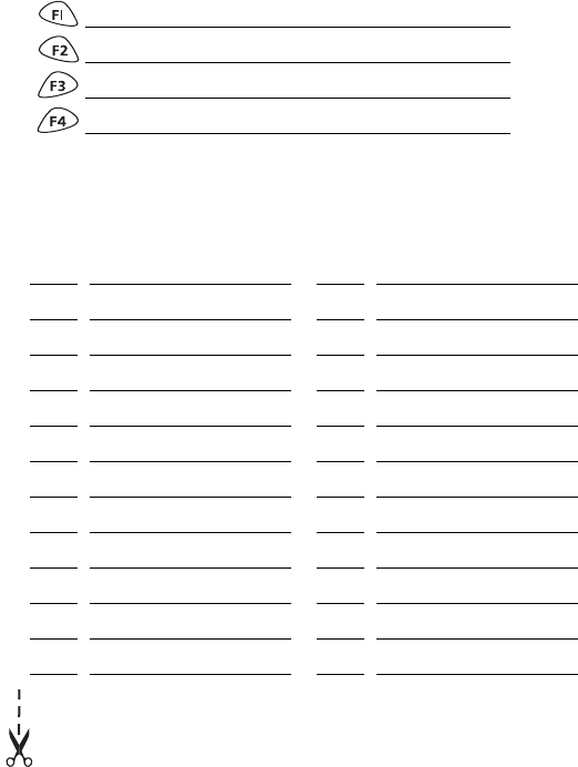
Your Radio’s Settings
Use the following table to list your radio’s programmed settings.
Channel List
Function Key Settings
ID Description ID Description
Radio Operation 5
Part 1: Radio Operation
About this Guide ...........................................................................1
Important Safety Information .......................................................................1
Updating this Guide ....................................................................................1
Safety Warnings ...........................................................................6
Warning: Safe Operation .......................................................................6
Warning: High Temperatures .................................................................6
Warning: FCC RF Exposure Limits ..........................................................6
Caution: Radio Protection ......................................................................7
Getting Started .............................................................................8
Radio Controls ............................................................................................8
Radio Indicators ........................................................................................10
LED Indicators .....................................................................................10
Audible Indicators ...............................................................................10
Basic Operation ...........................................................................11
Turning the Radio On and Off ....................................................................11
Adjusting the Volume ................................................................................11
Selecting a Channel ..................................................................................11
Making a Call ...........................................................................................11
Transmit Timer ....................................................................................12
Receiving a Call ........................................................................................12
What You Hear on a Channel ....................................................................12
Signalling Mute ...................................................................................12
Squelch ...............................................................................................13
Monitor ....................................................................................................13
Activating Monitor ..............................................................................13
Activating Squelch Override .................................................................13
Scanning ...................................................................................................14
Activating Scanning ............................................................................14
Nuisance Delete ..................................................................................14
Priority Scanning .................................................................................14
Troubleshooting .........................................................................15
Removing the Radio from the Vehicle ........................................................15
Notes ............................................................................................16
6Safety Warnings
Safety Warnings
Warning: Safe Operation
■Switch the radio off at petrol filling stations
or near flammable liquids or gases.
■Switch the radio off in the vicinity of explo-
sive devices and blasting zones.
■Using a handheld microphone or a radio
while driving a vehicle may violate the laws
and legislation that apply in your country or
state. Please check the vehicle regulations in your area.
Warning: High Temperatures
The bottom surface of the radio and the heatsink fins
can become hot during prolonged operation. Do not
touch these parts of the radio.
Warning: FCC RF Exposure Limits
This product generates RF (radio frequency) energy
during transmissions. This device must be restricted to
work-related use in an occupational/controlled expo-
sure environment.
The radio operator must have control of the exposure
conditions and duration of all persons exposed to the
antenna of this transmitter to satisfy FCC RF exposure
compliance. This device is not approved for general
population use.
■This device must only be used with authorized acces-
sories and antennas.
■The operator must ensure that the minimum safe dis-
tance of 0.9m (35 inches) between persons and the
antenna is maintained during transmissions.

Safety Warnings 7
■This minimum safe distance is based on the assump-
tion that there is a duty cycle of 50% transmit mode
to stand-by or receive modes. The radio is in transmit
mode when the PTT (press-to-talk) key on the micro-
phone is pressed and the control head red LED (light
emitting diode) glows.
Please refer to the following website for more informa-
tion on what RF energy is and how to control your
exposure to assure compliance with established RF
exposure limits.
Website: http://www.fcc.gov/oet/rfsafety/rf-faqs.html
Caution: Radio Protection
Always remove the fuses from the radio power cable
before charging the vehicle battery, connecting a second
battery or using power from another vehicle (e.g. when
“jump-starting” the vehicle).
8Getting Started
Getting Started
This section provides a brief description of your radio’s
basic operation. If you need further information, contact
your radio provider.
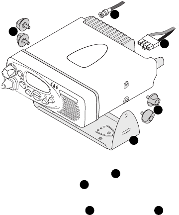
Radio
Controls
The radio controls are the PTT key, volume control, on/
off key, channel selection keys and function keys. Some
keys may have functions assigned to both short and long
key presses. A short key press is defined as less than one
second and a long key press is more than one second.
The radio controls and their functions are summarized in
the diagram and table on the following page.
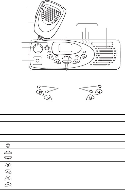
Getting Started 9
channel
selection keys
on/off key
volume
control
microphone
socket
PTT key
(press-to-talk)
red
LCD
display
speakergreen
amber
microphone radio status LEDs
function key
LEDs
function keys
3 and 4
function keys
1 and 2
Symbol Name Function
PTT press and hold to transmit and release
to listen
volume control rotate to change the speaker volume
on/off a long press turns the radio on or off
channel selection keys move up and down through the
channel list
function keys
1, 2, 3 and 4
function keys

10 Getting Started
Radio
Indicators
The LED indicators and the radio’s audible tones all
combine to give you information about the state of your
radio. The way these indicators behave is affected by the
way your radio is programmed.
The following sections describe the most common opera-
tion of the radio indicators.
LED Indicators
Audible Indicators
Your radio may be programmed so that whenever you
press a key, the radio beeps to indicate whether or not
your action is permitted.
A short, medium-pitched beep indicates that an action
or selection is permitted. A long, low-pitched beep indi-
cates that the action or selection is not permitted.
LED Meaning
red
(transmit)
glowing: your radio is transmitting
flashing: your transmit timer is about to
expire
green
(receive and
monitor)
glowing: there is activity on the current
channel, even though you may not be able
to hear it
flashing: you have received a call with valid
special signalling, or you have activated
monitor or squelch override
amber
(scanning)
glowing: your radio is scanning a group of
channels for activity
flashing: your radio has detected activity on
a channel, and has halted on this channel
function
key LEDs
the operation of these leds depends on the
type of function programmed for each
function key.
Basic Operation 11
Basic Operation
This section describes the basic operation of your radio,
including turning the radio on and off, adjusting volume,
selecting channels, making calls and receiving calls.
Turning the
Radio On
and Off
A long press of the on/off key turns the radio either
on or off. When the radio is first turned on, the red,
green and amber LEDs flash briefly and the radio gives
two short beeps.
Adjusting
the Volume
Rotate the volume control clockwise to increase the
speaker volume and counterclockwise to decrease the
volume. The volume control also changes the volume
level of the radio’s audible indicators.
Selecting a
Channel
Use the channel selection keys or to scroll
through the channel list until the channel you want
is displayed.
Making a
Call
1. Select the required channel or group using the chan-
nel selection keys or .
2. Check the green LED.
If the green LED is glowing, the channel is busy and
you cannot transmit.
3. Once the channel is clear (the green LED is off), lift
the microphone off the microphone clip.
4. Hold the microphone about 5cm (2 inches) from your
mouth and press the PTT key to transmit.
5. Speak clearly into the microphone and release the
PTT key when you have finished talking.
Note: You cannot change channels while
transmitting.

12 Basic Operation
Transmit Timer
Your radio may have a transmit timer that limits the
amount of time you can transmit continuously. When the
transmit timer is about to expire, the red LED flashes and
the radio gives three beeps. You must release the PTT
before you can transmit again.
Note: Your radio may be unable to transmit for
a short time after the transmit timer has
expired.
Receiving a
Call
When there is valid activity on your radio’s currently
selected channel or group, the radio then unmutes and
you can hear the call.
If the incoming call contains special signalling that
matches the signalling programmed for your radio, the
green LED flashes and your radio may give a ringing tone.
What You
Hear on a
Channel
Your radio may be programmed so that you hear all
conversations on a channel, or your user group may be
segregated from other user groups by using special
signalling. The special signalling is used to control the
muting and unmuting of your radio, so that your radio is
muted when other user groups are talking and unmuted
for members of your user group.
There are two muting controls that operate in your radio:
■signalling mute, and
■squelch.
Signalling Mute
The radio’s signalling mute only allows the radio to
unmute if the incoming call carries the tones specific to
your user group. Your user group may use tones that are
either audible, subaudible or both.

Basic Operation 13
Squelch
The radio’s squelch allows the radio to unmute only
when the strength of the incoming signal is above a
predetermined threshold. This means that only signals of
reasonable intelligibility are made audible.
Monitor
The monitor function is used to check that the channel is
clear before you make a call. While monitor is on, the
green LED flashes continually.
Activating Monitor
1. Press the monitor function key and monitor overrides
the signalling mute, allowing you to hear any traffic
on the channel.
Note: Your radio may be programmed to
activate monitor whenever the microphone
is off the microphone clip.
2. Press the monitor function key again to turn monitor
off, and the green LED no longer flashes.
Activating Squelch Override
1. Press and hold the monitor function key for longer
than one second to override both squelch and the
signalling mute.
This allows you to hear even faint and noisy signals.
2. Press the monitor function key again to return the
radio to a quiet state.
Note: Squelch cannot be overridden when
the radio is scanning.

14 Basic Operation
Scanning
The scan function is used to monitor a programmed
group of channels, looking for activity. When activity is
detected on one of the scan group channels, the radio
stops on that channel. The amber LED flashes and, if the
channel signalling is valid, the radio unmutes and you
can hear the call.
Scanning resumes when the channel is no longer busy or
the signalling is no longer valid.
Activating Scanning
1. Place the microphone on the microphone clip.
Note: Your radio may be programmed to
scan whenever the microphone is off the
microphone clip.
2. Press the function key assigned to scanning. The
amber LED glows to show that the radio is scanning.
3. Press the scanning function key again to cancel scan-
ning, and the amber LED no longer glows.
Nuisance Delete
If a member channel of the scan group is busy for a long
time and you do not wish to hear the conversation, you
can temporarily delete it from the scan group by using
the function key assigned to nuisance delete.
Alternatively, press and hold the scanning function key.
When the scan group is next selected, the deleted chan-
nel is again part of the scan group.
Priority Scanning
One or two priority scan channels may be set. These
channels are scanned more often than other channels
and are scanned periodically when a non-priority channel
is busy. Note that priority channels cannot be removed
from the scan group using the nuisance delete function.
Troubleshooting 15
Troubleshooting
If the red, green and amber LEDs on the control head do
not light up when the radio is turned on, it is likely that
no power is reaching the radio. Check the following:
■Is the power connector firmly plugged into the rear of
the radio?
■Are the in-line fuses in good condition?
■Is the power cable securely connected to the vehicle
battery or power supply?
If all appears to be in order, then contact your radio
provider for further assistance.
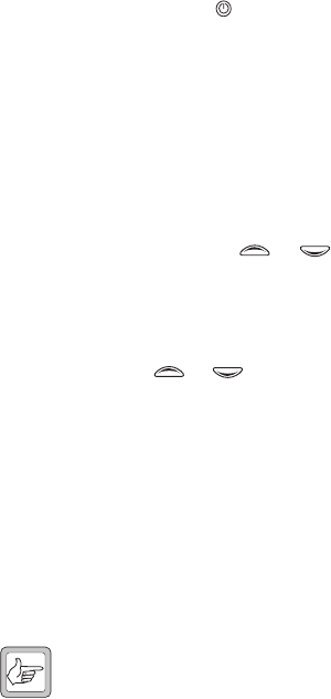
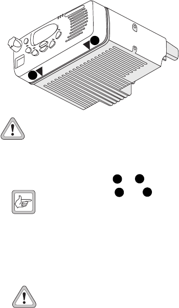
Removing
the Radio
from the
Vehicle
1. Switch off the radio.
2. Unscrew the four thumb screws that secure the
radio to the U-bracket .
3. Lift the radio clear of the U-bracket.
4. Disconnect the antenna and power cable
from the rear of the radio.
b
a
a
c
d
a
b
cd
16 Notes
Notes
Radio Installation Procedures 17
Part 2: Radio Installation Procedures
Installation Warnings .................................................................18
Warning: Safe Radio Mounting ............................................................18
Warning: Interference With Vehicular Electronics .................................18
Warning: Liquefied Petroleum Gas Powered Vehicles ...........................18
Caution: Non-Standard Radio Installations ...........................................19
Caution: Negative Ground Supply ........................................................19
Installation Planning ...................................................................20
MPT 1362 Code of Practice .......................................................................20
Checking Equipment .................................................................................20
Installation Tools .......................................................................................20
Microphone Clip Installation Tools .......................................................21
Mounting Position .....................................................................................21
Radio Installation ........................................................................22
Mounting the U-bracket ............................................................................22
Installing the Control Head on the Radio Body ...........................................22
Removing the Control Head .................................................................23
Installing the Microphone ..........................................................................23
Installing the Antenna ...............................................................................24
Warning: RF Exposure Hazard .............................................................24
Antenna Termination ..........................................................................24
Power Cable .............................................................................................25
Installing the Power Cable ...................................................................25
Installing the Radio in the U-bracket ..........................................................26
Microphone Clip (TM8115 Radios Only) ....................................................27
TM8105 Remote Connector ......................................................................27
Installation Checks ....................................................................................28
Other Installation Options .........................................................28

18 Installation Warnings
Installation Warnings
Warning: Safe Radio Mounting
■Mount the radio securely so that it will not break
loose in the event of a collision. An unsecured radio
is dangerous to the vehicle occupants.
■Mount the radio where it will not interfere with the
deployment of passenger air bags.
■Do not mount the radio vertically, with the control
head facing down. This will violate compliance with
the European Union standard EN 60950, Safety of
Information Technology Equipment.
Warning: Interference With Vehicular
Electronics
Some vehicular electronic devices may be prone to
malfunction, due to the lack of protection from RF
energy present when your radio is transmitting.
Examples of vehicular electronic devices that may be
affected by RF energy are:
■electronic fuel injection systems
■electronic anti-skid braking systems
■electronic cruise control systems.
If the vehicle contains such equipment, consult the vehi-
cle manufacturer or dealer in order to determine
whether these electronic circuits will perform normally
when the radio is transmitting.
Warning: Liquefied Petroleum Gas Powered
Vehicles
Radio installation in vehicles powered by LP (liquefied
petroleum) gas with the LP gas container in a sealed-off
space within the interior of the vehicle must conform to
the National Fire Protection Association Standard
Installation Warnings 19
NFPA 58. This standard states that the radio equipment
installation must meet the following requirements.
■The space containing the radio equipment shall be
isolated by a seal from the space containing the LP
gas container and its fitting.
■Outside filling connections shall be used for the LP
gas container and its fittings.
■The LP gas container space shall be vented to the
outside of the vehicle.
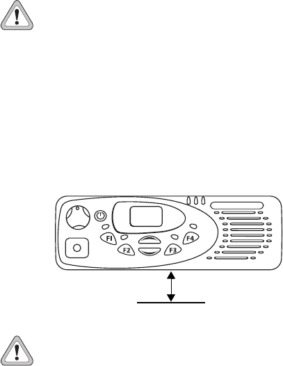
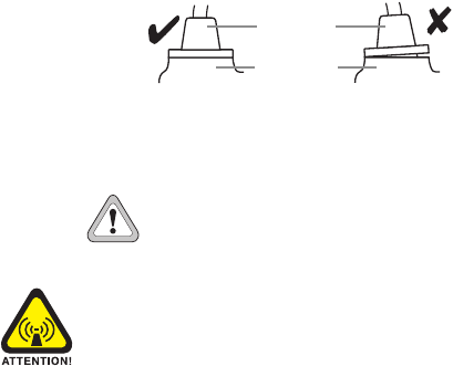
Caution: Non-Standard Radio Installations
The installation U-bracket described in this guide has
been designed so that there is enough airflow around
the radio to provide cooling.
If a non-standard installation method is used, care must
be taken that sufficient heat can be dissipated from the
radio heatsink fins and the bottom surface of the radio
chassis.
For this to be achieved, there must be a gap of more
than 10mm (0.4 inch) between the bottom surface of
the radio chassis and the mounting surface. This is illus-
trated in the following diagram.
Caution: Negative Ground Supply
TM8100 radios are designed to operate only in a nega-
tive ground system.
10mm
mounting surface
20 Installation Planning
Installation Planning
The procedures outlined in this and the following
sections are for installing a TM8105 or TM8115 radio in
a vehicle, using a standard U-bracket.
MPT 1362
Code of
Practice
TM8100 radios should be installed in accordance with
the MPT 1362 Code of Practice. This code of practice
covers the installation of mobile radio equipment in land
based vehicles and has been developed by the United
Kingdom Radiocommunications Agency.
The full text of the MPT 1362 Code of Practice can be
found at the Radiocommunications Agency website:
http://www.radio.gov.uk/
Checking
Equipment
Unpack the radio and check that you have the following
items:
■radio control head with connecting loom
■radio body
■microphone with microphone clip and screws
(TM8115 only)
■installation kit, consisting of:
— U-bracket with screws
— power cable with DC connector
— 10A fuses
— fuse holders
— BNC antenna plug.
Installation
Tools
■Portable drill
■8mm (0.3 inch) socket
■BNC crimp tool
■In-line RF power meter capable of measuring forward
and reflected power at the operating frequency of
the radio
Installation Planning 21
Microphone Clip Installation Tools
■Centre punch
■Drill bit
■Pozidriv screwdriver
■Hammer
Mounting
Position
Inspect the vehicle and determine the safest and most
convenient location for mounting the radio.
The installation must meet the following requirements:
■sufficient clearance behind the radio for the heatsink
and cables
■a large enough flat surface so that the mounting
bracket will not be distorted
■no danger of the radio interfering with air bag
deployment.
22 Radio Installation
Radio Installation
Mounting
the U-bracket
Screw the U-bracket in the chosen mounting position
using the self-tapping screws provided. At least four
screws must be installed.
Note: If the U-bracket is being mounted over
a curved surface, the U-bracket tabs can be
bent slightly.
Caution: Check that the tightening of the
screws does not distort the U-bracket.
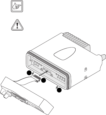
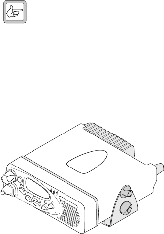
Installing the
Control Head
on the Radio
Body
The orientation of the U-bracket mounting determines
which way up the control head is mounted on the radio
body. The numbers in the diagram above refer to the
numbered steps below.
1. Plug the control head loom onto the control head
connector.
2. Insert the bottom edge of the control head onto the
two clips in the front of the radio chassis, then snap
into place.
2
1
2
Radio Installation 23
Removing the Control Head
Caution: During this procedure, take care that
the chassis seal is not damaged. Damage to this
seal reduces environmental protection.
1. On the underside of the radio, insert a flat-bladed
screwdriver between the control head and the radio
chassis seal, in either position or .
Note: Insertion points and are indi-
cated on the radio chassis by a dot-dash-dot
pattern (•–•).
2. Use the screwdriver to lift the control head off the
chassis clip, then repeat in the other position.
The control head can now be removed from the
radio body.
Installing the
Microphone
Caution: The microphone grommet must be
installed whenever the microphone is
plugged into the microphone socket. When
installed, the grommet has two functions:
■to prevent damage to the microphone socket when
there is movement of the microphone cord, and
■to ensure that the control head is sealed against
water, dust and other environmental hazards.
2
1
12
12
24 Radio Installation
1. Plug the microphone into the microphone socket on
the control head.
2. Slide the microphone grommet along the microphone
cord and push two adjacent corners of the grommet
into the microphone socket cavity.
3. Squeeze the grommet and push the remaining
corners into position.
4. Check that the grommet is seated correctly in the cavity.
Installing the
Antenna
Install the external antenna according to the supplier’s
instructions. Good quality 50 ohm coaxial cable must be
used, such as RG58 or UR76.
Caution: The cable should be routed in a
manner that minimizes coupling into the
electronic control systems of the vehicle.
Warning: RF Exposure Hazard
To comply with FCC RF exposure limits, this product
must be installed using an externally mounted antenna
with either a 2.15dBi or 5.15dBi gain.
This antenna must not be mounted at a location such
that any person or persons can come closer than 0.9m
(35 inches) to the antenna.
Antenna Termination
1. Run the free end of the coaxial cable to the radio’s
mounting position and cut it to length, allowing 20 -
30cm (8 - 12 inches) excess.
2. Terminate the free end of the cable with the BNC
plug supplied.
microphone
grommet
control head

Radio Installation 25
Power Cable
Caution: This radio is designed to operate from
a nominal 12V negative ground supply and may
draw up to 8A of current. The radio will tolerate
a supply voltage range of 10.8V to 16.0V at the radio.
In vehicles with a supply voltage greater than 16.0V,
such as many trucks, it is essential to provide a suitably
rated DC to DC converter. This will isolate the radio from
excessive battery voltage and provide the correct DC
operating conditions.
Installing the Power Cable
Caution: Disconnecting the vehicle’s battery
may cause problems with some electronic
equipment, such as vehicle alarms, engine
management systems and in-car entertainment systems.
Check that the vehicle owner has the necessary informa-
tion to make all electronic equipment function correctly
after battery reconnection.
1. Disconnect the vehicle’s battery, unless specifically
prohibited from doing so by the customer, vehicle
manufacturer, agent or supplier.
If the battery is not disconnected, exercise extreme
caution throughout the installation and install the
fuses only when the installation is ready to be
checked (see “Installation Checks” on page 28).
2. Determine where the power cable will be routed.
Caution: The power cable should be
protected from engine heat, sharp edges
and from being pinched or crushed.
26 Radio Installation
3. Cut the negative and the positive wires where the in-
line fuse holders will be placed (as close to the
battery as possible).
Note: Do not install the fuses until the
installation is ready to be checked.
4. Insert each end of the negative wire into one of the
in-line fuse holders and crimp them to force the
metal contacts onto the wires.
5. Connect the negative wire to the battery ground.
6. Repeat step 4 for the positive wire and connect it to
the positive terminal of the battery.
Installing the
Radio in the
U-bracket
1. Connect the antenna and power cables to the rear of
the radio.
2. Position the radio in the U-bracket so that the
holes in the U-bracket line up with the holes in the
radio chassis.
3. Screw the radio into position using the four thumb
screws but without fully tightening the screws.
4. Position the radio in the U-bracket for best viewing
angle, then tighten the thumb screws.
Radio Installation 27
Microphone
Clip (TM8115
Radios Only)
Install the microphone clip in the most convenient loca-
tion for the radio user. It must be within easy reach of
the user, but in such a position that the microphone PTT
key cannot be inadvertently activated or jammed on.
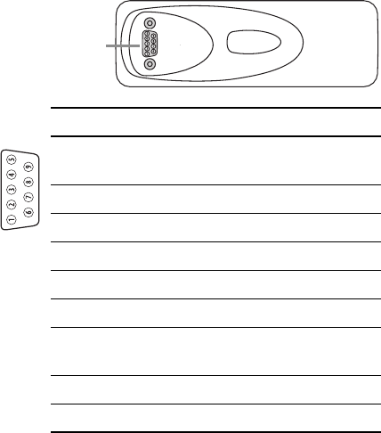
TM8105
Remote
Connector
The TM8105 has a 9-way D-range socket on the control
head, for remote connection. The pin allocations of the
remote connector are shown in the following diagram
and table.
remote
connector
Pin Signal Description
1RX_AUD receive audio output (after volume
control)
2 TXD asynchronous serial port: transmit data
3MIC_AUD microphone audio input
4RXD asynchronous serial port: receive data
5ON_OFF hardware power on/software power off
6+13V8_BATT unswitched 13.8V power supply
7PTT PTT input from microphone, with
hookswitch signal
8AGND analogue ground
9DGND digital ground

28 Other Installation Options
Installation
Checks
1. Insert the fuses into the power leads.
2. TM8115 radios only.
Switch on the radio to confirm that it is operational
(see “Turning the Radio On and Off” on page 11).
Caution: Do not transmit yet.
3. Connect an in-line power meter between the radio
and the antenna and measure the forward and
reflected power levels.
Less than 4% of the forward power should be
reflected. If this is not achieved, check the installa-
tion, including the antenna length.
4. TM8115 radios only.
Once the reflected power levels are within tolerance,
make a call to another party on the radio (see
“Selecting a Channel” and “Making a Call”, on
page 11).
Other Installation Options
A wide range of other radio installation options are
available, such as desktop installation, DIN mounting
and locking bracket installation.
Contact your radio provider for further information.