Exhibit D Users Manual per 2 1033 c3

TM9100 mobiles (40W/50W)
Installation Guide
Draft 0.03
October 2004

2TM9100 (40W/50W) Installation Guide
© Tait Electronics Ltd October 2004
Contact Information
Tait Radio Communications http://www.taitworld.com
Corporate Head Office
New Zealand
Tait Electronics Ltd
P.O. Box 1645
Christchurch
New Zealand
E-mail: info@taitworld.com
Website: http://www.taitworld.com
Technical Support:
E-mail: support@taitworld.com
Website: http://support.taitworld.com
Tait North America
Regional Head Office -
United States of America
Tait North America Inc
E-mail: usa@taitworld.com
Canada
Tait North America Inc
E-mail: canada@taitworld.com
Tait Latin America
Tait Latin America
E-mail: latinamerica@taitworld.com
Tait Europe
Regional Head Office - United Kingdom
Tait Mobile Radio Ltd
E-mail: teusales@tait.co.uk
Tait North Asia
Regional Head Office - Hong Kong
Tait Mobile Radio (Hong Kong) Ltd
E-mail: hongkong@taitworld.com
Beijing
Tait Mobile Radio (Hong Kong) Ltd
E-mail: beijing@taitworld.com
Tait South Asia
Regional Head Office - Singapore
Tait Electronics (Far East) Pte Ltd
E-mail: singapore@taitworld.com
Thailand
Tait Mobile Radio Ltd
E-mail: thailand@taitworld.com
Tait Oceania
New Zealand
Tait Communications Ltd
E-mail: headoffice@tcl.tait.co.nz
Australia
Tait Electronics (Aust) Pty Ltd
E-mail: australia@taitworld.com
Note: For the addresses and phone numbers of the
above regional offices refer to the TaitWorld website.

TM9100 (40W/50W) Installation Guide 3
© Tait Electronics Ltd October 2004
Tait General Software Licence Agreement
This legal document is an Agreement between you
(the “Licensee”) and Tait Electronics Limited (“Tait”).
By using any of the Software or Firmware items prior-
installed in the related Tait product, included on this CD
or downloaded from the Tait website, (hereinafter
referred to as “the Software or Firmware”) you agree to
be bound by the terms of this Agreement. If you do not
agree to the terms of this Agreement, do not install and
use any of the Software or Firmware. If you install and
use any of the Software or Firmware that will be deemed
to be acceptance of the terms of this licence agreement.
The terms of this agreement shall apply subject only to
any express written terms of agreement to the contrary
between Tait and the Licensee.
Licence
TAIT GRANTS TO YOU AS LICENSEE THE NON-EXCLUSIVE
RIGHT TO USE THE SOFTWARE OR FIRMWARE ON A SINGLE
MACHINE PROVIDED YOU MAY ONLY:
1. COPY THE SOFTWARE OR FIRMWARE INTO ANY
MACHINE READABLE OR PRINTED FORM FOR BACKUP
PURPOSES IN SUPPORT OF YOUR USE OF THE PROGRAM ON
THE SINGLE MACHINE (CERTAIN PROGRAMS, HOWEVER,
MAY INCLUDE MECHANISMS TO LIMIT OR INHIBIT COPYING,
THEY ARE MARKED “COPY PROTECTED”), PROVIDED THE
COPYRIGHT NOTICE MUST BE REPRODUCED AND
INCLUDED ON ANY SUCH COPY OF THE SOFTWARE OR
FIRMWARE;
AND / OR
2. MERGE IT INTO ANOTHER PROGRAM FOR YOUR USE ON
THE SINGLE MACHINE (ANY PORTION OF ANY SOFTWARE
OR FIRMWARE MERGED INTO ANOTHER PROGRAM WILL
CONTINUE TO BE SUBJECT TO THE TERMS AND
CONDITIONS OF THIS AGREEMENT).
THE LICENSEE MAY NOT DUPLICATE, MODIFY, REVERSE
COMPILE OR REVERSE ASSEMBLE ANY SOFTWARE OR
FIRMWARE IN WHOLE OR PART.
Title to Software
THIS AGREEMENT DOES NOT CONSTITUTE A CONTRACT OF
SALE IN RELATION TO THE SOFTWARE OR FIRMWARE
SUPPLIED TO THE LICENSEE. NOT WITHSTANDING THE
LICENSEE MAY OWN THE MAGNETIC OR OTHER PHYSICAL
MEDIA ON WHICH THE SOFTWARE OR FIRMWARE WAS
ORIGINALLY SUPPLIED, OR HAS SUBSEQUENTLY BEEN
RECORDED OR FIXED, IT IS A FUNDAMENTAL TERM OF THIS
AGREEMENT THAT AT ALL TIMES TITLE AND OWNERSHIP OF
THE SOFTWARE OR FIRMWARE, WHETHER ON THE
ORIGINAL MEDIA OR OTHERWISE, SHALL REMAIN VESTED IN
TAIT OR THIRD PARTIES WHO HAVE GRANTED LICENCES TO
TAIT.
Term and Termination
THIS LICENCE SHALL BE EFFECTIVE UNTIL TERMINATED IN
ACCORDANCE WITH THE PROVISIONS OF THIS AGREEMENT.
THE LICENSEE MAY TERMINATE THIS LICENCE AT ANY TIME
BY DESTROYING ALL COPIES OF THE SOFTWARE OR
FIRMWARE AND ASSOCIATED WRITTEN MATERIALS. THIS
LICENCE WILL BE TERMINATED AUTOMATICALLY AND
WITHOUT NOTICE FROM TAIT IN THE EVENT THAT THE
LICENSEE FAILS TO COMPLY WITH ANY TERM OR
CONDITION OF THIS AGREEMENT. THE LICENSEE AGREES
TO DESTROY ALL COPIES OF THE SOFTWARE OR FIRMWARE
AND ASSOCIATED WRITTEN MATERIALS IN THE EVENT OF
SUCH TERMINATION.
Limited Warranty
THE SOFTWARE OR FIRMWARE IS SUPPLIED BY TAIT AND
ACCEPTED BY THE LICENSEE “AS IS” WITHOUT WARRANTY
OF ANY KIND EITHER EXPRESSED OR IMPLIED, INCLUDING
BUT NOT BEING LIMITED TO ANY IMPLIED WARRANTIES AS
TO MERCHANTABILITY OR FITNESS FOR ANY PARTICULAR
PURPOSE. THE LICENSEE ACKNOWLEDGES THAT THE
SOFTWARE OR FIRMWARE IS USED BY IT IN BUSINESS AND
ACCORDINGLY TO THE MAXIMUM EXTENT PERMITTED BY
LAW NO TERMS OR WARRANTIES WHICH ARE IMPLIED BY
LEGISLATION SHALL APPLY TO THIS AGREEMENT. TAIT DOES
NOT WARRANT THAT THE FUNCTIONS CONTAINED IN THE
SOFTWARE OR FIRMWARE WILL MEET THE LICENSEE’S
REQUIREMENTS OR THAT THE OPERATION OF THE
SOFTWARE OR FIRMWARE WILL BE UNINTERRUPTED OR
ERROR FREE.
Exclusion of Liability
TAIT’S ENTIRE LIABILITY AND THE LICENSEE’S EXCLUSIVE
REMEDY SHALL BE THE FOLLOWING:
1. IN NO CIRCUMSTANCES SHALL TAIT BE UNDER ANY
LIABILITY TO THE LICENSEE, OR ANY OTHER PERSON
WHATSOEVER, FOR ANY DIRECT OR CONSEQUENTIAL
DAMAGE ARISING OUT OF OR IN CONNECTION WITH ANY
USE OR INABILITY OF USING THE SOFTWARE OR FIRMWARE.
2. TAIT WARRANTS THE OPERATION OF THE SOFTWARE OR
FIRMWARE ONLY WITH THE OPERATING SYSTEM FOR
WHICH IT WAS DESIGNED. USE OF THE SOFTWARE OR
FIRMWARE WITH AN OPERATING SYSTEM OTHER THAN
THAT FOR WHICH IT WAS DESIGNED MAY NOT BE
SUPPORTED BY TAIT, UNLESS OTHERWISE EXPRESSLY
AGREED BY TAIT.
General
THE LICENSEE CONFIRMS THAT IT SHALL COMPLY WITH
THE PROVISIONS OF LAW IN RELATION TO THE SOFTWARE
OR FIRMWARE.
4TM9100 (40W/50W) Installation Guide
© Tait Electronics Ltd October 2004
Law and Jurisdiction
THIS AGREEMENT SHALL BE SUBJECT TO AND CONSTRUED
IN ACCORDANCE WITH NEW ZEALAND LAW AND DISPUTES
BETWEEN THE PARTIES CONCERNING THE PROVISIONS
HEREOF SHALL BE DETERMINED BY THE NEW ZEALAND
COURTS OF LAW. PROVIDED HOWEVER TAIT MAY AT ITS
ELECTION BRING PROCEEDINGS FOR BREACH OF THE
TERMS HEREOF OR FOR THE ENFORCEMENT OF ANY
JUDGEMENT IN RELATION TO A BREACH OF THE TERMS
HEREOF IN ANY JURISDICTION TAIT CONSIDERS FIT FOR
THE PURPOSE OF ENSURING COMPLIANCE WITH THE
TERMS HEREOF OR OBTAINING RELIEF FOR BREACH OF THE
TERMS HEREOF.
No Dealings
THE LICENSEE MAY NOT SUBLICENSE, ASSIGN OR TRANSFER
THE LICENCE OR THE PROGRAM EXCEPT AS EXPRESSLY
PROVIDED IN THIS AGREEMENT. ANY ATTEMPT OTHERWISE
TO SUBLICENSE, ASSIGN OR TRANSFER ANY OF THE RIGHTS,
DUTIES OR OBLIGATIONS HEREUNDER IS VOID.
No Other Terms
THE LICENSEE ACKNOWLEDGES THAT IT HAS READ THIS
AGREEMENT, UNDERSTANDS IT AND AGREES TO BE BOUND
BY ITS TERMS AND CONDITIONS. THE LICENSEE FURTHER
AGREES THAT SUBJECT ONLY TO ANY EXPRESS WRITTEN
TERMS OF AGREEMENT TO THE CONTRARY BETWEEN TAIT
AND THE LICENSEE THIS IS THE COMPLETE AND EXCLUSIVE
STATEMENT OF THE AGREEMENT BETWEEN IT AND TAIT IN
RELATION TO THE SOFTWARE OR FIRMWARE WHICH
SUPERSEDES ANY PROPOSAL OR PRIOR AGREEMENT,
ORAL OR WRITTEN AND ANY OTHER COMMUNICATIONS
BETWEEN THE LICENSEE AND TAIT RELATING TO THE
SOFTWARE OR FIRMWARE.

TM9100 (40W/50W) Installation Guide 5
© Tait Electronics Ltd October 2004
Contents
Preface. . . . . . . . . . . . . . . . . . . . . . . . . . . . . . . . . . . . . . . . . . . . . . . . . . . . . . . . . . . . .6
Scope of Manual . . . . . . . . . . . . . . . . . . . . . . . . . . . . . . . . . . . . . . . . . . . . . . . . . . . . . . . . . . . . . 6
Enquiries and Comments . . . . . . . . . . . . . . . . . . . . . . . . . . . . . . . . . . . . . . . . . . . . . . . . . . . . . . . 6
Updates of Manual and Equipment. . . . . . . . . . . . . . . . . . . . . . . . . . . . . . . . . . . . . . . . . . . . . . . . 6
Copyright . . . . . . . . . . . . . . . . . . . . . . . . . . . . . . . . . . . . . . . . . . . . . . . . . . . . . . . . . . . . . . . . . . 6
Disclaimer . . . . . . . . . . . . . . . . . . . . . . . . . . . . . . . . . . . . . . . . . . . . . . . . . . . . . . . . . . . . . . . . . . 6
Document Conventions. . . . . . . . . . . . . . . . . . . . . . . . . . . . . . . . . . . . . . . . . . . . . . . . . . . . . . . . 7
Safety Warnings. . . . . . . . . . . . . . . . . . . . . . . . . . . . . . . . . . . . . . . . . . . . . . . . . . . . . . . 8
1 Preparing the Installation . . . . . . . . . . . . . . . . . . . . . . . . . . . . . . . . . . . . . . . . . . . . 11
1.1 Regulations . . . . . . . . . . . . . . . . . . . . . . . . . . . . . . . . . . . . . . . . . . . . . . . . . . . . . . . . . . . .11
1.2 Installation Tools . . . . . . . . . . . . . . . . . . . . . . . . . . . . . . . . . . . . . . . . . . . . . . . . . . . . . . . .11
1.3 Choosing an Installation Configuration . . . . . . . . . . . . . . . . . . . . . . . . . . . . . . . . . . . . . . . .12
2 Installing the Radio . . . . . . . . . . . . . . . . . . . . . . . . . . . . . . . . . . . . . . . . . . . . . . . . 13
2.1 Mounting and Removing the Control Head . . . . . . . . . . . . . . . . . . . . . . . . . . . . . . . . . . . .13
2.2 Selecting the Mounting Position . . . . . . . . . . . . . . . . . . . . . . . . . . . . . . . . . . . . . . . . . . . . .15
2.3 Mounting the Radio. . . . . . . . . . . . . . . . . . . . . . . . . . . . . . . . . . . . . . . . . . . . . . . . . . . . . .16
2.4 Installing the Microphone. . . . . . . . . . . . . . . . . . . . . . . . . . . . . . . . . . . . . . . . . . . . . . . . . .17
2.5 Installing the Antenna. . . . . . . . . . . . . . . . . . . . . . . . . . . . . . . . . . . . . . . . . . . . . . . . . . . . .18
2.6 Connecting the Power Cable . . . . . . . . . . . . . . . . . . . . . . . . . . . . . . . . . . . . . . . . . . . . . . .19
2.7 Connecting a Remote Speaker . . . . . . . . . . . . . . . . . . . . . . . . . . . . . . . . . . . . . . . . . . . . . .21
2.8 Connecting to the Auxiliary Connector. . . . . . . . . . . . . . . . . . . . . . . . . . . . . . . . . . . . . . . .21
2.9 Checking the Installation . . . . . . . . . . . . . . . . . . . . . . . . . . . . . . . . . . . . . . . . . . . . . . . . . .24

6TM9100 (40W/50W) Installation Guide
© Tait Electronics Ltd October 2004
Preface
Scope of Manual
This manual describes the installation of the TM9100 mobile radios,
microphones, antennas, emergency switches, and external alert devices.
The installation of accessories is described in the installation instructions
provided with the accessories and the relevant section of the service manual.
Enquiries and Comments
If you have any enquiries regarding this manual, or any comments,
suggestions and notifications of errors, please contact Technical Support,
Tait Electronics Ltd, Christchurch, New Zealand (refer to “Contact
Information” on page 2).
Updates of Manual and Equipment
In the interests of improving the performance, reliability or servicing of the
equipment, Tait Electronics Ltd reserves the right to update the equipment
or this manual or both without prior notice.
Copyright
All information contained in this manual is the property of Tait Electronics
Ltd. All rights are reserved. This manual may not, in whole or in part, be
copied, photocopied, reproduced, translated, stored, or reduced to any
electronic medium or machine-readable form, without prior written
permission from Tait Electronics Limited.
All trade names referenced are the service mark, trademark or registered
trademark of the respective manufacturers.
Disclaimer
There are no warranties extended or granted by this manual. Tait Electronics
Ltd accepts no responsibility for damage arising from use of the information
contained in the manual or of the equipment and software it describes.
It is the responsibility of the user to ensure that use of such information,
equipment and software complies with the laws, rules and regulations of the
applicable jurisdictions.

TM9100 (40W/50W) Installation Guide 7
© Tait Electronics Ltd October 2004
Document Conventions
Within this manual, four types of alerts are given to the reader: Warning,
Caution, Important and Note. The following paragraphs illustrate each type
of alert and its associated symbol.
Warning!! This alert is used when there is a potential risk of death
or serious injury.
Caution This alert is used when there is the risk of minor or moderate
injury to people.
Important This alert is used to warn about the risk of equipment
damage or malfunction.
Note This alert is used to highlight information that is required to ensure
procedures are performed correctly.
8TM9100 (40W/50W) Installation Guide
© Tait Electronics Ltd October 2004
Safety Warnings
Introduction This chapter contains important information on the safe
installation of the radio. You must read this information before
starting the installation!
You must read and observe the safety information on radio
operation provided in the product safety and compliance
information and the user’s guide!
Warning!! RF exposure hazard
To comply with FCC RF exposure limits:
■VHF radios must be installed using an antenna mounted centrally on the
vehicle roof, with a gain of 2.15dBi or 5.15dBi.
■UHF radios must be installed using an antenna mounted either centrally
on the roof with a gain of 2.15dBi or 5.65dBi, or centrally mounted on
the trunk with a gain of 5.65dBi.
This antenna must not be mounted at a location such that any person or
persons can come closer than 35 inches (0.9m) to the antenna.
Warning!! Safe radio mounting
■Mount the radio securely so that it will not break loose in the event of a
collision. An unsecured radio is dangerous to the vehicle occupants.
■Mount the radio and the microphone where they will not interfere with
the vehicle operator controls.
■Mount the radio and the microphone where they will not interfere with
the vehicle operator’s view.
■Mount the radio and the microphone where they will not interfere with
air bag deployment.
Warning!! Interference with vehicular electronics
Some vehicular electronic devices may be prone to malfunction, due to the
lack of protection from RF energy present when your radio is transmitting.
Examples of vehicular electronic devices that may be affected by RF energy
are:
■electronic fuel injection systems
■electronic anti-skid braking systems
■electronic cruise control systems.
If the vehicle contains such equipment, consult the vehicle manufacturer or
dealer in order to determine whether these electronic circuits will perform
normally when the radio is transmitting.
TM9100 (40W/50W) Installation Guide 9
© Tait Electronics Ltd October 2004
Warning!! Vehicles powered by liquefied petroleum gas
Radio installation in vehicles powered by LP (liquefied petroleum) gas with
the LP gas container in a sealed-off space within the interior of the vehicle
must conform to the National Fire Protection Association Standard
NFPA 58. This standard states that the radio equipment installation must
meet the following requirements.
■The space containing the radio equipment shall be isolated by a seal from
the space containing the LP gas container and its fitting.
■Outside filling connections shall be used for the LP gas container and its
fittings.
■The LP gas container space shall be vented to the outside of the vehicle.
Caution Negative earth supply
The radios are designed to operate only in a negative earth system.
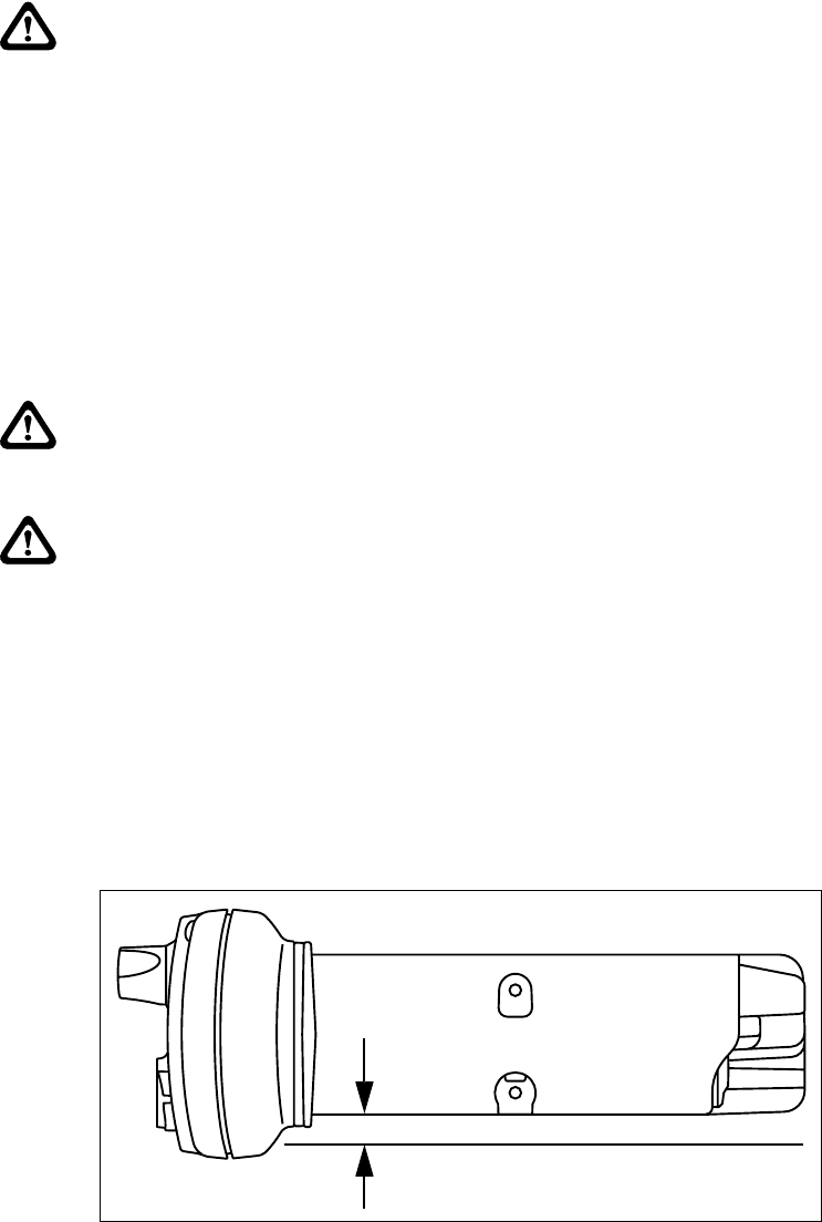
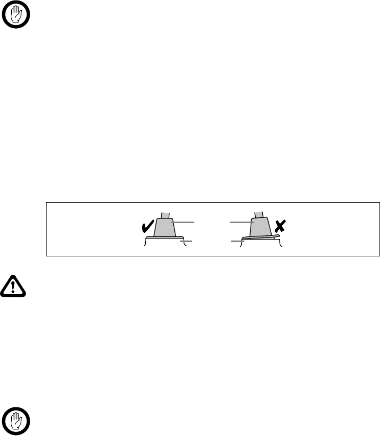
Caution Insufficient heat dissipation with non-standard radio
installations
An unobstructed flow of air is required over the underside and rear of the
radio to ensure adequate cooling. The installation U-bracket described in
this guide has been designed to ensure such an airflow.
If a non-standard installation method is used, ensure that sufficient heat can
be dissipated from the cooling fins at the rear of the radio as well as from the
ridged underside of the radio. To achieve this, there must be a gap of more
than 3/8 inch (10mm) between the underside of the radio body and the
mounting.
3/8 inch (10 mm)
10 TM9100 (40W/50W) Installation Guide
© Tait Electronics Ltd October 2004

TM9100 (40W/50W) Installation Guide 11
© Tait Electronics Ltd October 2004
1 Preparing the Installation
Overview This chapter provides you with the information required to:
■know the regulations regarding the installation of mobile radios
■provide the tools required for installation
■choose the appropriate installation configuration
1.1 Regulations
MPT 1362 Code of Practice Tait Electronics recommend that mobile radios be installed in accordance
with the MPT 1362 Code of Practice.
Vehicle Manufacturer’s Installation
Instructions Follow your vehicle manufacturer’s instructions on the installation of mobile
radios. For more information refer to the vehicle manufacturer’s website or
contact the vehicle manufacturer’s dealer.
1.2 Installation Tools
The following tools are required for the installation of the radio:
■drill and drill bits
■Pozidriv screwdriver
■5/16 inch (8mm) socket (or Pozidriv screwdriver)
■RF connector crimp tool
■fuse crimp tool
■in-line RF power meter capable of measuring forward and reflected
power at the operating frequency of the radio

12 TM9100 (40W/50W) Installation Guide
© Tait Electronics Ltd October 2004
1.3 Choosing an Installation Configuration
Introduction The radio allows for different installation configurations for vehicles with
respect to ignition signal and standby current. For special configurations for
desktop and remote site installations, refer to the service manual.
The installation configurations described below are based on the following
hardware link configuration:
■hardware link 1 (+13.8V battery power sense): fitted
■hardware link 2 (ignition sense): fitted
For more information on the hardware links, refer to the service manual.
Direct Connection to the Power Source The radio’s power cable must always be connected directly to the power
source (battery).
Important Although it is possible to connect the radio in line with the
vehicle ignition, this installation method is not
recommended, as it may draw too much current, resulting
in damage to the vehicle wiring and steering column or
ignition switch. This may also cause the supply voltage of
the radio to drop below the specified level.
The radio can always be turned on and off using the on/off button,
independent of the ignition signal.
Installation without Ignition Signal Connect the power cable directly to the power source as described in
“Connecting the Power Cable” on page 19.
Note If hardware link 1 is fitted and the ignition signal is not used, the
standby current is 28mA. To reduce the standby current to 1mA:
– remove hardware link 1, or
– connect pin 4 (AUX_GPIO3) to pin 15 (GND) of the auxiliary
connector, and program the AUX_GPIO3 line as described below.
Installation with Ignition Signal Connect the power cable directly to the power source as described in
“Connecting the Power Cable” on page 19.
Connect pin 4 (AUX_GPIO3) of the auxiliary connector to the ignition
signal as described in “Connecting to the Auxiliary Connector” on page 21.
Note The AUX_GPI3 line must be programmed to ‘Power Sense
(Ignition)’ and active to ‘High’. For more information, refer to the
online help of the application software.
TM9100 (40W/50W) Installation Guide 13
© Tait Electronics Ltd October 2004
2 Installing the Radio
Introduction This chapter provides the information required to:
■mount and remove the control head
■select a safe and convenient mounting position
■mount the radio
■install the microphone and microphone clip
■install the antenna
■connect the power cable
■connect a remote speaker
■connect to the auxiliary connector
■carry out installation checks
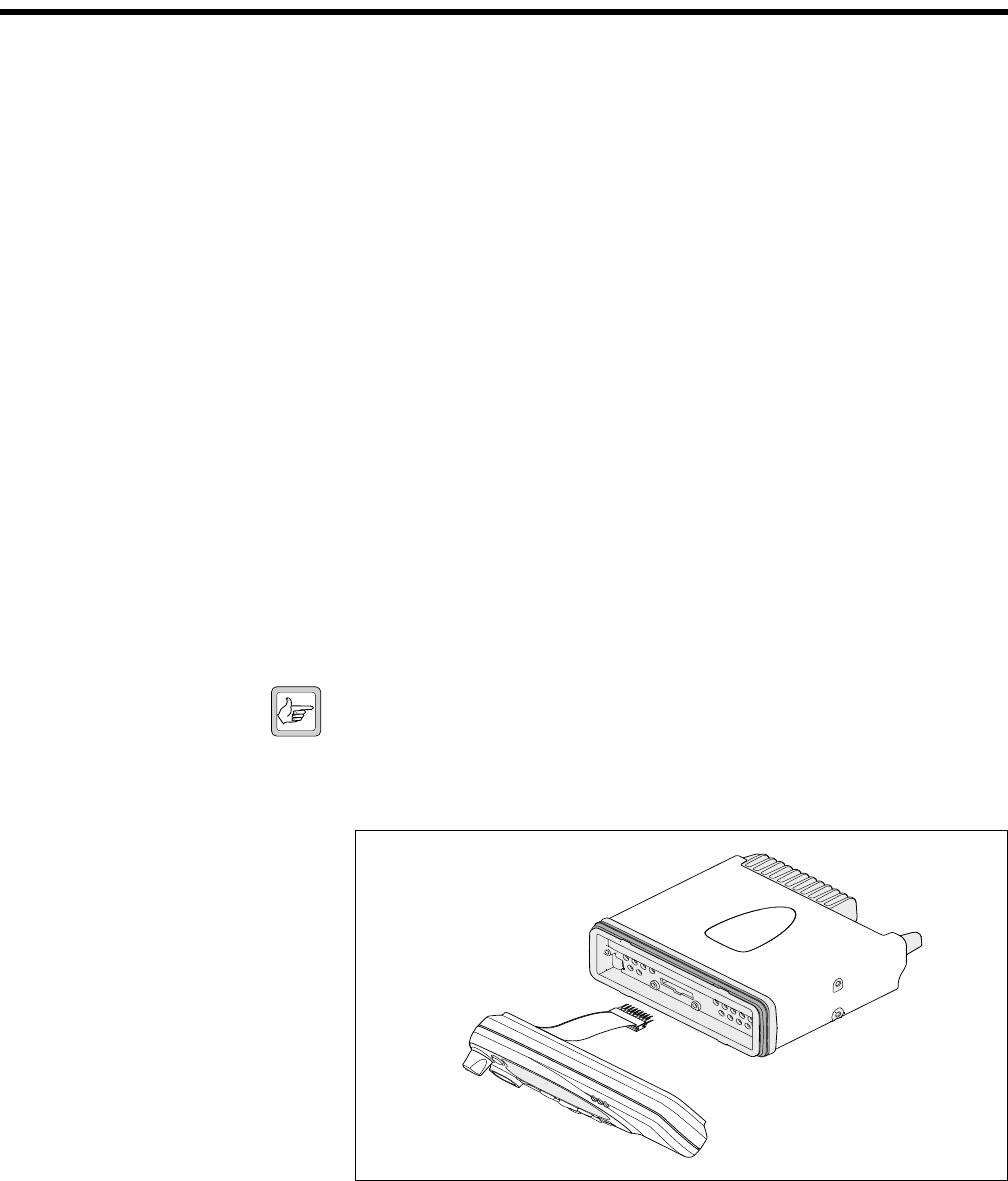
2.1 Mounting and Removing the Control Head
Mounting the Control Head The radio body and the control head and its connection loom are delivered
separately. Before installing the radio, the control head should be mounted
on the radio body.
The orientation of the radio body determines which way up the control
head is mounted on the radio body.
Note It may be required to mount the radio upside down in order to
maintain a gap of more than 3/8 inch (10mm) for air circulation
between the underside of the radio body and the mounting.
1. Plug the control-head loom onto the control-head connector.
2. Insert the bottom edge of the control head onto the two clips in the
front of the radio body, then snap into place.
Figure 2.1 Mounting the control head
14 TM9100 (40W/50W) Installation Guide
© Tait Electronics Ltd October 2004
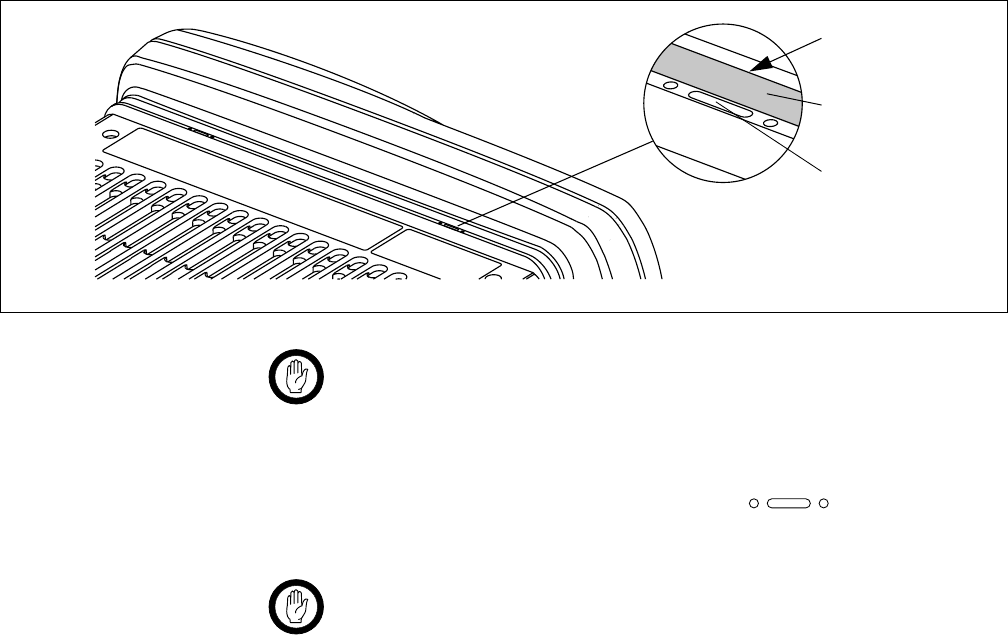
Removing the Control Head Important During this procedure, take care that the control-head seal
is not damaged. Damage to this seal reduces environmental
protection.
1. On the underside of the radio, two lever points are indicated on the
radio body by a dot-dash-dot pattern ( ). The lever point is
between the control-head seal and the control head.
Important When inserting the screwdriver, take care not to damage
the control-head seal.
2. At either of the lever points, insert a 3/16 inch (5mm) flat-bladed
screwdriver between the control head and the control-head seal.
3. Use the screwdriver to lift the control head off the clip, then repeat in
the other position. The control head can now be removed.
Figure 2.2 Disconnecting the control head from the radio body
lever point
indication of
lever point
control-head
seal

TM9100 (40W/50W) Installation Guide 15
© Tait Electronics Ltd October 2004
2.2 Selecting the Mounting Position
Requirements for Safe and Convenient
Installation Make sure the mounting position complies with the requirements of the
following safety warnings:
Warning!! Safe radio mounting
■Mount the radio securely so that it will not break loose in the event of a
collision. An unsecured radio is dangerous to the vehicle occupants.
■Mount the radio and the microphone where they will not interfere with
the vehicle operator controls.
■Mount the radio and the microphone where they will not interfere with
the vehicle operator’s view.
■Mount the radio and the microphone where they will not interfere with
air bag deployment.
Gap between Radio Body
and Mounting Surface Note It may be required to mount the radio upside down in order to
maintain a gap of more than 3/8 inch (10mm) between the bottom
surface of the radio body and the mounting surface.
Inspect the vehicle and determine the safest and most convenient position
for mounting the radio. Make sure that there sufficient clearance behind the
radio for the heatsink and cables.
IP54 Protection
Class Considerations Important The radio is specified to fulfil the requirements of the IP54
protection class. However, the following must be consid-
ered:
The radio must not be mounted in areas, where an accumulation of water
or other liquids can result in the temporary submersion of the radio (e.g.
when using a high-pressure cleaning device).
The IP54 protection class does not apply when:
■the control head is removed from the radio body
■the bungs are removed from the auxiliary connector or the aperture for
the external options connector (fitting an auxiliary connector or external
options connector will not restore the IP54 protection class)
■the microphone grommet is not installed

16 TM9100 (40W/50W) Installation Guide
© Tait Electronics Ltd October 2004
2.3 Mounting the Radio
Introduction The U-bracket included in the installation kit can be used to install the radio
on the dashboard or on any sufficiently flat surface (e.g. cabin floor or
trunk). The U-bracket can be mounted using the self-drilling screws and
washers provided, or nuts and bolts (not included).
Caution Although an industrial-strength recloseable fastening system
can be used to support the installation, Tait does not
recommend this as a mounting option for safety reasons.
Installation Important When mounting the radio on a surface, check whether the
mounting screws will screw into material providing suffi-
cient strength. Reinforce the mounting surface, if required.
1. If the U-bracket is being mounted over a curved surface, the tabs at
the bottom of the U-bracket can be bent slightly to match the surface
shape.
2. Hold the U-bracket in the position chosen for the radio and use the
mounting holes as a template to mark the mounting locations.
The U-bracket must be installed using at least four screws.
Tip The screws provided are self-drilling. For precise positioning, pilot
holes of ∅1/8 inch (3mm) may be predrilled. Reduce the hole size
in metal that is less than 1/32 inch (1mm) thick.
Important Ensure that drilling at the selected points will not damage
existing wiring.
3. Drill any holes required for cables and fit the holes with suitable
grommets or bushings.
4. Fasten the U-bracket to the mounting points using the self-drilling
screws provided. Ensure that tightening the screws does not distort
the U-bracket.
5. Mount the radio to the U-bracket using the four thumb screws
provided. The radio can be tilted for the best viewing angle.
TM9100 (40W/50W) Installation Guide 17
© Tait Electronics Ltd October 2004
2.4 Installing the Microphone
Introduction
This section describes the radio’s microphone connector and the information
required to connect the microphone and install the microphone clip.
Connecting the Microphone 1. Plug the microphone into the microphone socket.
Important The microphone grommet must be installed whenever the
microphone is plugged into the microphone socket:
■to prevent damage to the microphone socket when
there is movement of the microphone cord, and
■to ensure that the control head is sealed against water,
dust and other environmental hazards.
2. Slide the grommet along the microphone cord and push two adjacent
corners of the grommet into the microphone socket cavity.
3. Squeeze the grommet and push the remaining corners into position.
4. Check that the grommet is seated correctly in the cavity.
Installing the Microphone Clip Warning!! Safe radio mounting
■Mount the microphone where it will not interfere with the vehicle
operator controls.
■Mount the microphone where it will not interfere with the vehicle
operator’s view.
■Mount the microphone where it will not interfere with air bag
deployment.
Important Only install the microphone clip provided. If a non-stand-
ard microphone clip is used, the correct operation of the
microphone hookswitch cannot be guaranteed.
Install the microphone clip in the most convenient location using the screws
provided. The microphone must be within reach of the user but in such a
position, that the PTT (press-to-talk) key cannot be inadvertently activated
or jammed.
Figure 2.3 Inserting the microphone grommet
microphone
grommet
control head

18 TM9100 (40W/50W) Installation Guide
© Tait Electronics Ltd October 2004
2.5 Installing the Antenna
Introduction This section provides the information required for the installation of an
external antenna within the RF exposure limits. For further information
refer to the antenna manufacturer’s instructions.
Warning!! RF exposure hazard
To comply with FCC RF exposure limits:
■VHF radios must be installed using an antenna mounted centrally on the
vehicle roof, with a gain of 2.15dBi or 5.15dBi.
■UHF radios must be installed using an antenna mounted either centrally
on the roof with a gain of 2.15dBi or 5.65dBi, or centrally mounted on
the trunk with a gain of 5.65dBi.
This antenna must not be mounted at a location such that any person or
persons can come closer than 35 inches (0.9m) to the antenna.
Installing the Antenna Install the external antenna according to the antenna manufacturer’s
instructions. Good quality 50Ω coaxial cable must be used, such as RG58
or UR76.
Connecting the Antenna Cable Important The cable must be routed in a manner that minimizes cou-
pling into the electronic control systems of the vehicle.
Important The cable must be routed in a manner that minimizes cou-
pling of electric vehicle systems such as alternators into the
radio.
Important Protect the antenna cable from engine heat, sharp edges and
from being pinched or crushed.
1. Run the free end of the coaxial cable to the radio’s mounting position
and cut it to length, allowing approximately 8 inches (20cm) excess
at the radio end.
2. Terminate the free end of the cable with the mini-UHF plug
supplied.
TM9100 (40W/50W) Installation Guide 19
© Tait Electronics Ltd October 2004
2.6 Connecting the Power Cable
Introduction This section provides the information required for the connection of power
cable to the power source.
Power Connector The power connector is the interface to the vehicle battery and an optional
external remote speaker. Connection of a remote speaker is discussed in the
next section.
Important This radio is designed to operate from a nominal 12V neg-
ative ground supply and may draw up to 15A of current.
The radio will tolerate a supply voltage range of 10.8V to
16.0V at the radio.
Selecting the Power Source In passenger vehicles, the radio is always connected directly to the battery
using the power cable provided.
In trucks, where direct connection to the battery is often not possible, the
radio can be connected to a suitable terminal inside the fuse box, that is
connected directly to the battery.
24V-to-12V Converter In vehicles with a supply voltage larger than 16.0V, such as many trucks, it
is essential to provide a suitably rated 24V-to-12V converter. This will isolate
the radio from excessive battery voltage and provide the correct DC
operating conditions. Note that most 24V-to-12V converters already fitted
are not rated sufficiently.
Standby Current When connecting the radio to the battery without using the ignition signal
as described on page 23, the standby current is approximately 28mA.
When using the ignition signal to turn off the radio, the standby current is
reduced to <1mA.
Tip To reduce the standby current from 20mA to approximately 1mA
without using the ignition signal, connect pin 4 of the auxiliary
connector to ground.
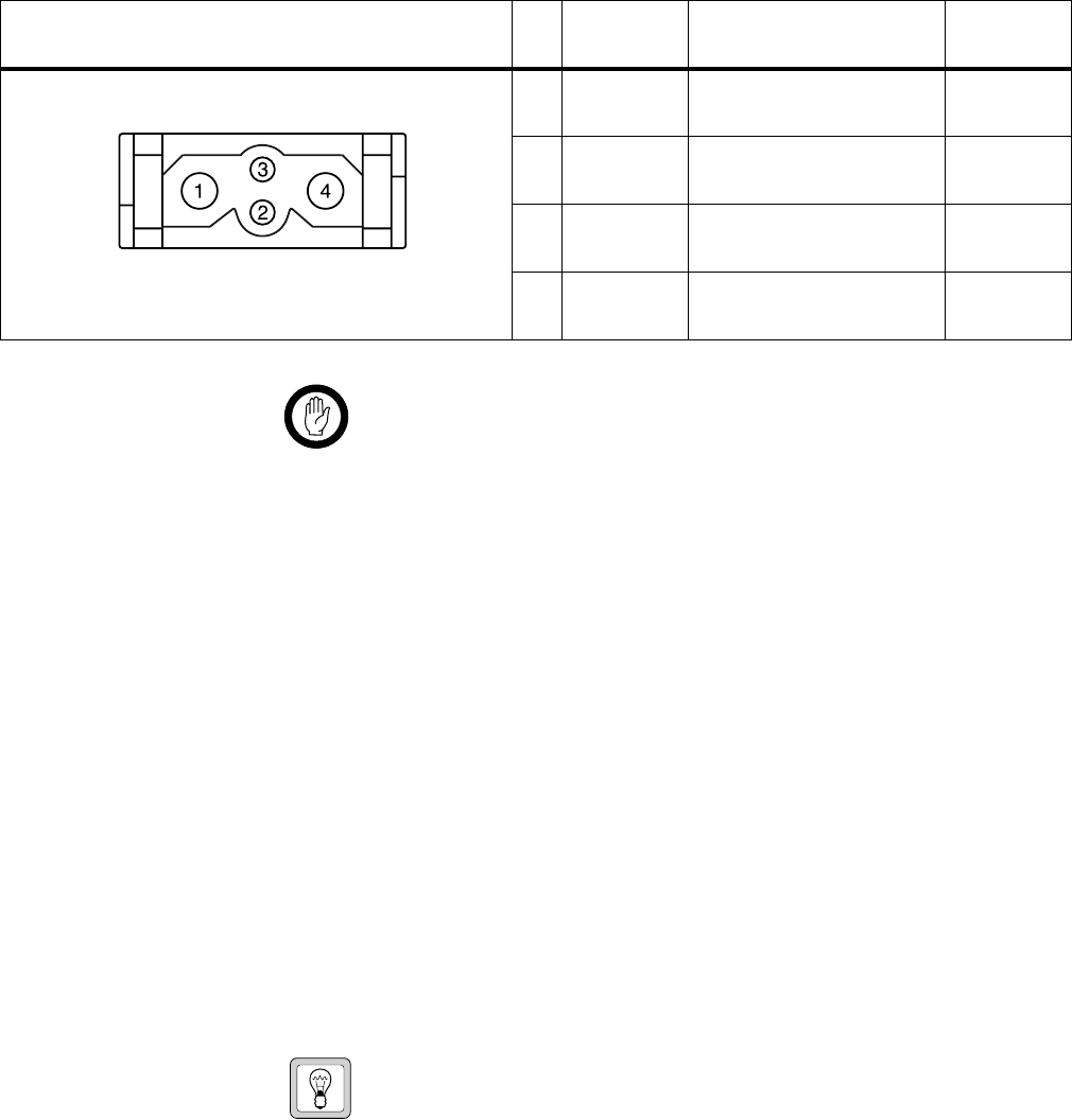
Table 2.1 Power connector (radio) - pins and signals
Pinout Pin Signal
name Description Signal type
1 AGND Earth return for radio body
power source. Ground
2 SPK– External speaker output.
Balanced load configuration. Analog
3 SPK+ External speaker output.
Balanced load configuration. Analog
4 13V8_BATT DC power input for radio body
and control head. Power
rear view

20 TM9100 (40W/50W) Installation Guide
© Tait Electronics Ltd October 2004
Connecting the Power Cable Important Although it is possible to connect the radio in line with the
vehicle ignition, this installation method is not recom-
mended, as it may draw too much current resulting in dam-
age to the vehicle wiring and steering column or ignition
switch. This may also cause the supply voltage of the radio
to drop below the specified level.
Important Disconnecting the vehicle’s battery may cause problems
with some electronic equipment, such as vehicle alarms,
engine management systems, and in-car entertainment sys-
tems. Check that the vehicle owner has the necessary infor-
mation to make all electronic equipment function correctly
after battery reconnection.
Important If the battery is not disconnected, exercise extreme caution
throughout the installation and install the fuses only when
the installation is ready to be checked (refer to “Checking
the Installation” on page 24).
1. Disconnect the vehicle’s battery unless specifically prohibited from
doing so by the customer, vehicle manufacturer, agent, or supplier
due to the type of electrical equipment fitted to the vehicle.
Important The cable must be routed in a manner that minimizes cou-
pling of electric vehicle systems such as alternators into the
radio.
Important Protect the power cable from engine heat, sharp edges and
from being pinched or crushed.
2. Run the power cable between the radio’s mounting position and the
power source and cut it to length, allowing approximately 8 inches
(20cm) excess at the radio end.
3. Plug the power cable into the power connector of the radio.
4. Cut the negative and the positive wires where the in-line fuse holders
will be placed (as close to the power source as possible).
Important Do not install the fuses until the installation is ready to be
checked.
5. Insert each end of the negative wire into one of the in-line fuse
holders and crimp them to force the metal contacts onto the wires.
6. Connect the negative wire to the battery ground.
7. Repeat step 4 for the positive wire and connect it to the positive
terminal of the power source.

TM9100 (40W/50W) Installation Guide 21
© Tait Electronics Ltd October 2004
2.7 Connecting a Remote Speaker
If a high-power remote speaker is required, the Tait TMAA10-03 speaker is
recommended. Connect the speaker to pins 2 (SPK–) and 3 (SPK+) of the
power connector described on page 19. For more information refer to the
fitting instructions provided with the speaker, or to the accessories manual.
2.8 Connecting to the Auxiliary Connector
Introduction The auxiliary connector can be used to connect external devices and signals
that are typically connected to a radio. These devices and signals include:
■the ignition signal to power up and down the radio
■an emergency switch to power up the radio (if required) and the enter
emergency mode
■external alert devices
Auxiliary Connector The radio’s auxiliary connector is a 15-way standard-density D-range
socket.
Note The space for a mating plug is limited to 1 5/8 inches (41mm) in
width and 11/16 inches (18mm) in height. It is recommended to
test the plug to be used before manufacturing a cable. Tait uses
IPN 240-00020-55 for the plug.
22 TM9100 (40W/50W) Installation Guide
© Tait Electronics Ltd October 2004
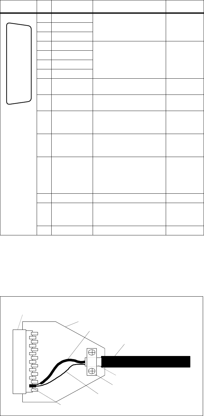
Shielding If the auxiliary cable is longer than 4 feet (1m) it is recommended to shield
the cable and connector backshell. Figure 2.4 shows the recommended
shielding arrangement. The earth braid wire (bare copper) and aluminium
foil should only be earthed at the radio end of the cable.
Table 2.2 Auxiliary connector (radio) - pins and signals
Pinout Pin Signal name Description Signal type
12 AUX_GPI1 General purpose digital
input. Programmable
function.
Digital,
3V3 CMOS.
5 AUX_GPI2
4 AUX_GPI3
10 AUX_GPIO4 Programmable function and
direction.
Pads available to fit a higher
power driver transistor on
GPIO4 line.
Digital, 3V3
CMOS input;
open collector
output with
pullup
2 AUX_GPIO5
9 AUX_GPIO6
1 AUX_GPIO7
11 AUX_TXD Asynchronous serial port -
Transmit data Digital,
3V3 CMOS
3 AUX_RXD Asynchronous serial port -
Receive data Digital,
3V3 CMOS
7 AUD_TAP_IN Programmable tap point into
the Rx or Tx audio chain.
DC-coupled.
Analog
13 AUD_TAP_OUT Programmable tap point out
of the Rx or Tx audio chain.
DC-coupled.
Analog
14 AUX_MIC_AUD Auxiliary microphone input.
Electret microphone biasing
provided. Dynamic
microphones are not
supported.
Analog
6 RSSI Analog RSSI output. Analog
8 +13V8_SW Switched 13.8V supply.
Supply is switched off when
radio body is switched off.
Power
15 AGND Analog ground Ground
rear view
J
B
C
D
E
F
G
H
I
1)
1!
1@
1#
1$
1%
Figure 2.4 Auxiliary cable and connector shielding
cable insulation
aluminum foil
earth braid wire
signal earth wire
analo
g
g
round pin
metal backshell
metal D-range shroud in
contact with backshell
metal cable clamp

TM9100 (40W/50W) Installation Guide 23
© Tait Electronics Ltd October 2004
Ignition Signal The radio can use the ignition signal to be powered up and down. This will
turn the radio off when the ignition key is off to avoid flattening the battery,
and will turn the radio on or return to its previous state (as programmed)
when the ignition key is on.
Note The AUX_GPI3 line must be programmed to ‘Power Sense
(Ignition)’ and active to ‘High’. For more information, refer to the
online help of the application software.
Connect the ignition signal to pin 4 (AUX_GPI3) of the auxiliary
connector.
Emergency Switch The radio allows for connection of an emergency switch to any input line
to enter the emergency mode. If connected to the AUX_GPI2 input line,
the radio can also use ‘emergency power sense’ to power up the radio in order
to enter the emergency mode.
Note The selected input line must be programmed to ‘Enter Emergency
Mode’ and active to ‘Low’. To use ‘emergency power sense’,
hardware link LK3 must be fitted (factory default), and AUX_GPI2
must be used. For more information, refer to the service manual
and the online help of the application software.
Connect a normally closed switch between the pin of the input line (pin 5
for AUX_GPI2) and pin 15 (AGND) of the auxiliary connector.
External Alert Device The radio allows for output to external alert devices using the digital GPIO
lines of the auxiliary connector and the internal options connector.
AUX_GPIO4 can be fitted with a power MOSFET (Q707) in order to
directly connect external alert devices (e.g. flashing light, buzzer, horn relay)
to the radio. Also, resistor R768 must be removed.
Important While the MOSFET is rated at 12A (with heat sink), the
maximum allowable current of the connector and radio’s
earthing system is 2A. Therefore, a horn must not be con-
nected directly to the radio. A horn relay must be used.
Note The selected output line must be programmed to ‘External Alert 1
or 2’, active to ‘Low’, and signal sate to ‘Momentary’.
Connect the external alert device to the pin of the output line (pin 10 for
AUX_GPIO4) and pin 8 (13V8_SW) of the auxiliary connector (or a
different positive battery connection).
24 TM9100 (40W/50W) Installation Guide
© Tait Electronics Ltd October 2004
2.9 Checking the Installation
1. Insert the fuses into the power leads.
2. Switch on the radio to confirm that it is operational, but do not
transmit.
3. Connect an in-line power meter between the radio and the antenna.
4. Place the radio in transmit mode and measure the forward and
reflected power levels.
5. Less than 4% of the forward power should be reflected. If this is not
achieved, check the installation, including the antenna length.
6. Start reducing the length of the antenna in steps of 0.1 inches to
0.2 inches (2 to 5mm); measure the power levels at each step.
7. Once the reflected power levels are within tolerance, make a call to
another party on the radio.