Tait TMAH7D Mobile Transceiver User Manual MMA 00003 02 user s guide
Tait Limited Mobile Transceiver MMA 00003 02 user s guide
Tait >
Exhibit D Users Manual per 2 1033 c3

MMA-00003-02 Issue 2
© Tait Electronics Ltd September 2004. All rights reserved. Directive 1999/5/EC Declaration
Directive 1999/5/EC Declaration of Conformity
da Dansk
Undertegnede Tait Electronics Ltd erklærer
herved, at følgende udstyr TMAB1C,
TMAD1C & TMAH5C overholder de
væsentlige krav og øvrige relevante krav i
direktiv 1999/5/EF.
Se endvidere: http://eudocs.taitworld.com/
de Deutsch
Hiermit erklärt Tait Electronics Ltd die Übere-
instimmung des Gerätes TMAB1C, TMAD1C
& TMAH5C mit den grundlegenden
Anforderungen und den anderen relevanten
Festlegungen der Richtlinie 1999/5/EG.
Siehe auch: http://eudocs.taitworld.com/
el Ελληνικός
Με την παρουσα Tait Electronics Ltd
δηλωνει οτι TMAB1C, TMAD1C &
TMAH5C συµµορφωνεται προσ τισ
ουσιωδεισ απαιτησεισ και τισ λοιπεσ
σχετικεσ διαταξεισ τησ οδηγιασ 1999/5/ΕΚ.
βλέπε και: http://eudocs.taitworld.com/
en English
Tait Electronics Ltd declares that this
TMAB1C, TMAD1C & TMAH5C complies
with the essential requirements and other
relevant provisions of Directive 1999/5/EC.
See also: http://eudocs.taitworld.com/
es Español
Por medio de la presente Tait Electronics Ltd
declara que el TMAB1C, TMAD1C &
TMAH5C cumple con los requisitos esen-
ciales y cualesquiera otras disposiciones apli-
cables o exigibles de la Directiva 1999/5/CE.
Vea también: http://eudocs.taitworld.com/
fi Suomi
Tait Electronics Ltd vakuuttaa täten että
TMAB1C, TMAD1C & TMAH5C tyyppinen
laite on direktiivin 1999/5/EY oleellisten
vaatimusten ja sitä koskevien direktiivin
muiden ehtojen mukainen.
Katso: http://eudocs.taitworld.com/
fr Français
Par la présente, Tait Electronics Ltd déclare
que l'appareil TMAB1C, TMAD1C &
TMAH5C est conforme aux exigences
essentielles et aux autres dispositions perti-
nentes de la directive 1999/5/CE.
Voir aussi: http://eudocs.taitworld.com/
it Italiano
Con la presente Tait Electronics Ltd dichiara
che questo TMAB1C, TMAD1C & TMAH5C
è conforme ai requisiti essenziali ed alle
altre disposizioni pertinenti stabilite dalla
direttiva 1999/5/CE.
Vedi anche: http://eudocs.taitworld.com/
nl Nederlands
Hierbij verklaart Tait Electronics Ltd dat het
toestel TMAB1C, TMAD1C & TMAH5C in
overeenstemming is met de essentiële
eisen en de andere relevante bepalingen
van richtlijn 1999/5/ EG.
Zie ook: http://eudocs.taitworld.com/
pt Português
Tait Electronics Ltd declara que este
TMAB1C, TMAD1C & TMAH5C está
conforme com os requisitos essenciais e
outras provisões da Directiva 1999/5/CE.
Veja também: http://eudocs.taitworld.com/
sv Svensk
Härmed intygar Tait Electronics Ltd att
denna TMAB1C, TMAD1C & TMAH5C står
I överensstämmelse med de väsentliga
egenskapskrav och övriga relevanta
bestämmelser som framgår av direktiv
1999/5/EG.
Se även: http://eudocs.taitworld.com/
2

About this guide 3
About this guide
This user’s guide provides information about TM8200 radios
and is divided into two parts.
■Part 1 explains how the TM8250 radio with the graphical
display operates.
■Part 2 outlines the installation procedure for all
TM8200 radios.
If you need further assistance or your radio does not operate
as you expect, contact your radio provider.
Important safety information
This user’s guide also contains important safety and compli-
ance information about using and installing TM8200 radios.
Refer to page 11 for user safety and compliance instructions
and page 42 for installation safety instructions.
Safety warnings used in this guide
Within this guide, the following conventions are used to alert
you to important safety information:
Warning: There is a potential risk of death or serious injury.
Caution: There is the risk of minor or moderate injury
to people.
Caution: “Caution” is used without the safety alert symbol
when there is a risk of equipment damage
or malfunction.
Feedback about this guide
If you have any enquiries regarding this guide, or any
comments, suggestions and notifications of errors, please
contact Technical Support at support@taitworld.com.

4About this guide
Changes to this guide
In the interests of improving the performance, reliability or
servicing of the equipment, Tait Electronics Ltd reserves the
right to update both the equipment or this user’s guide, with-
out prior notice.
Website: For contact details and technical assistance,
go to http://www.taitworld.com/, and
http://support.taitworld.com/.
Copyright information
All information contained in this guide is the property of Tait
Electronics Ltd. All rights are reserved. These guides may not,
in whole or in part, be copied, photocopied, reproduced,
translated, stored, or reduced to any electronic medium or
machine-readable form, without prior written permission
from Tait Electronics Ltd. All trade names referenced are the
service mark, trademark, or registered trademark of the
respective manufacturers.
Disclaimer
There are no warranties extended or granted by this guide.
Tait Electronics Ltd accepts no responsibility for damage aris-
ing from use of the information contained in the guide or of
the equipment and software it describes. It is the responsibil-
ity of the user to ensure that use of such information, equip-
ment and software complies with the laws, rules and
regulations of the applicable jurisdictions.
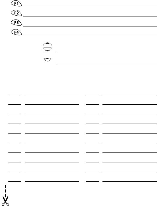
Your radio’s settings
Use the following table to list your radio’s programmed settings.
Frequently used channels and groups
Function key settings
quick access
menus:
ID Description ID Description
scroll keys
on/off key
volume
control
microphone
socket
press-to talk key
(PTT)
red
display speaker
green
amber
microphone
radio status LEDs
function keys
1 to 4 left selection key right selection key
Main menu
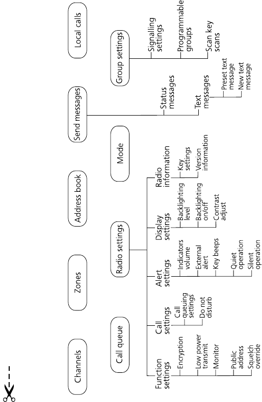
Navigating your radio’s menus
Main menu: conventional mode
Note: Only features programmed for your radio will be available.
Radio operation 9
Part 1: Radio operation
About this guide .......................................................................... 3
Important safety information ....................................................................... 3
Safety warnings used in this guide .............................................................. 3
Feedback about this guide .......................................................................... 3
Changes to this guide ................................................................................. 4
Copyright information ................................................................................. 4
Disclaimer .................................................................................................. 4
Safety and compliance warnings .............................................. 11
Radio frequency exposure information ...................................................... 11
Radio frequency emissions limits in the USA .............................................. 12
Health, safety and electromagnetic compatibility in Europe ........................ 13
Electromagnetic compatibility in European vehicles ................................... 13
EN 60950 requirements (25 watt radios) ................................................... 14
Safe radio operation ................................................................................. 14
High radio surface temperatures ............................................................... 14
Radio protection when changing the vehicle battery .................................. 14
Getting started ........................................................................... 15
Radio controls .......................................................................................... 15
Radio indicators ........................................................................................ 17
Navigating your radio’s menus .................................................................. 20
Viewing your radio’s function key settings ................................................. 21
Basic operation ........................................................................... 22
Turning the radio on and off ..................................................................... 22
Entering your personal identification number ............................................. 22
Adjusting the speaker volume ................................................................... 23
Turning on control-head backlighting ........................................................ 23
Operating in conventional mode .............................................. 25
Selecting a channel or scanning group ...................................................... 25
Selecting a zone ....................................................................................... 27
Checking that a channel is clear ................................................................ 28
Making a call ........................................................................................... 30
Making a local call ................................................................................... 31
10 Radio operation
Making a call using your address book ...................................................... 32
Making an emergency call ........................................................................ 34
Receiving a call ........................................................................................ 34
Hearing faint and noisy signals ................................................................. 34
Troubleshooting .........................................................................37
When your radio won’t turn on ................................................................. 37
Removing the microphone ........................................................................ 37
Removing the radio from the vehicle ......................................................... 38
Describing the radio’s audible tones .......................................................... 38
Notes ............................................................................................ 40
Safety and compliance warnings 11
Safety and compliance warnings
Radio frequency exposure information
For your own safety and to ensure you comply with the
Federal Communication Commission’s (FCC) radio
frequency (RF) exposure guidelines, please read the following
information before using this radio.
Using this radio
You should use this radio only for work-related purposes (it is
not authorized for any other use) and if you are fully aware
of, and can exercise control over, your exposure to RF energy.
To prevent exceeding FCC RF exposure limits, you must
control the amount and duration of RF that you and other
people are exposed to.
It is also important that you:
■Do not remove the RF exposure label from the radio.
■Ensure this RF exposure information accompanies the
radio when it is transferred to other users.
■Do not use the radio if you do not adhere to the guide-
lines on controlling your exposure to RF.
Controlling your exposure to RF energy
This radio emits RF energy or radio waves primarily when
calls are made. RF is a form of electromagnetic energy (as is
sunlight), and there are recommended levels of maximum
RF exposure.
To control your exposure to RF and comply with the maxi-
mum exposure limits for occupational/controlled environ-
ments, follow these guidelines:
■Do not talk (transmit) on the radio more than the rated
transmit duty cycle. This is important because the radio
radiates more energy when it is transmitting than when
it is receiving.

12 Safety and compliance warnings
■While you are transmitting (talking or sending data) on
the radio, you must ensure that there is always a distance
of 0.9m (35 inches) between people and the antenna.
This is the minimum safe distance.
■Use the radio only with Tait-approved antennas and
attachments, and make only authorized modifications to
the antenna otherwise you could damage the radio and
violate FCC regulations.
Website: For more information on what RF energy is
and how to control your exposure to it, go to
http://www.fcc.gov/oet/rfsafety/rf-faqs.html.
Compliance with RF energy exposure
standards
This two-way radio complies with these RF energy exposure
standards and guidelines:
■United States Federal Communications Commission,
Code of Federal Regulations; 47 CFR 1.1307, 1.1310
and 2.1091
■American National Standards Institute (ANSI) / Institute
of Electrical and Electronic Engineers (IEEE) C95. 1-1992
■Institute of Electrical and Electronic Engineers (IEEE)
C95.1-1999 Edition.
This radio complies with the IEEE (FCC) and ICNIRP exposure
limits for occupational/controlled RF exposure environments
at operating duty factors of up to 50% talk to 50% listen.
Radio frequency emissions limits in the USA
Part 15 of the FCC Rules imposes RF emission limits on elec-
tronic equipment to prevent interference to reception of
broadcast services.
This device complies with Part 15 of the FCC Rules. Opera-
tion is subject to the condition that this device does not
cause harmful interference.

Safety and compliance warnings 13
Note: Changes or modifications to this device that are not
expressly approved by Tait Electronics Ltd may make
its use illegal.
Health, safety and electromagnetic compatibility
in Europe
In the European Community, radio and telecommunications
equipment is regulated by Directive 1999/5/EC, also known
as the Radio and Telecommunications Terminal Equipment
(R&TTE) directive. The requirements of this directive include
protection of health and safety of users, as well as
electromagnetic compatibility.
Intended purpose of product
This product is an FM radio transceiver. Its intended purpose
is for radio communication in Private Mobile Radio (PMR)
services or Public Access Mobile Radio (PAMR) services.
Note: This product can be programmed for frequencies or
emissions that may make its use illegal. Where appli-
cable, a license must be obtained before this product
is used. All license requirements must be observed.
Limitations may apply to transmitter power, operating
frequency, channel spacing, and emission.
Declaration of conformity
Brief Declarations of Conformity appear on page 1.
Website: To download the formal declaration of
conformity, go to http://eudocs.taitworld.com/.
A signed and dated paper copy of the declaration of
conformity can be obtained from Tait Europe Ltd.
Electromagnetic compatibility in European vehicles
In the European Community, radio equipment fitted to auto-
motive vehicles is regulated by Directive 72/245/EEC, as
amended by 95/54/EC. The requirements of this directive

14 Safety and compliance warnings
cover the electromagnetic compatibility of electrical or elec-
tronic equipment fitted to automotive vehicles.
Note:
To meet the requirements of Directive 72/245/EEC (as
amended by 95/54/EC) installation of this product in a
vehicle must be performed according to the instructions
provided, and any guidelines of the vehicle manufacturer.
EN 60950 requirements (25 watt radios)
This radio complies with the European Union standard
EN 60950 when operated up to the rated 33% duty cycle of
two minutes transmit and four minutes receive, and with
ambient temperatures of 30°C or lower.
Caution: Operation outside these limits may cause the
external temperature of the radio to rise higher
than this standard permits.
Safe radio operation
Warning: Observe the following safe operating practices:
■Switch the radio off at petrol filling stations or near flam-
mable liquids or gases.
■Switch the radio off in the vicinity of explosive devices
and blasting zones.
■
Using a handheld microphone or a radio while driving a vehi-
cle may violate the laws and legislation that apply in your
country or state. Please check the regulations in your area.
High radio surface temperatures
The bottom surface of the radio and the heatsink fins can
become hot during prolonged operation. Do not touch these
parts of the radio.
Radio protection when changing the vehicle battery
Always remove the fuses from the radio power cable before
charging the vehicle battery, connecting a second battery or using
power from another vehicle (e.g. when jump-starting the vehicle).
Getting started 15
Getting started
This section provides a brief description of your radio’s
controls and indicators and explains how to use the
radio’s menus.
The following topics are covered in this section:
■radio controls
■radio indicators
■navigating your radio’s menus
■viewing your radio’s function key settings.
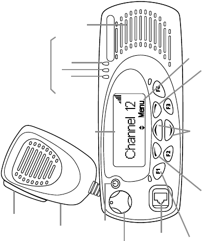
Radio controls
The radio controls are the PTT key, volume control, on/off key,
scroll keys, selection keys and function keys. Some keys may
have functions assigned to both short and long key presses:
■a short key press is less than one second, and
■a long key press is more than one second.
The radio controls and their functions are summarized in
the following diagram.
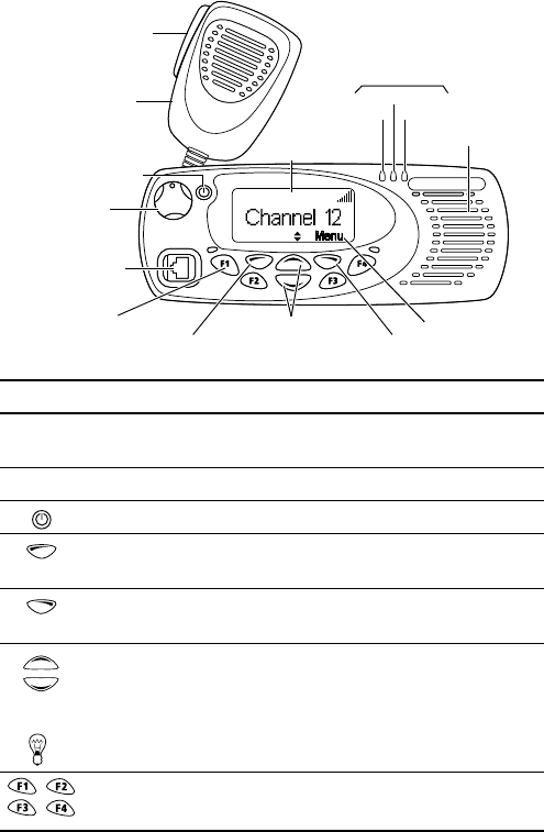
16 Getting started
scroll keys
on/off key
volume
control
microphone
socket
press-to-talk
(PTT) key
red
display speaker
green
amber
microphone
radio status LEDs
function keys
1 to 4 left selection key right selection key
Main menu
Symbol Name Function
PTT key press and hold to transmit and release
to listen
volume control rotate to change the speaker volume
on/off key turn the radio on or off with a long press
left selection key action determined by the text above the left
selection key
right selection key action determined by the text above the
right selection key
scroll keys
scroll up and down through a list of menu
options or scroll left and right in messages, or
access your Quick Access menu
Tip: If you press and hold the scroll keys, the scroll speed increases.
function keys
1, 2, 3 and 4
function keys with programmed options
Getting started 17
Radio indicators
The radio display, LED indicators and the radio’s audible
tones all combine to give you information about the state
of your radio.
The most common operation of the radio display and indica-
tors is described in the following sections.
Note: The way these indicators behave may be affected by
the way your radio is programmed.
Radio display
The messages and icons you see in your display depend on
the radio’s current operating mode, and the way the radio
was programmed.
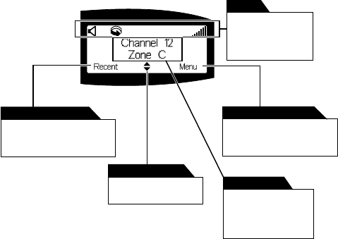
The following diagram shows a typical display in conventional
mode, explaining some of the display information available.
This text shows the current
function of the right
selection key.
right selection key text
This text shows the current
function of the left
selection key.
left selection key text
This appears when
scrolling is allowed
scrolling indicator
The icons along the
top of the display
show which
functions are active.
icon bar
This display appears
by default when the
radio is muted and
waiting for a call.
default display
18 Getting started
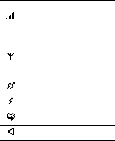
Radio display icons
Icon Meaning
received signal strength indicator (RSSI) (green
LED glowing): the more bars on this indicator, the
stronger the signal being received by your radio.
transmit power level (red LED glowing): the more
bars on the indicator, the higher the power level
of your transmission
MPT network: your radio has access to an
MPT network
flashing: your radio is attempting to access
an MPT network
transmit: your radio is transmitting
low-power transmit: your radio is transmitting
on low power
scanning: your radio is monitoring a group of
channels for activity
monitor or squelch override: monitor or squelch
override is active

Getting started 19
LED indicators
Audible tones
Note: If quiet or silent mode has been turned on, you will
not hear any audible tones.
For a description of other tones you may hear, see “Describ-
ing the radio’s audible tones” on page 38.
LED Meaning
red
(transmit)
glowing: your radio is transmitting
flashing: your transmit timer is about to expire, or
your radio is stunned, or
your call time is about to expire (MPT trunked mode)
green
(receive)
glowing: you are receiving
flashing: you have received a call
amber
(scanning or
network)
glowing: your radio is scanning a group of
channels for activity (conventional mode) or
network service is available (MPT trunked mode)
flashing: your radio has detected activity on a
channel, and has halted on this channel
(conventional mode)
flashing fast: there is no network service
available
(MPT trunked mode)
Tone type Meaning
one short
beep
valid key press: the action you have attempted
is permitted, or
function activated: a function key has been
pressed and that function has been activated
one long,
low-pitched
beep
invalid key press: the action you have
attempted is not permitted, or
transmission inhibited: you have attempted to
transmit but for some reason transmission is
not permitted at this time
one short,
low-pitched
beep
function deactivated: a function key has been
pressed and the corresponding function has
been turned off
20 Getting started
Navigating your radio’s menus
Your radio has a number of menus available, each containing
lists or submenus. The menus available will depend on the
way your radio is programmed.
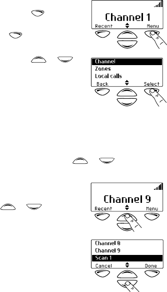
Using the Main menu
Whenever Menu appears above the
right selection key , you are
able to open the Main menu
by pressing .
Use the scroll keys or to
move through the list of menus.
When the menu you want is high-
lighted, press Select to open the
menu you have chosen.
Using the scroll key Quick Access menu
Your radio may be programmed so that your scroll keys act as
a shortcut to a frequently used menu. To go to this Quick
Access menu, press a scroll key or , and the Quick
Access menu appears.
For example, if your Channels menu
is your Quick Access menu, press a
scroll key or to go directly
to the Channels menu.
The Channels menu, with a list of
your available channels and scan
groups, is now displayed.
Getting started 21
Using the left selection key Quick Access menu
Your radio may be programmed
so that your left selection key acts as
a shortcut to another frequently
used menu. If this menu has been
programmed, the text for left selec-
tion key corresponds to the menu.
To use this Quick Access menu, press your left
selection key , and the associated menu appears.
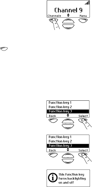
Viewing your radio’s function key settings
Your radio’s four function keys can have programmed func-
tions assigned to each key. Some keys may have a function
associated with both a short key press and a long key press.
To check the functions assigned to your radio’s function keys,
you can use the Main menu.
1Select Main>Radio Information>
Key Settings.
2In the Key Settings menu, scroll
through the list of function keys.
3Press Select to view details of
the function associated with a
particular function key.
The example shown is for a func-
tion key programmed to turn
control-head backlighting on
and off.
22 Basic operation
Basic operation
This section describes the basic operations of your radio.
The following topics are covered in this section:
■turning the radio on and off
■entering your personal identification number
■adjusting the speaker volume
■turning on control-head backlighting.
Turning the radio on and off
Give a long press of the on/off key to turn the radio either
on or off.
When the radio is first turned on, the red, green and amber
LEDs flash briefly and the radio gives two short beeps. A brief
message may appear on the display.
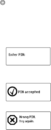
Entering your personal identification number
You may need to enter a personal
identification number (PIN) before
you can use your radio. If the
message Enter PIN: appears, enter
your assigned PIN.
Once you have entered your PIN
correctly, the PIN accepted
message appears and normal opera-
tion is now possible.
If you do not know your PIN or you
receive an incorrect PIN message,
consult your radio provider
or administrator.
Basic operation 23
Adjusting the speaker volume
Rotate the volume control clockwise to increase the
speaker volume and counterclockwise to decrease the
volume. The volume control also changes the volume level
of the radio’s audible indicators.
Note: Your radio may be programmed with a minimum
volume level.
Turning on control-head backlighting
The radio’s display and keypad light up when backlighting is
on. This normally only happens when a key is pressed or a
call is received. There are two ways you may be able to
change the way backlighting operates on your radio:
■turn on backlighting momentarily, using a programmed
function key, or
■toggle backlighting between on and off, using either a
programmed function key or the Main menu.
Turning backlighting on momentarily by using
a function key
You may be able to use a programmed function key to turn
backlighting on momentarily. Backlighting remains on for a
few seconds and then turns off.
Alternatively, the function key may be programmed so that:
■a short key press turns backlighting on momentarily, and
■a long key press turns backlighting on, and it remains on
until there is a further long key press.
Toggling backlighting on and off by using a
function key
The function key programmed for backlighting toggles the
backlighting between on and off. When backlighting is
turned on, it remains on until the function key is
pressed again.
24 Basic operation
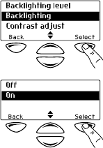
Toggling backlighting on and off by using the
Main menu
When backlighting is turned on using the menu, it remains on
until the setting is changed to off, regardless of radio activity.
1Select Menu>Radio Settings>
Display Settings>Backlighting.
2In the Backlighting menu, chose
either On or Off.
3Press Select.
Operating in conventional mode 25
Operating in conventional mode
The following topics are covered in this section:
■selecting a channel or scanning group
■selecting a zone
■checking that a channel is clear
■making a call
■making a local call
■making a call using your address book
■making an emergency call
■receiving a call
■hearing faint and noisy signals.
Selecting a channel or scanning group
To select a channel or scanning group you may be able
to either:
■use a programmed function key,
■use the Main menu, or
■use your quick access menu.
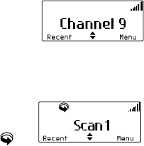
Selecting a channel by using a programmed
function key
Press the function key programmed for preset channel.
The programmed channel is now
shown in the display.
Selecting a scan group by using a programmed
function key
Press the function key programmed for group scanning.
The programmed scan group is now
shown in the display, the amber LED
glows and the scanning icon
appears in the icon bar.
26 Operating in conventional mode
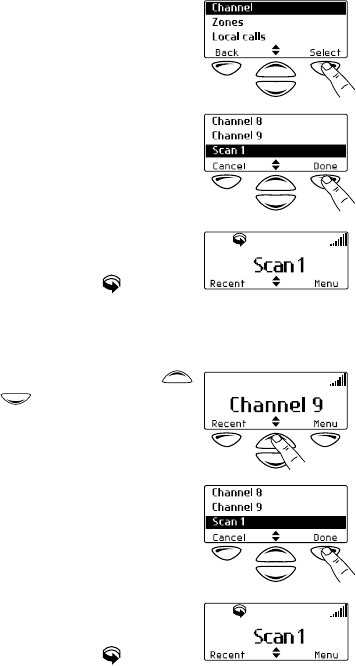
Selecting a channel or scan group by using
the Main menu
1Select Menu>Channels.
2In the Channels menu, scroll
through the list of channels and
scan groups until the channel or
scan group you want appears.
3Press Done.
If you have selected a scan
group, the amber LED glows and
the scanning icon appears in
the icon bar.
Selecting a channel or scan group by using
your Quick Access menu
1Press one of the scroll keys
or to open the
Channels menu.
2Scroll through the list of chan-
nels and scan groups until the
channel or scan group you
want appears.
3Press Done.
If you have selected a scan
group, the amber LED glows and
the scanning icon appears in
the icon bar.
Operating in conventional mode 27
Selecting a zone
A zone is a collection of channels. To select a zone you may
be able to either:
■use the Main menu, or
■use your Quick Access menu.
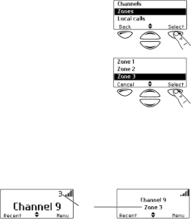
Selecting a zone by using the Main menu
1Select Menu>Zones.
2In the Zones menu, scroll
through the list of zones until the
one you want appears.
3Press Select.
Your radio may now display the zone information in
two ways:
— the zone icon appears in the icon bar
— the zone indication appears below the
channel information.
zone
information
28 Operating in conventional mode
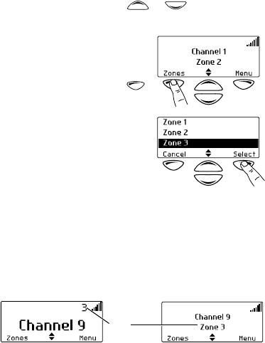
Selecting a zone by using your Quick
Access menu
1Press one of the scroll keys or to open the
Zones menu.
Alternatively, the left selection
key may be programmed as your
Quick Access menu. In this case,
press the left selection key
to access the Zones menu.
2Scroll through the list of zones
until the zone you want appears.
3Press Select.
Your radio may now display the zone information in
two ways:
— the zone icon appears in the icon bar
— the zone indication appears below the
channel information.
Checking that a channel is clear
You or your user group may be segregated from other user
groups by special signalling. If an incoming call carries the
special signalling tones specific to you or your user group,
your radio’s signalling mute opens and you can hear the call.
These tones may not be audible.
The monitor function allows you to override any special
signalling on a channel, so that you can check that the chan-
nel is clear before you make a call.
zone
information
Operating in conventional mode 29
Note: Your radio may be programmed to activate monitor
whenever the microphone is off the microphone clip.
To activate monitor, you may be able to either:
■remove the microphone from the microphone clip,
■use a programmed function key, or
■use the Main menu.
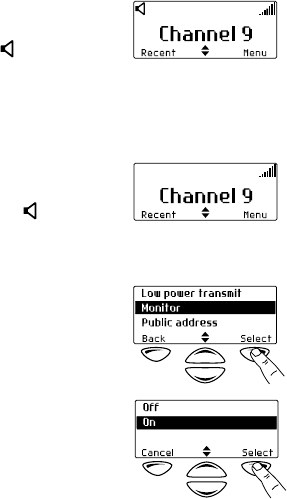
Activating monitor by using a function key
1Press the monitor function key to activate monitor and
hear any traffic on the channel.
While monitor is on, the green
LED flashes continually and the
monitor icon appears in
the icon bar.
2Press the monitor function key again to turn monitor off,
or wait for monitor to turn off automatically, after a
programmed delay.
When monitor turns off, the
green LED stops flashing and
the monitor icon disappears
from the icon bar.
Activating monitor by using the Main menu
1Select Menu>Radio Settings>
Function Settings>Monitor.
2In the Monitor menu,
choose On.
30 Operating in conventional mode
3Press Select.
While monitor is on, the green
LED flashes continually and the
monitor icon appears in
the icon bar.
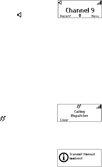
Making a call
1Select the required channel or scan group.
2Check that the channel is clear. If the green LED is glowing,
the channel is busy and you may not be able to transmit.
3Once the channel is clear (the green LED is off), lift the
microphone off the microphone clip.
4Hold the microphone about 5cm (2 inches) from your
mouth and press the PTT key to transmit.
5Speak clearly into the microphone and release the PTT
key when you have finished talking.
While you are transmitting, the
red LED glows and the transmit
icon appears in the icon bar.
Transmit timer
Your radio may have a transmit timer that limits the amount
of time you can transmit continuously.
When the transmit timer is about to
expire, the message Transmit
timeout imminent appears in the
display, the red LED flashes and the
radio gives three beeps.
You must release the PTT before you can transmit again.
Note: Your radio may be unable to transmit for a short time
after the transmit timer has expired.
Operating in conventional mode 31
Making a local call
Each channel on your radio may have one or more local calls
programmed. To make a local call you may be able to either:
■use a programmed function key,
■use the Main menu, or
■use your Quick Access menu.
Making a local call by using a function key
1Select the required channel.
2Press the function key programmed for the local call
you want.
The call details appear in the
display, the red LED glows and
the transmit icon appears in
the icon bar.
Making a local call by using the Main menu
1Select the required channel.
2Select Menu>Local Calls.
3In the Local Calls menu, scroll
through the list of local calls until
the call you want appears.
4Press Send.
The call details appear in the
display, the red LED glows and
the transmit icon appears in
the icon bar.
32 Operating in conventional mode
Making a local call by using your Quick
Access menu
1Select the required channel.
2Press one of the scroll keys
or to open the
Local Calls menu.
3Scroll through the list of local
calls until the call you
want appears.
4Press Send.
The call details appear in the
display, the red LED glows and
the transmit icon appears in
the icon bar.
Making a call using your address book
Your Address Book menu has a programmed list of calls,
which can be made from any channel or zone. Address-book
calls may also be used to send status information, such as
“at lunch” or “on site”.
To make a call using your address book, you may be able
to either:
■use a programmed function key,
■use the Main menu, or
■use your Quick Access menu.
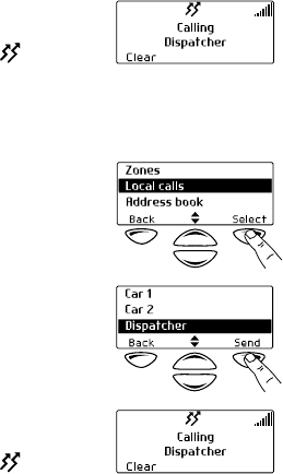
Making an address-book call by using a
function key
Press the function key programmed to make a call from your
address book.
Operating in conventional mode 33
The call details appear in the display,
the red LED glows and the
transmit icon appears in the icon
bar.
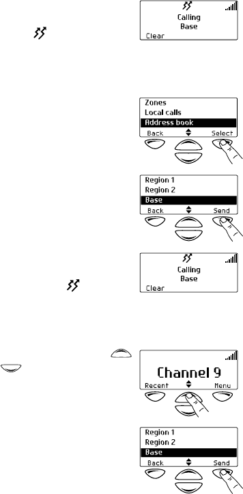
Making an address-book call by using the
Main menu
1Select Menu>Address Book.
2In the Address Book menu, scroll
through the list of calls until the
call you want appears.
3Press Send.
The call details appear in the
display, the red LED glows and
the transmit icon appears in
the icon bar.
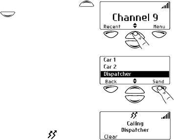
Making an address-book call by using your
Quick Access menu
1Press one of the scroll keys
or to open the
Address Book menu.
2Scroll through the list of calls
until the call you want appears.

34 Operating in conventional mode
3Press Send.
The call details appear in the
display, the red LED glows and
the transmit icon appears in
the icon bar.
Making an emergency call
You may be able to activate emergency mode by using a
programmed function key.
1Press the function key programmed for emergency mode
and an emergency call is sent to your dispatcher, or some
other predetermined location.
While emergency mode is active, your radio may cycle
between receive and transmit, so that your dispatcher
can hear any activity near the radio. Alternatively, your
radio may appear to turn off but will actually remain in
emergency mode.
2Reset the radio to normal operation at any time by turn-
ing the radio off and then on.
Receiving a call
When there is valid activity on your radio’s currently selected
channel or group, the radio then unmutes and you can
hear the call.
If the incoming call contains special signalling that matches
the signalling programmed for your radio, the green LED
flashes and your radio may give a ringing tone.
Hearing faint and noisy signals
Your radio’s squelch allows the radio to unmute only when
the strength of the incoming signal is above a predetermined
threshold. This means that only signals of reasonable intelli-
gibility are made audible. To make faint and noisy signals
audible, use the squelch override function to unmute
the radio.
Operating in conventional mode 35
To activate squelch override, you may be able to either:
■use a programmed function key, or
■use the Main menu.
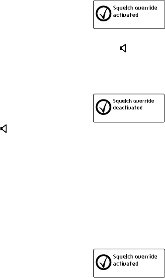
Turning squelch override on and off by using a
function key
1Press the function key programmed for squelch override
to unmute the radio.
The message Squelch override
activated appears on
the display.
While squelch override is on, the green LED flashes
continually and the squelch override icon appears in
the icon bar.
2To turn squelch override off, press the squelch override
function key again.
The message Squelch override
deactivated appears in the
display. The squelch override
icon disappears from the icon
bar and the green LED stops flashing.
Turning squelch override on and off by using
the function key programmed for monitor
The function key programmed for monitor may be
programmed so that:
■a short key press turns monitor on, and
■a long key press turns squelch override on.
Press and hold the function key programmed for monitor to
override the radio’s squelch.
The message Squelch override
activated appears in the display.
36 Operating in conventional mode
While squelch override is on, the green LED flashes continu-
ally and the squelch override icon appears in the icon bar.
Squelch override remains on until there is a further long
key press.
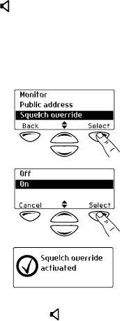
Activating squelch override by using the
Main menu
1Select Menu>Radio Settings>
Function Settings>
Squelch Override.
2In the Squelch Override menu,
chose On then press Select.
The message Squelch override
activated appears in
the display.
While squelch override is on, the green LED flashes
continually and the squelch override icon appears in
the icon bar.

Troubleshooting 37
Troubleshooting
The following topics are covered in this section:
■when your radio won’t turn on
■removing the microphone
■removing the radio from the vehicle
■describing the radio’s audible tones.
When your radio won’t turn on
If the red, green and amber LEDs on the control head do not
light up when the radio is turned on, it is likely that no power
is reaching the radio. Check the following:
■Is the power connector firmly plugged into the rear of
the radio?
■Are the in-line fuses in good condition?
■Is the power cable securely connected to the vehicle bat-
tery or power supply?
If all appears to be in order, then contact your radio provider
for further assistance.
Removing the microphone
1
Using your thumb or forefinger, lift up one
of the corners of the microphone grom-
met. Firmly (but gently) pull that corner
until the seal comes away from the cavity.
2Repeat to expose another corner.
3Pull the exposed corners back and slide the grommet up
the microphone cable to reveal the microphone plug.
4Remove the plug from the microphone socket.
Caution: The microphone grommet must be installed when-
ever the microphone is plugged into the micro-
phone socket. When installing a microphone,
follow the instructions in the section “Installing
the microphone” on page 49.
grommet
38 Troubleshooting
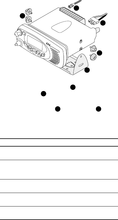
Removing the radio from the vehicle
1Switch off the radio.
2Unscrew the four thumb screws that secure the radio
to the U-bracket .
3Carefully lift the radio clear of the U-bracket.
4Disconnect the antenna and power cable from
the rear of the radio.
Describing the radio’s audible tones
The following table summarizes the radio’s audible tones.
c
d
a
a
b
a
b
cd
Action and tone Meaning
two short
beeps
radio turned on: the radio is powered on
and ready to use
one short beep after
the power-up beeps
radio locked: you need to enter your
personal identity number (PIN) before
you can use the radio
one long, low-
pitched beep
radio PIN entry unsuccessful: you need
to re-enter your PIN
two short beeps radio PIN entry successful: the radio is
now ready to use
one short beep
function activated: a function key has been
pressed and that function has been initiated

Troubleshooting 39
one short, low-
pitched beep
function deactivated: a function key has
been pressed and the corresponding
function has been turned off
one long, low-
pitched beep
invalid key press: the action you have
attempted is not permitted, or
transmission inhibited: you have
attempted to transmit but for some reason
transmission is not permitted at this time
one short, high-
pitched beep
radio is stunned: the radio has been
made inoperable by your service provider
two short beeps radio is revived: the radio has made
operable by your service provider
three beeps transmit timeout imminent: in
10 seconds your transmit timer will
expire and your current transmission will
be terminated
two low-
pitched beeps
radio's temperature is high: the radio's
temperature is in the high-temperature
range, but the radio will continue to operate
two high-
pitched beeps
radio's temperature is very high: the
radio's temperature is in the very high
temperature range and all transmissions
will now be at low power; if the radio's
temperature rises outside this range,
transmissions will be inhibited
continuous low-
pitched tone
radio system error: a system error has
occurred and the radio may
be inoperable
two long low-high
pitched tone pairs
synthesizer is out-of-lock: the radio's
synthesizer is out-of-lock on the current
channel and you cannot operate on
that channel
Action and tone Meaning
40 Notes
Notes
Radio installation procedures 41
Part 2: Radio installation procedures
Installation warnings ................................................................. 42
Safe radio mounting ................................................................................. 42
Interference with the vehicle’s electronic systems ...................................... 42
Preparation when drilling holes ................................................................. 43
Vehicles powered by liquefied petroleum gas (LPG) ................................... 43
Radio installation in gas or fuel tankers ..................................................... 43
Non-standard radio installations ............................................................... 44
Negative ground supply ............................................................................ 44
Installation planning .................................................................. 45
MPT 1362 code of practice ....................................................................... 45
Checking equipment ................................................................................. 45
Installation tools ....................................................................................... 46
Selecting the mounting position ................................................................ 46
Radio Installation ....................................................................... 47
Installing and removing the control head .................................................. 47
Installing the microphone ......................................................................... 49
Installing the antenna ............................................................................... 50
Installing the power cable ......................................................................... 51
Mounting the U-bracket ........................................................................... 53
Installing the radio in the U-bracket .......................................................... 54
Checking the installation .......................................................................... 54
Other installation options ......................................................................... 55
Tait general software licence agreement ................................. 56

42 Installation warnings
Installation warnings
The following topics are covered in this section:
■safe radio mounting
■interference with the vehicle’s electronic systems
■preparation when drilling holes
■vehicles powered by liquefied petroleum gas (LPG)
■radio installation in gas or fuel tankers
■non-standard radio installations
■negative ground supply.
Safe radio mounting
Caution: Mount the radio securely so that it will not break
loose in the event of a collision. An unsecured
radio is dangerous to the vehicle occupants.
■Mount the radio where it will not interfere with the
deployment of passenger air bags.
■Do not mount the radio vertically, with the control head
facing down. This will violate compliance with the Euro-
pean Union standard EN 60950, Safety of Information
Technology Equipment.
Interference with the vehicle’s electronic systems
Caution: Some vehicular electronic devices may be prone to
malfunction, due to the lack of protection from RF
energy present when your radio is transmitting.
Examples of vehicular electronic devices that may be affected
by RF energy are:
■electronic fuel injection systems
■electronic anti-skid braking systems
■electronic cruise control systems.

Installation warnings 43
If the vehicle contains such equipment, consult the vehicle
manufacturer or dealer in order to determine whether these
electronic circuits will perform normally when the radio
is transmitting.
Preparation when drilling holes
Caution: When drilling holes in the vehicle, check that drill-
ing at the selected points will not damage existing
wiring, petrol tanks, fuel lines, brake pipes or
battery cables.
Vehicles powered by liquefied petroleum gas (LPG)
Caution: Radio installation in vehicles powered by LPG with
the LPG container in a sealed-off space within the
interior of the vehicle must conform to the
National Fire Protection Association Standard
NFPA 58. This standard states that the radio
equipment installation must meet the
following requirements.
■The space containing the radio equipment shall be iso-
lated by a seal from the space containing the LPG con-
tainer and its fitting.
■Outside filling connections shall be used for the LPG con-
tainer and its fittings.
■The LPG container space shall be vented to the outside of
the vehicle.
Radio installation in gas or fuel tankers
Special conditions must be observed when installing a radio
in gas and fuel tankers. Consult your radio provider or
Tait-accredited service centre for more details.
44 Installation warnings
Non-standard radio installations
The installation U-bracket described in this guide has been
designed so that there is enough airflow around the radio
to provide cooling.
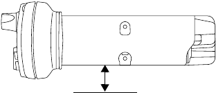
If a non-standard installation method is used, care must
be taken that sufficient heat can be dissipated from the
radio heatsink fins and the bottom surface of the
radio chassis.
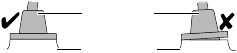
For this to be achieved, there must be a gap of more than
10mm (3/8 inch) between the bottom surface of the radio
chassis and the mounting surface. This is illustrated in the
following diagram.
Negative ground supply
TM8200 radios are designed to operate only in a negative
ground system.
10mm (3/8 inch)
mounting surface

Installation planning 45
Installation planning
The procedures outlined in this and the following sections
are for installing a TM8200 radio in a vehicle, using a
standard U-bracket.
The following topics are covered in this section:
■MPT 1362 code of practice
■checking equipment
■installation tools
■selecting the mounting position.
MPT 1362 code of practice
TM8200 radios should be installed in accordance with the
MPT 1362 Code of Practice. This code of practice covers the
installation of mobile radio equipment in land based vehicles
and has been developed by the United Kingdom Radiocom-
munications Agency.
Website: For the full text of the MPT 1362 Code of
Practice, go to the Radiocommunications Agency
website, http://www.radio.gov.uk.
Checking equipment
Unpack the radio and check that you have the following items:
■radio control head with connecting loom
■radio body
■microphone with microphone clip and screws
■U-bracket installation kit, consisting of:
—U-bracket
—thumbscrews
— self-drilling screws and washers
— power cable with DC connector
— 10A fuses (25W radios)
— 20A fuses (40W/50W radios)
46 Installation planning
— fuse holders
— receptacles for a remote speaker (speaker not included)
— BNC or mini-UHF antenna plug.
Installation tools
The following installation tools may be required:
■portable drill and drill bit
■Pozidriv screwdriver
■8mm (5/16 inch) socket (or Pozidriv screwdriver)
■BNC or mini-UHF crimp tool
■fuse crimp tool
■in-line RF power meter capable of measuring forward and
reflected power at the operating frequency of the radio.
Microphone clip installation tools
The following installation tools may be required for installing
the microphone:
■centre punch
■drill bit
■Pozidriv screwdriver
■hammer.
Selecting the mounting position
Inspect the vehicle and determine the safest and most
convenient location for mounting the radio.
The installation must meet the following requirements:
■sufficient clearance behind the radio for the heatsink
and cables
■a large enough flat surface so that the mounting bracket
will not be distorted
■no danger of the radio interfering with air
bag deployment.

Radio Installation 47
Radio Installation
The following topics are covered in this section:
■installing and removing the control head
■installing the microphone
■installing the antenna
■installing the power cable
■mounting the U-bracket
■installing the radio in the U-bracket
■checking the installation
■other installation options.
Installing and removing the control head
Caution: The control head contains devices which can be
damaged by static discharges. Always install or
remove the control head in a static-
safe environment.
Website: For information on antistatic precautions,
go to the Electrostatic Discharge Association (ESD)
website, http://www.esda.org.
Installing the control head on the radio body
Note: The way in which the U-bracket is mounted deter-
mines which way up the control head is mounted on
the radio body.
The numbers in the diagram on the following page refer to
the numbered steps below.
1Plug the control head loom onto the control
head connector.
2Insert the bottom edge of the control head onto the
two clips in the front of the radio chassis, then snap
into place.
48 Radio Installation
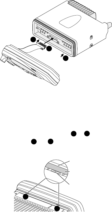
Removing the control head
Caution: During this procedure, take care that the control-
head seal is not damaged. Damage to this seal
reduces environmental protection.
1On the underside of the radio, insert a 5mm (3/16 inch)
flat-bladed screwdriver between the control head and the
control-head seal, in either position or .
Insertion points and are lever points and are indi-
cated on the radio chassis by a dot-dash-dot
pattern (•–•).
2Use the screwdriver to lift the control head off the chassis
clip, then repeat in the other position. The control head
can now be removed from the radio body.
2
1
2
12
12
lever point
control-head seal
indication of
lever point
1
2
Radio Installation 49
Installing the microphone
A microphone and microphone clip are only used for radios
with a user interface.
Caution: The microphone grommet must be installed when-
ever the microphone is plugged into the micro-
phone socket. When installed, the grommet has
two functions:
■to prevent damage to the microphone socket when there
is movement of the microphone cord, and
■to ensure that the control head is sealed against water,
dust and other environmental hazards.
To install the microphone:
1Plug the microphone into the microphone socket.
2Slide the microphone grommet along the microphone
cord and push two adjacent corners of the grommet into
the microphone socket cavity.
3Squeeze the grommet and push the remaining corners
into position.
4Check that the grommet is seated correctly in the cavity.
Installing the microphone clip
Caution: Only install the microphone clip provided. If a non-
standard microphone clip is used, the correct oper-
ation of the microphone hookswitch cannot
be guaranteed.
Install the microphone clip in the most convenient location
for the radio user. It must be installed:
■within easy reach of the user, and
■in such a position that the microphone PTT key cannot be
inadvertently activated or jammed on.
microphone
grommet
control head

50 Radio Installation
Installing the antenna
Install the external antenna according to the supplier’s
instructions. Good quality 50 ohm coaxial cable must be
used, such as RG58 or UR76.
Caution: The cable should be routed in a manner that mini-
mizes coupling into the electronic control systems
of the vehicle.
Caution: Avoid sharp bends in the cable. These distort the
cable and alter its electrical characteristics.
Warning: RF exposure hazard
To comply with FCC RF exposure limits:
1Mount the antenna at a location such that no person or
persons can come closer than 0.9m (35 inches) to
the antenna.
2For 25W radios, the radio must be installed using an
externally mounted antenna with a gain of either a
2.15dBi or 5.15dBi gain.
3For 40W/50W radios:
— VHF radios must be installed using an antenna
mounted centrally on the vehicle roof, with a gain of
2.15dBi or 5.15dBi.
— UHF radios must be installed using an antenna either
mounted centrally on the vehicle roof with a gain of
2.15dBi or 5.65dBi, or mounted centrally on the
trunk with a gain of 5.65dBi.
Antenna termination
1Run the free end of the coaxial cable to the radio’s
mounting position and cut it to length, allowing 20 -
30cm (8 - 12 inches) excess.
Caution: The cable should be protected from engine heat,
sharp edges and from being pinched or crushed.
2Terminate the free end of the cable with the BNC or
mini-UHF plug.
Radio Installation 51
Installing the power cable
One end of the power cable is connected to the vehicle
battery and the other end plugs into the radio’s
power connector.
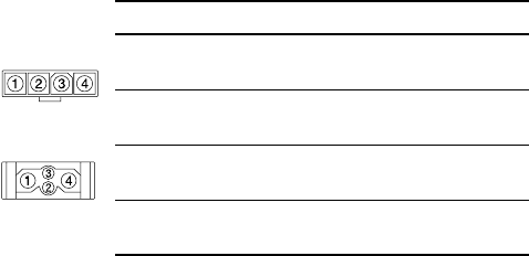
Power connector
The following table explains the pin allocations for the power
connectors on both 25W and 40W/50W radios.
Battery supply voltage
This radio is designed to operate from a nominal 12V negative
ground supply and may draw up to 8A of current (25W radios)
or 15A of current (40W/50W radios). The radio will tolerate a
supply voltage range of 10.8V to 16.0V at the radio.
Caution: In vehicles with a supply voltage greater than
16.0V, such as many trucks, it is essential to
provide a suitably rated DC to DC converter. This
will isolate the radio from excessive battery voltage
and provide the correct DC operating conditions.
Connecting the power cable
Caution: Disconnecting the vehicle’s battery may cause
problems with some electronic equipment, such as
vehicle alarms, engine management systems and
in-car entertainment systems. Check that the
Pin Signal name Description
1 AGND earth return for radio body
power source
2 SPK– external speaker output
3 SPK+ external speaker output
4 13V8_BATT DC power input for radio body
and control head
rear view
25W radio
40W/50W radio
rear view
52 Radio Installation
vehicle owner has the necessary information to
make all electronic equipment function correctly
after battery reconnection.
Caution: If the battery is not disconnected, exercise extreme
caution throughout the installation and install the
fuses only when the installation is ready to be
checked (see “Checking the installation” on
page 54).
1Disconnect the vehicle’s battery, unless specifically
prohibited from doing so by the customer, vehicle manu-
facturer, agent or supplier.
2Run the power cable between the radio’s mounting posi-
tion and the vehicle battery.
Caution:
The power cable should be protected from engine
heat, sharp edges and from being pinched or crushed.
3Cut the power cable to length, allowing about 20cm
(8 inches) excess at the radio end.
4Cut the negative and the positive wires where the in-line
fuse holders will be placed (as close to the battery
as possible).
Caution: Do not install the fuses until the installation is
ready to be checked.
5Insert each end of the negative wire into one of the in-
line fuse holders and crimp them to force the metal
contacts onto the wires.
6Connect the negative wire to the battery ground.
7Repeat step 5 for the positive wire and connect it to the
positive terminal of the battery.
Radio Installation 53
Mounting the U-bracket
The U-bracket can be used to install the radio on the dash-
board or on any sufficiently flat surface, using the self-drilling
screws and washers provided in the installation kit.
Caution: When mounting the radio, check whether the
mounting surface needs to be reinforced.
Caution: The U-bracket must be installed using at least
four screws.
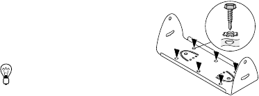
1If the U-bracket is being mounted over a curved surface,
bend the U-bracket tabs slightly, to match the
surface shape.
2Drill any holes required for cables and install suitable
grommets or bushings in the holes.
Caution: Check that the U-bracket is not distorted when the
screws are tightened.
3Screw the U-bracket in the
chosen mounting position using
the self-drilling screws and
washers provided.
Tip: For more precise
positioning, predrill
3 mm (1/8 inch) pilot holes for
the self-drilling screws. Reduce the hole size in metal that
is less than 1mm (1/32 inch) thick.
54 Radio Installation
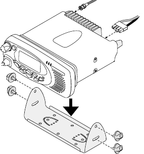
Installing the radio in the U-bracket
1Connect the antenna and power cables to the rear of
the radio.
2Position the radio in the U-bracket so that the holes in the
U-bracket line up with the holes in the radio chassis.
3Screw the radio into position using the four thumb screws
but without fully tightening the screws.
4Position the radio in the U-bracket for best viewing angle,
then tighten the thumb screws.
Checking the installation
1Insert the fuses into the power leads.
2Switch on the radio to confirm that it is operational.
Caution: Do not transmit yet.
3Connect an in-line power meter between the radio and
the antenna.
Radio Installation 55
4Transmit and measure the forward and reflected
power levels.
Less than 4% of the forward power should be reflected. If
this is not achieved, check the installation, including the
antenna length.
5Radios with a user interface only:
Once the reflected power levels are within tolerance,
make a call to another party on the radio (see “Making a
call” on page 30).
Other installation options
Contact your radio provider for further information.
56 Tait general software licence agreement
Tait general software licence agreement
This legal document is an Agreement between you (the
“Licensee”) and Tait Electronics Limited (“Tait”). By using
any of the Software or Firmware items prior-installed in
the related Tait product, included on this CD or down-
loaded from the Tait website, (hereinafter referred to as
“the Software or Firmware”) you agree to be bound by
the terms of this Agreement. If you do not agree to the
terms of this Agreement, do not install and use any of the
Software or Firmware. If you install and use any of the
Software or Firmware that will be deemed to be accept-
ance of the terms of this licence agreement.
The terms of this agreement shall apply subject only to
any express written terms of agreement to the contrary
between Tait and the Licensee.
Licence
TAIT GRANTS TO YOU AS LICENSEE THE NON-EXCLUSIVE RIGHT TO USE
THE SOFTWARE OR FIRMWARE ON A SINGLE MACHINE PROVIDED YOU
MAY ONLY:
1COPY THE SOFTWARE OR FIRMWARE INTO ANY MACHINE READABLE
OR PRINTED FORM FOR BACKUP PURPOSES IN SUPPORT OF YOUR
USE OF THE PROGRAM ON THE SINGLE MACHINE (CERTAIN
PROGRAMS, HOWEVER, MAY INCLUDE MECHANISMS TO LIMIT OR
INHIBIT COPYING, THEY ARE MARKED “COPY PROTECTED”),
PROVIDED THE COPYRIGHT NOTICE MUST BE REPRODUCED AND
INCLUDED ON ANY SUCH COPY OF THE SOFTWARE OR FIRMWARE;
AND / OR
2MERGE IT INTO ANOTHER PROGRAM FOR YOUR USE ON THE SINGLE
MACHINE (ANY PORTION OF ANY SOFTWARE OR FIRMWARE MERGED
INTO ANOTHER PROGRAM WILL CONTINUE TO BE SUBJECT TO THE
TERMS AND CONDITIONS OF THIS AGREEMENT).
THE LICENSEE MAY NOT DUPLICATE, MODIFY, REVERSE COMPILE OR
REVERSE ASSEMBLE ANY SOFTWARE OR FIRMWARE IN WHOLE OR PART.
Title to Software
THIS AGREEMENT DOES NOT CONSTITUTE A CONTRACT OF SALE IN RELA-
TION TO THE SOFTWARE OR FIRMWARE SUPPLIED TO THE LICENSEE. NOT
WITHSTANDING THE LICENSEE MAY OWN THE MAGNETIC OR OTHER
PHYSICAL MEDIA ON WHICH THE SOFTWARE OR FIRMWARE WAS ORIGI-
NALLY SUPPLIED, OR HAS SUBSEQUENTLY BEEN RECORDED OR FIXED, IT
IS A FUNDAMENTAL TERM OF THIS AGREEMENT THAT AT ALL TIMES TITLE
AND OWNERSHIP OF THE SOFTWARE OR FIRMWARE, WHETHER ON THE
ORIGINAL MEDIA OR OTHERWISE, SHALL REMAIN VESTED IN TAIT OR
THIRD PARTIES WHO HAVE GRANTED LICENCES TO TAIT.
Term and Termination
THIS LICENCE SHALL BE EFFECTIVE UNTIL TERMINATED IN ACCORDANCE
WITH THE PROVISIONS OF THIS AGREEMENT. THE LICENSEE MAY TERMI-
NATE THIS LICENCE AT ANY TIME BY DESTROYING ALL COPIES OF THE
SOFTWARE OR FIRMWARE AND ASSOCIATED WRITTEN MATERIALS. THIS
LICENCE WILL BE TERMINATED AUTOMATICALLY AND WITHOUT NOTICE
FROM TAIT IN THE EVENT THAT THE LICENSEE FAILS TO COMPLY WITH
ANY TERM OR CONDITION OF THIS AGREEMENT. THE LICENSEE AGREES
TO DESTROY ALL COPIES OF THE SOFTWARE OR FIRMWARE AND ASSO-
CIATED WRITTEN MATERIALS IN THE EVENT OF SUCH TERMINATION.
Limited Warranty
THE SOFTWARE OR FIRMWARE IS SUPPLIED BY TAIT AND ACCEPTED BY
THE LICENSEE “AS IS” WITHOUT WARRANTY OF ANY KIND EITHER
EXPRESSED OR IMPLIED, INCLUDING BUT NOT BEING LIMITED TO ANY
IMPLIED WARRANTIES AS TO MERCHANTABILITY OR FITNESS FOR ANY
PARTICULAR PURPOSE. THE LICENSEE ACKNOWLEDGES THAT THE SOFT-
WARE OR FIRMWARE IS USED BY IT IN BUSINESS AND ACCORDINGLY TO
THE MAXIMUM EXTENT PERMITTED BY LAW NO TERMS OR WARRAN-
TIES WHICH ARE IMPLIED BY LEGISLATION SHALL APPLY TO THIS AGREE-
MENT. TAIT DOES NOT WARRANT THAT THE FUNCTIONS CONTAINED IN
THE SOFTWARE OR FIRMWARE WILL MEET THE LICENSEE’S REQUIRE-
MENTS OR THAT THE OPERATION OF THE SOFTWARE OR FIRMWARE
WILL BE UNINTERRUPTED OR ERROR FREE.
Exclusion of Liability
TAIT’S ENTIRE LIABILITY AND THE LICENSEE’S EXCLUSIVE REMEDY SHALL
BE THE FOLLOWING:
1IN NO CIRCUMSTANCES SHALL TAIT BE UNDER ANY LIABILITY TO THE
LICENSEE, OR ANY OTHER PERSON WHATSOEVER, FOR ANY DIRECT OR
CONSEQUENTIAL DAMAGE ARISING OUT OF OR IN CONNECTION WITH
ANY USE OR INABILITY OF USING THE SOFTWARE OR FIRMWARE.
2TAIT WARRANTS THE OPERATION OF THE SOFTWARE OR FIRMWARE
ONLY WITH THE OPERATING SYSTEM FOR WHICH IT WAS DESIGNED.
USE OF THE SOFTWARE OR FIRMWARE WITH AN OPERATING SYSTEM
OTHER THAN THAT FOR WHICH IT WAS DESIGNED MAY NOT BE
SUPPORTED BY TAIT, UNLESS OTHERWISE EXPRESSLY AGREED BY TAIT.
General
THE LICENSEE CONFIRMS THAT IT SHALL COMPLY WITH THE PROVISIONS
OF LAW IN RELATION TO THE SOFTWARE OR FIRMWARE.
Law and Jurisdiction
THIS AGREEMENT SHALL BE SUBJECT TO AND CONSTRUED IN ACCORD-
ANCE WITH NEW ZEALAND LAW AND DISPUTES BETWEEN THE PARTIES
CONCERNING THE PROVISIONS HEREOF SHALL BE DETERMINED BY THE
NEW ZEALAND COURTS OF LAW. PROVIDED HOWEVER TAIT MAY AT ITS
ELECTION BRING PROCEEDINGS FOR BREACH OF THE TERMS HEREOF OR
FOR THE ENFORCEMENT OF ANY JUDGEMENT IN RELATION TO A
BREACH OF THE TERMS HEREOF IN ANY JURISDICTION TAIT CONSIDERS
FIT FOR THE PURPOSE OF ENSURING COMPLIANCE WITH THE TERMS
HEREOF OR OBTAINING RELIEF FOR BREACH OF THE TERMS HEREOF.
No Dealings
THE LICENSEE MAY NOT SUBLICENSE, ASSIGN OR TRANSFER THE LICENCE
OR THE PROGRAM EXCEPT AS EXPRESSLY PROVIDED IN THIS AGREE-
MENT. ANY ATTEMPT OTHERWISE TO SUBLICENSE, ASSIGN OR TRANSFER
ANY OF THE RIGHTS, DUTIES OR OBLIGATIONS HEREUNDER IS VOID.
No Other Terms
THE LICENSEE ACKNOWLEDGES THAT IT HAS READ THIS AGREEMENT,
UNDERSTANDS IT AND AGREES TO BE BOUND BY ITS TERMS AND CONDI-
TIONS. THE LICENSEE FURTHER AGREES THAT SUBJECT ONLY TO ANY
EXPRESS WRITTEN TERMS OF AGREEMENT TO THE CONTRARY BETWEEN
TAIT AND THE LICENSEE THIS IS THE COMPLETE AND EXCLUSIVE STATEMENT
OF THE AGREEMENT BETWEEN IT AND TAIT IN RELATION TO THE SOFTWARE
OR FIRMWARE WHICH SUPERSEDES ANY PROPOSAL OR PRIOR AGREEMENT,
ORAL OR WRITTEN AND ANY OTHER COMMUNICATIONS BETWEEN THE
LICENSEE AND TAIT RELATING TO THE SOFTWARE OR FIRMWARE