TandD RTR50 Wireless Communication Port User Manual
TandD Corporation Wireless Communication Port
TandD >
Contents
- 1. Users Manual
- 2. Users Manual Supplement
Users Manual

2006.12 16004474030
#OMMUNICATION0ORT
7IRELESS
242
© Copyright 2006 T&D Corporation. All rights reserved.
i
Notices
Carefully read this manual so that you can properly use this product.
T&D Corporation accepts no responsibility for any malfunction of and / or
trouble with this product or with your computer that is caused by the
improper handling of this product and will deem such trouble or
malfunction as falling outside the conditions for free repair of the attached
warranty.
ȆAll rights of this User's Manual belong to T&D Corporation. It is prohibited to use,
duplicate and / or arrange a part or whole of this User's Manual without the
permission of T&D Corporation.
ȆMicrosoft® and Windows® are registered trademarks of Microsoft Corporation USA
and are binding in the USA and all other countries.
ȆCompany names and product names are trademarks or registered trademarks of
each company.
ȆSpecifi cations, design and other contents are subject to change without notice.
ȆOn screen messages in this manual may vary slightly from the actual messages.
ȆPlease notify the shop where you purchased this product or T&D Corporation of
any mistakes, errors or unclear explanations in this manual. T&D Corporation
accepts no responsibility for any damage or loss of income caused by the use of
our product.
ȆThis product has been designed for private or industrial use only. It is not for use in
situations where strict safety precautions are necessary such as in connection with
medical equipment, whether directly or indirectly.
ȆWe are not responsible for any malfunction or trouble caused by the use of our
product or by any problem caused by the use of measurement results of our unit.
Please be fully aware of this before using our product.
ȆSome of our products, which come under the category of strategic goods in foreign
trade law, need the permission of the Japanese government to be exported outside
of Japan.
ȆThe Manual itself can be downloaded from our Home Page: http://www.tandd.com

ii
Introduction
Software User Agreement
Escape Clauses
ȆT&D Corporation does not guarantee the operation of RTR-50 for Windows®.
ȆT&D Corporation shall not accept any responsibility for any damage, whether direct or
indirect, that results from the usage of T&D Recorder for Windows.
ȆSpecifi cations of RTR-50 for Windows® may be subject to change and service may be
terminated without advance notice to the user. In such a case, T&D Corporation shall
not be responsible for any damages, whether direct or indirect, from the inability to
use RTR-50 for Windows®.
ȆT&D Corporation has no obligation to correct any defects found in RTR-50 for
Windows.
Copyright
ȆThe Copyright for RTR-50 for Windows®, including the program and relevant
documents, belongs solely to T&D Corporation.
ȆThe reprinting or redistribution for commercial purposes whether in part or in whole, in
magazines or as a part of any product is strictly forbidden without the expressed
consent of T&D Corporation. Any inquires concerning commercial redistribution
should be directed to the Sales Department of T&D Corporation.
ȆPlease do not attempt to make any changes or modifi cations to RTR-50 for Windows®.

iii
Table of Contents
Software User Agreement ------------------- ii
Escape Clauses ----------------------------------ii
Copyright ------------------------------------------- ii
Safety Precautions and Instructions ------ v
To ensure safety be sure to obey all of the
following warnings. -------------------------------v
1. Introduction
What is Wireless COMMUNICATION PORT
RTR-50? -----------------------------------------3
Application Examples ---------------------------3
What is RTR-50 for Windows®? ------------4
Outline ----------------------------------------------4
Basic Functions ----------------------------------4
Package Contents -----------------------------6
Part Names and Functions ------------------7
Appearance Diagram ---------------------------7
2.Getting Ready
General Procedure ----------------------------9
Getting Ready --------------------------------10
Install Batteries --------------------------------- 10
Install RTR-50 for Windows® --------------11
Connect the RTR-50 with a USB
communication cable to your computer 12
Installing the USB Device Driver --------- 13
Confi rming the USB Device Driver
Connection to the Computer -------------- 18
Windows® XP / 2000 --------------------------18
Windows® Me/98SE ---------------------------19
If USB Device Driver Installation Fails -- 20
How to Re-install -------------------------------20
Connecting the RTR-50 with a serial
communication cable to your computer 21
Setting up the Communication Port ----- 22
3.How to useȨRTR-50 for Windowsȩ
Basic Functions ------------------------------25
Open ȨRTR-50 for Windowsȩ ------------25
Explanation of Display ------------------------25
Main Unit Info ----------------------------------- 27
Remote Unit / Relay Unit Registration -- 28
Basic Procedure for Registration ----------- 28
Registering a Remote Unit ------------------ 31
Deletion and Initialization of
Remote Units ------------------------------------ 33
Get Remote Unit Recording Settings
(Wireless Communication) ------------------- 35
Get Remote Unit Info
(Optical Communication) --------------------- 37
Registering a Relay Unit ---------------------38
Connect a Remote Unit via Relay Unit(s) 39
Deletion and Initialization of Relay Units -41
ಎࠑܥેఠ৾ංȪྫȫ ----------------43
ܥ /ಎࠑܥૂ༭৾ංȪೄ୪ȫ -------- 44
ྫΞΑΠ ---------------------------------45
ݟ̞ષ̬୭ --------------------------------- 47
[મळ୭ ]δΗϋ ----------------------------- 49
ܱٳই୭ --------------------------------- 50
ྫ͈ાࣣ ---------------------------------50
͈ાࣣ ------------------------------------51
κΣΗςϋΈ /࠙༭۬ণ୭ ------------- 55
[κΣΗςϋΈ୭ ] --------------------------55
[κΣΗςϋΈۼڞ୭ ]δΗϋ ----------- 55
[࠙༭୭ ] ------------------------------------ 56
[࠙༭ιȜσ୭ ]δΗϋ -------------------- 56
[࠙༭υΈນা ]δΗϋ ----------------------- 56
[κΣΗςϋΈȆ࠙༭۬ণٳই ]δΗϋ -- 57
κΣΗςϋΈΈρέْ࿂ ---------------------57
κΣΗςϋΈΈρέ୭ ---------------------58
ιȜσ୭ ---------------------------------------61
ু൲ਓਬ୭ --------------------------------- 63
[ু൲ਓਬ୭ ] --------------------------------- 63
[ু൲ਓਬٳই ]δΗϋ ----------------------- 63
[ΟȜΗ༗ంέσΘ ]δΗϋ -------------- 64
[ু൲ਓਬυΈນা ]δΗϋ ----------------- 64

iv
Getting Ready RTR-50 for Windows Graph Others
Introduction
4.Graph Operation
Temperature / Humidity Graph ----------- 68
Display Names and Functions --------------68
Zooming In and Out on the Graph ---------70
Data List Display ------------------------------- 70
Editing the Graph ---------------------------- 72
Changing Graph Display Colors ------------ 72
Selected Channels ON/OFF ----------------72
Set High, Low, Average
Calculation Range ----------------------------- 72
Edit Recording Conditions -------------------73
Re-order Channel Data ----------------------- 74
Erase Selected Channel Data -------------- 75
Shift Unit (Ɏ/ ȌF) ------------------------------------- 75
Change Graph Colors ------------------------- 75
Copy Display to Clipboard -------------------77
Graph ---------------------------------------------77
Multi-scale Graph ---------------------------- 78
Display Names and Functions --------------78
Zooming In and Out on the Graph ---------80
Data List Display ------------------------------- 81
Selected Channels ON/OFF ----------------82
Scale Display ON/OFF -----------------------82
Set High, Low, Average
Calculation Range ----------------------------- 83
Edit Recording Conditions -------------------84
Re-order Channel Data ----------------------- 85
Merge Channel Data --------------------------86
Erase Selected Channel Data -------------- 86
Vertical Axis Range Display Settings ----- 87
Scale and Unit Conversion ------------------ 89
Change Graph Colors ------------------------- 90
Event Viewer ---------------------------------- 91
Display Names and Functions --------------91
Shift Display -------------------------------------92
Shift Ascending / Descending -------------- 92
Event Viewer ---------------------------------- 93
View File Info about data in the currently
displayed data list. -----------------------------93
Event Viewer ---------------------------------- 94
Saving a File ---------------------------------- 95
3 Ways to Save Files -------------------------- 95
Saving Event Viewer Data -------------------96
Saving Data in Text File -------------------- 97
When saving Temp/Humid Graph and
Multi-scale Graph data as Text File -------- 97
When saving Event Viewer data as
Text File ------------------------------------------- 98
Opening a File with the Temp/Humid
Graph and Multi-scale Graph --------------- 99
Opening a File with the Event Viewer --- 100
Others
Troubleshooting ---------------------------- 103
How to check ---------------------------------- 103
For product information or questions
contact us at: -------------------------------- 110
Wireless Communication RTR-50
Warrant -------------------------------------- 111
v
ŔŢŧŦŵźġőųŦŤŢŶŵŪŰůŴġŢůťġŊůŴŵųŶŤŵŪŰůŴ
To ensure safety be sure to obey all of the following warnings.
The following items should be strictly obeyed for the safe usage of this unit, and for
protecting yourself and other people from bodily harm and / or damage to property. To
ensure the proper use of our product, please read the following carefully and fully
understand the contents.
Explanation of Symbols
Explanation of Warning Symbols
DANGER
These entries are actions that absolutely under no
circumstance should be taken. The taking of such
an action may cause serious personal physical
damage or death.
CAUTION These entries are actions that if taken may lead to
physical injury or damage to persons or things.
Explanation of Picture Symbols
Denotes an important warning or caution.
Denotes a forbidden action. Inside or near the symbol will
appear another symbol giving details.
ȪEXȇstands for DO NOT TAKE APARTȫ
Denotes an action that you must take.
vi
Introduction
DANGERS
Do not take apart, repair or modify the main unit.
Doing so may cause fi re or electrocution.
Do not use this unit in wet or humid places, such as a bathroom.
If any smoke or strage smells are emitted from the unit,
immediately remove the batteries and stop using.
Continued use may cause fi re or electrocution.

vii
CAUTION
This unit is not water-resistant.
If the unit gets dirty, wipe it with a clean cloth and a mild detergent.
Please do not insert your fi ngers or any foreign objects into any of the
devices' jacks.
Battery terminals may provide insuffi cient contact due to age or
vibration.
This may lead to data loss.
Do not use any other batteries than those that are specifi ed in this User's
Manual.
It may cause a fi re or other trouble including malfunction.
Do not use or store the Thermo Recorder in any of the following
places. Doing so may cause electrocution, fi re and / or other
adverse effects to the device and / or your computer.
- Areas exposed to direct sunlight
This will cause the inside of the device to become overheated and may
cause fi re, deformation, and / or other damage including malfunction.
- Areas prone to strong magnetic fi elds
This may cause damage including malfunction.
- Areas exposed to water leakage
This may cause electrocution or other damage incluing malfunction.
- Areas exposed to excessive vibration
This may cause injury, malfunction, damage or loss of proper electrical
contact.
- Areas near fi re or exposed to excessive heat
This may cause damage including malfunction and deformation.
- Areas prone to smoke, duct and dirt
This may cause damage including malfunction.

viii
Introduction
Wireless Regulations
Radio, EMC and Safety Regulations
This device complies with part 15 of the Federal Communications
Commision (FCC) rules and with RSS-210 of the Industry Canada (IC).
Operation is subject to the following conditions:
(1) This device may not cause harmful interference, and
(2) This device must accept any interference received, including
interference that may cause undesired operation.
NOTE:
This equipment has been tested and found to comply with the limits for a Class A digital
device, pursuant to part 15 of the FCC Rules. These limits are designed to provide
reasonable protection against harmful interference when the equipment is operated in a
commercial environment. This equipment generates, uses, and can radiate radio
frequency energy and, if not installed and used in accordance with the instruction manual,
may cause harmful interference to radio commuications. Operation of this equipment in a
residetial area is likely to cause harmful interference in which case the user will be
required to correct the interference at his own expense.
1

2
1. Introduction
3
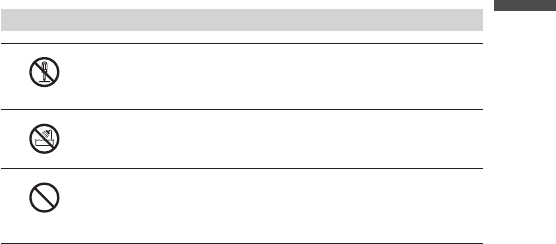
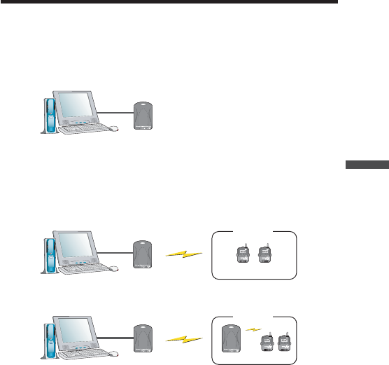
What is Wireless COMMUNICATION PORT RTR-50?
The Wireless COMMUNICATION PORT RTR-50 is a base unit designed to carry out
wireless communication with our compact waterproof Wireless Data Loggers, RTR-5
Series (RTR-51/52/53/RVR-52) and to be connected to a computer via a USB or serial
communication cable to gather data from and control the loggers.Also, by setting up an
RTR-50 between the RTR-50 designated as the Base Unit and the RTR-5 Series Remote
Data Logger unit, you can use any RTR-50 as a Relay Unit for wireless communication.
53"#ABLE
3ERIAL#ABLE
RTR-50 PC
!!
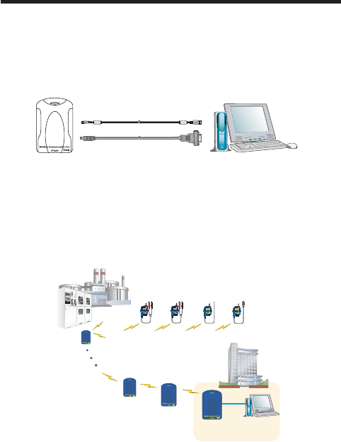
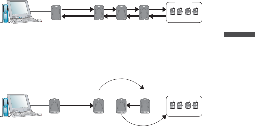
Application Examples
- For the gathering of recorded data via wireless communication from long distances
and the controlling of data loggers in places where handling of data loggers is diffi cult
or impossible
- For downloading recorded data and monitoring current readings from moving or
rotating data loggers on production lines
/FFICE
œŕœĮĶij
2EMOTE5NIT 2EMOTE5NIT 2EMOTE5NIT 2EMOTE5NIT
œŗœĮĶij œŗœĮĶij œŕœĮĶˏ
"ASE5NIT
242
53"
2ELAY5NIT
242
2ELAY5NIT
242
* The communication range for each RTR-50 Relay Unit is up to 100m.

4
Introduction
What is RTR-50 for Windows®?
Outline
The easy-to-use software, RTR-50 for Windows® offers a variety of useful functions for any
RTR-5 series data logger: including control of data logger recording settings, data
downloading, graph display, table creation, printing, and fi le output.
Using our exclusive short-wave wireless technology it is possible to carry out Remote Unit
Registrations and make Operational Settings between an RTR-50 Base and any RTR-5
Series Data Logger via wireless communication. If you wish to use an RTR-50 as a Relay
Unit, it is also possible to carry out Relay Unit Registration and make other Operational
Settings.
Basic Functions
Wireless Communication
Start Recording / Download Data / Monitor Current Readings / Warning Alarm /
Auto-Download / Get Remote Unit Status / Wireless Communication Test / Get Radio
Wave Strength of Relay Unit / Get Remaining Battery Life in Relay Unit
Optical Communication---Carried out by placing a data logger (Remote
Unit) face down on an RTR-50 (Base Unit).
Remote Unit Registration and/or Initialization / Start Recording / Download Data / Get
Remote Unit Info
Direct Cable Communication---Communication carried out via cable
between the computer and the Base Unit / Relay Unit(s) for the initial
settings.
Relay Unit Registration and/or Initialization (Returning RTR-50 to Base Unit) / Relay
Route Name Settings/ Communication Frequency Channel Settings / Get Remaining
Battery Life
5
Data Operation
-Easy processing of the data downloaded from a Remote Unit into graphs, saving to
fi les and/or printing.
-Convert the Remote / Relay Unit Registration Info to fi le format.
-Display current measurements in graph formȂWarning Status Log
-The downloading of data can be set to be automatically carried out at a specifi ed time
or at a set interval of time.
Others
-Monitoring at each location for warnings is carried out and if any of the gathered data
exceeds the set limit, a notifi cation can be sent via e-mail.
To properly use this software, the following operational environment
is necessary.
Compatible OS Microsoft Windows® 98SE/Me (English)
Microsoft Windows® XP/2000 (English)
Software Microsoft Internet Explorer ver.5.01 or higher
PC / CPU IBM Compatible equipped with more than Pentium
90MHz or NEC 98 Series
USB Communication or Serial CommunicationȪRS232-C
D-sub 9pinȫ
Operating Environment A Stable Windows® Operating Environment
6
Introduction
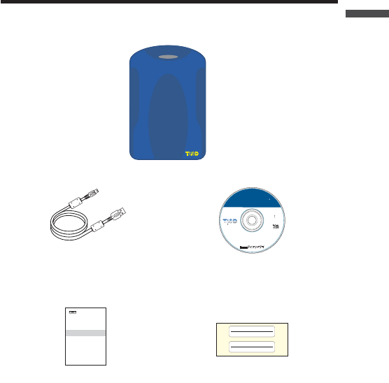
Package Contents
The following items are included in the package:
Wireless Communication Port
RTR-50
RTR-50
MS-Windows 2000/Xp
MS-Windows 98SE/Me
FOR242242262
Copyright 1995-2006 TandD
Corporation. All rights reserved.
6ER
242FOR7INDOWS
USB cable x 1 Software
CD-ROM
©#OPYRIGHT4$#ORPORATION!LLRIGHTSRESERVED
#OMMUNICATION0ORT
7IRELESS
242
Manual x 1 Name Seal*1
7
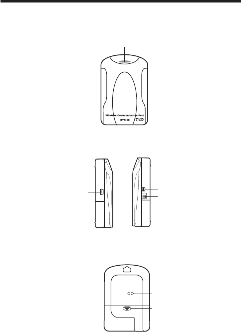
Part Names and Functions
Appearance Diagram
-ONITOR,%$
[Front]
!#!DAPTORCONNECTIONJACK
3ERIAL-INI㧕
53"-INI"㧕
[Left Side / Right Side]
[Rear]
"ATTERY#OVER
/PTICAL
#OMMUNICATION0ORT

8
2.Getting Ready
This section provides instructions on getting the RTR-50 ready to use.

9
General Procedure
1.
RTR-50 for Win ͬͼϋΑΠȜσ
3.
RTR-50 ུఘͬΩΕϋͅ୪̳ͥȃ
Ώςͺσ࣐̠ͬાࣣ͉Ȃমஜͅഩ౻̹͉͘
AC ͺΘίΗͬΓΛΠ̳ͥ
2.
RTR-50 ུఘͬȂUSB ̹͉͘ΏςͺσεȜΠͅ୪̳ͥȃ
USB ΉȜήσঀဥশ ----------------
USB ΡρͼΨ͈ͼϋΑΠȜσ /
εȜΠ͈୭
ΏςͺσΉȜήσঀဥশ ----------- εȜΠ͈୭
4.
RTR-50 for Win ́ঊܥ /ಎࠑܥ͈ഴȃͥ͢ͅڎਅ୭
5.
ঊܥ /ಎࠑܥ͈୭౾
6.
RTR-50 for Win ́Ȃྫͥ͢ͅڎਅ୭
7.
ΟȜΗ৾ංࢃȂڎΈρέ̀ͅΟȜΗۯၑ /ௌै൝
P.10 ∼
P. 11
P.10 ∼
P. 2 8 ∼
P. 2 8 ∼
P. 4 6 ∼
P. 6 7 ∼
10
Getting Ready
Getting Ready
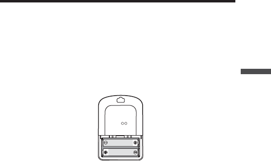
Install Batteries
For serial communication with your computer and to use as a Relay Unit, make sure to
install batteries.
NOTE:
When the RTR-50 is connected by USB cable to your computer, there is no need to
insert batteries.
Insert 2 AA alkaline batteries as shown in the fi gure.
NOTE:
- Always use two batteries of the same type.
- Make sure not to mistake + / -.
- A battery cannot be charged inside the RTR-50.
*The LED lamp will blink once when usable batteries are installed.

11
Install RTR-50 for Windows®
- Is Windows® operating properly ȉ
If Windows® is not operating properly, RTR-50 for Windows® may not be
installed correctly or it may not operate properly.
- Please quit all other applications.
If you are running other applications, make sure to quit them before
installation.If you have any permanently active software, such as a virus
check or scan program in your computer, make sure to also quit it.
1.
Open Windows®.
2.
Insert the attached CD-ROM in the CR-ROM drive.
In a few seconds, the [Install Program] window will appear.
*If that window does not automatically open, please, please open it by double
clicking the CD-ROM icon in [My Computer] on your desktop.
3.
Select [RTR-50 for Windows®] and click the [Execute] button to start the
installation.
4.
Continue the installation by following the directions as they appear.
After installation has been completed, "RTR-50 for Windows®" will be
registered in Windows' [Start] Menu.
When connecting the RTR-50 to your computer for direct communication
to download or make setting changes, etcȤ, please use the USB
communication cable (provided) or the optional serial communication
cable (TR-07C).
12
Getting Ready
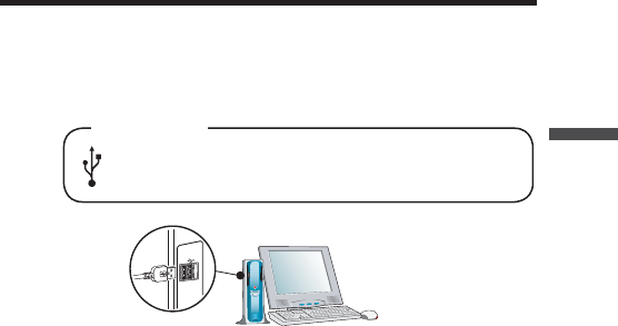
Connect the RTR-50 with a USB
communication cable to your computer
1.
Connect the RTR-50 with the provided USB communication cable (US-15C) to
your computer.
*It is not possible to simultaneously use both RTR-57U and RTR-50.
USB Port Mark
*
Make sure that the USB cable is inserted fully, so as not to cause an
improper connection.
2.
Install the USB Device Driver
* For details about the driver installation, see the next section.
13
Installing the USB Device Driver
You will need to install this driver in order to use the device with a USB cable and Windows.
The USB device driver must be installed for communication via USB between your
computer and an RTR-50.After installing the USB device driver, your computer will be able
to detect and recognize RTR-50 devices that have been connected with a USB cable.
For Windows® XP
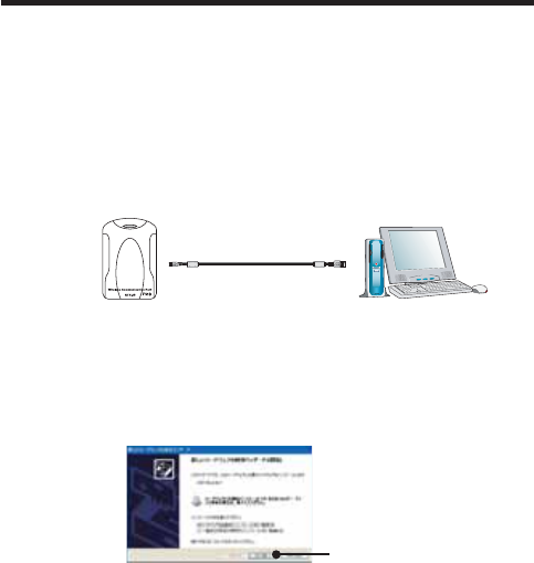
1.
Turn on your computer and open Windows. After Windows has been completely
started up, connect the supplied USB cable to a USB port on the RTR-50 and
your computer.
53"#ABLE
53"MINI"0LUG 53"MINI!0LUG
To RTR-50 To PC
RTR-50
2.
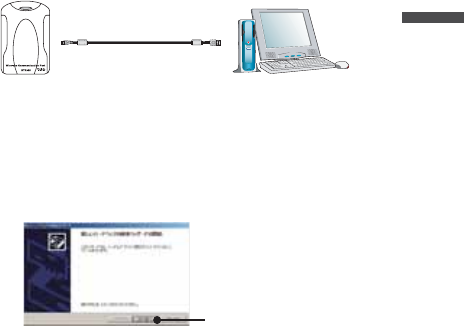
Insert the attached CD-ROM in the CR-ROM drive.If the Installation Window
opens, close it.
3.
By connecting an RTR-50 unit to the USB cable already connected to your
computer, the [Found New Hardware Wizard ] will automatically open.
4.
By checking [Install the software automatically (Recommended)] and clicking
[Next], the software will automatically be installed.
[Next]button
5.
After completing installation, click the [Finish] button
Confi rm the Connections (see p.18).
If the Driver is not automatically detected
Please search by specifying the place as Ȩ[Device Driver \ RTR-50] in
the CD-ROM driveȩ and install manually from there.
14
Getting Ready
For Windows® 2000
1.
Turn on your computer and open Windows. After Windows has been completely
started up, connect the supplied USB cable to a USB port on the RTR-50 and
your computer.
53"#ABLE
53"MINI"0LUG 53"MINI!0LUG
To RTR-50 To PC
RTR-50
2.
Insert the attached CD-ROM in the CR-ROM drive.If the Installation Window
opens, close it.
3.
By connecting an RTR-50 unit to the USB cable already connected to your
computer, the [Found New Hardware Wizard ] will automatically open.
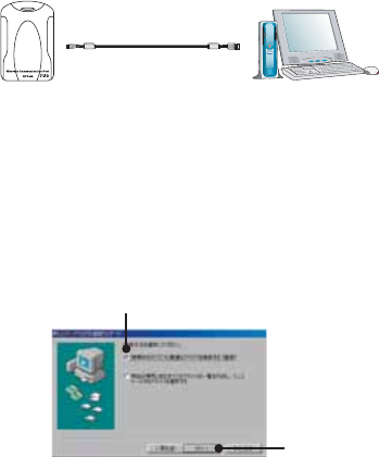
4.
By clicking the [Next] button, a window will open where you can choose how you
wish to fi nd the driver fi le.
[Next]button
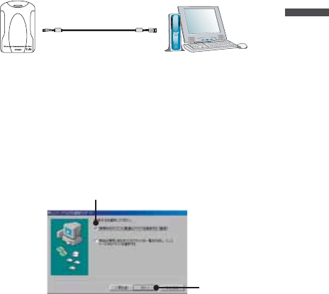
5.
Check [Search for a suitable driver for my device (Recommended )] and click
the [Next] button.
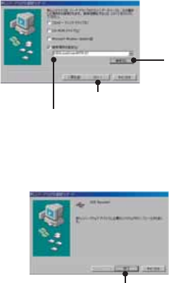
6.
Check [CD-ROM drive] and then click the [Next] button.
7.
Click [Next] to start the installation.
8.
After completing installation, click the [Finish] button
Confi rm the Connections (see p.18).
If the Driver is not automatically detected
Please search by specifying the place as Ȩ[Device Driver\ RTR-50] in
the CD-ROM driveȩ and install manually from there.
15
For Windows® Me
1.
Turn on your computer and open Windows. After Windows has been completely
started up, connect the supplied USB cable to a USB port on the RTR-50 and
your computer.
53"#ABLE
53"MINI"0LUG 53"MINI!0LUG
To RTR-50 To PC
RTR-50
2.
Insert the attached CD-ROM in the CR-ROM drive.If the Installation Window
opens, close it.
3.
By connecting an RTR-50 unit to the USB cable already connected to your
computer, the [Add New Hardware Wizard ] will automatically open.
4.
By clicking the [Next] button, a window will open where you can choose how you
wish to fi nd the driver fi le.
5.
Check [Automatic search for a better driver (Recommended )] and click the [Next]
button.
Check
[Next]button
If the Driver is not automatically detected
Please search by specifying the place as Ȩ[Device Driver\ RTR-50] in
the CD-ROM drive and install manually from there.
16
Getting Ready
For Windows® 98SE
1.
Turn on your computer and open Windows. After Windows has been completely
started up, connect the supplied USB cable to a USB port on the RTR-50 and
your computer.
53"#ABLE
53"MINI"0LUG 53"MINI!0LUG
To RTR-50 To PC
RTR-50
2.
Insert the attached CD-ROM in the CR-ROM drive.If the Installation Window
opens, close it.
3.
By connecting an RTR-50 unit to the USB cable already connected to your
computer, the [Add New Hardware Wizard ] will automatically open.
4.
By clicking the [Next] button, a window will open where you can choose how you
wish to fi nd the driver fi le.
5.
Check [Search for the best driver for your device (Recommended )] and click the
[Next] button.
check
[Next]button
17
6.
Place a check next to [Specify a location] and click the [Browse] button. Select
Ȩ[Device Driver\RTR-50] in the CD-ROM driveȩ and click [Next].
Select Ȩ[Device Driver\RTR-50] in the
CD-ROM driveȩ
[Next]button
[Browse]
button
7.
After completing installation, click the [Finish] button
Confi rm the Connections (see p.19).
[Finish]button
18
Getting Ready
Confi rming the USB Device Driver Connection
to the Computer
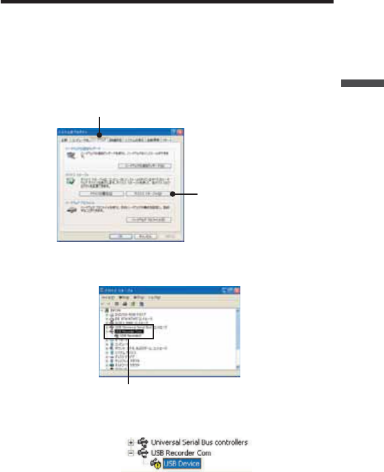
Windows® XP / 2000
1.
Open the [Control Panel] and double click on [System]; the [System Properties]
will be displayed.
2.
Click the [Hardware] Tab, and click the [Device Manager] button in the [Device
Manager] Area.
[Hardware] tab
Device Manager
3.
In the Device Manager Window, check to see if [USB Recorder 2] is listed under
[USB Recorder 2 COM].
USB Recorder2
NOTE:
If the following tree items appear, see the ȨIf USB Device Driver Installation Failsȩ
(p.20).
19
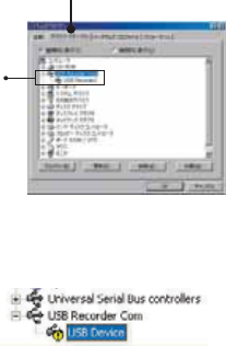
Windows® Me/98SE
1.
Open the [Control Panel] and double click on [System], the [System Properties]
will be displayed.
2.
In the Device Manager Window, check to see if [USB Recorder 2] is listed under
[USB Recorder 2 COM].
[Device Manager] tab
USB Recorder2
NOTE:
If the following tree items appear, see the ȨIf USB Device Driver Installation Failsȩ
(p.21).
20
Getting Ready
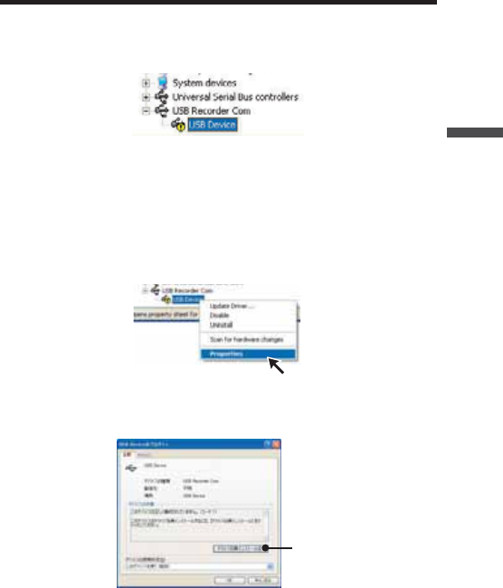
If USB Device Driver Installation Fails
If, during USB device driver installation, some trouble occurs that results in a failure to
install properly, the following display will appear in the Device Manager.
If this occurs, the USB device driver must be re-installed.Please follow the directions below
to carry out the operation.
How to Re-install
1.
In the Device Manager Window, right click on [USB Device] under [Other
Devices] and then click on [Properties] to display the [USB Device Properties]
Window.
2.
In the [USB Device Properties] Window, click on the [Re-install Driver] button to
display the Installation Window.Follow the directions to install.
[Re-install Driver] button
21
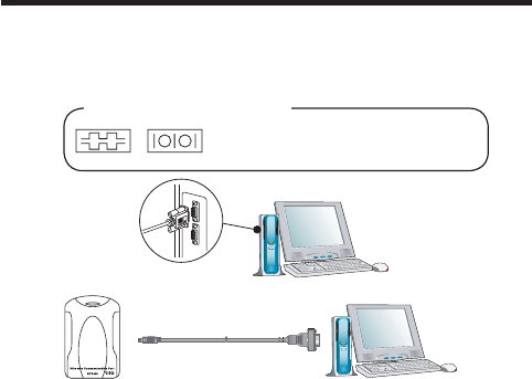
Connecting the RTR-50 with a serial
communication cable to your computer
1.
Connect to your computer using the optional serial communication cable
(TR-07C).
*It is not possible to simultaneously use both RTR-57U and RTR-50.
Examples of serial port marks
The connection cable is a D-SUB 9 pin
female jack that should be connected to the
place with such a marking.
To RTR-50 To PC
3ERIAL#ABLE
ȁȁȁȁ
NOTE:
- Make sure to connect it to the correct place to ensure communication.
- Make sure that the cable is inserted fully, so as not to cause an improper
connection.
-For Serial Communication make sure to insert 2 AA batteries or use the optional
AC Adaptor (AD-0601).
2.
Make Communication Port Settings.
For details about Communication Port Settings, see the next page.
22
Getting Ready
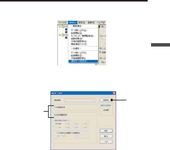
Setting up the Communication Port
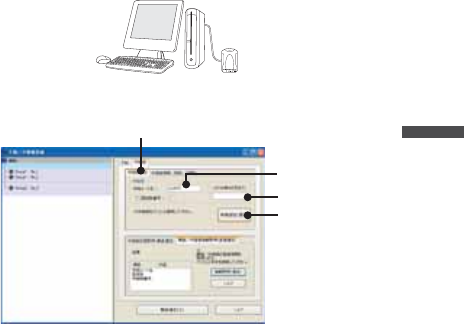
1.
From the [Communication] Menu, select [COM Port Settings].
2.
Place a check next to: [Serial Communication] when communicating via serial
communication cable, [USB Communication] when communicating via USB.
Then click the [Auto Detect] to automatically fi nd an RTR-50 using the currently
set communication method (USB or Serial).
[Auto Detect]
button
Check
3.
After the search, if the message ȨAn RTR-50 unit was detectedȩ appears in
the [Detection Results] box, settings have been successfully completed.
Click the [Close] button to close the Window.
NOTE:
- If the USB driver has not been properly installed, USB communication will not be
possible.
- If no port is detected, see [Troubleshooting] on pages 103.
23

24
3.How to useȨRTR-50 for Windowsȩ
This section guides you through how to use the software,
ȨRTR-50 for Windowsȩ, included with each RTR-50 unit
The software is designed to allow for easy data processing,
creation of Graphs and management of all settings
and registrations necessary to create Remote Units and Relay Units.
25
Basic Functions
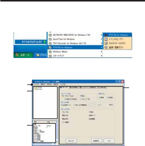
Open ȨRTR-50 for Windowsȩ
From the list of programs in the Windowȧs Start Menu, click on [RTR-50 for Windows] -
[RTR-50 for Windows] to open.
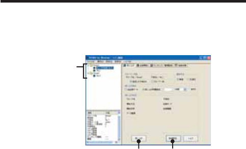
Explanation of Display
ȨRTR-50 for Windowsȩ Main Window
୭ςͺ
ঊܥ֚။
ঊܥίυΩΞͻ
Menu Bar

26
RTR-50 for Windows
Menu Bar
[File] Menu
Open Temp/Humidity Graph / Open Multi-scale Graph / Open Event Viewer / Open
Remote Registration File / Save as... / Quit
[Communication] Menu
Wireless Communication:
Download Data/ Start Recording / Monitoring / Warning Monitoring / Auto Download /
Get Remote Unit Status / Wireless Communication Test
Optical Communication:
Download Data / Start Recording / Get Remote Unit Info / Communication Port
Settings
[Settings] Menu
Monitoring
Monitoring Graph Settings / View Warning Log / Warning Report Mail Settings / Mail
Server Settings
Auto Download
View Auto Download Log
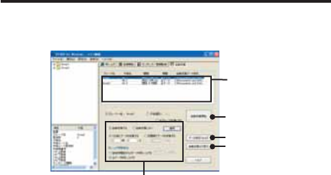
[Registration] Menu
Remote Unit / Relay Unit Registration
Remote Unit Group List
The Group and Remote Unit names will be displayed for all Remote Units
that are registered to that Group in the [Remote Unit / Relay Unit
Registration].
By right clicking on the Remote Unit icon, a menu will appear with
commands for that type of unit.
27
Remote Unit Properties (Remote Unit Info List)
View Remote Unit Info for the unit(s) selected from the Remote Unit List.
Unit Type ---------------The type of unit (RTR-51/52/53 or RVR-52) for the selected
Remote Unit(s) will be displayed.
Group Name ----------The Group Name appears.
Frequency Channel -The Frequency Channel for communication between the Base
Unit and the Remote Units appears.
Remote Unit Name --Displays the name of the selected Remote Unit.
Relay Route Name --Displays the Name of the Relay Route via which the Remote
Units communicate.
Relay Route Frequency Channel Displays the Frequency Channel of the Relay
Route via which the Remote Units communicate.
Relay Unit Number --Displays the No. of the Relay Unit via which the Remote Unit is
connected.
CH1 Upper Limit -----Displays the Upper Limit set in [Monitoring / Warning Monitoring]
for Warning Report.
CH1 Lower Limit -----Displays the Lower Limit set in [Monitoring / Warning Monitoring]
for Warning Report.
CH2 Upper Limit*1 --Displays the Upper Limit set in [Monitoring / Warning Monitoring]
for Warning Report.
CH2 Lower Limit*1 --Displays the Lower Limit set in [Monitoring / Warning Monitoring]
for Warning Report.
Monitoring Interval ---Displays the currently set Monitoring Interval.
Auto Download Interval Displays the currently set Auto Download Interval.
*1ȇFor RTR-53 only
Settings Area
There are four different types of Settings windows: [Download Data] Tab,
[Start Recording] Tab, [Monitoring / Warning Monitoring] Tab, and [Auto
Download] Tab.
Main Unit Info
Open the [Main Unit Info] in the [Help] menu to view the Version Info for the currently
connected RTR-50 Unit.It is also possible to view the battery condition in the RTR-50
Unit.
28
RTR-50 for Windows
Remote Unit / Relay Unit Registration
Basic Procedure for Registration
1.
Connect an RTR-50 Unit with a USB or Serial communication cable to your
computer.
*The default setting for an RTR-50 unit is as a Base Unit.
"ASE5NIT
For details about connecting the RTR-50 with a USB communication cable to
your computer see p.12.
For details about connecting the RTR-50 with a Serial communication cable to
your computer see p.22.
2.
Register Remote Unit Name and Group Name.
Register all Remote Units to be placed.
"ASE5NIT 2EMOTE5NIT
'ROUP
For details about registering units as Remote Unit(s) see p.31.
3.
Register Relay Unit Names and Relay Routes.
"ASE5NIT 2ELAY5NIT 2EMOTE5NIT
'ROUP
2OUTE.AME
For details about Registering Relay Unit(s) see p.37.
NOTE:
There is no need to register a Relay Unit if there are no Relay Units between a
Remote Unit and the RTR-50 Base Unit. However, if communication cannot be
successfully carried out due to poor radio wave reception, please place Relay
Unit(s) between the Remote Unit and the Base Unit.
29
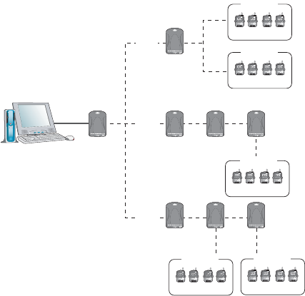
Image of Relay Unit Registration
"ASE5NIT
2ELAY5NIT
2ELAY5NIT 2ELAY5NIT 2ELAY5NIT
2ELAY5NIT 2ELAY5NIT 2ELAY5NIT
2EMOTE5NIT
2EMOTE5NIT
2EMOTE5NIT2EMOTE5NIT
2EMOTE5NIT
'ROUP!
2OUTE
.AME
2OUTE
.AME
2OUTE
.AME
'ROUP"
'ROUP#
'ROUP$ 'ROUP%
Once the registration of a Relay Unit is complete, a Relay Unit Number will
automatically be assigned to each Relay Unit.
Also, when carrying out Relay Unit Registration it is possible to assign a ȨRelay
Route Nameȩ that can be used to make sure that data is transmitted through a
multiple number of Relay Units in the specifi ed route.
NOTEȇ
It is possible to set up so that more than one Relay Unit acts as a relay for the same
Remote Units. However because wireless communication is carried out in Groups of
Remote Units, the same Group will be relayed through different Relay Units causing
ineffi ciency and an increase in the amount of communication time to more than
necessary.
In order to reduce the communication time, please design Relay Routes so that a
particular Group of Remote Units uses the same Relay Unit(s).
30
RTR-50 for Windows
NOTEȇ
A Relay Unit Number will be automatically assigned to Relay Units in the order that
they were registered to each Route.
Communication among Relay Units will occur in sequence from the one that is
closest to the Base Unit. Please keep that in mind when placing the Relay Units.
Exampleȇ
Communication Sequence Order
"ASE5NIT
2ELAY5NIT 2ELAY5NIT 2ELAY5NIT
2EMOTE5NIT
'ROUP
؉Ⴙ
໘Ⴙ
Communication will occur sequentially from the fi rst Relay Unit as shown above.
If the Relay Units are not arranged in numerical sequence from the Base Unit,
the communication route will be as seen below. This will cause not only the
communication distance to increase but also the communication time to increase to
longer than necessary.
"ASE5NIT
2ELAY5NIT 2ELAY5NIT 2ELAY5NIT
2EMOTE5NIT
'ROUP
4.
After each Registration has been completed, please check the communication
status by carrying out a ȨWireless Communication Test.ȩ
31
Registering a Remote Unit
1.
Connect the RTR-50 Main Unit with a USB or Serial Communication Cable to
your computer.
2.
In the Main Window, click [Registration] – [Remote Unit / Relay Unit
Registration].
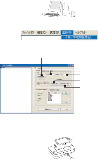
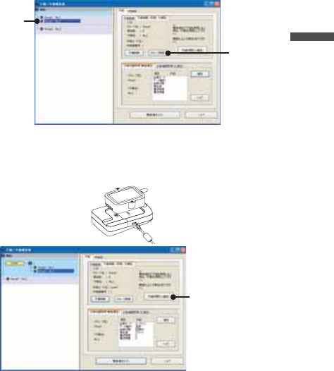
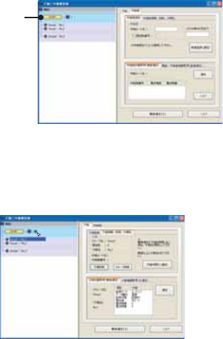
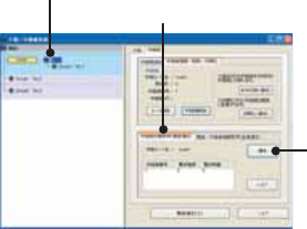
3.
The [Remote Unit / Relay Unit Registration] display will be opened in a new
window.
ΈσȜίྴ
ঊܥྴ
[૧ܰഴȪȫ]δΗϋ
[୭Ȫȫ]δΗϋ
ਔ෨ତ๔
4.
Place the Remote Unit (data logger) you wish to register face down on top of the
RTR-50. After entering the Group Name and Remote Unit name, click the [New
Registration (Communication)] button.
*Up to 8 characters can be entered for Group Name / Remote Unit Name.
A distinction will be made between upper and lower case alphabet. Ex. abc123 and
ABC123 will be treated as different.
*In order to register a Remote Unit, it is also necessary to register a Group Name.
32
RTR-50 for Windows
5.
When successful communication has occurred, the Remote Unit will be
registered in the registration list at the left side of the Main Window.
The registered
Remote Unit
*The registered Remote Unit(s) will appear as [Group Name / Remote Name].
6.
Register Remote Units Sequentially.
Communication Frequency Channel
- It is possible to set one Communication Frequency Channel (channel 0-21) to each
Group.
- If no setting is made, an unused frequency channel will automatically be assigned.If
there are no unused frequency channels, the channel that is used the least shall be
automatically assigned.
-Communication Frequency Channel settings can only be made when registering a new
Group. Once a Communication Frequency Channel setting has been made it cannot
be changed.
33
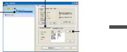
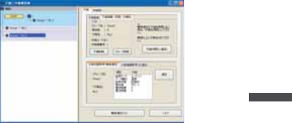
[Get Settings (Communication)] Button
Clicking this button will receive the Registration Info for already registered Remote Units
(current settings).
Place the Remote Unit (data logger) for which you wish to receive settings face down
on top of the Base Unit and click the [Get Settings (Communication)] Button.
When successful communication has occurred, the Group Name and Remote Unit
Name will appear.
If you wish to register the currently displayed Remote Registration Contents without any
changes, click the [New Registration (Communication)] Button to add the received
registration info.
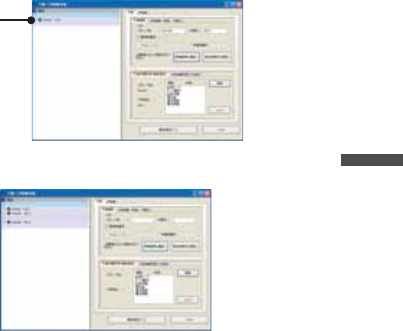
Deletion and Initialization of Remote Units
Registered Remote Units can be deleted, initialized, or deleted in Groups
Click on the [Remote Unit] – [Remote Info / Delete / Initialize] Tab to open the [Remote
Info / Delete / Initialize] window.
Remote Unit Deletion
Select the Remote Unit to be deleted from the registration list and click
the [Delete Remote Unit] button.
ॉੰ̱̹̞ঊܥͬ
఼
[Delete Remote Unit]
button
34
RTR-50 for Windows
U
nit]
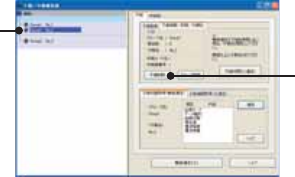
Group Deletion
Select the Group to be deleted from the registration list and click the
[Delete Group] button.
NOTE:
By deleting a Group, it will become impossible to communicate with all Remote
Units registered to that Group.If you wish to carry out communication with any such
units they must be re-registered or initialized.
Select the Group
to be deleted
[Delete Group]
button
Remote Unit Initialization
Place the Remote Unit that you wish to initialize on top of the Base Unit
connected to your computer and click the [Initialize Remote Unit
(Communication)] button.
[Initialize Remote Unit
(Communication)]
button
35
NOTEȇ
- By initializing, all info saved in the Remote Unit will be erased and will be returned
to as it was when it left the factory.
The Default Settings are Group Name: Group 1 / Remote Unit: Sr001 /
Communication Frequency: 0
- When initializing a currently registered Remote Unit, the Registration Info will also
be erased from the registration list.
Get Remote Unit Recording Settings (Wireless Communication)
It is possible to gather the current Remote Unit Recording Settings: Recording Mode /
Type of Data / Recording Status / Current Readings / Radio Wave Strength / Battery
Level by selecting [Get Remote Unit Recording Settings (Wireless Communication)].
Recording Mode -----------The selected recording mode will be displayed: Endless or
One Time.Endless Mode--- When the logger has reached its
maximum number of readings (16,000 readings possible /
8,000 of Temp and Humidity for RTR-53), the oldest data
reading will be overwritten and recording will continue.
One-time Mode--- Recording will automatically stop when the
logger has reached its maximum number of readings (16,000
readings possible / 8,000 of Temp and Humidity for RTR-53).
Type of Data ----------------Temperature, Humidity, Voltage, Pulse, Event can be viewed
here.
Current Readings ---------The currently recorded data is displayed here.
Radio Wave Strength -----Displays the Radio Wave Strength of wireless communication
between Units.(0 – Weak < 5 – Strong)
Battery Level ----------------The remaining battery level for the Remote Unit will be
displayed.(0 – No Battery < 5 – Full)
36
RTR-50 for Windows
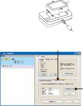
1.
Check if the Base Unit is properly connected to the computer.
2.
From the registration list, select the Remote Unit which you wish to view the
Registration Recording Settings from and click the [Get Remote Unit Recording
Settings (Wireless Communication)] Tab.
ঊܥૂ༭৾ං̱̹̞
ঊܥ఼ͬ
[Communication]
button
[Get Remote Unit Recording Settings (Wireless Communication)] Tab
3.
Click the [Communication] button.
NOTEȇ
If a communication error has occurred, please check the communication status by
carrying out aȨWireless Communication Test.ȩ(See p. 44 for details)
37
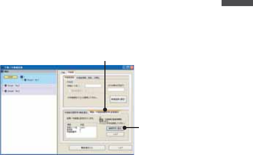
Get Remote Unit Info (Optical Communication)
It is possible to gather the current Remote Unit Info: Group Name / Frequency Channel
/ Remote Unit name / Registration Status by selecting [Get Remote Unit Info (Optical
Communication)].
Group Name ----------Group Name will be displayed.
Frequency Channel -Frequency Channel will be displayed.
Remote Unit Name --Remote Unit Name will be displayed.
Registration Status --Displays whether the Remote Unit has been registered in the
Remote Unit Registration List or not.
1.
Place the Remote Unit you wish to view the Registration Info from face down on
the Base Unit that is connected to your computer.
2.
Select the [Get Remote Unit Info (Optical Communication)] Tab and click the [Get
Remote Unit Info (Communication)] button.
[Get Remote Unit Info
(Communication)]
button
[Get Remote Unit Info (Optical Communication)] Tab
38
RTR-50 for Windows
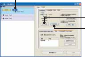
Registering a Relay Unit
1.
Connect the Relay Unit you wish to register to your computer with a USB or
Serial Communication Cable.
2.
Click the [Relay Unit] Tab and enter a Relay Route Name. Then click the [New
Registration (Communication)] button.
Relay Route Name
Memo
[Relay Unit] Tab
[New Registration
(Communication)]
button
[Memo]
It is helpful to make a memo entry here in order to distinguish between Relay
Units.
(Up to 8 characters can be entered.)
You may leave this fi eld blank if not necessary and should note that changes
cannot be made after registering a Relay Unit.If you wish to make changes, it is
necessary to create the Relay Route again.
39
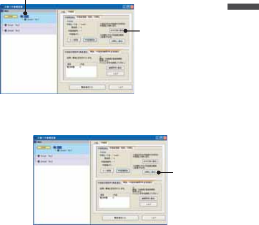
3.
When successful communication has occurred, the Relay Route and Relay Unit
will be registered.
*A Relay Unit Number for all registered Relay Units will be automatically assigned in
the order that they were registered.(Not possible to change)
ഴ̯̹ͦ
ಎࠑσȜΠ͂ಎࠑܥ
The registered Relay Unit and Remote Unit Group will appear in different
background colors so as to be easily distinguishable.
Connect a Remote Unit via Relay Unit(s)
1.
From the Registration List, select the Remote Unit which you wish to connect to
the Base Unit via Relay Unit(s). Then drag the Remote Unit to the Relay Unit to
which you wish to connect and drop it.
40
RTR-50 for Windows
2.
The message [Relay Settings for Selected Remote Completed] will appear and
the Remote Unit will be added under the location in the Relay Route in the
Registration List.
Removing a Remote Unit from a Relay Route
1.
Select the Remote Unit which you wish to remove from the Relay Route. Then
drag the Remote Unit to the Base Unit Icon and drop it.
2.
The location of the Remote Unit will be returned just under the Base Unit in the
registration list.
*Also, by a right clicking the mouse and then clicking on [No Relay], the location of
the Remote Unit will be returned to the Base Unit as above.
41
Deletion and Initialization of Relay Units
Registered Relay units can be deleted or initialized.
Click on the [Relay Unit] – [Relay Unit Info / Delete / Initialize] Tab to open the [Relay
Unit Info / Delete / Initialize] window.
Relay Unit / Relay Route Deletion
Select the Relay Unit to be deleted from the registration list. Click the
[Delete Relay Unit] if you wish to delete only the Relay Unit and click the
[Delete Route] if you wish to delete the Relay Route.
Select the Relay Unit to be deleted
[Delete Route]
button
[Delete Relay Unit]
button
NOTEȇ
If you wish to delete a Relay Route, the location of all Remote Units belonging to it
will be returned to just under the Base Unit in the Registration List.
42
RTR-50 for Windows
Relay Unit Replacement (For changing a Relay Unit with a new one
due to malfunction or trouble)
Select the Relay Unit you wish to replace from the Registration List and
connect the one you wish to newly register to your computer with a USB
or Serial Communication Cable.
Click the [Replace Unit] button.
ಕփȇ
ഴඤယ͉Ȃஜ͈ಎࠑܥ̧͈͈ͬ֨͜ࠑ̨̳͘ȃ
ུఘ̱̹̞۟ಎࠑܥ఼ͬ
[ུఘ۟Ȫȫ]δΗϋ
ಎࠑܥ͈ܢاȪܥͅ࿗̳ȫ
ܢا̱̹̞ಎࠑܥ͂ΩΕϋͬ USB ̹͉͘ΏςͺσΉȜήσ́୪
̱Ȃ[ܢاȪȫ]δΗϋͬ·ςΛ·̱̳͘ȃ
[ܢاȪȫ]
δΗϋ
43
ಕփȇ
ܢا࣐̠࡛ͬ͂हಎࠑܥͅഴ̯̞ͦ̀ͥૂ༭͉̀ॉੰ̯ͦȂܢેఠȪك
শ͈ેఠȫ̳̈́ͤ͘ͅȃ
RTR-50 ͈ܢેఠ͉Ȃܥ̱͂̀୭̯̞̳ͦ̀͘ȃ
ಎࠑܥેఠ৾ංȪྫȫ
ঐ̯̹ͦσȜΠ͈ಎࠑܥેఠͬ৾ං̱̳͘ȃ
ಎࠑܥ๔ ------------ڎಎࠑܥ͈๔ͬນা̱̳͘ȃ
ഩ෨ޑഽ ---------------ڎಎࠑܥۼ͈ഩ෨ޑഽͬນা̱̳͘ȃȪ0ȇ৻̞ɨ 5ȇޑ̞ )
*ুͤ͢ 1̾PC ͅ߃̞ಎࠑܥȪ̹͉͘ܥȫۼ͈ྫ
͈ഩ෨ޑഽ̳́ȃ
ഩ౻ॼၾ ---------------ڎಎࠑܥ͈ഩ౻ॼၾͬນা̱̳͘ȃȪ0ȇॼၾ̱̈́ɨ 5ȇ૧ȫ
1.
ಎࠑܥેఠͬ৾ං̱̹̞ಎࠑσȜΠͬ୪֚။఼̥̱̳ͣ͘ȃ
2.
[ಎࠑܥેఠ৾ං ]Ηή఼̱ͬȂ[ ]δΗϋͬ·ςΛ·̱̳͘ȃ
[ ]δΗϋ
[ಎࠑܥેఠ৾ංȪྫȫ]Ηή
ಎࠑܥ఼̳ͬͥ
3.
ࠫض̦ນা̯̳ͦ͘ȃ
ಕփȇ
ͅ෴̱̹ાࣣȂ[ྫΞΑΠ ]́ഩ෨͈ږ̱̩̺̯̞ͬ̀ȃ
ȪP. 4 4 ४ચȫ
44
RTR-50 for Windows
ܥ /ಎࠑܥૂ༭৾ංȪೄ୪ȫ
ഴ̯̞ͦ̀ͥȂܥ̹͉͘ಎࠑܥ͈ૂ༭ͬ৾ං̧̳̭̦̳ͥ͂́͘ȃ
ܥ͈ાࣣ
ഩ౻ॼၾ ---------------ഩ౻ॼၾͬນা̱̳͘ȃȪ0ȇॼၾ̱̈́ɨ 5ȇ૧ȫ
ಎࠑܥ͈ાࣣ
ಎࠑσȜΠྴ ---------ಎࠑσȜΠྴͬນা̱̳͘ȃ
ਔ෨ତ ------------------ಎࠑܥ̦௺̳ͥಎࠑσȜΠ͈ਔ෨ତ๔ͬນা̱̳͘ȃ
ಎࠑܥ๔ ------------ಎࠑܥ๔ͬນা̱̳͘ȃ
ഩ౻ॼၾ ---------------ഩ౻ॼၾͬນা̱̳͘ȃȪ0ȇॼၾ̱̈́ɨ 5ȇ૧ȫ
1.
ૂ༭ͬ৾ං̱̹̞ܥ̹͉͘ಎࠑܥͬΩΕῧ USB ̹͉͘ΏςͺσΉȜή
σ́୪̱̳͘ȃ
2.
[ܥ /ಎࠑܥૂ༭৾ංȪೄ୪ȫ]Ηή఼̱ͬȂ[ૂ༭৾ංȪೄ୪ȫ]
δΗϋͬ·ςΛ·̱̳͘ȃ
[ૂ༭৾ංȪȫ]
δΗϋ
[ܥ /ಎࠑܥૂ༭৾ංȪೄ୪ȫ]Ηή
3.
ࠫض̦ນা̯̳ͦ͘ȃ
45
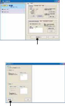
ྫΞΑΠ
1.
[ঊܥ /ಎࠑܥഴ ];ͻϋΡ;͈ [ྫΞΑΠ ]δΗϋͬ·ςΛ·̱̳͘ȃ
[ྫΞΑΠ ]δΗϋ
2.
[ঊܥ /ಎࠑܥͬΞΑΠ̳ͥ ] / [ ঊܥΈσȜί ] / [ ಎࠑσȜΠ ]͈3ਅ႒̥
఼༹༷̱ͣ॑ͬȂ[ٳই ]δΗϋͬ·ςΛ·̱̳͘ȃ
[ٳই ]δΗϋ
ঊܥ /ಎࠑܥͬΞΑΠ̳ͥ --- ഴ̯̞͈ͦ̀ͥ̀ঊܥ͂ಎࠑܥ͈ΞΑΠ
࣐̞̳ͬ͘ȃ
ঊܥΈσȜί -------------------------- ঊܥΈσȜίྴςΑΠ఼̯̹́ͦΈσȜί͈ঊ
ܥ͈ഩ෨ޑഽͬນা̱̳͘ȃ
ಎࠑσȜΠ -----------------------------ȮΞΑΠ͈ঐȯ́ "͈̀σȜΠ "ͬΙͿΛ
·̱̹ાࣣ͉͈̀σȜΠͬࠐဇ̳ͥಎࠑܥ͂ঊ
ܥ͈ഩ෨ޑഽͬΞΑΠ̱̳͘ȃ"ঐ̱̹σȜΠ "
ͬΙͿΛ·̱̹ાࣣ͉ȮಎࠑσȜΠྴȯςΑΠ́
ΞΑΠ̱̹̞ಎࠑσȜΠͬঐ̱̩̺̯̞̀ȃ
*ܥ͂ೄ୪̳ͥঊܥ͉ΞΑΠ̵̱ͭ͘ȃ
46
RTR-50 for Windows
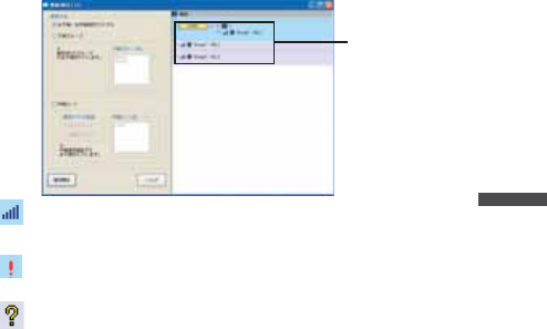
3.
ΞΑΠࠫضֲ̦௰͈;ͻϋΡ;ͅນা̯̳ͦ͘ȃ
ΞΑΠࠫض
--- ଼ȁഩ෨ޑഽͬਸུ͈ତ́ນা̱̳͘ȃȪMin:1 / Max:5ȫ
ಎࠑܥ͈ાࣣ͉Ȃಎࠑܥ๔̦ 1̯̞ಎࠑܥȪಎࠑܥ 1͈শ͉
ܥȫ͈͂ഩ෨ޑഽͬນা̱̳͘ȃ
--- ෴ȁ̱̦ͬ̀෴̱̹ঊܥ̹͉͘ಎࠑܥ͈ાࣣͅ
ນা̱̳͘ȃ
--- ༹༷॑́ঐ̯̥̹ͦ̈́̽Ȫ̱̥̹̈́̽ȫঊܥ̹͉͘ಎࠑ
ܥ͈ાࣣͅນা̱̳͘ȃ
*ͅ෴̱̹ાࣣ͉Ȃঊܥ /ಎࠑܥ͈պ౾ږȂഩ౻ॼၾ͈ږ࣐̩̺ͬ̽̀
̯̞ȃ
47
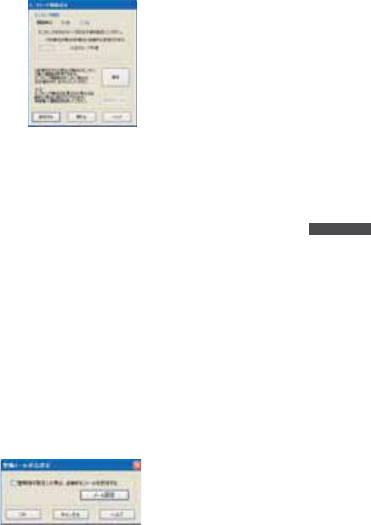
ݟ̞ષ̬୭
ιͼϋْ࿂ͤ͢Ȃঊܥ 1రȂ̹͉͘ΈσȜί֚گ́ΟȜΗݟ̞ષ̬͈୭̧̦̳́͘ȃ
1.
ঊܥ 1ర͈ݟ̞ષ̬͈ાࣣȂऒ௰͈ঊܥ֚။̥ͣȂݟ̞ષ̬̹̞ঊܥ఼̱ͬ
̳͘ȃΈσȜί֚گ́ݟ̞ષ̬̱̹̞ͬાࣣȂঊܥ֚။̥ͣΈσȜίྴέσ
Θ఼̱̳ͬ͘ȃ
ঊܥ̹͉͘
ΈσȜί఼ͬ
[ݟ̞ષ̬ ]
δΗϋ
[મळ୭ ]
δΗϋ
2.
༹༷Ȃݟ̞ષ̬ૄͬ୭̱Ȃ[ݟ̞ષ̬ ]δΗϋͬ·ςΛ·̳ͥ͂Ȃݟ̞
ષ̬ͬٳই̱̳͘ȃݟ̞ષ̬ࠫض͉Ȃْ࿂ષ͈ [ݟ̞ષ̬ેޙ ]ͅນা̯̳ͦ͘ȃ
ΈσȜίȟঊܥȁȪྫ͈͙ȫ
ঐ̱̹ঊܥ͈͙
ঊܥςΑΠ֚။́ঐ̯̹ͦঊܥ 1ర͈ΟȜΗͬݟ̞ષ̬̳͘ȃ
ΈσȜί֚گ
ঊܥςΑΠ֚။́ঐ̯̹ͦΈσȜί͈ΟȜΗ֚ͬگ́ݟ̞ષ̬̳͘ȃ
ಕփȇ
*ݟ̞ષ̬̹έͼσ͉ু൲എͅ RTR-50 for WIndows ͬͼϋΑΠȜσ̱̹έσ
Θͅ ȩ ΈσȜίྴ _ঊܥྴ _ັশ࣫ .ڐಫঊ ȩ̞̠͂έͼσྴ́༗ం̯̳ͦ͘ȃ
ݟ̞ષ̬ૄ
ܱΟȜΗ
ܱΟȜΗͬݟ̞ષ̬̳͘ȃ
ݟ̞ષ̬শۼঐ
डਞܱΟȜΗ̥ͣঐশۼஜ͈ܱ́͘ΟȜΗͬݟ̞ષ̬̳͘ȃౙպ͉ 1শۼౙ
պȆ1ౙպ఼̧̥̳̭̦̳ͣͥ͂́͘ȃݟ̞ષ̬শۼͬঐ̧̱̹͂ͅঐ̯ͦ
̹শۼ͈ΟȜΗ̦ܱ̯̞̞ͦ̀̈́ાࣣ͉Ȃ࡛ह༗ం̯̞ܱͦ̀ͥΟȜΗͬ
ݟ̞ષ̬̳͘ȃ

48
RTR-50 for Windows
ݟ̞ષ̬ેޙȁȪݟ̞ષ̬̹ঊܥ̹͉͘ΈσȜί͈ૂ༭ͬນা̱̳͘ )
ΈσȜίྴ ------------ݟ̞ષ̬̹ঊܥ͈ΈσȜίྴ
ঊܥྴ ------------------ݟ̞ષ̬ঊܥྴ
ٳই༹༷ ---------------௲শΑΗȜΠȟထΑΗȜΠ
ܱκȜΡ ------------χϋΗͼθȟϋΡτΑ
ٳইশ ---------------ܱͬٳই̱̹শ
ܱۼڞ ---------------ܱΟȜΗ͈ۼڞ
ΟȜΗਅ႒ ------------أഽȟഩգȟΩσΑȟ Event
ಕփȇ
-͈ાࣣ͈͙ݟ̞ષ̬फ͙ΟȜΗၾͬίυΈτΑΨȜ́ນা̱̳͘ȃ
-ঊܥུఘ̦Ȃܱထಎ͈শ͉ܱΟȜΗ̱̈́́ρȜ̳͂̈́ͤ͘ȃ
-ܱٳই̥࡛ͣশത͈ܱ́͘ΟȜΗͬݟ̞ષ̬̳͘ȃঊܥུఘ͉Ȃݟ̞ષ̬ಎݞ
͍ݟ̞ષ̬ࢃ͜ࠑ̱ܱ̱̫̳̀͘ȃ
-ঊܥུఘ͈ܱΟȜΗ͉Ȃ૧̹ܱͬͅΑΗȜΠ̳ͥ͂ક̢̱̞̳̀͘͘ȃྌȂݟ
̞ષ̬̹ܱΟȜΗ͉ȂུͺίςΉȜΏοϋͬਞၭ̵̯̹ͤȂΩΕϋ͈ഩ࡙ͬ
OFF ̳ͥ͂ͅક̢̱̞̳̀͘͘ȃြ்̺̫̩ͥέͼσͅ༗ం̳ͥম̤̳̳ͬ
̱̳͛͘ȃ
- ॼၾນা̧̦̯̩̹̈́̽̀ͤঊܥུఘסએͅ BAT ζȜ·̦ນা்̯̹ͦͣ͛
ͅഩ౻࣐۟ͬ̽̀ئ̯̞ȃ
ંȂഩ౻࣐̠۟ͬ͂ঊܥུఘ͉ςΓΛΠ̯ܱͦΟȜΗ̦ક̳ͥાࣣ̦̜ͤ
̳͘ȃຈါܱ̈́ΟȜΗ͉ݟ̞ષ̬࣐̞ͬέͼσ͒༗ం̱̤̞̀̀ئ̯̞ȃ
- USB ́ΟȜΗݟ̞ષ̬ಎͅͺίςΉȜΏοϋͬޑଷਞၭ̱̹ાࣣ͉ USB
̦ະհ̈́ͥͅાࣣ̦̜̳ͤ͘ȃ̷͈̠̈́͢ાࣣ͉ USB ΉȜήσͬொ̱ೄ̱̩̀
̺̯̞ȃ
49
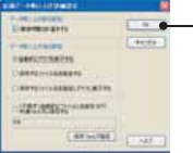
[મळ୭ ]δΗϋ
ݟ̞ષ̬ஜ͈୭Ȃݟ̞ષ̬ࢃ͈ੜၑ఼̧༹༷̳ͬ́͘ȃ
[OK]
button
ຈါ̈́ࣜ࿒ͅΙͿΛ·̱ͬ̀Ȃ[OK] δΗϋͬ·ςΛ·̳ͥ͂Ȃ୭̯̳ͦ͘ȃ
ΟȜΗݟ̞ષ̬ஜ͈୭
শۼ͈ࠗॳ̳ͬͥ ---------- ಎࠑܥͬࠐဇ̱̞̀ͥાࣣͅࡠͤȂఘ͈̥̥ͅ
ͥশۼͬેఠΘͼͺυΈδΛ·ᾼນা̱̳͘ȃ
̹̺̱Ȃশۼͬນা̳̹͉ͥ͛ͅಎࠑܥ֚͂ഽ
̳ͬͥຈါ̦̜͈ͥ́ 1ঊܥͬݟ̞ષ̬̹ͥ͛
ͅȂ̷̤͢ಎࠑܥరତ x 20 ຟ͈শۼ̦ح̯̳ͦ͘ȃ
শۼͬນা̵̯̹̞ાࣣ͉ͅΙͿΛ·̫ͬ̾̀
̩̺̯̞ȃȪಎࠑܥͬࠐဇ̱̞̞̀̈́ાࣣ͉حশۼ
͉̩̈́ȂΙͿΛ·͈ခྫͅ۾̴̷̤͈ͩͣ͢শ
ۼ͉ນা̯̳ͦ͘ȃȫ
ΟȜΗݟ̞ષ̬ࢃ͈୭
ু൲എͅΈρέນা̳ͥ -----------ݟ̞ષ̬̹ΟȜΗͬু൲എͅΈρέͅນা̱̳͘ȃ
ΟȜΗͬ༗ం̱̹̞ાࣣ͉ͅٳ̞̹Έρέ͈έ
ͼσιΣνȜ̥ͣ༗ం̱̩̺̯̞̀ȃ
༗ం̳ͥέͼσྴͬঐ̳ͥ --1 ঊܥΟȜΗͬݟ̞ષ̬̹ࢃͅȮέͼσͬ༗ం̳
ͥȯΘͼͺυΈδΛ·Α̦ນা̯͈ͦͥ́Ȃ༗ం
̱̹̞έͼσྴͬঐ̱̩̺̯̞̀ȃΈρέͅ
ນা̱̹̞ાࣣ͉ͅ༆ഷ༗ంέͼσͬΈρέ́
ٳ̞̩̺̯̞̀ȃ
༗ం̳ͥέͼσྴͬঐ̱Έρέͅນা̳ͥ
ષܱ͈Ȯ༗ం̳ͥέͼσྴͬঐ̳ͥȯȂȮু൲
എͅΈρέͬນা̳ͥȯ̦ਜ਼࣐̯̳ͦ͘ͅȃ
ˍঊܥ̿̾ু൲എͅέͼσͅྴஜ̫ͬ̾̀ވέσΘͅ༗ం̳ͥ
ݟ̞ષ̬̹ΟȜῌু൲എͅέͼσྴ̫ͬ̾̀
Ȫ*ΈσȜίྴ /ঊܥྴ /ັশ࣫ȅڐಫঊȫঐ
̯̹ͦέσΘͅڒො̯̳ͦ͘ȃة͜ঐ̱̞̀
̞̈́ાࣣ͉ু൲എͅͺίςΉȜΏοϋͬͼϋΑ
ΠȜσ̱̹έσΘͅڒො̯̳ͦ͘ȃΈρέͅນ
া̱̹̞ાࣣ͉ͅ༆ഷ༗ంέͼσͬΈρέ́ٳ
̞̩̺̯̞̀ȃ

50
RTR-50 for Windows
ܱٳই୭
ྫȂ̱̩͉́͜Ȃܱٳই͈୭̧̦̳́͘ȃ
ιͼϋْ࿂͈ [ܱٳই ]Ηήͬ·ςΛ·̱̀Ȃܱٳইْ࿂ͬٳ̧̳͘ȃ
ྫ͈ાࣣ
[ܱٳই ]Ηή
[ܱٳই ]δΗϋ
[୭ ]δΗϋ
[ܱ೪গ ]δΗϋ
1.
ঊܥ 1ర͈ܱٳই୭͈ાࣣȂऒ௰͈ঊܥ֚။̥ͣ୭̱̹̞ঊܥ఼̱ͬ
̳͘ȃΈσȜί֚گܱ́ٳই୭̱̹̞ͬાࣣȂঊܥ֚။̥ͣΈσȜίྴέ
σΘ఼̱̳ͬ͘ȃ
2.
ڎ୭̱ͬȂ[ܱٳই ]δΗϋͬ·ςΛ·̳ͥ͂Ȃ୭̦ۖၭ̱̳͘ȃ
[ܱٳই ]δΗϋ
ঐ̯̹ͦૄ́ঊܥ͈ܱͬٳই̱̳͘ȃ
*̹̺̱Ȃྫ͈ાࣣ́Ȯྫܱͥ͢ͅٳই̦গȯ̯̞ͦ̀ͥঊܥͅ
చ̱͉ܱ̀ͬٳই̵̧́ͭ͘ȃમ̱̩͉ [મळ୭ ]δΗϋȪP. 5 3 ȫͬ४ચ̱̀
̩̺̯̞ȃ
*ܱٳইږιΛΓȜΐΘͼͺυΈδΛ·Αͬນা୭̱̹ͅાࣣȂ"Shift δ
Ηϋ (΅ȜδȜΡ ) ͬ؋̱̦̈́ͣζ;Αֲ·ςΛ· "̳ͬͥ͂Ȃষܱٝٳইশͅ
ठഽږιΛΓȜΐΘͼͺυΈδΛ·Α̦ນা̯̳ͦ͘ȃ
[୭ ]δΗϋ
఼̱̹ঊܥ͈୭̱ͬ̀ນা̱̳͘ȃ
[ܱ೪গ ]δΗϋ
఼̱̹ঊܥȂ̹͉͘ΈσȜί͈ܱͬ೪গ̱̳͘ȃ
*̹̺̱Ȃྫ͈ાࣣ́Ȯྫܱͥ͢ͅٳই̦গȯ̯̞ͦ̀ͥঊܥͅ
చ̱͉ܱ̀ͬ೪গ̵̧́ͭ͘ȃ
મ̱̩͉̤ঀ̞͈ঊܥ͈৾ե୰ྶ̮ͬ။̩̺̯̞ȃ
51
ܱٳই༹༷
ΈσȜί ---------------ঊܥςΑΠ֚။́ঐ̯̹ͦΈσȜίྴ̦ນা̯̳ͦ͘ȃ
ঊܥ ---------------------ঊܥςΑΠ֚။́ঐ̯̹ͦঊܥྴ̦ນা̯̳ͦ͘ȃ
ঐ̱̹ঊܥ͈͙ ---ঐ̯̹ͦঊܥ 1ర͈ܱͬٳই̱̳͘ȃ
ΈσȜί֚گ ---------
ঐ̯̹ͦΈσȜί͈ঊܥ̀ͅచ̱֚̀گܱ́ͬٳই̱̳͘ȃ
ܱٳইশ
ထΑΗȜΠ ---------ঊܥུఘ̦ထ̯̹ͦশܱͤͬ͢ٳই̱̳͘ȃܱٳই
শ͈වႁ͉ාȂȂȂশȂȂຟ͈ౙպ࣐̞̳́͘ȃ
ܢ͉ΘͼͺυΈδΛ·Αܳ൲শ͈শ̦ນা̯̳ͦ͘ȃ
Ȫܢ͉ྚྖͬ୨ͤષ̬̜̳̀ͤ͘ȃȫ
௲শΑΗȜΠ ---------ঊܥུఘ̦ೄ̻ܱͬͅٳই̱̳͘ȃܱٳইশ͈වႁ͉ຈ
ါ̵̜ͤͭ͘ȃ
ಕփȇ
-ྫ͈ાࣣ͉ͅ௲শΑΗȜΠ̵̧͉́ͭ͘ȃ̹͘ܥ̥
ͣঊܥ͈́͘শۼͬࣉၪ̱̀ထশۼͬ୭̱̩̺̯̞̀ȃ
࡛ह̥̥̥ͣͥͅশۼͬح̱̹শ࣫ͤ͢͜ထٳইশۼ
்̦̞ાࣣ͉ͅΑΗȜΠ̵̧́ͭ͘ȃȪρȜιΛΓȜΐ̦ນা
̯̳ͦ͘ȃȫ
ٳইশۼ͈࿒հ̷͉̤͢ 1σȜΠ̜̹ͤ (ಎࠑܥ͈రତ + 1)
x 20 ຟ̱̩̺̯̞͂̀ȃ
̹͘ȂΈσȜί֚گ́ٳই̳ͥાࣣȂಎࠑܥͬࠐဇ̳ͥঊܥ͞
ܥ͂ೄ୪̳ͬͥঊܥ̦̜ͥ୭͈̈́̓ાࣣ͉֚ͅ๔
শۼ͈ಿ̞ঊܥͅచ̱͈ܱ̀ٳইထশۼͬ୭̱̩̺̯̀
̞ȃ
࡛हশ ---------------࡛हশ͉ΩΕϋ͈ΏΑΞθັͬນা̱̞̳̀͘ȃထΑ
ΗȜΠ̳ͬͥાࣣܱٳইশ͉࡛हশͤ͢ྚြ͈শ࣫ͬ୭
̱̩̺̯̞̀ȃ
ထশ ---------------୭̯̹ܱͦۼڞȂܱٳইশͤ͢Ȃထਞၭশͬࠗॳ
̱̳͘ȃ(ొ̱ȂܱκȜΡͬϋΡτᾼ̱̹ાࣣ͉ນা̯
̵ͦͭ͘ȃ)
ܱۼڞ
1ຟȂ2ຟȂ5ຟȂ10 ຟȂ15 ຟȂ20 ຟȂ30 ຟ Ȃ
1Ȃ2Ȃ5Ȃ10 Ȃ15 Ȃ20 Ȃ30 Ȃ60 ఼̧̥̳ͣ́͘ȃ
ܱκȜΡ
χϋΗͼθκȜΡ ---ܱΟȜΗତ̦ 16000 ࡢȪRTR-53 ͉8000 ࡢȫͅൢో̳ͥ͂
ུఘסએນা໐ͅ FULL ̦ນা̯ͦȂܱͬ೪গ̱̳͘ȃ
ϋΡτΑκȜΡ ---ܱΟȜΗତ̦ 16000 ࡢȪRTR-53 ͉8000 ࡢȫ಼̢ͬͥ͂Ȃ1
๔ࡣ̞ΟȜΗ̥ͣષ̧̱Ȃܱ̫̳ͬ͘ȃ
͈ાࣣ
52
RTR-50 for Windows
௶ౙպ͈୭
[મळ୭ ]δΗϋ
[ܱ೪গ ]δΗϋ
[୭ ]δΗϋ
[ܱٳই ]δΗϋ
1.
ܥਅ఼̱̳ͬ͘ȃ
*RVR-52 ఼̱̹ͬાࣣ͉Ȃ௶ౙպ͈୭ࣜ࿒̦ນা̯̳ͦ͘ȃ
2.
͈শ͈͙ນা̯ͦͥ [મळ୭ ]δΗϋͬ·ςΛ·̳ͥ͂Ȃྫ͈
ίυΞ·Πْ࿂̦ນা̯̳ͦ͘ȃȪP53 ४ચȫ
3.
ڎ୭̱ͬȂ[ܱٳই ]δΗϋͬ·ςΛ·̳ͥ͂Ȃ୭̦ۖၭ̱̳͘ȃ
[ܱٳই ]δΗϋ
ঐ̯̹ͦૄ́ঊܥ͈ܱͬٳই̱̳͘ȃ
*ܱٳইږιΛΓȜΐΘͼͺυΈδΛ·Αͬນা୭̱̹ͅાࣣȂ"Shift δ
Ηϋ (΅ȜδȜΡ ) ͬ؋̱̦̈́ͣζ;Αֲ·ςΛ· "̳ͬͥ͂Ȃষܱٝٳইশͅ
ठഽږιΛΓȜΐΘͼͺυΈδΛ·Α̦ນা̯̳ͦ͘ȃ
[୭ ]δΗϋ
఼̱̹ঊܥ͈୭̱ͬ̀ນা̱̳͘ȃ
[ܱ೪গ ]δΗϋ
఼̱̹ঊܥȂ̹͉͘ΈσȜί͈ܱͬ೪গ̱̳͘ȃ
ܱٳই༹༷
ΈσȜί ---------------ঊܥςΑΠ֚။́ঐ̯̹ͦΈσȜίྴ̦ນা̯̳ͦ͘ȃ
ঊܥ ---------------------ঊܥςΑΠ֚။́ঐ̯̹ͦঊܥྴ̦ນা̯̳ͦ͘ȃ
ঐ̱̹ঊܥ͈͙ ---ঐ̯̹ͦঊܥ 1ర͈ܱͬٳই̱̳͘ȃ
ΈσȜί֚گ ---------
ঐ̯̹ͦΈσȜί͈ঊܥ̀ͅచ̱֚̀گܱ́ͬٳই̱̳͘ȃ
ܱٳইশ
ထΑΗȜΠ ---------ঊܥུఘ̦ထ̯̹ͦশܱͤͬ͢ٳই̱̳͘ȃܱٳই
শ͈වႁ͉ාȂȂȂশȂȂຟȁ͈ౙպ࣐̞̳́͘ȃ
ܢ͉ΘͼͺυΈδΛ·Αܳ൲শ͈শ̦ນা̯̳ͦ͘ȃ
Ȫܢ͉ྚྖͬ୨ͤષ̬̜̳̀ͤ͘ȃȫ
53
௲শΑΗȜΠ ---------ঊܥུఘ̦ೄ̻ܱͬͅٳই̱̳͘ȃܱٳইশ͈වႁ͉ຈ
ါ̵̜ͤͭ͘ȃ
ಕփȇ
-ྫ͈ાࣣ͉ͅ௲শΑΗȜΠ̵̧͉́ͭ͘ȃ̹͘ܥ̥
ͣঊܥ͈́͘শۼͬࣉၪ̱̀ထশۼͬ୭̱̩̺̯̞̀ȃ
࡛ह̥̥̥ͣͥͅশۼͬح̱̹শ࣫ͤ͢͜ထٳইশۼ
்̦̞ાࣣ͉ͅΑΗȜΠ̵̧́ͭ͘ȃȪρȜιΛΓȜΐ̦ນা
̯̳ͦ͘ȃȫ
ٳইশۼ͈࿒հ̷͉̤͢ 1σȜΠ̜̹ͤ (ಎࠑܥ͈రତ + 1)
x 20 ຟ̱̩̺̯̞͂̀ȃ
̹͘ȂΈσȜί֚گ́ٳই̳ͥાࣣȂಎࠑܥͬࠐဇ̳ͥঊܥ͞
ܥ͂ೄ୪̳ͬͥঊܥ̦̜ͥ୭͈̈́̓ાࣣ͉֚ͅ๔
শۼ͈ಿ̞ঊܥͅచ̱͈ܱ̀ٳইထশۼͬ୭̱̩̺̯̀
̞ȃ
-͈ਜ਼੬൝͉୪֚။͈୰ྶͬ४ચ̱̩̺̯̞̀ȃ
࡛हশ ---------------࡛हশ͉ΩΕϋ͈ΏΑΞθັͬນা̱̞̳̀͘ȃထΑ
ΗȜΠ̳ͬͥાࣣܱٳইশ͉࡛हশͤ͢ྚြ͈শ࣫ͬ୭
̱̩̺̯̞̀ȃ
ထশ ---------------୭̯̹ܱͦۼڞȂܱٳইশͤ͢Ȃထਞၭশͬࠗॳ
̱̳͘ȃ(ొ̱ȂܱκȜΡͬϋΡτᾼ̱̹ાࣣ͉ນা̯
̵ͦͭ͘ȃ)
ܱۼڞ
1ຟȂ2ຟȂ5ຟȂ10 ຟȂ15 ຟȂ20 ຟȂ30 ຟ Ȃ
1Ȃ2Ȃ5Ȃ10 Ȃ15 Ȃ20 Ȃ30 Ȃ60 ఼̧̥̳ͣ́͘ȃ
ܱκȜΡ
χϋΗͼθκȜΡ ---ܱΟȜΗତ̦ 16000 ࡢȪRTR-53 ͉8000 ࡢȫͅൢో̳ͥ͂
ུఘסએນা໐ͅ FULL ̦ນা̯ͦȂܱͬ೪গ̱̳͘ȃ
ϋΡτΑκȜΡ ---ܱΟȜΗତ̦ 16000 ࡢȪRTR-53 ͉8000 ࡢȫ಼̢ͬͥ͂Ȃ1
๔ࡣ̞ΟȜΗ̥ͣષ̧̱Ȃܱ̫̳ͬ͘ȃ
[મळ୭ ]δΗϋȪশ͈͙ȫ
ྫܱͥ͢ͅٳইͬগ̳ͥ
୭फ͙ঊܥͅచ̱̀ྫܱ́ٳই /೪গ̦࣐̯ͦ̀͜Ȃ̷͈ঊܥ͉ܱ̦
ٳই̵̯ͦͭ͘ȃ

54
RTR-50 for Windows
ྫܱͥ͢ͅٳইͬݺخ̳ͥ
୭फ͙ঊܥͅచ̱̀গ୭̦̜ͥાࣣ͉Ȃݺخ̱̀ྫܱ́ٳই /೪গ̦
̧̠̳́ͥ̈́ͤ͘͢ͅȃ
ಕփȇ
[OK] δΗϋͬ·ςΛ·̳̭ͥ͂́Ȃ͈ࣽٝ୭̦ষ͈ܱٝٳইশͅခ࢘
̳̈́ͤ͘ͅȃ
௶ౙպȪ͈͙ȫȁ*RVR-52 ͈͙ນা̯̳ͦ͘ȃ
ഩգȁȪུఘסએ͈ౙպ͉ഩգ [V]ȁ̳͂̈́ͤ͘ȃȫ
শ ------------------௶̱̹ۼ͈ഩգܱ̱̳ͬ͘ȃ
------------------
ঐ̯̹ܱͦۼڞಎͅ௶̯̹ͦഩգ͈ܱ̱̳ͬ͘ȃ
ΩσΑȪུఘסએ͈ౙպ͉ΩσΑ [P]ȁ̳͂̈́ͤ͘ȃȫ
ၛ̻ئ̦ͤ ------------ΩσΑ͈ၛ̻ئ̦ܱ̱̳ͤͬ͘ȃ
ၛ̻ષ̦ͤ ------------ΩσΑ͈ၛ̻ષ̦ܱ̱̳ͤͬ͘ȃ
ͼαϋΠȪུఘסએ͈ౙպ͉ΩσΑɃ Hi or Lo ɄȮPȯȫ̳͂̈́ͤ͘ȃȫ
ΩσΑͼαϋΠ͈শܱ̱̳࣫ͬ͘ȃ
55
κΣΗςϋΈ /࠙༭۬ণ୭
༆;ͻϋΡ;́ȂςͺσΗͼθκΣΗͬٳ̧̩̭̦̳͂́͘ȃ
ιͼϋْ࿂͈ [κΣΗςϋΈ /࠙༭۬ণ୭ ]Ηήͬ·ςΛ·̱̀ȂκΣΗςϋΈ /࠙༭۬
ণ୭ْ࿂ͬٳ̧̳͘ȃ
κΣΗςϋΈ֚။̥ͣκΣΗςϋΈ̱̹̞ঊܥȂ̹͉͘ΈσȜί఼̱̳ͬ͘ȃ
κΣΗςϋΈૂ༭ςΑΠ֚။
[κΣΗςϋΈȆ࠙༭۬ণٳই ]δΗϋ
[κΣΗςϋΈۼڞ୭ ]δΗϋ
[࠙༭ιȜσ୭ ]δΗϋ
[࠙༭υΈນা ]δΗϋ
κΣΗςϋΈૂ༭ςΑΠ֚။
ΈσȜίྴ ------------ഴफ͙͈ΈσȜίྴ̦ນা̯̳ͦ͘ȃ
ঊܥྴ ------------------ഴफ͙͈ঊܥྴ̦ນা̯̳ͦ͘ȃ
ષࡠ 1 -------------------ΙλϋΥσ 1͈࠙༭۬ণဥષࡠ̦ນা̯̳ͦ͘ȃ
ئࡠ 1 -------------------ΙλϋΥσ 1͈࠙༭۬ণဥئࡠ̦ນা̯̳ͦ͘ȃ
ષࡠ 2 -------------------ΙλϋΥσ 2͈࠙༭۬ণဥષࡠ̦ນা̯̳ͦ͘ȃ
ئࡠ 2 -------------------ΙλϋΥσ 2͈࠙༭۬ণဥئࡠ̦ນা̯̳ͦ͘ȃ
κΣΗ ------------------κΣΗςϋΈ̱̹̞ͬঊܥͅΙͿΛ·̫̳ͬ̾͘ȃ
[κΣΗςϋΈ୭ ]
κΣΗςϋΈ̳ͥ
κΣΗςϋΈૂ༭ςΑΠ֚။͂Ⴒ൲̱̞̳̀͘ȃΙͿΛ·̳ͥ͂ঐ̯̞ͦ̀ͥঊ
ܥ͈κΣΗςϋΈ୭̦་ࢵ̯̳ͦ͘ȃ
ۼڞ
κΣΗςϋΈۼڞ୭ΘͼͺυΈδΛ·Ά୭̯̹ͦۼڞ̦ນা̯̳ͦ͘ȃ
κΣΗςϋΈۼڞ͉ΈσȜίވ͈ۼڞ̳̈́ͤ͘ͅȃ
[κΣΗςϋΈۼڞ୭ ]δΗϋ
κΣΗςϋΈۼڞͬঐ̧̳̭̦̳ͥ͂́͘ȃ
"κΣΗςϋΈ̳ͥ "ͅΙͿΛ·̱̀Ȃ[κΣΗςϋΈۼڞ୭ ]δΗϋͬ·ςΛ·̱Ȃ
56
RTR-50 for Windows
κΣΗςϋΈۼڞͬ୭̱̳͘ȃ
ಕփȇ
ຟౙպ́୭̳ͥાࣣ͉ 20 ຟոષȂౙպ́୭̳ͥાࣣ͉ 1ոષͅ୭̱̩̺̀
̯̞ȃ
̹͘Ȃ࡛ह఼̯̞ͦ̀ͥঊܥ͈̥̥ͥͅশۼոષ͈শۼͬঐ̱̩̺̯̞̀ȃ
[࠙༭୭ ]
࠙༭ͬ୭̳ͥાࣣȂ֚။̥ͣঊܥ఼̱ͬȂ୭̱̹̞ౙպ͍ͬȂCh.1 ̹͉͘
Ch.2 ͬΙͿΛ·̱̀Ȃତͬවႁ̱̳͘ȃ[ഐဥ ]δΗϋͬ·ςΛ·̳ͥ͂Ȃ୭̦ഐ
ဥ̯̳ͦ͘ȃ
[࠙༭ιȜσ୭ ]δΗϋ
࠙༭୭́ȂκΣΗςϋΈΟȜΗ̦୭̱̹ତ಼̢̹ͬાࣣȂ࠙༭ιȜσͬ
̧̳̭̦̳ͥ͂́͘ȃ[࠙༭̦อ̱̹ાࣣȂু൲എͅιȜσ̳ͬͥ ]ͅΙͿΛ
·̱ͬ̀Ȃ[OK] δΗϋͬ·ςΛ·̱̩̺̯̞̀ȃ
ιȜσ͈મळ୭͉Ȃ[ιȜσ୭ ]࣐̞̳́͘ȃ
*ιȜσ୭̞͉̾̀ͅ P61 ͬ४ચ̱̩̺̯̞̀ȃ
[࠙༭υΈນা ]δΗϋ
57
࠙༭̦̜̹̽ાࣣȂ͈̀࠙༭͈υΈͬࡉ̧̭̦̳ͥ͂́͘ȃ
࠙༭υΈْ࿂
࠙༭শ࣫ ---------------࠙༭̦อ̱̹শ࣫ͬນা̱̳͘ȃ
*̹̺̱Ȃ1κΣΗςϋΈ͈̦ਞၭ̱̹শത͈শ࣫́षͅ
࠙༭̦อ̱̹শ͉࣫͂։̳̈́ͤ͘ȃ
ΈσȜίྴ ------------࠙༭̦อ̱̹ΈσȜίྴͬນা̱̳͘ȃ
ঊܥྴ ------------------࠙༭̦อ̱̹ঊܥྴͬນা̱̳͘ȃ
࠙༭ ------------------࠙༭ͬນা̱̳͘ȃ
*̹̺̱Ȃ1κΣΗςϋΈ͈̦ਞၭ̱̹শത͈࠙༭́
ಎ͈ΟȜΗ͈ଔ֊ͅ۾̱͉̀ד̵̯ͦͭ͘ȃ
ಕփȇ
࠙༭υΈ͉डఱ 1000 ࡢ́͘༗ం̧̳́͘ȃ1000 ࡢոષ࠙༭̦อ̱̹ાࣣ͉ͅȂ
ͺίςΉȜΏοϋͬͼϋΑΠȜσ̱̹έσΘͅȮ࡛हশ࣫ + WarningLogList.wlfȯ
̞̠͂έͼσ̦ু൲എͅै଼̯ͦȂْ̭͈࿂͈υΈນা͉·ςͺ̯ͦड̥ͣນ
া̯̳ͦ͘ȃஜ͈ٝυΈͬ४ચ̱̹̞ાࣣ͉ͅȮυΈͬٳ̩ȯδΗΰ̭͈έͼ
σͬঐ̱̩̺̯̞̀ȃυΈͬ༗ం̱̹̞ાࣣ͉ͅȮυΈͬ༗ంȯδΗΰυΈͬ
έͼσͅ༗ం̱̩̺̯̞̀ȃ
[κΣΗςϋΈȆ࠙༭۬ণٳই ]δΗϋ
̭͈δΗϋͬ·ςΛ·̳̭ͥ͂́Ȃ୭̱̹͈́κΣΗςϋΈ /࠙༭۬ণْ࿂̦༆
;ͻϋΡ;́ٳ̧̳͘ȃ
ಕփȇ
[κΣΗςϋΈȆ࠙༭۬ণٳই ]δΗϋͬ·ςΛ·̳ͥ͂Ȃഴ̯̞ͦ̀ͥΈσȜ
ί͈ତȂκΣΗςϋΈْ࿂̦༆;ͻϋΡ;́ٳ̧̳͘ȃ
κΣΗςϋΈΈρέْ࿂
58
RTR-50 for Windows
κΣΗςϋΈȆ࠙༭۬ণْ࿂́ڎਅ୭̱ͬȂ[κΣΗςϋΈȆ࠙༭۬ণ ]δΗϋͬ·ςΛ
·̳ͥ͂ȂκΣΗςϋΈْ࿂̦༆;ͻϋΡ;́ٳ̧̳͘ȃ
ಕփȇ
κΣΗςϋΈْ࿂͉Ȃഴ̯̞ͦ̀ͥΈσȜί͈ତȂ༆;ͻϋΡ;́ٳ̧̳͘ȃ
[೪গ ]δΗϋ
ঊܥྴ
ΈσȜίྴ
;ͻϋΡ;͈ΗͼΠσͅΈσȜίྴ̦ນা̯̳ͦ͘ȃ
ಕփȇ
-κΣΗςϋΈಎͅঊܥ͈ഴඤယͬ་ࢵ̱̞̠̱̩̺̯̞̈́̀͢ͅȃ
-κΣΗςϋΈಎ͉ͅఈ̵̧͈̳̭͉ͬͥ͂́ͭ͘ȃ֚ഽ೪গδΗϋͬ؋̱̥̀
ͣȂκΣΗςϋΈْ࿂̲̩̺̯̞ͬ̀ȃ
-κΣΗςϋΈশۼಎͅু൲ਓਬশۼ̹̈́̽ͅાࣣ͉ͅু൲ਓਬ͈ۼ͉κΣΗςϋ
ΈȆ࠙༭۬ণ̦ಎ౯̯ͦু൲ਓਬ̦ਞၭ̱̺̞κΣΗςϋΈ̦ठٳ̯̳ͦ͘ȃ
[೪গ ]δΗϋ
κΣΗςϋΈȆ࠙༭۬ণͬ೪গ̱̳͘ȃˍ͈̾;ͻϋΡ;́ [೪গ ]δ
Ηϋͬ؋̳͂Ȃ͈̀ΈσȜί͈κΣΗςϋΈȆ࠙༭۬ণ̦೪গ̯ͦ͘
̳ȃ
*1 ͈̾;ͻϋΡ;͈κΣΗςϋΈȆ࠙༭۬ণ̺̫ͬ೪গ̵̧̳̞̠̭͉ͥ͂͂́ͭ͘ȃ
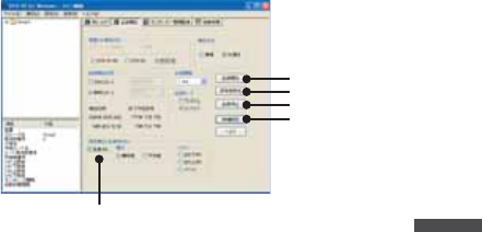
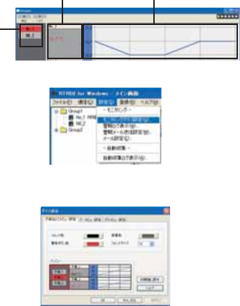
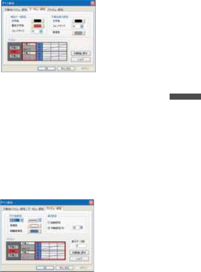
κΣΗςϋΈΈρέ୭
κΣΗςϋΈΈρέ͈ڎਅΫνȜ୭̧̦̳́͘ȃ
59
ঊܥྴςΑΠ
ΟȜΗΫνȜ ΈρέΫνȜ
[୭ ]ιΣνȜ̥ͣ [κΣΗςϋΈΈρέ୭ ]ͬ·ςΛ·̱̳͘ȃ
ঊܥྴςΑΠΫνȜ୭
ঊܥྴςΑΠ͈୭་ࢵ̧̦̳́͘ȃ
έϋΠ ------------έϋΠͬ୭̱̳͘ȃ
ࠊ ------------------ࠊͬ୭̱̳͘ȃ
࠙࣬δΗϋ ---------࠙࣬δΗϋͬ୭̱̳͘ȃ
έϋΠͼΒ ------έϋΠͼΒͬ୭̱̳͘ȃ
ίτΫνȜ ------------ঊܥྴςΑΠΫνȜȂΟȜΗςΑΠΫνȜȂΈρέΫνȜ͈࡛
ह͈୭ͬίτΫνȜ́ນা̱̳͘ȃ
*ڎςΑΠ͈იඤͬ·ςΛ·̳ͥ͂ڎ୭ْ࿂ͅ୨ͤఢ̳ͩͤ͘ȃ
ΟȜΗΫνȜ୭
60
RTR-50 for Windows
ΟȜΗນা໐͈୭་ࢵ̧̦̳́͘ȃ
࡛हΟȜΗ୭
ল ------------------࡛ह͈͜ΟȜΗ͈লͬ୭̱̳͘ȃ
࠙࣬ল ------------κΣΗςϋΈ࠙༭̦อ̱̹ાࣣ͈লͬ୭̱̳͘ȃ
έϋΠͼΒ ------࡛हΟȜΗ͈έϋΠͼΒͬ୭̱̳͘ȃ
ঊܥྴນা୭
ল ------------------ঊܥྴ͈লͬ୭̱̳͘ȃ
έϋΠͼΒ ------࡛हΟȜΗ͈έϋΠͼΒͬ୭̱̳͘ȃ
ࠊ ------------------ΟȜΗΫνȜࠊͬ୭̱̳͘ȃ
ίτΫνȜ ------------ঊܥྴςΑΠΫνȜȂΟȜΗςΑΠΫνȜȂΈρέΫνȜ͈࡛
ह͈୭ͬίτΫνȜ́ນা̱̳͘ȃ
*ڎςΑΠ͈იඤͬ·ςΛ·̳ͥ͂ڎ୭ْ࿂ͅ୨ͤఢ̳ͩͤ͘ȃ
ΈρέΫνȜ୭
Έρέ୭
1/ 2 ---------Έρέ͈୭̱̳ͬ͘ȃ 1͉ঊܥུఘ Ch1Ȃ 2͉
ঊܥུఘ Ch2ȪRTR-53 ͈͙ȫ͈୭̳́ȃષئδΗϋͬ·ςΛ
·̳͈ͥ͂ఊ̯̦་ࢵ̯̳ͦ͘ȃ
61
ࠊ ------------------Έρέ͈ࠊͬ୭̱̳͘ȃ
ਸࠊ ------------ਸࠊͬ୭̱̳͘ȃ
̯ࣞ୭
ু൲୭ ---------------1 ;ͻϋΡ;ͬκΣΗςϋΈঊܥତͅȪ̯ࣞͬȫڬ̱̀Έ
ρέͬນা̱̳͘ȃ
൲୭ (%) ---------1 Έρέ͈̯࡛ࣞͬह͈;ͻϋΡ;͈̯ࣞͅచ̳ͥڬࣣ́ນা
̱̳͘ȃ
*႕̢͊Ȃ1;ͻϋΡ;͈̯̦ࣞ 400 ͈ાࣣȂ୭ͬ 50% ͅ
̳ͥ͂ 1Έρέ͈̯͉ࣞ 200 ͂̈́ͤΑ·υȜσ̳̭ͥ͂̽͢ͅ
͈̀̀Έρέ;ͻϋΡ;ͬນা̱̳͘ȃ̹̺̱Ȃ1Έρέ͈
̯̦ࣞȁ1;ͻϋΡ;͈̯ࣞȟঊܥତ̯̩̹ͤ̈́̽͢͜ાࣣ
͉֚ͅ๔ئ͈Έρέ͈̯̦ࣞఱ̧̩̳̈́ͤ͘ȃ
ນাΟȜΗତ ---------Έρέْ࿂ͅນা̯ͦͥຝْତͬນা̱̳͘ȃ
*κΣΗςϋΈ̦෴̱̞̀ͥํս͉Έρέ̦ນা̵̯ͦ͘
ͭȃ
ίτΫνȜ ------------ঊܥྴςΑΠΫνȜȂΟȜΗςΑΠΫνȜȂΈρέΫνȜ͈࡛
ह͈୭ͬίτΫνȜ́ນা̱̳͘ȃ
*ڎςΑΠ͈იඤͬ·ςΛ·̳ͥ͂ڎ୭ْ࿂ͅ୨ͤఢ̳ͩͤ͘ȃ
ιȜσ୭
ιȜσͅ۾̳ͥڎਅ୭࣐̞̳ͬ͘ȃ
[୭ ]ιΣνȜ̥ͣ [ιȜσ୭ ]ͬ·ςΛ·̱̳͘ȃ

62
RTR-50 for Windows
ιȜσ୭ْ࿂
ಕփȇ
-ഩঊιȜσ̳͉ͬͥͅഩঊιȜσͺ;ϋΠ͂ȜΨȜȂξȜΎȜྴȂ
ΩΑχȜΡ̦ຈါ̳̈́ͤ͘ͅȃમळ͉̮ঀဥ͈ίυΨͼΘȜ̤́͘࿚̵̞ࣣ̩̺ͩ
̯̞ȃ
-ུ͈ճا̵͉࣐̤̽̀ͤͭ͘ȃ
-࠙༭ιȜσ͈ু൲͈ાࣣͅȂͼϋΗȜΥΛΠ୪ௌैȪΘͼͺσͺΛί൝ȫ
͉࣐̞̞͈̽̀̈́́࠙༭ιȜσ̦̯ͦͥশത́ͼϋΗȜΥΛΠͅ୪फ͙Ȫુ
শ୪൝ȫ̞̈́̽̀ͥͅຈါ̦̜̳ͤ͘ȃ
ȜΨȜȪPOP3ȫ -----POP Before SMTP ͬခ̳࢘ͥͅાࣣ͉ͅȂഩঊιȜσ͈
ȜΨȜͬ୭̱̩̺̯̞̀ȃ
ȜΨȜȪSMTPȫ -----ഩঊιȜσ͈ȜΨȜͬ୭̱̩̺̯̞̀ȃ
ഩঊιȜσͺΡτΑ --------ഩঊιȜσͺΡτΑͬ୭̱̩̺̯̞̀ȃ
ξȜΎȜྴ --------------------POP Before SMTP ͬခ̳࢘ͥͅાࣣ͉ͅȂഩঊιȜσͺ
;ϋΠ͈ξȜΎྴ͂ΩΑχȜΡͬঐ̱̩̺̯̞̀ȃ
ΩΑχȜΡ --------------------POP Before SMTP ͬခ̳࢘ͥͅાࣣ͉ͅȂഩঊιȜσͺ
;ϋΠ͈ξȜΎྴ͂ΩΑχȜΡͬঐ̱̩̺̯̞̀ȃ
ΩΑχȜΡͬ༗ం̳ͥ -----ΙͿΛ·̫ͬ̾ͥ͂ΩΑχȜΡ̦༗ం̯̳ͦ͘ȃPOP
Before SMTP ͬခ̳࢘ͥͅાࣣ͉ͅΩΑχȜΡͬ༗ంͅ
ΙͿΛ·̫̩̺̯̞ͬ̾̀ȃ
POP Before SMTP ͬခ̳࢘ͥͅ ---POP Before SMTP ͬခ̱̳࢘͘ͅȃ
*̮ঀဥ͈ȜΨȜ̽̀͢ͅ POP Before SMTP ͈୭̦
։̳̈́ͤ͘ȃમळ͉̮ঀဥ͈ίυΨͼΘȜ̤ͅ࿚̞ࣣͩ
̵̩̺̯̞ȃ
ྴ -----------------------------̭͈ιȜσ͈ఴ࿒ͬ୭̱̳͘ȃȪߗฒخȫ
ඤယ -----------------------------̭͈ιȜσ͈ඤယͬ୭̱̳͘ȃȪߗฒخȫ
63
ু൲ਓਬ୭
ιͼϋْ࿂ͤ͢Ȃু൲ਓਬ͈୭̧̦̳́͘ȃ[ু൲ਓਬ ]Ηήͬ·ςΛ·̱̀Ȃু൲ਓ
ਬْ࿂ͬٳ̧̳͘ȃ
ু൲ਓਬ֚။̥ͣȂু൲ਓਬ̱̹̞ঊܥȂ̹͉͘ΈσȜί఼̱̳ͬ͘ȃ
ু൲ਓਬ֚။
[ু൲ਓਬٳই ]δΗϋ
[ΟȜΗ༗ంέσΘ ]δΗϋ
[ু൲ਓਬυΈນা ]δΗϋ
ু൲ਓਬ୭
[ু൲ਓਬ୭ ]
1.
ু൲ਓਬ̳ͥͅΙͿΛ·̱̳͘ȃ
2.
ΟȜΗਓਬۼڞ఼̱̳ͬ͘ȃ
1ྀͅΟȜΗͬਓਬ̳ͥ --- ྀȂ൳̲শ࣫ͅΟȜΗͬਓਬ̱̳͘ȃ
ۼڞ́ΟȜΗͬਓਬ̳ͥ --- ঐ̯̹ͦশۼۼڞ́ΟȜΗͬਓਬ̱̳͘ȃ
3.
ݟ̞ષ̬ܢۼͬঐ̱̳͘ȃ
ঐশۼஜ̥͈ͣΟȜΗͬݟ̞ષ̬ͥ --- ࡛ह̥ͣঐ̱̹শۼஜ͈́͘ΟȜΗ
ͬݟ̞ષ̬̳͘ȃུఘܱ̯̞ͦ̀ͅ
ͥΟȜΗ͈শۼͤ͢͜ఱ̧̞ΟȜΗͬ
වႁ̳ͥ͂ু൲എͅΟȜΗͬݟ̞ષ
̬̳͘ȃ
ΟȜΗͬݟ̞ષ̬ͥ --- ݟ̞ષ̬फ͙͈ΟȜΗͬ܄͛Ȃ͈̀
ΟȜΗͬݟ̞ષ̬̳͘ȃ
4.
[ഐဥ ]δΗϋͬ·ςΛ·̳ͥ͂୭̦ഐဥ̯ͦȂু൲ਓਬ֚။ͅນা̯̳ͦ͘ȃ
[ু൲ਓਬٳই ]δΗϋ
[ু൲ਓਬ୭ ]́୭̱̹ඤယ́Ȃু൲ਓਬͬٳই̱̳͘ȃ
[ু൲ਓਬٳই ]δΗϋͬ·ςΛ·̱̳͘ȃ
*͈̀ΈσȜί́൳̲୭̱̹̞ͅાࣣ͉Ȃ[ΈσȜίވ̳ͥͅ ]ͅΙͿΛ·̱ͬ
̩̺̯̞̀ȃ
64
RTR-50 for Windows
ಕփȇ
κΣΗςϋΈȆ࠙༭۬ণܥෝ̦࣐̯̞ͦ̀ͥાࣣȂু൲ਓਬ̱̞̀ͥۼ͉ȂκΣΗς
ϋΈȆ࠙༭۬ণ̦֚শ೪গ̯̳ͦ͘ȃু൲ਓਬۖၭࢃȂठٳ̯̳ͦ͘ȃ
[ΟȜΗ༗ంέσΘ ]δΗϋ
ু൲ਓਬ̯̹ͦέͼσͬ༗ం̳ͥέσΘ఼̱̳ͬ͘ȃ
ಕփȇ
-ΈσȜί̮͂ͅ༗ం̳ͥέσΘͬঐ̱̳͘ȃ
-༗ంέσΘͬঐ̱̞̈́ાࣣ͉ȂRTR-50 for Windows ͬͼϋΑΠȜσ̱̹έ
σΘͅু൲എͅ༗ం̯̳ͦ͘ȃ
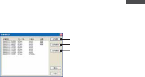
[ু൲ਓਬυΈນা ]δΗϋ
ু൲ਓਬυΈ͈ਓਬশۼ͞Ȃਓਬࠫض̦ນা̯̳ͦ͘ȃ
ಕփȇ
ু൲ਓਬυΈ͉डఱ 1000 ࡢ́͘༗ం̧̳́͘ȃ1000 ࡢ಼̢̹ͬાࣣু൲എͅυΈ
̦કݲ̯̳ͦ͘ȃυΈͬ༗ం̳ͥຈါ̦̜ͥાࣣ͉ȮυΈͬ༗ంȯδΗΰυΈέ
ͼσͬ༗ం̱̩̺̯̞̀ȃ
υΈْ࿂
[υΈͬٳ̩ ]δΗϋ
[υΈͬ༗ం ]δΗϋ
[υΈͬકݲ ]δΗϋ
ু൲ਓਬυΈ
ਓਬশ࣫ ---------------ু൲ਓਬ̦শ࣫ͬນা̱̳͘ȃ
ΈσȜίྴ ------------ু൲ਓਬ̦ਞၭ̱̹ΈσȜίྴͬນা̱̳͘ȃ
65
ঊܥྴ ------------------ু൲ਓਬ̦ਞၭ̱̹ঊܥྴͬນা̱̳͘ȃ
ࠫض ---------------------଼͈ાࣣ͉ߗฒȂ෴͈ાࣣ͉ ȩ ෴ ȩ ͂ນা̱̳͘ȃ
[υΈͬٳ̩ ]δΗϋ
༗ం̱̜̀ͥυΈέͼσȪڐಫঊ .glfȫͬٳ̧̳͘ȃ
[υΈͬ༗ం ]δΗϋ
ນা̯̞ͦ̀ͥυΈͬහփ͈ાਫ਼ͅ༗ం̧̳́͘ȃ
[υΈͬકݲ ]δΗϋ
ນা̯̞ͦ̀ͥυΈͬકݲ̱̳͘ȃ
66

67
4.Graph Operation
68
Graph
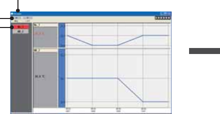
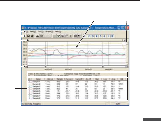
Temperature / Humidity Graph
Display Names and Functions
Ӹ
Ӳ
Ӷ
ӵ
ӳ
Ӵ
ӷ
ӱ
ӱGraph Area
The area in which the Graph is displayed. The horizontal axis shows time
and the vertical axis shows temperature / humidity data.
ӲA / B Cursor Movement Buttons and A / B Cursor Buttons
By clicking one of the arrow buttons at either side of the bar, you can
simultaneously move the A/B cursors. Click and drag the A or B button to
move the cursor to the left or right.
ӳA and B Cursor Position Information
The approximate date and time for the A and B cursor positions and the
time difference between the A cursor and the B cursor is displayed.
ӴChannel Info List Display
Displays data information for Channels 1 to 8. The list contains the
following info: Channel Name, Recording Interval, Amount of Data, Data

69
Values for AB Cursor positions, the High, Low and Average values for the
set calculation range.
ӵMenu Bar
Click on the desired menu in the Menu Bar to set or display each function
from which you can choose from an array of commands.
ӶToolbar
Buttons appear for frequently used commands.
ӱOpen File
ӲOverwrite Data
ӳSave Data asȤ
ӴChange Data Display Colors
ӵData Display ON/OFF
ӶReturn to Original Size
ӷStep-by-Step to Original
ӸSet High, Low, Avg. Calculation Range
ӹEdit Recording Conditions
ӺRe-order Channels
ӻErase Selected Channels Data
ӼVertical Axis Settings
ӽPrint
ӾHelp
ӿHide / View Channels
Ӳӵӷ Ӽ
ӱӳ ӶӴӻӸӹӺ ӽ ӿ
Ӿ
ӷHorizontal Gauge Bar and Button for Moving Horizontal Axis
By dragging the gauge you can move left and right to the data you want
to be displayed. The time axis moves by clicking these arrow buttons.
Ӹ
Vertical Gauge Bar and Button for Moving Vertical Axis
By dragging the gauge you can move up and down to the data you want
to be displayed. The vertical axis moves up or down by clicking these
arrow buttons.
70
Graph
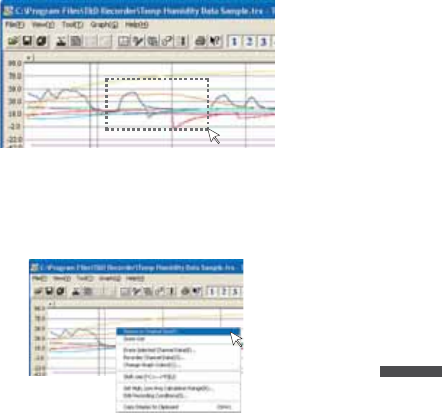
Zooming In and Out on the Graph
Zoom in Using the Mouse
With the left button drag the mouse to outline the area you want to zoom in on.
Menu Display Using the Mouse
By right clicking on the graph, the Menu will be displayed.With [Return to Original Size]
or [Step-by Step Return to Original] you can return both the vertical and horizontal axis
back to show the entire graph.
-These operations can be carried out via commands in the [Graph] Menu or by clicking
icons in the Toolbar.
About the Horizontal Axis
The entire graph shows in the horizontal axis the nearest data to the recording start
time and the latest data nearest the recording fi nish time for each channel 1~8. This
represents the full scale of the horizontal axis.
About the Vertical Axis
The entire graph shows in the vertical axis the lowest possible measurement value and
the highest possible measurement value for channels 1~8. This represents the full scale
of the vertical axis.
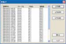
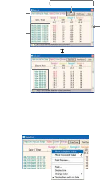
Data List Display
71
[Date / Time] Button
By clicking this button, you can shift the display between the recorded date and amount
of elapsed time since recording started.
Elapsed Time
Display
ӱ
Ӳ
Recorded
Date Display
[Date / Time] Button
ӱThis is a list of the data that was displayed in graph form. The highest
value is in RED, lowest is in BLUE, and the average is in PINK.
ӲScroll Bar: By dragging it up and down you can move to the data you
want.
Menu Display Using the Mouse
By right clicking on the list, the Menu will be displayed.
72
Graph
Editing the Graph
Changing Graph Display Colors
You can change the letters used in the data list display for each channel between
monochrome and channel color
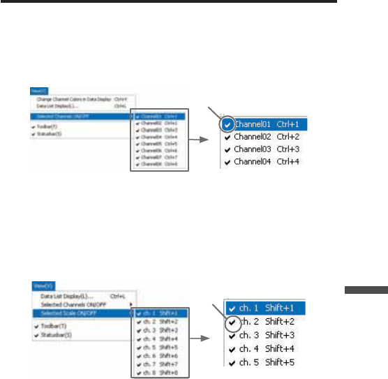
Selected Channels ON/OFF
1.
The channel numbers are displayed in the pull down menu of [Selected
Channels ON/OFF].
2.
Check the channel numbers you wish to display.
NOTE:
By clicking a Channel Number in the Toolbar, you can carry out the same operation.
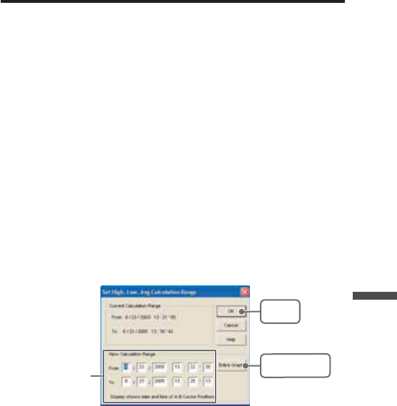
Set High, Low, Average Calculation Range
1.
Set the calculation range in the [Set High, Low, Avg. Calculation Range] box.
2.
By clicking the [OK] button, the high, low, average calculation range of each
channel data will be changed. On the graph display, the calculation range that
you have set will be displayed.
[OK]
button
[Entire Graph]
button
Enter the
numerical values
[Entire Graph] Button
To make the Calculation Range that of the Entire Graph, click the "Entire Graph" button.
The dates and times in the [Set High, Low, Avg. Calculation Range] box will be
displayed as those of the entire graph.
73
Set by using the AB Cursors
In the Graph Display, open the [Set High, Low, Average Calculation Range] box
adjusting the AB cursors to the desired start and end positions. The dates and times of
those cursors will be displayed automatically.
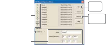
Edit Recording Conditions
1.
By clicking the [Ch.] button you wish to change, the information for that number
will be displayed in the "Edit Items".
2.
By clicking the [OK] button after changing, the setting will be completed.
[Restore]
button
[OK]
button
The selected
channel number
Channel Number
Enter letters and
numerical values
Name: Up to 32 letters can be entered.
Starting Date/Time:
The month, day, year, hour, minute and second can be changed.
NOTE:
- If you wish to continue to change other channels, repeat the process as in 1.
- The [Restore] button is effective only during the setting, and cannot return to the
condition it was after the [OK] button has been clicked.
74
Graph
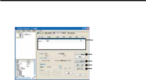
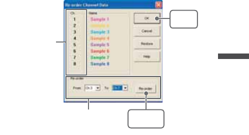
Re-order Channel Data: From the [Tools] Menu
There are two ways for re-ordering.
-Move by dragging the channel number
-Move by selecting the channel number
ȺMove by dragging the channel numberȻ
Click on the channel of data you wish to move and drag and drop it to the desired new
channel position.
ȺMove by selecting the channel numberȻ
1.
Enter in From: Ȓ, the channel number you wish to move from, and enter the
channel number to which you want to move in To: Ȓ .
2.
By clicking the [Re-order] button, the movement will be completed.
NOTE:
The [Restore] button is effective only during the setting, and cannot return to the
condition it was by clicking the [OK] button.
[Re-order]
button
Drag and drop the
channel number to the
desired new position
[OK]
button
If you wish to move Ch 3. to Ch 7.
simply set From ɨCh 3.
To ɨCh 7.
75
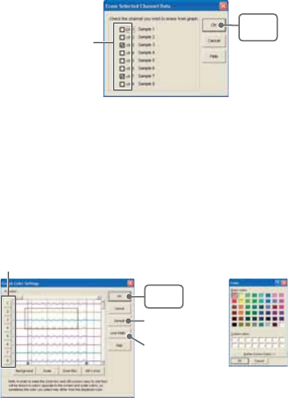
Erase Selected Channel Data
1.
Put a check on the channel number you wish to erase.
2.
By clicking on the [OK] button, the deletion will be completed.
[OK]
button
Put a check on the
check box
Shift Unit (Ɏ/ ȌF)
By clicking on [Shift Unit(Ɏ/ ȌF)], you can automatically change the temperature unit
scale in the graph display and in the channel info list.
Change Graph Colors
1.
Click the channel number of which you wish to change the color.
2.
By clicking each button, color samples will be displayed. Choose the color you
want and click the [OK] button.
3.
After confi rming the color, by clicking the [OK] button the change will be
completed.
[Channel No.] button
[Default]
button
[OK]
button
[Line Width...]
button
ȴColor Sampleȵ
76
Graph
NOTE:
By clicking the [Return to Default] button, you will return to the color settings when the
software was opened.
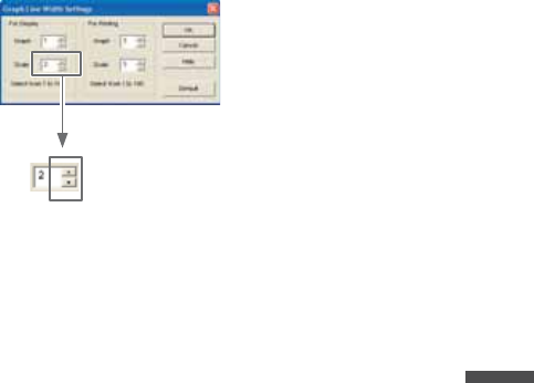
[Graph Line Width Settings] Button
Change the width of the data lines and the scale lines.
Every time you click on
ɣ, the numerical value gets larger,
ɥ, the numerical value gets smaller.
77
Copy Display to Clipboard:From the [Tools] Menu
By clicking [Copy Display to Clipboard], you can copy the currently displayed window to
the clipboard and make use of the graph pasting in other software.
Graphȇ From the [Graph] Menu
Return to Original Size
Return from zooming in on one part of data
Zoom In / Zoom Out
Zooms in or out one step at a time
Move Cursor Right / Left
Simultaneously move the AB Cursors to the right or left.
Move Graph Right / Left
Move the graph display to the right or left.
Move Graph Up / Down
Move the graph display up or down.
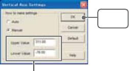
Vertical Axis Settings (AUTO in Default Settings)
Set the vertical axis scale (temperature)
AUTO: The vertical axis will automatically be changed according to the
values of the data.
MANUAL:You can set the upper and lower values of the vertical axis scale.
Enter the range of the
vertical axis scale.
[OK]
button
78
Graph
Multi-scale Graph
Display Names and Functions
ӱ Ӻ
ӹ
ӵ
Ӳ
ӳ
Ӵ
Ӹ
ӷ
Ӷ
t
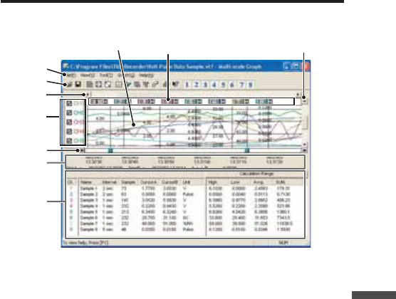
ӱGraph Area
The area in which the Graph is displayed. The horizontal axis shows time
and the vertical axis shows the unit of data after having used the
conversion equation to convert the original measured voltage.
ӲA / B Cursor Movement Buttons and A / B Cursor Buttons
By clicking one of the arrow buttons at either side of the bar, you can
simultaneously move the A/B cursors. Click and drag the A or B button to
move the cursor to the left or right.
ӳA and B Cursor Position Information
The approximate date and time for the A and B cursor positions and the
time difference between the A cursor and the B cursor is displayed.
ӴChannel Info List Display
79
Displays data information for Channels 1 to 8. The list contains the
following info: Channel Name, Recording Interval, Amount of Data, Data
Values for AB Cursor positions, the High, Low and Average values for the
set calculation range.
ӵThe Vertical Axis Display ON/OFF
Shift the vertical axis scale display ON/OFF.
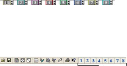
ӶVertical Axis of Each Channel
The vertical axis scale is displayed for each channel. By clicking [ ɣɥ ],
the axis can be scrolled for each channel.
ӷMenu Bar
Click on the desired menu in the Menu Bar to set or display each function
from which you can choose from an array of commands.
ӸToolbar
Buttons appear for frequently used commands.
ӱOpen File
ӲOverwrite Data
ӳData List Display
ӴReturn to Original Size
ӵStep by Step to Original
ӶSet High, Low, Avg. Calculation Range
ӷEdit Recording Conditions
ӸRe-order Channels
ӹMerge Channel Data
ӺErase Selected Channel Data
ӻPrint Preview
ӼHelp
ӽHide / View Channels
Ӳӵӷ Ӽӱӳ ӶӴӻӸӹ Ӻ ӽ
ӹHorizontal Gauge Bar and Button for Moving Horizontal Axis
By dragging the gauge you can move left and right to the data you want
to be displayed. The time axis moves by clicking these arrow buttons.
ӺVertical Gauge Bar and Button for Moving Vertical Axis
By dragging the gauge you can move up and down to the data you want
to be displayed. The vertical axis moves up or down by clicking these
arrow buttons.
80
Graph
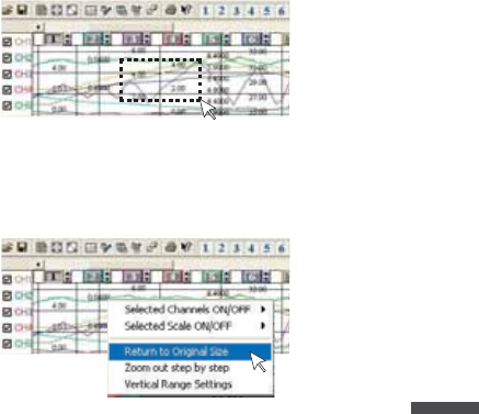
Zooming In and Out on the Graph
Zoom in Using the Mouse
With the left button drag the mouse to outline the area you want to zoom in on.
Menu Display Using the Mouse
By right clicking on the graph, the Menu will be displayed.With [Return to Original Size]
or [Step-by Step Return to Original] you can return both the vertical and horizontal axis
back to show the entire graph.
81
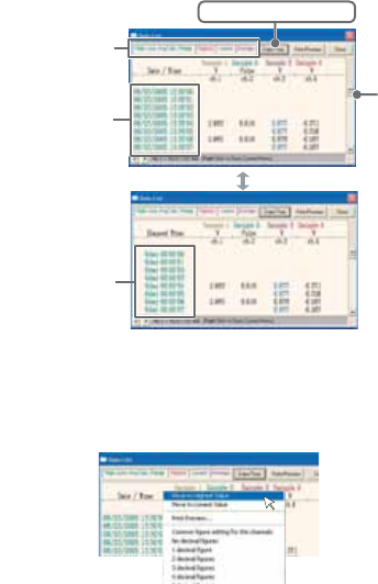
Data List Display
[Date / Time] Button
By clicking this button, you can shift the display between the recorded date and amount
of elapsed time since recording started.
Elapsed
Time Display
ӱ
Ӳ
Recorded
Date Display
[Date / Time] Button
ӱThis is a list of the data that was displayed in graph form.
The highest value is in RED, lowest is in BLUE, and the average is in ȁPINK.
ӲScroll Bar: By dragging it up and down you can move to the data you want.
Menu Display Using the Mouse
By right clicking on the list, the Menu will be displayed.
82
Graph
Editing the Graph
Selected Channels ON/OFF
1.
The channel numbers are displayed in the pull down menu of [Selected
Channels ON/OFF].
2.
Check the channel numbers you wish to display.
Check
*
By clicking a Channel Number in the Toolbar, you can carry out the same operation.
Scale Display ON/OFF
1.
The channel numbers are displayed in the pull down menu of [Selected Scale
ON/OFF].
2.
Put a check next to the channel number(s) you wish to be displayed.
Check
*You can also hide or view channel scales by checking or mchecking the channel
number fo the left of the graph.
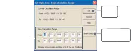
83
Set High, Low, Average Calculation Range
1.
Set the calculation range in the [Set High, Low, Avg. Calculation Range] box.
2.
By clicking the [OK] button, the high, low, average calculation range of each
channel data will be changed. On the graph display, the calculation range that
you have set will be displayed.
[OK]
button
[Entire Graph]
button
Enter the
numerical value.
[Entire Graph] Button
To make the Calculation Range that of the Entire Graph, click the "Entire Graph" button.
The dates and times in the [Set High, Low, Avg. Calculation Range] box will be
displayed as those of the entire graph.
Set by using the AB Cursors
In the Graph Display, open the [Set High, Low, Average Calculation Range] box
adjusting the AB cursors to the desired start and end positions. The dates and times of
those cursors will be displayed automatically.
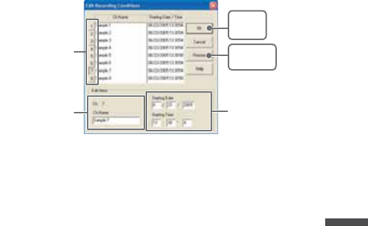
84
Graph
Edit Recording Conditions
1.
By clicking the [Ch.] button you wish to change, the information for that number
will be displayed in the "Edit Items".
2.
By clicking the [OK] button after changing, the setting will be completed.
Channel Number [Restore]
button
[OK]
button
Enter letters and
numerical values
The selected
channel number
Name: Up to 32 letters can be entered.
Starting Date/Time:
The month, day, year, hour, minute and second can be changed.
NOTE:
- If you wish to continue to change other channels, repeat the process as in 1.
- The [Restore] button is effective only during the setting, and cannot return to the
condition it was after the [OK] button has been clicked.
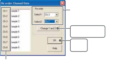
85
Re-order Channel Data: From the [Tools] Menu
There are two ways for re-ordering.
- Move by dragging the channel number
- Move by selecting the channel number
ȺMove by dragging the channel numberȻ
Click on the channel of data you wish to move and drag and drop it to the
desired new channel position.
ȺMove by selecting the channel numberȻ
1.
Enter in From: Ȓ, the Channel number you wish to move from, and enter the
Channel number to which you want to move in To: Ȓ .
2.
By clicking the [Re-order] button, the movement will be completed.
Drag and drop the channel number
to the desired new position.
[Change 1 and 2]
button
[OK]
button
If you wish to move Ch3 to Ch7.
simply set From ɨCh3,
To ɨ!Ch7.
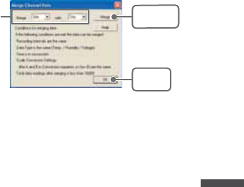
86
Graph
Merge Channel Data
You can merge two different sets of data into one set of data.
1.
Click theȬɥȭbutton, and select the channels you wish to merge.
The following kinds of data cannot be merged:
- Recording intervals are different
- Measurement times overlap (Merging is possible after adjusting the times in
[Editing Recording Conditions])
- Data types are different (Merging is possible between same types of data; like
temperature/humidity)
[OK]
button
[Merge]
button
Ex: If you wish to merge
Ch.3 with Ch.7
2.
By clicking the [Merge] button, the merging will be completed.
3.
Click the [Close] button to fi nish the merging.
NOTE:
The channel number and other conditions of the merged data will become those
conditions set in the channel that you selected in the second box.
Erase Selected Channel Data
1.
Put a check on the channel number you wish to erase.
2.
By clicking on the [OK] button, the deletion will be completed.
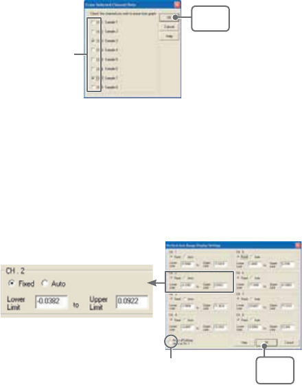
87
[OK]
button
Check
Vertical Axis Range Display Settings
You can set the upper and the lower limits of the graph's vertical axis scale for each
channel.
1.
Check [Fixed] of the channel you wish to set.
2.
Enter upper and lower limit values.
Set the lower limit at more than –40,000 and set the upper limit at less than
40,000.
3.
By clicking the [OK] button, the setting will be completed.
Select [Fixed] and enter numerical
values.
Check here, If you wish to make
all of the settings the same.
[OK]
button
[Make all channel settings the same as Ch.1]
Set CH.1 [Fixed] and by putting a check on [Make all Settings the same as Ch.1]; all
channel settings will be the same as CH.1 regardless of other channel settings.
NOTE:
If you have put a check on [Fixed], the lines in the graph may exceed the boundaries of
the graph.

88
Graph
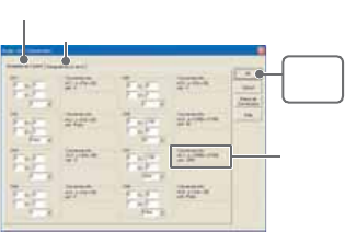
89
Scale and Unit Conversion
You can convert the scale and the unit of downloaded data for each channel.
1.
Select from [Designate by 2 points] tab or [Designate by y=ax+b] tab.
[OK]
button
[Designate by 2 points] tab
Conversion Info
[Designate by y=ax+b] tab
2.
Set conversion formulas and units.
3.
By clicking the [OK] button, the setting will be completed.
[Conversion Info]
Current conversion formulas and units are displayed here.
"y" indicates the data after conversion, and "x" indicates the voltage
entering from the sensor.
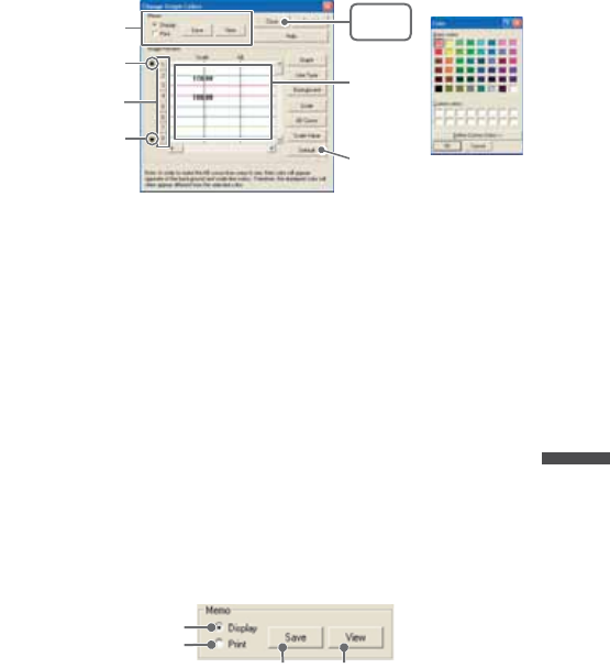
90
Graph
Change Graph Colors
ȴColor Sampleȵ
Memo
[Close]
button
[Default]
button
Image
Preview
[Channel Number]
button
ɣ
ɥ
1.
Click the [Channel Number] button, and click the button of the item that you wish
to change.
- When changing colors, click on a button to display the color
samples. Choose the desired color and click the [OK] button to
change the color.
- If you wish to change line width, every time you click the Ȭɣȭ
button, the width gets wider, and every time you click the Ȭɥȭ
button, the width becomes more narrow.
2.
Confi rm the width in the image preview and click the [Close] button to complete
the change.
- By clicking the [Return to Default] button, the color settings will
return to the Default Settings.
[Memo]
You can save the settings for Display and/or Print respectively.
1.
Select "Display" or "Print".
2.
By clicking the [Save] button, the settings will be saved.
ȆBy clicking the [View] button, you can see the settings that had
been previously saved.
[Save] button [View] button
For Display
For Print
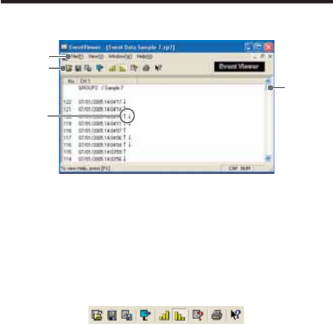
91
Event Viewer
Display Names and Functions
ӳ
Ӳ
Ӵ
ӵ
ӱ
ӱData Window
In the data window are displayed the Data Number, Channel Name,
Recorded Date and Time, Rising Edge/Falling Edge.
ӲMenu Bar
Click on the desired menu in the Menu Bar to set or display each function
from which you can choose from an array of commands.
ӳToolbar
Buttons appear for frequently used commands.
ӱOpen File
ӲSave Data asȤ
ӳSave as Text File
ӴShift Display
ӵDisplay in ascending order
ӶDisplay in descending order
ӷFile Info
ӸPrint Preview and Print
ӹHelp
ӹӸӷӶӵӴӳӲӱ
Ӵ ɪ/ɫ/ ɪɫ
Ȭɪȭ denotes rising pulse
Ȭɫ ȭ denotes falling pulse
Ȭ
ɪɫ
ȭ denotes a simultaneously occurring rising and falling pulse.
ӵScroll Bar
You can move up and down to the desired position in the graph.
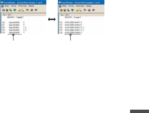
92
Graph
Shift Display
You can shift the display between the recorded date and the amount of elapsed time
from the last recorded data.
Recorded Date Display
Elapsed Time Display
Shift Ascending / Descending
You can shift the display to view the recorded data either from the oldest to the newest
or from the newest to the oldest.
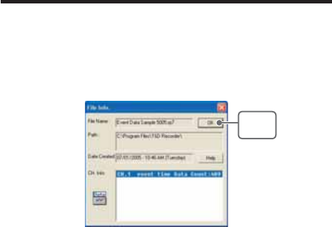
93
Event Viewer:File Info
View File Info about data in the currently displayed data list.
1.
Select [File Info] from the [View] Menu.
2.
Click the [OK] button to return to the previous window.
File Nameȇ File name of data currently in display
Pathȇ Location where file is saved
Date Createdȇ The date and time when the data file was created
CH. Infoȇ Channel Number, Recording Method and Data Count
[OK]
button
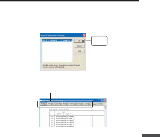
94
Graph
Event Viewer:Print Preview and Print
1.
In the [File] Menu, select [Print Preview and Print].
2.
In [Select Channel for Printing] the channel numbers and names will appear.
Select the number of the channel(s) you wish to print and click [OK].
-It is possible to choose up to 4 channels at one time.
[OK]
button
3.
The [Print Preview] will appear. After confi rming it is what you wish to print, click
[Print] to start printing.
Button Functions
[Print] Print box will appear and printing will begin
[Previous] Preview the previous page
[Specify P] Specify the page you wish to preview in the [Specify Page to be
Viewed] box and a preview of that page will appear
[Next] Preview the next page
[Reduce] Reduce the size of the displayed page
[Enlarge] Enlarge the size of the displayed page
[Close] Close the Print Preview Window and return to the Main Window
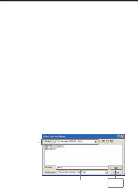
95
Saving a File
If you have clicked [Display the graph after downloading recorded data], and you make any
changes to the data after displaying, make sure to save those changes if necessary.
NOTE:
See p.62 for details about compatible data fi le types.
3 Ways to Save Files
In the [File] Menu, select [Overwrite All Data]
Will save any changes to fi le without changing File Name and Saving
Location. The same operation can be carried out from [Save] in the
Toolbar.
In the [File] Menu, select [Save All Data as...]
Save with a new File Name.
In the [File] Menu, select [Save Displayed Data]
Save only that data in the current display. This is handy when you wish to
save only the desired data.
EX: [Save All Data as...]
1.
Select [Save All Data as...] in the [File] Menu.
2.
Specify the [Location] and enter a [File Name].
3.
Click [Save] to complete the saving process.
Specify Location
Enter a File Name [Save]
button
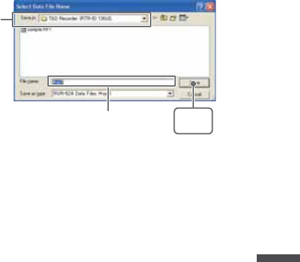
96
Graph
Saving Event Viewer Data
In the [File] Menu, select [Save All Data as...]
Save with a new File Name.
Specify Location
Enter a File Name [Save]
button
1.
Select [Save All Data as...] in the [File] Menu.
2.
Specify the [Location] and enter a [File Name]
3.
Click [Save] to complete the saving process.
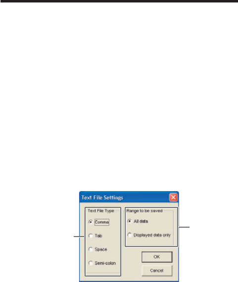
97
Saving Data in Text File
By saving the recorded data as text fi le, you can create a fi le type that can be read by
common spreadsheet software.
When saving Temp/Humid Graph and Multi-scale Graph data as
Text File
1.
Select [Save in Text File] in the [File] Menu.
2.
Select the [Text File Type] and [Range to be Saved], and click [OK].
- Comma, Tab, Space, and Semi-colon are codes used by common spreadsheet
software, such as Excel and Lotus, when reading Text File to divide cells.
3.
Designate the location to which the fi le should be saved and click [Save] to
create and save the data as a Text File document.
- The extension for the created fi le will be [.TXT].
NOTE:
- Text File cannot be read into T&D for Windows graphs.
- The display layout differs between the Temp/Humid Graph or the Multi-scale Graph.
EXȇTemp/HumidGraph Text File Settings Windowȁ
Select the Text File
Type
Select the Range
to be Saved
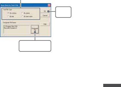
98
Graph
When saving Event Viewer data as Text File
1.
Select [Save Data in Text File] in the [File] Menu.
2.
Select the [Text File Type] and click [Designate File] and [OK].
- Comma, Tab, Space, and Semi-colon are codes used by common spreadsheet
software, such as Excel and Lotus, when reading Text File to divide cells.
[OK]
button
[Designate File]
button
Select the Text File Type
3.
Designate the location to which the fi le should be saved by clicking [Designate
File] and click [OK] to create and save the data as a Text File document.
NOTE:
- The extension for the created fi le will be [.TXT].
- Text File cannot be read into T&D for Windows graphs.
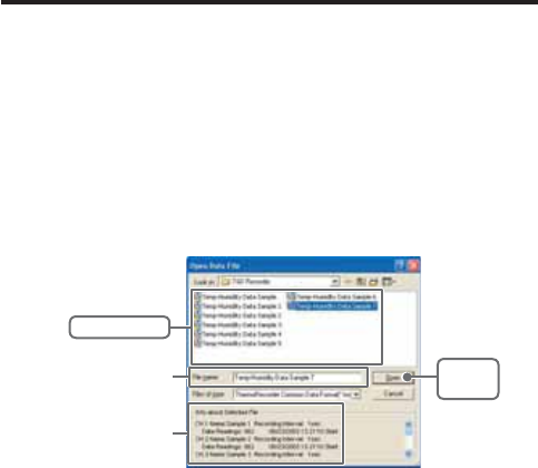
99
Opening a File
To open a previously saved fi le, designate the fi le name to open it. To open multiple fi les at
once, hold down the Ctl-key and select the fi les you with to open.
NOTE:
See p.62 for details about compatible data fi le types.
Opening a File with the Temp/Humid Graph and Multi-scale
Graph
1.
Select [Open] in the [File] Menu
2.
Select the name of the data you wish to open and click [Open] to view the data
in graph form.
[Open]
button
Selected File Info
Selected File Name
Select a File
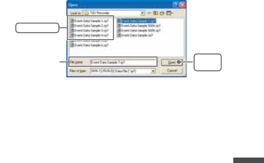
100
Graph
Opening a File with the Event Viewer
1.
Open the Event Viewer from the RTR-57C/57U or RVR-52A [Graph] Menu.
2.
In the Event Viewer Window under the [File] Menu, click [Open] and a list will
apper.
[Open]
button
Select a File
Selected File Name
101

102
Others
Others

103
Troubleshooting
˭: The computer won't communicate via the Serial Port. What should
I do?
˝: Try two or three times to fi nd the port connection by using the Auto-
detect function.
˝: Check to make sure that the power of the main unit is ON.
˝: Check to make sure that the connection is proper. Communication will
take place only through the serial port (RS-232C) and will not work
through the printer port or any other port.
˝: Check to make sure that you can control the Thermo Recorder via the
software.
˝: If you have access to another computer, try seeing if communication
works with the other computer.
˝: If you have a computer with energy saving function settings, make sure
that the serial port has not been turned off. Especially on NEC brand
PC98 notebook computers the default setting maybe such.
˝: Check to make sure that the serial port has not been rendered
unusable by the BIOS setting.
˝: Make sure that the serial port setting has not been made to render the
port unusable. With some computers, especially all-in-one computers
the serial port serves as the modem jack.
How to check
1.
View in the Device Manager Window.
For Windows XP or 2000
1.On the Desktop, right click on [My Computer] and click on [Properties].
2.In the System Properties Window, click on the [Hardware] Tab, then
click on the [Device Manager] button to view the Device Manager
Window.
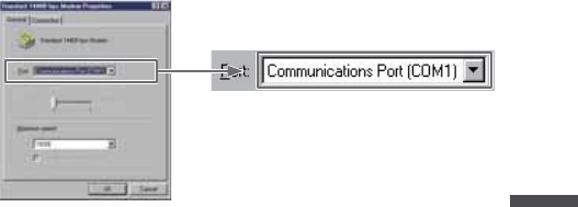
104
Others
For Windows 98SE or ME
1.Open the [Control Panel] and double click on [System] to display the
[System Properties].
2.Click the [Device Manager] Tab to view the Device Manager Window.
2.
In the [Device Manager], click on [Port (COM&LPT)] and check to see if under
that appears [Com Port (COM1)] or [Com Port (COM2)].
If a port appears, it should be usable.
- If a mark [ Ȋ] or [ ȿ] appears next to the port, this communication port is
unusable. If you cannot use a communication port please contact your computer
company.
- To fi nd out more details about an unusable communication port:
Select the port with a [ Ȋ] mark, and then click on [Properties] to view the details
about that port.
˝: If your computer has an internal modem, make sure that the
communication port is not being used by it. When the communication
port is being used as the modem port, that port cannot be used. Either
quit using the modem or use another port.
ɦAn example of the modem using a communication
port (COM 1).
˝: If your computer has no serial port, use a Serial-USB conversion cable
and carry out communication via USB connection. We recommend [I.O
DATA USB-RSAQ3] , [ELECOM UC-SGT] and [IOGEAR UC-232A]
Serial-USB conversion cables. If you are using an NEC Lavie J
Notebook Computer(NEC LJ-500), please use [I.O DATA USB-RSAQ3].
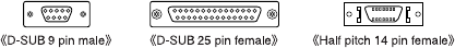
105
˝: Sometimes communication will not work if a switch has been added to
the serial port (RS-232C) or an extension cable has been added to the
communication cable.
˝: Check to see if some other communication software is in use.
˝: If your desktop computer has two serial ports, try connecting the
communication cable to the other port and try communicating again.
˭: I can't get the communication cable connected to the computer.
What should I do?
˝: Please connect the communication cable provided with the Thermo
Recorder into the serial port of your computer (D-SUB 9 pin male
connector). If for some reason you cannot connect directly, please use
an appropriate adapter (gender changer plug) as explained below.
Ȇ
If the connector on your computer is a D-SUB 9 pin male then there is no need for an
adapter.
Ȇ
If the connector on your computer is a D-SUB 25 pin female then use an adapter (D-SUB 25
pin male to a D-SUB 9 pin male).
Ȇ
If the connector on your computer is a Half pitch 14 pin female then use the adapter (Half
pitch 14 pin male to a D-SUB 9 pin male) or a combination (Half pitch 14 pin male to D-SUB
25 pin male) and (D-SUB 25 pin female to a D-SUB 9 pin male).
˭: The date and the time of the recorded data are different from the
actual date and time. Why?
˝: The Thermo Recorder has no internal clock. When you set up a
programmed recording start or when you download data, the date and
time that are shown are taken form your computer's clock. If your
computer's clock is not correct, it will affect the recorded data.

106
Others
Specification
RTR-50 for Windows
చ؊ܥਅ RTR-50ȆRTR-51ȆRTR-52ȆRTR-53ȆRVR-52
ܥෝ :RTR-5 ܱΑΗȜΠȪ௲শȟထȫȆܱ೪গȆུఘ୭උ͙ࣺ͙Ȫܱ
ۼڞȆܱκȜΡȆഩ౻ॼၾȆഩ෨ޑഽȆ࡛हΟȜΗ৾ංȆ
ྫܱͥ͢ͅٳই༗ࢌ ୭خෝȫȆܱΟȜΗ͈ݟ̞ષ̬
ܥෝ :RVR-5 ܱΑΗȜΠȪ௲শȟထȫȆܱ೪গ
ུఘ୭උ͙ࣺ͙ȪܱۼڞȆܱκȜΡȆഩ౻ॼၾȆഩ෨ޑഽȆ
࡛हΟȜΗ৾ංȆഩգ௶͈ਅ႒ <শ / >)
ΩσΑ௶͈ਅ႒ (ၛ̻ષ̦ͤ <Lo ɨHi>/ ၛ̻ئ̦ͤ <Hi ɨLo>/
ྫܱͥ͢ͅٳই༗ࢌ ୭خෝȫȆܱΟȜΗ͈ݟ̞ષ̬
ܥෝ :
RTR-50
ঊܥ ,ΈσȜί൝͈୭ȆඤယນাȆਔ෨ତ๔୭
ΟȜΗ༭৾ංȆΟȜΗૂ༭ນাȆΟȜΗॉੰȆΟȜΗݟ̞ષ̬
Ȇષئࡠ͈୭ȆκΣΗςϋΈ /࠙༭۬ণ୭ȆΈρέκΣΗς
ϋΈȆ࠙༭ιȜσȆু൲ਓਬ
̷͈ఈ͈ܥෝ ΏςͺσεȜΠু൲
Temp/Humidity Graph
Graph Temp/Humidity Graphs for Each Channnel (Zoom out / in and scroll)
/ Change Channel Colors / Turn ON and OFF Channnel Display
Data Display ΙλϋΥσྴȆܱۼڞȆΟȜΗତȆडࣞȆडȆȆ
ౙպ
හփ̈́ 2തȪAB ȜΕσպ౾ȫ͈أഽ /শ
හփ̈́ 2തȪAB ȜΕσպ౾ȫۼ͈أഽओ͈ॳ
ΙλϋΥσତ 8ΙλϋΥσȁ൳শນাȟੜၑ
(RTR-53 ͉4రȂRTR-51/52 ͉8రȁȁईहੜၑخෝ )
Others ΟȜΗ֚။ນাȆࠗॳํսȪܢۼȫ୭ȆΟȜΗιϋΞϋΑ
ΙλϋΥσྀ͈ΟȜΗॉੰȆΙλϋΥσྀ͈ΟȜΗ͍ఢ̢

107
Multi-scale Graph
Graph ΙλϋΥσ௶͈୬ͦΈρέນাȪζ;ᾼͥ͢Έρέ͈ڐ
ఱ/ੀ /Α·υȜσນাخෝȫ
ΙλϋΥσྀ͈ນাρȜ་ࢵȆΙλϋΥσྀ͈ນাȟນা୨
ͤఢ̢
Data Display ΙλϋΥσྴȆܱۼڞȆΟȜΗତȆडࣞȆडȆȆ
ୟॳȆౙպȆහփ̈́ 2തȪAB ȜΕσպ౾ȫ͈௶ /শȆ
හփ̈́ 2ത(AB ȜΕσպ౾ȫۼ͈শۼ͈ओ ss
ΙλϋΥσତ 8ΙλϋΥσȁ൳শນা /ੜၑ (RTR-53 ͉4రȂRTR-51/52Ȇ
RVR-52 ͉8రईहੜၑخෝ )
Others ΟȜΗ֚။ນাȆࠗॳํսȪܢۼȫ୭ȆΟȜΗιϋΞϋΑ
ΙλϋΥσྀ͈ΟȜΗॉੰȆΙλϋΥσྀ͈ΟȜΗ͍ఢ̢Ȇ
ਸέσΑΉȜσ୭
Event Viewer
Event List ΙλϋΥσྀ͈ͼαϋΠশ͈֚࣫။ນাȪζ;ΑȆ΅ȜδȜΡͅ
ͥ͢Α·υȜσນাخෝȫ
෨ࠁ͈ၛ̻ષ̦ͤ (Lo ɨHi)/ ၛ̻ئ̦ͤ (Hi ɨLo)
ΙλϋΥσତ 64 ΙλϋΥσȁ൳শນা /ੜၑ (RVR-52 ͈ͼαϋΠশܱ࣫ΟȜ
Η͈͙ )
̷͈ఈ͈ܥෝ ນা୨ͤఢ̢Ȇઌਜ਼ /ࣛਜ਼୨ͤఢ̢
̷͈ఈ
֣क़ Έρέ֣क़ȆΟȜΗ֚။֣क़
OS Microsoft Windows 98SE/Me ུࢊๅ
Microsoft Windows 2000/XP ུࢊๅ
PC/CPU Pentium 90MHz ոષ൏श͈ AT ࡽ۟ܥ̹͉͘ NEC 98 ΏςȜΒ
USB ȆRS-232C ȪRS-232C D-Sub 9 άϋȫ̦ঀဥخෝ
൲ै۪ޏ Microsoft Windows ̦ୃુͅ൲ै̳۪ͥޏ

108
Others
RTR-50
చ؊ܥਅ RTR-5,RVR-5
ܥෝ ྫȇ ΟȜΗݟષ̬ȂκΣΗນাȂܱٳইȂྫಎࠑܥෝ
ȇΟȜΗݟષ̬Ȃܱٳই
ഩ࡙ USB ΨΑΩχȜȂౙ२ۋഩ౻ȿ 2ȂAC ͺΘίΗ (AD-0601) [ Υ
·Η EIAJ ഩգߊ 2Ηͼί ]
ͼϋΗέͿȜΑ USB [MiniB Υ·Η ] / Ώςͺσ [ηΣΏςͺσ ](19200bps)
ྫ༷ අഩႁྫ (ARIB STD-T67) 426MHz ఝ 4 ΙλϋΥσ
ྫഩݻၗ 100m( ࡉ̱͈ၻ̞ೄ̞̀ͅ )
শۼ ྫȇΟȜΗ FULL ́ 420 ຟ(ಎࠑܕྚঀဥশ )ಎࠑܕͬঀ
ဥ̳ͥાࣣȂಎࠑܕˍరྀͅષܱ͈শۼ̦حॳ̧̯̞̳ͦ̀͘ȃ
ȇΟȜΗ FULL ́ 160 ຟ
ນাܥෝ ႂ LED( ྫȂPC শͅത )
ഩ౻ྵ ౙ२ۋഩ౻ x 2 ͈൲ै́ 15ۼ͈ಎࠑܕ̱͂̀ঀဥ̱̹
ાࣣȂ 6ώ
ུఘ༹ 95[mm] ȿ65[mm] ȿ24.5[mm]( ̯ࣞȿ໙ȿ࢚̯ )
ུఘৗၾ 60g( ഩ౻܄̴͘ )
൲ैഩգ 2.5V ȡ7.0V
કഩၠ ྫশ 50mA
ུఘ൲ै۪ޏ أഽ -10-60Ɏ(ٸ໐ഩ࡙ঀဥশ -30-60Ɏ)
ഽ 20-80%RH( ࠫႺ̱̞̭̈́͂ )
ັ௺ USB ΉȜήσȂΕέΠ;Ϳͺ CDȂ৾ե୰ྶ
ίΏοϋ ΏςͺσΉȜήσ (TR-07C)ȂAC ͺΘίΗ (AD-0601)Ȃٸ໐ഩ࡙ξ
ΣΛΠ (AD-0620)
109

110
For product information or questions contact us at:
http://www.tandd.co.jp/
5652-169 Sasaga Matsumoto, Nagano Japan 399-0033
Tel: +81-263-27-2131
Fax: +81-263-26-4281
E-mail: overseas@tandd.co.jp
Offi ce Hours : Monday to Friday 9:00-12:00 / 13:00-17:00
(GMT +9:00 Tokyo Time)
RTR-50 Wireless Communication Port
Published by T&D CORPORATION
© copyright 2006 T&D Corporation. All rights reserved.

Wireless Communication RTR-50 Warrant
Customer's name:
Address:
Phone No.:
Dealer's name:
Address:
Phone No.:
Guarantee period 12 months from date of purchase
Date of purchase
Statement of Limited Warranty
1. This product is warranted to be free from defects in materials and workmanship for a period of
one (1) year following the date of purchase. Should the product fail to operate per
specifi cation in normal use during this period T&D will repair the unit or provide a
replacement free of charge. T&D will not accept returns for any reason other than defects
during the warranty period, and will not accept any product that has been misused, dropped,
abused or inappropriately used or mistreated at any time.
2. This warranty is strictly limited to repair or replacement-in-kind for defective product. T&D
makes no other warranty, either express or implied, and will not accept liability beyond the
remedies stated herein. Specifi cally, T&D will not accept liability for direct, indirect, special,
consequential or incidental damages arising from the use of this product.
3. Customers wishing to submit a defective product for repair or replacement during the warranty
period should fi rst contact the dealer from whom it was originally purchased. After receiving
a return authorization the defective product should then be packaged along with a description
of the diffi culties being experienced, proof of purchase and all included accessories and
materials, and returned it to the dealer. In the event of diffi culty contacting the original
dealer, customers should contact the nearest authorized T&D sales representative. A list of
these can be found on the company's website, www.tandd.com, or it can be obtained by
contacting TandD US directly.
4. This limited warranty statement gives the customer specifi c legal rights. The customer may
also have other rights which vary from state to state in the United States, from province to
province in Canada, and from country to country elsewhere in the world. To the extent this
limited warranty statement is inconsistent with local law, this statement shall be deemed
modifi ed to be consistent with such local law.
5. For further information relating to product repair or replacement, or for other service questions
after the termination of the warranty period, customers should contact their local authorized
T&D sales representative.